EnOcean TCM515U Transceiver Module User Manual
EnOcean GmbH Transceiver Module
UserManual.wiki
>
EnOcean
>
TCM515U User Manual
>
User Manual
Contents
1.
Antenna Chip User Manual
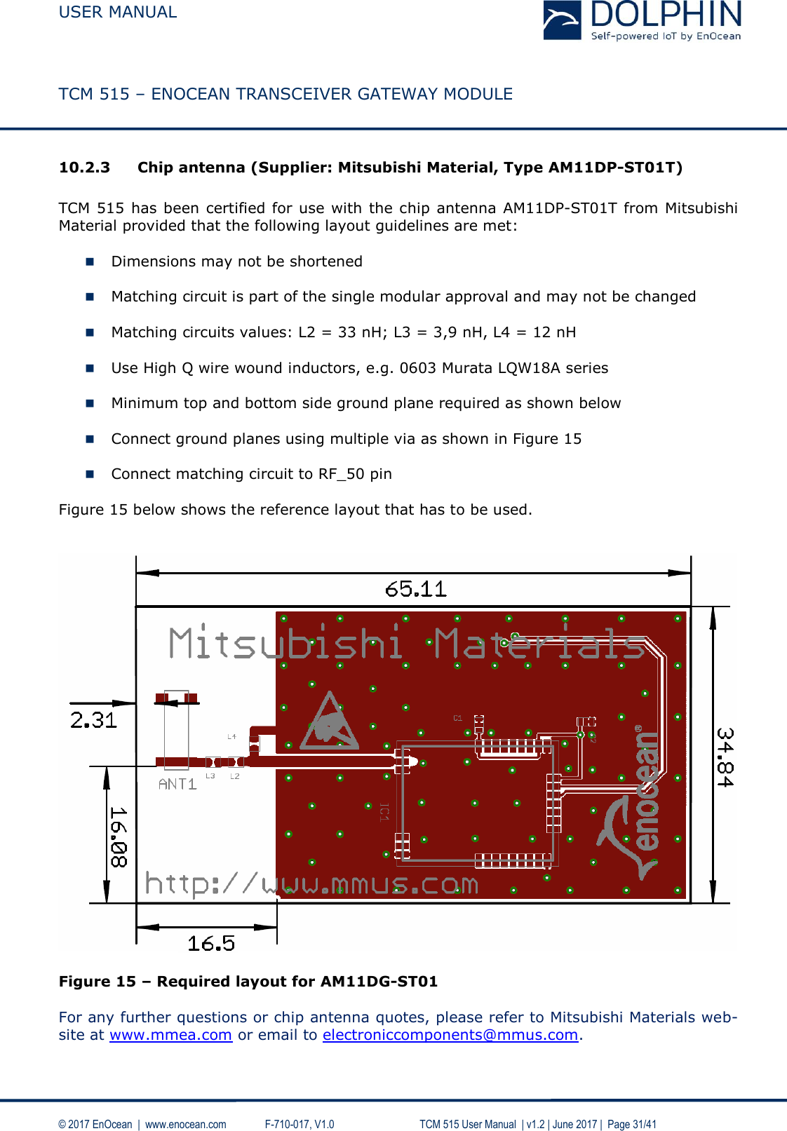
2.
Antenna Chip Layout User Manual
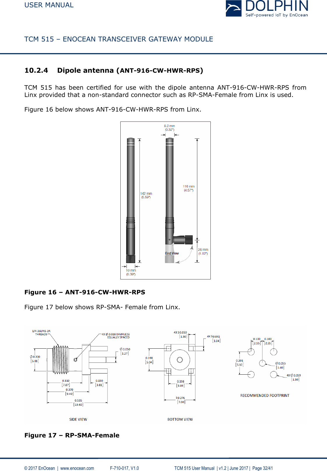
3.
Antenna Dipole User Manual
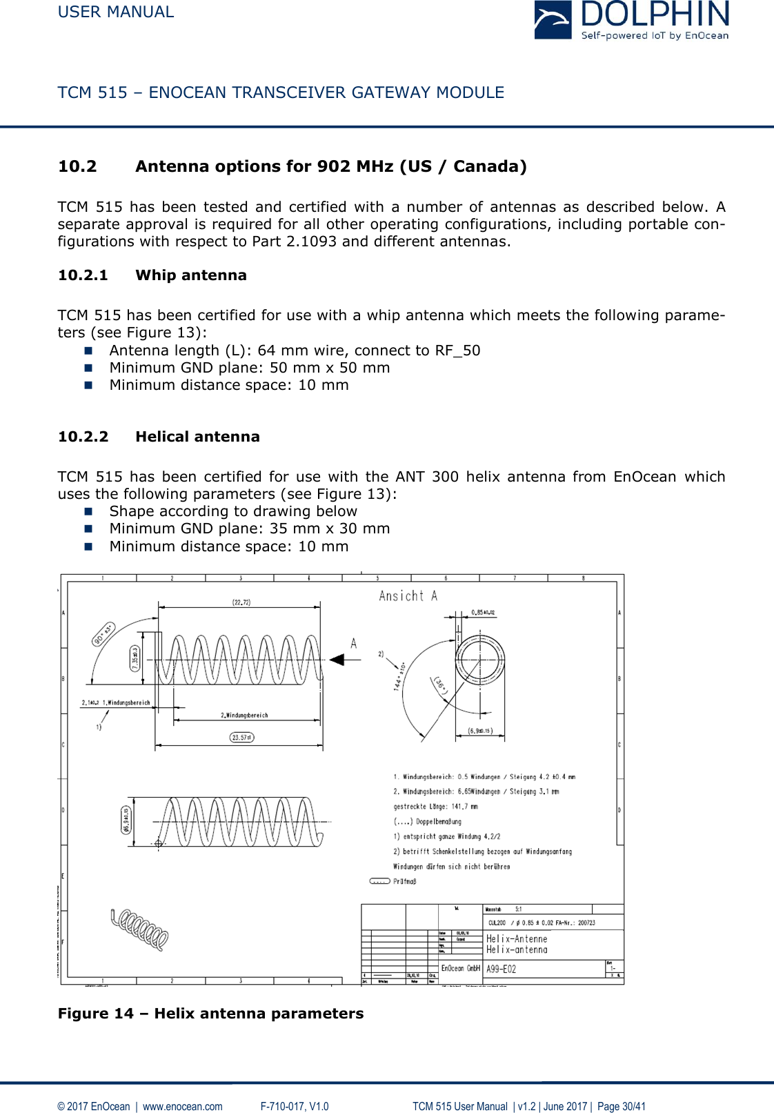
4.
Antenna Helix User Manual
5.
Antenna PCB User Manual
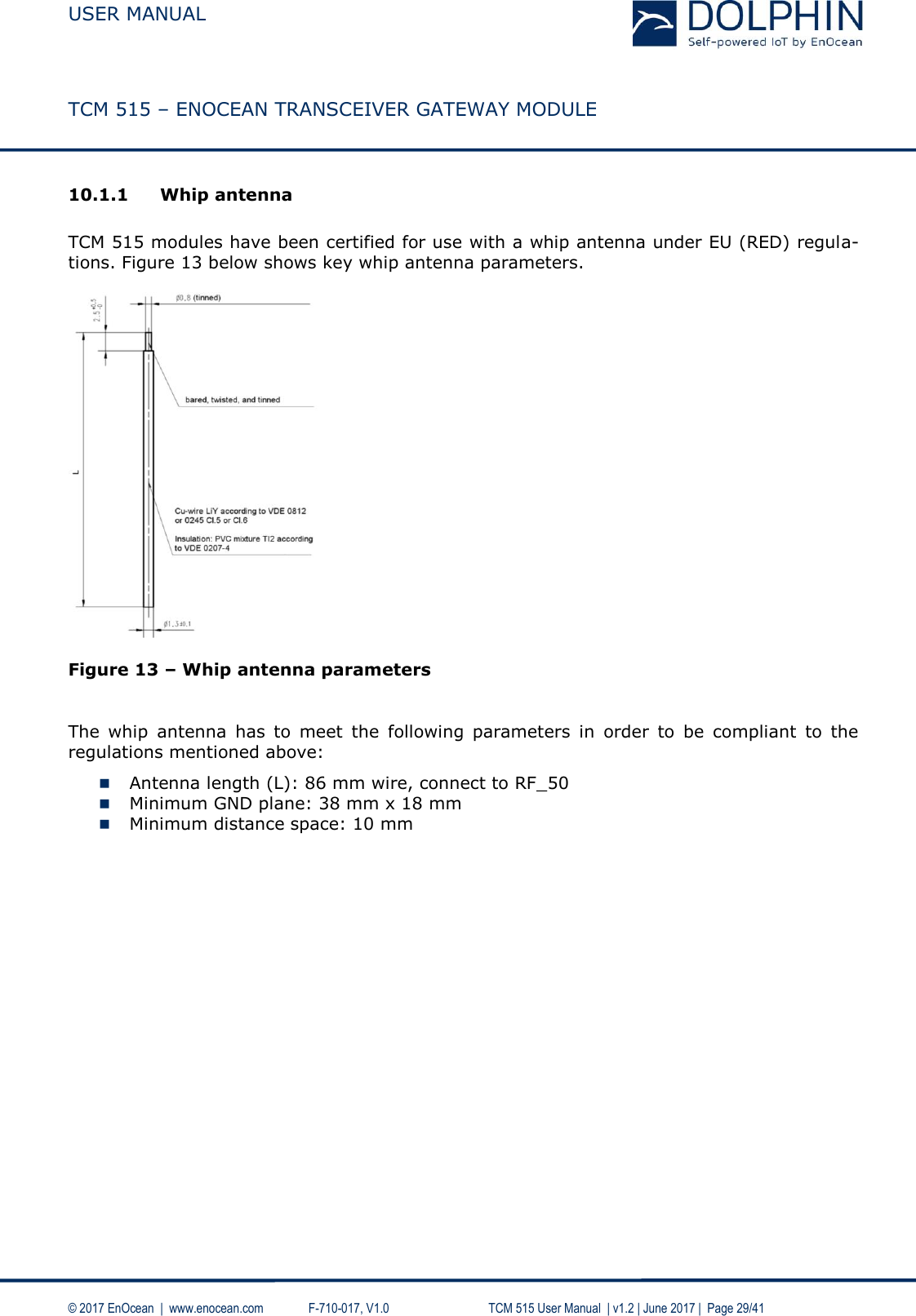
6.
Antenna Whip User Manual
7.
User Manual
User Manual
Navigation menu
Upload a User Manual
Namespaces
Wiki Guide
HTML
PDF
Info
Views
User Manual
Discussion / Help
Navigation