Endress and Hauser SE KG FMR25X Level Radar Transmitter User Manual Levelflex M
Endress and Hauser GmbH and Co Level Radar Transmitter Levelflex M
UserManual.wiki
>
Endress and Hauser SE KG
>
FMR25X User Manual
Users Manual
Navigation menu
Upload a User Manual
Namespaces
Wiki Guide
HTML
PDF
Info
Views
User Manual
Discussion / Help
Navigation

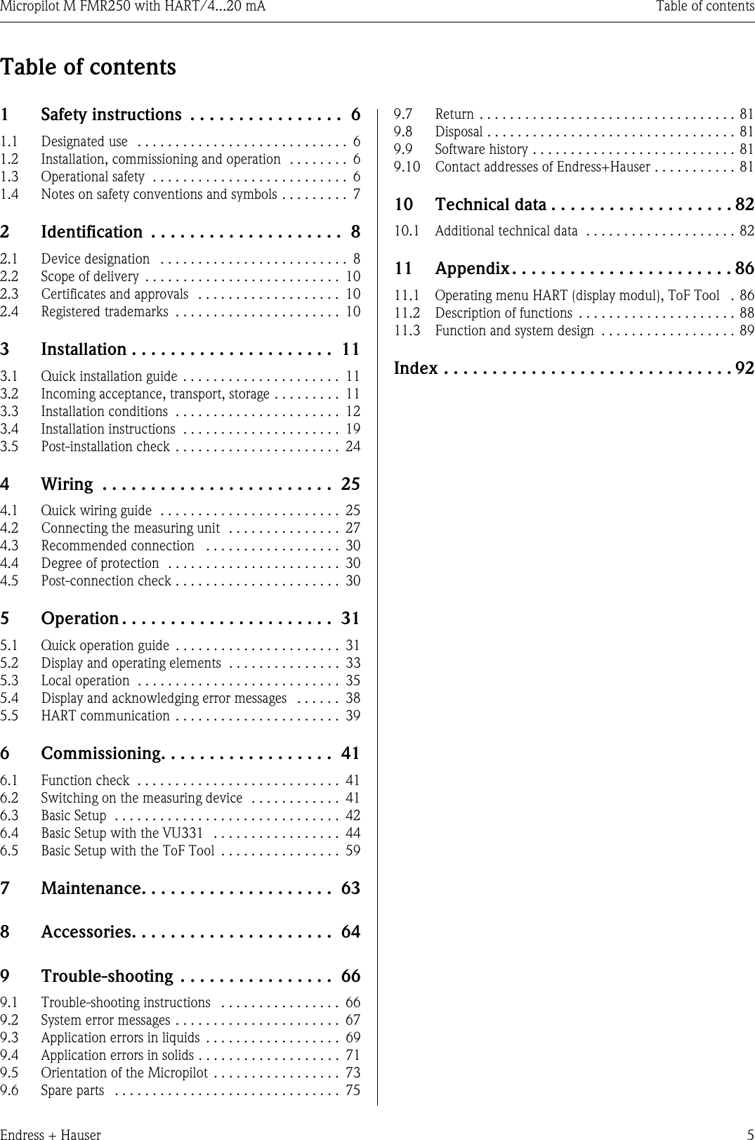
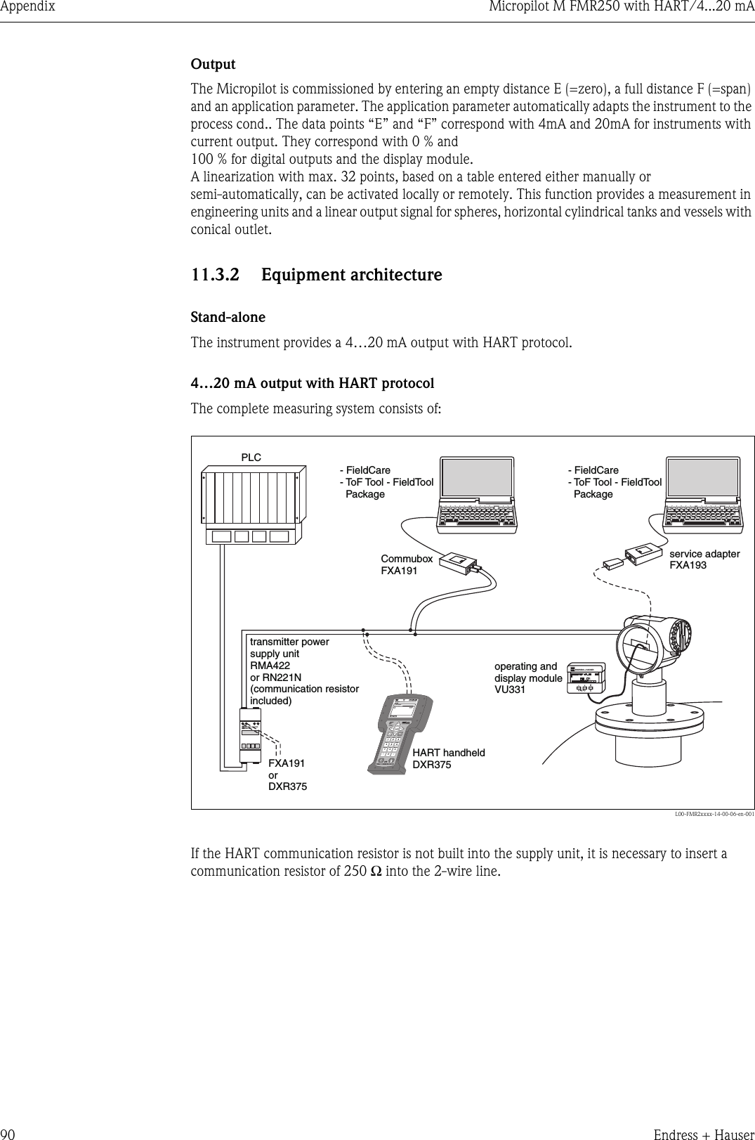
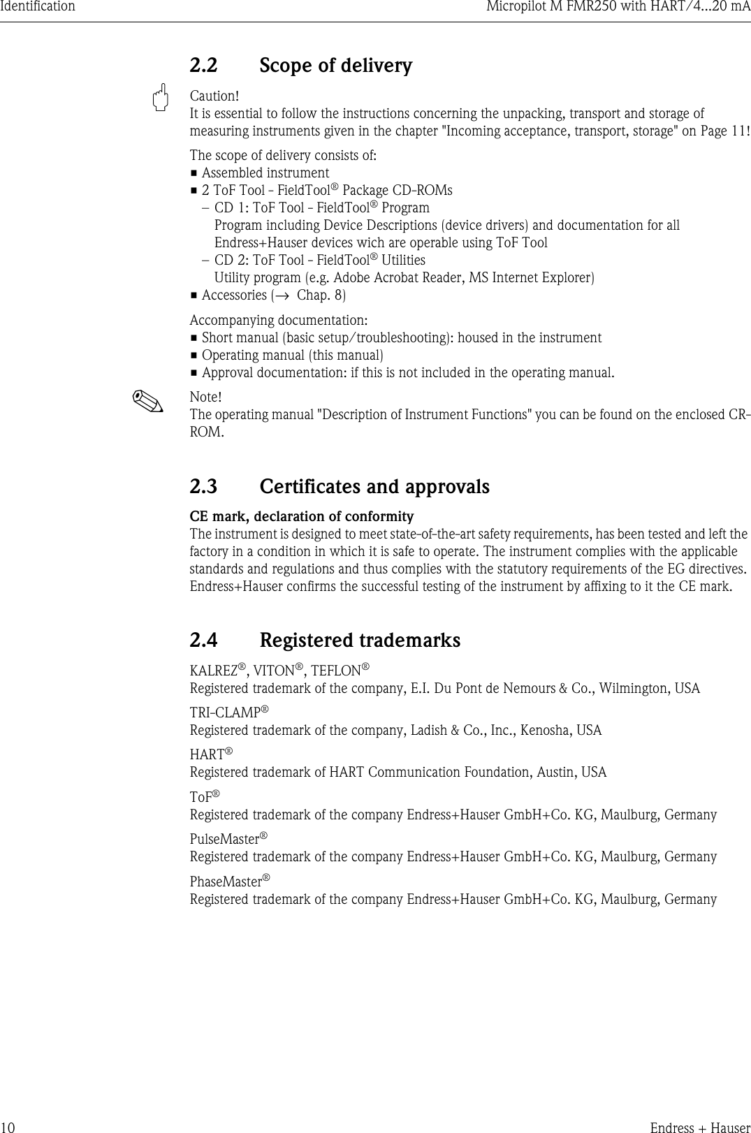
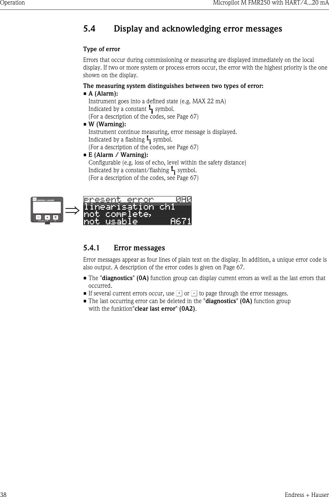
![Identification Micropilot M FMR250 with HART/4...20 mA8Endress + Hauser2 Identification2.1 Device designation2.1.1 NameplateThe following technical data are given on the instrument nameplate:L00-FMR2xxxx-18-00-00-en-001Fig. 1: Information on the nameplate of the Micropilot M (example)2.1.2 Ordering structureOrdering structure Micropilot M FMR25010 Approval:A Non-hazardous area1 ATEX II 1/2G EEx ia IIC T64 ATEX II 1/2G EEx d [ia] IIC T6G ATEX II 3G EEx nA II T6B ATEX II 1/2GD EEx ia IIC T6, Alu blind coverC ATEX II 1/2G EEx ia IIC T6, ATEX II 1/3DD ATEX II 1/2D, Alu blind coverE ATEX II 1/3DS FM IS-Cl.I/II/III Div.1 Gr.A-GT FM XP-Cl.I/II/III Div.1 Gr.A-GN CSA General PurposeU CSA IS-Cl.I/II/III Div.1 Gr.A-GV CSA XP-Cl.I/II/III Div.1 Gr.A-GYSpecial version20 Antenna:4 Horn 80mm/3"5 Horn 100mm/4"6 Parabolic 200mm/8"9 Special versionFMR250- Product designation (part 1)](https://usermanual.wiki/Endress-and-Hauser-SE-KG/FMR25X/User-Guide-565883-Page-8.png)
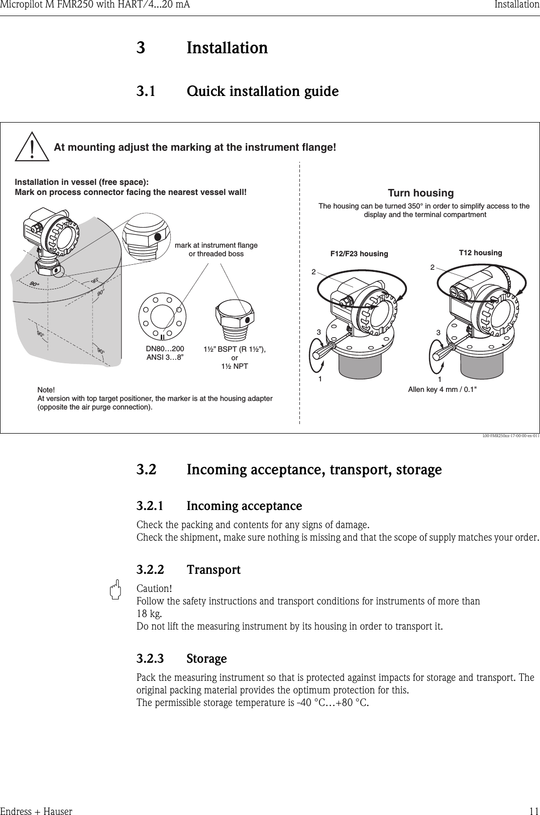
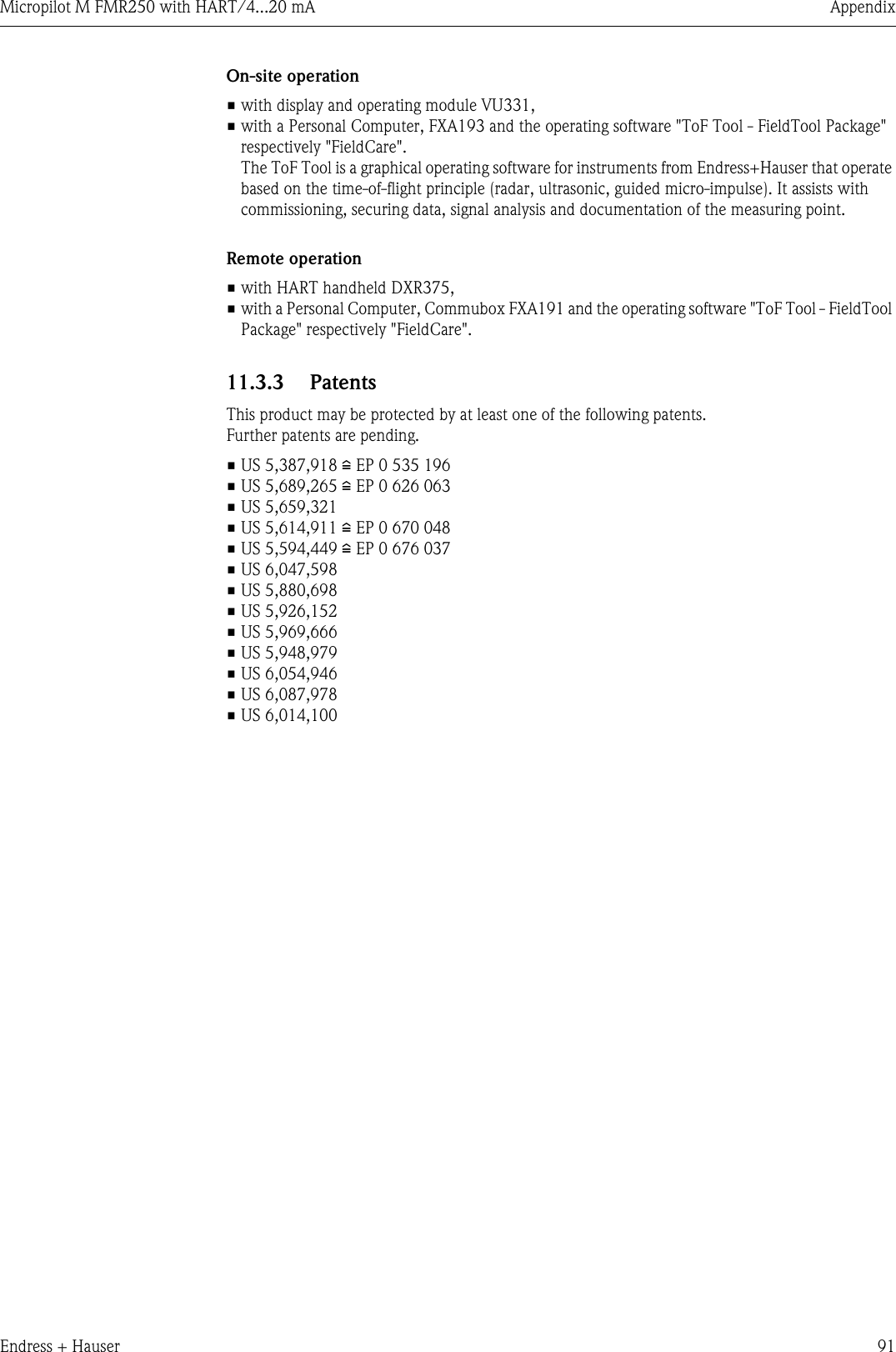
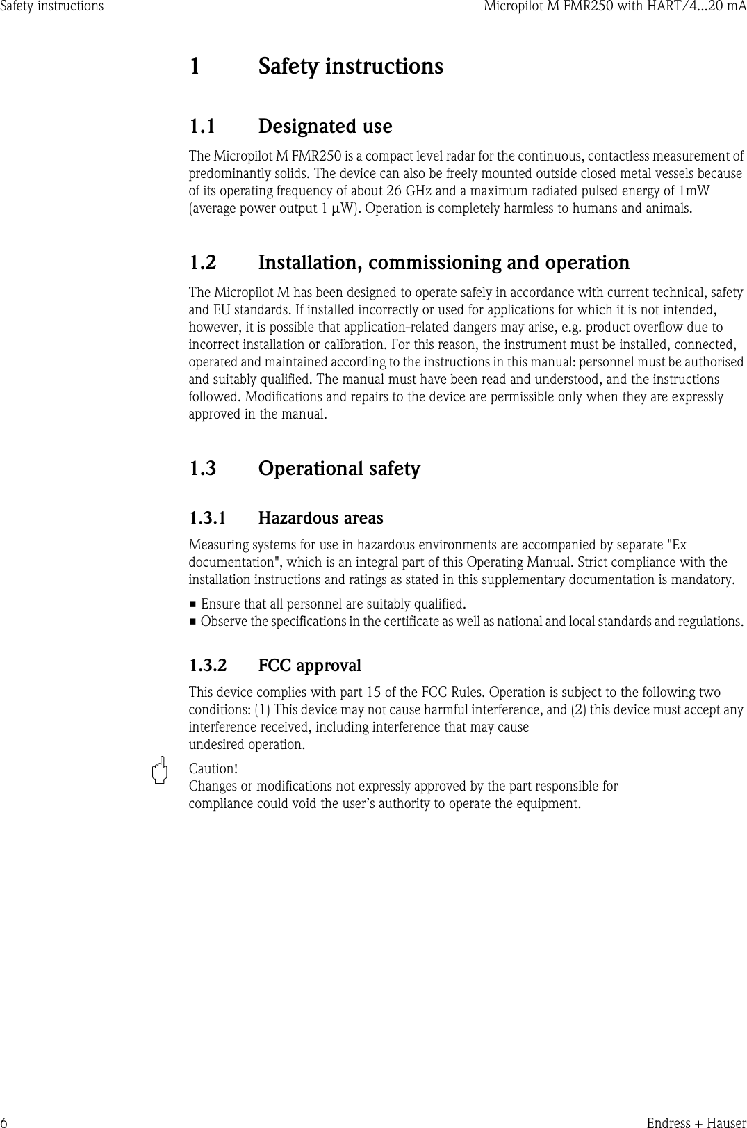
![Micropilot M FMR250 with HART/4...20 mA InstallationEndress + Hauser 13Micropilot M FMR250 - process connection, type of antennaL00-FMR250xx-06-00-00-en-005LLLL5050135401351351355050ØdØdØdØd250/450250/4507521180mm/3” 200mm/8”95 197282 195100mm/4”b [mm] b [mm]b [mm]DN 80 DN 803”20 1823.9200 185190.5L [mm] L [mm]d [mm] d [mm]D [mm] D [mm]D [mm]220 210228.620 1823.9DN 100 DN 1004”Ø D Ø 340 Ø 225 (DN100)340 (DN200)Ø43b8823Ø60Ø60Ø60Ø60Parabolic antennaHorn antennafor 10KFlangeFlange to JIS B2210for 150 lbsFlangeFlange to ANSI B16.5for PN10/16Antenna size Antenna sizeHorn antenna Parabolic antennaFlangeFlange to EN 1092-1 (agreeable to DIN 2527)F12 / T12 / F23 housingThreaded connectionBSPT (R 1 ½”)or 1 ½ NPT1 ½” Flange DN80…100or equivalentE+H UNI flange DN 200 Alignment unit withE+H UNI flange DN 100/200](https://usermanual.wiki/Endress-and-Hauser-SE-KG/FMR25X/User-Guide-565883-Page-13.png)
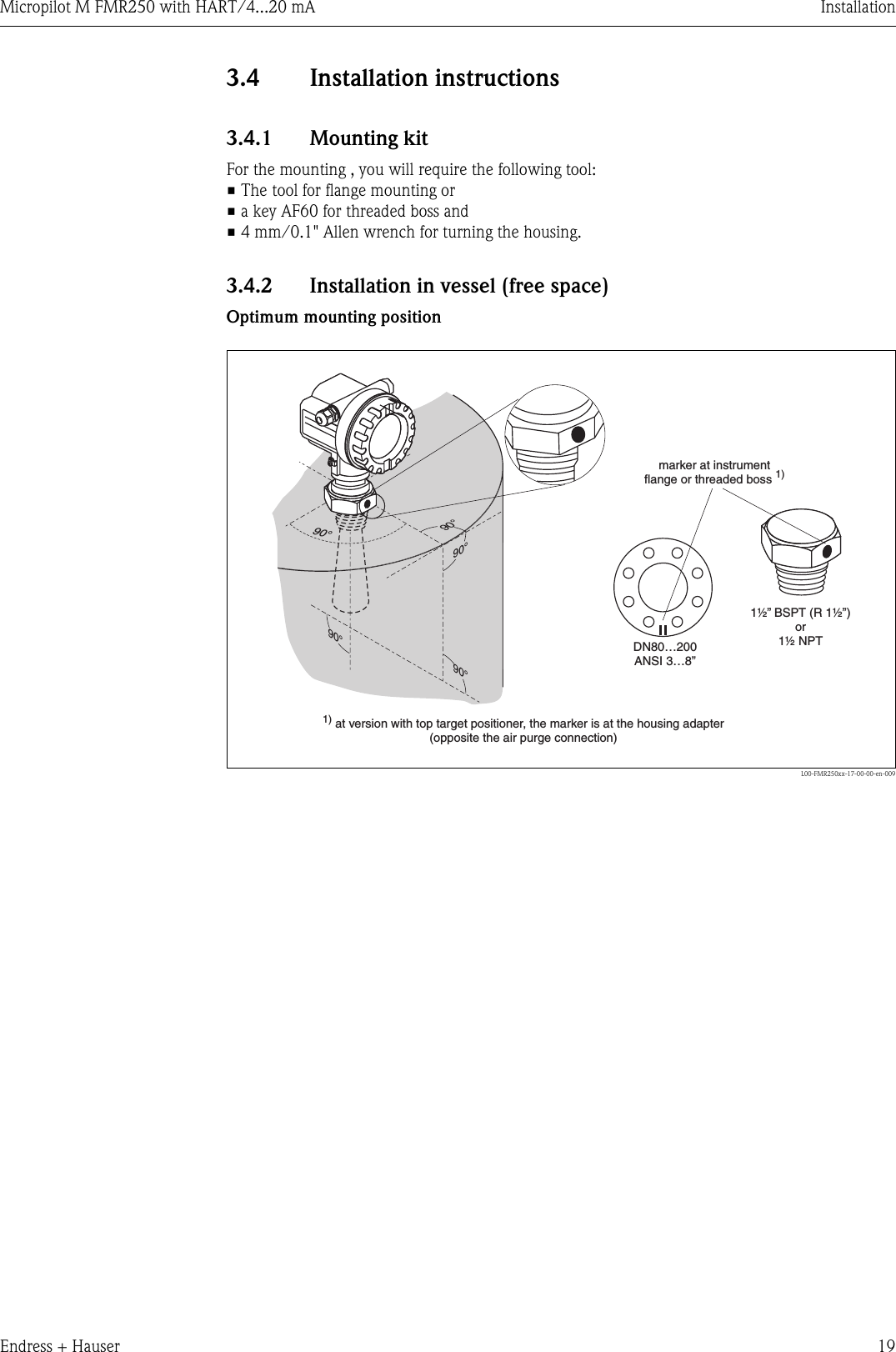
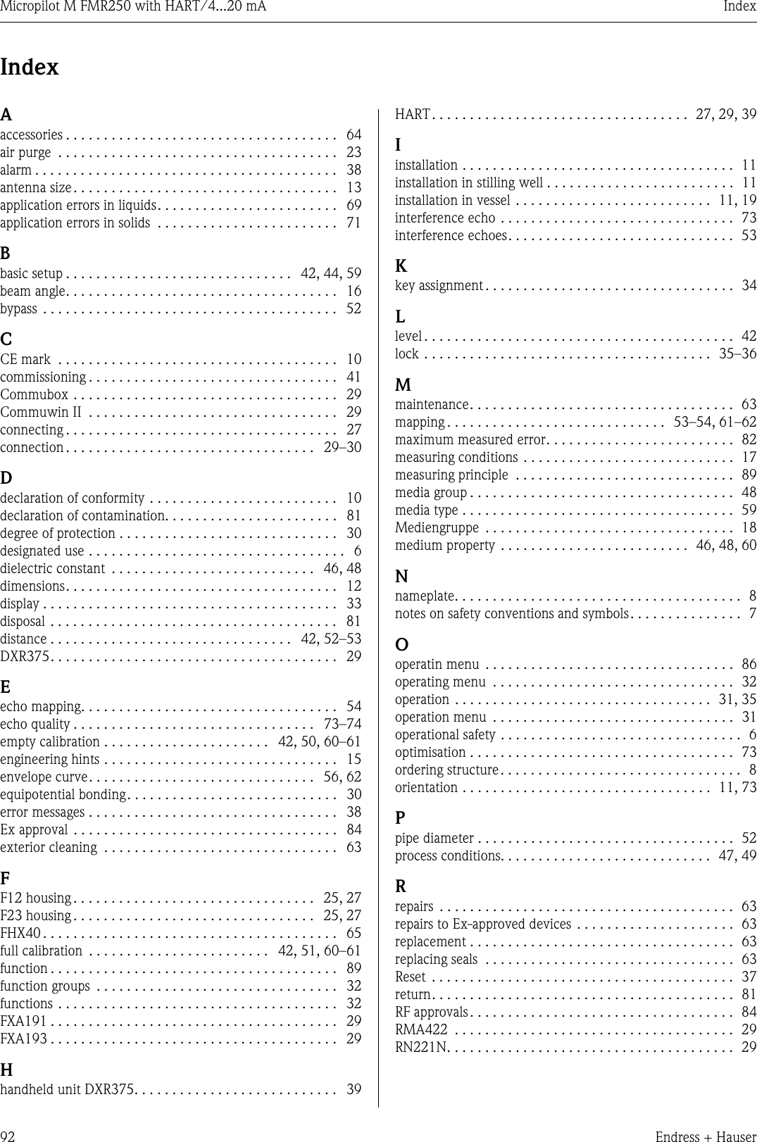
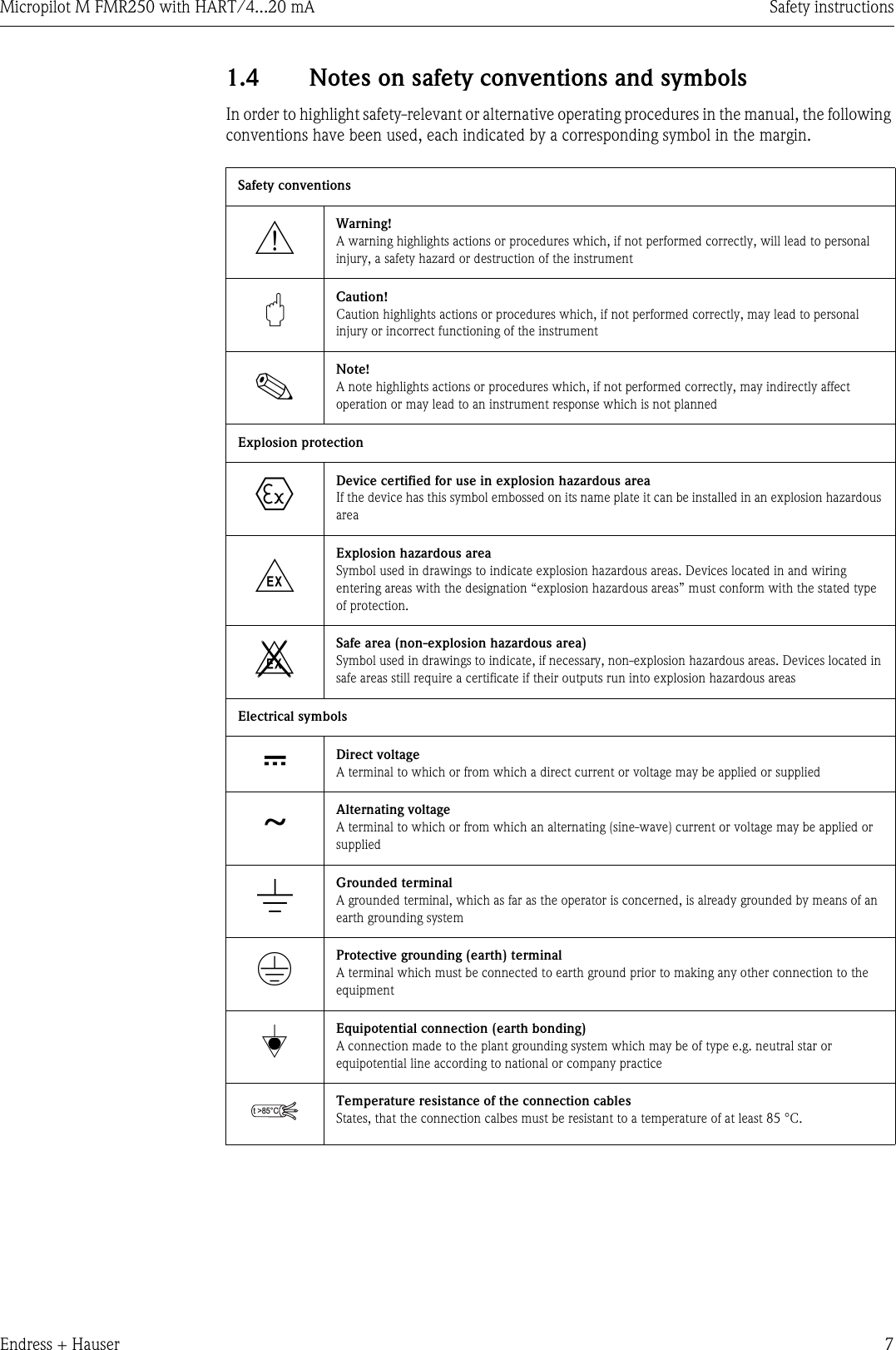
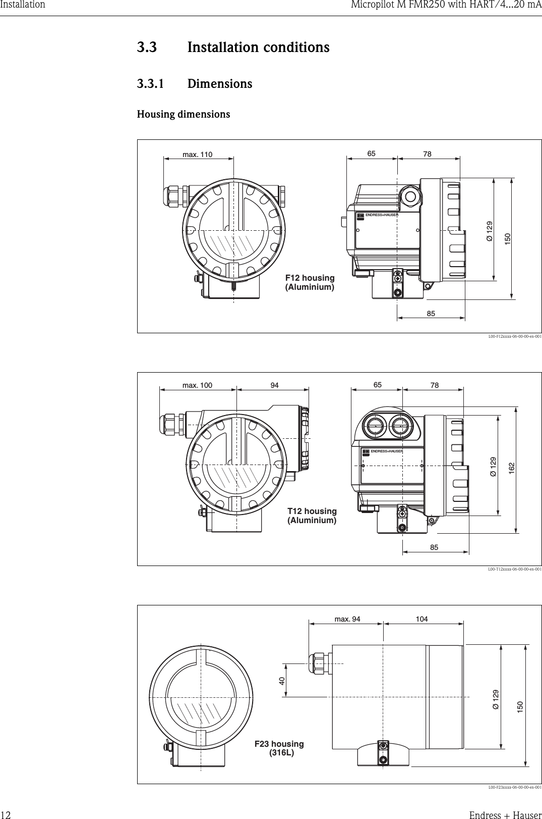
![Installation Micropilot M FMR250 with HART/4...20 mA20 Endress + HauserStandard installation FMR250 with horn antenna• Observe installation instructions on Page 15.• Marker is aligned towards vessel wall.• The marker is always exactly in the middle between two bolt-holes in the flange.• After mounting, the housing can be turned 350° in order to simplify access to the display and the terminal compartment.• The horn antenna should protrude from the nozzle. If necessary, choose version with antenna extension (see Page 13).If this is not possible for mechanical reasons, nozzle heights up to 500 mm can be accepted.Note!Please contact Endress+Hauser for application with higher nozzle.•Vertical horn antenna.Ideally, the horn antenna should be installed vertically.To avoid interference reflections or for optimum alignment within the vessel, the FMR250 with optional top target positioner can be swiveled by 15° in all directions.L00-FMR250xx-17-00-00-en-004HØDAntenna size 80 mm / 3" 100 mm / 4"D [mm / inch] 75 / 3 95 / 3.7H [mm / inch](without antenna extension) < 260 / < 10.2 < 330 / < 12.9](https://usermanual.wiki/Endress-and-Hauser-SE-KG/FMR25X/User-Guide-565883-Page-20.png)
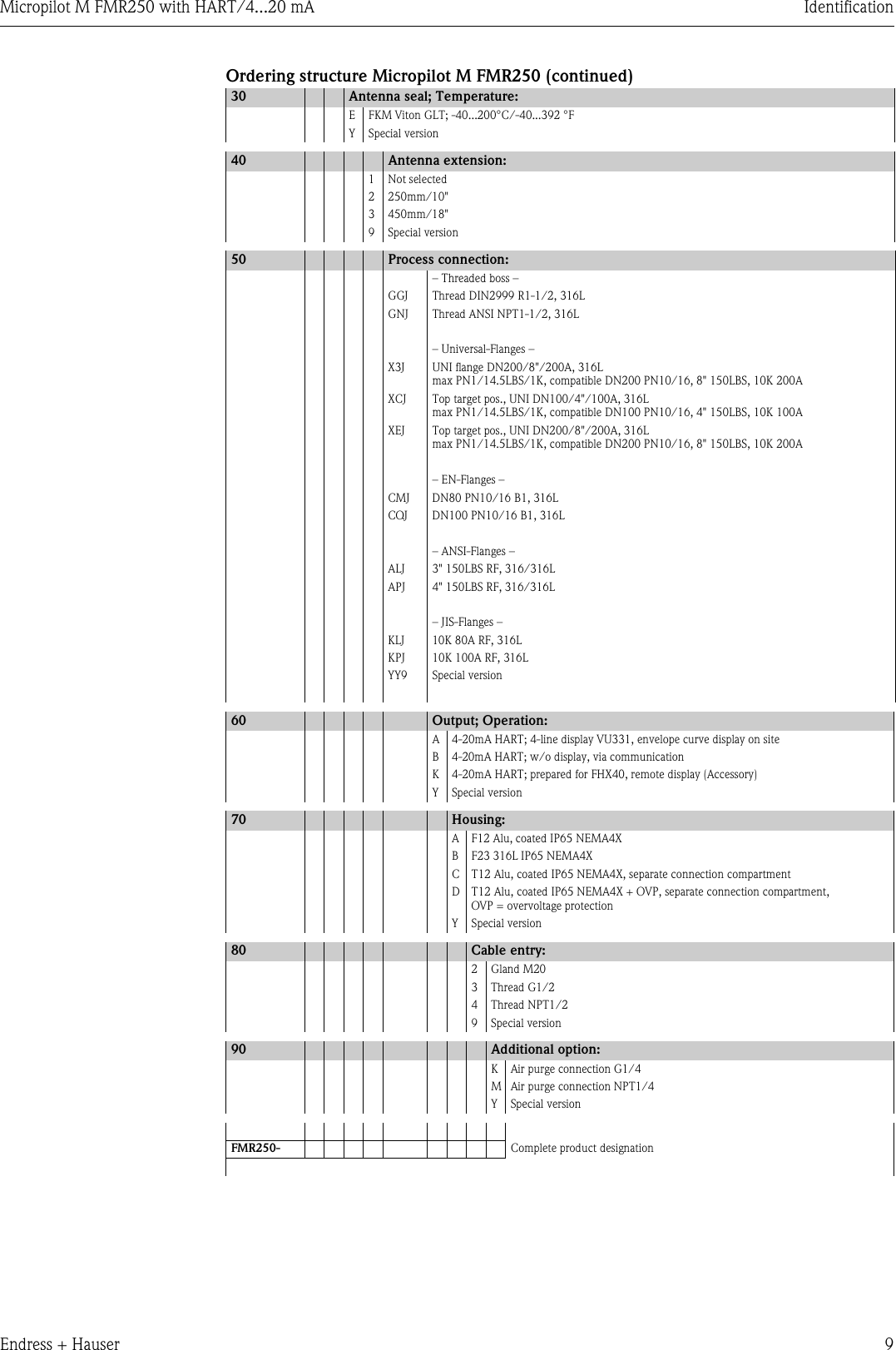
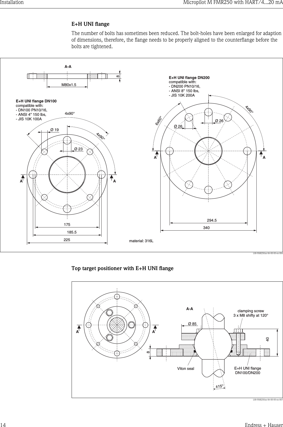
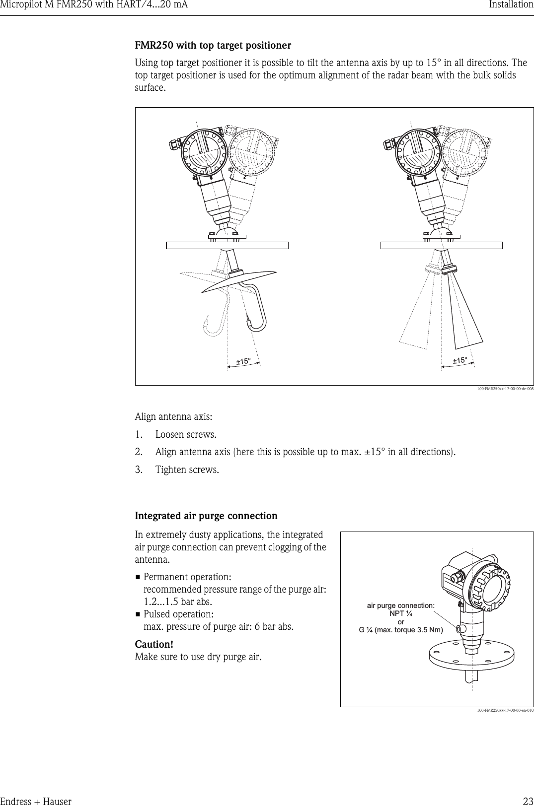
![Micropilot M FMR250 with HART/4...20 mA InstallationEndress + Hauser 21Standard installation FMR250 with parabolic antenna• Observe installation instructions on Page 15.• Marker is aligned towards vessel wall.• The marker is always exactly in the middle between two bolt-holes in the flange.• After mounting, the housing can be turned 350° in order to simplify access to the display and the terminal compartment.• Ideally the parabolic antenna should protrude from the nozzle (1). If necessary, choose version with antenna extension (see Page 13).Particularly when using the top target positioner, please ensure that the parabolic reflector is protruding from the nozzle/roof so as not to inhibit alignment.Note!For application with higher nozzle install parabolic antenna completely in the nozzle (2), including RF-wave guide (3).•Vertical parabolic antenna.Ideally, the parabolic antenna should be installed vertically.To avoid interference reflections or for optimum alignment within the vessel, the FMR250 with optional top target positioner can be swiveled by 15° in all directions.L00-FMR250xx-17-00-00-en-005HØD123Antenna size 200 mm / 8"D [mm / inch] 197 / 7.75H [mm / inch](without antenna extension) < 50 / < 1.96](https://usermanual.wiki/Endress-and-Hauser-SE-KG/FMR25X/User-Guide-565883-Page-21.png)
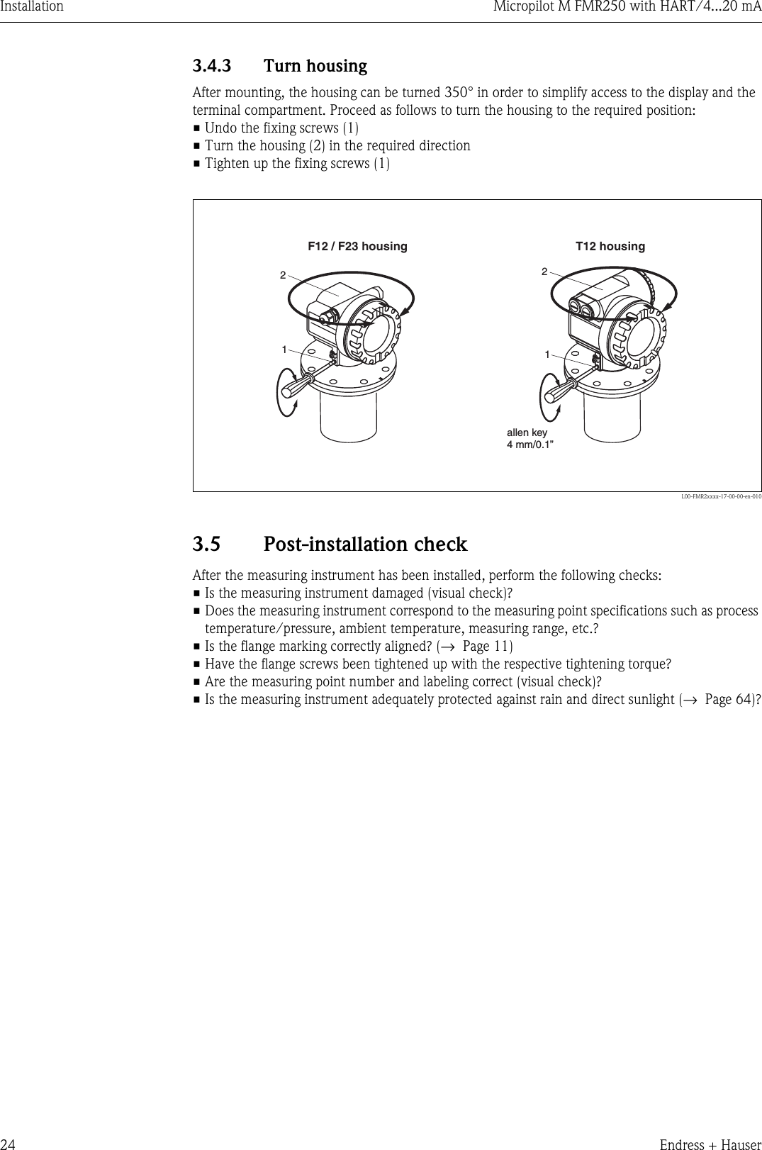
![Installation Micropilot M FMR250 with HART/4...20 mA22 Endress + HauserExamples for installation with small flange (< parabolic reflector)L00-FMR250xx-17-00-00-en-007HDD [mm]200mm/8”197< 50H [mm] 1)for installationin nozzleyou can dismantlethe parabolic reflector4 boltsstandard installationnozzleAntenna sizeCaution!At hinged flanges, the length of the antennamust be taken into account!1) without antenna extension](https://usermanual.wiki/Endress-and-Hauser-SE-KG/FMR25X/User-Guide-565883-Page-22.png)
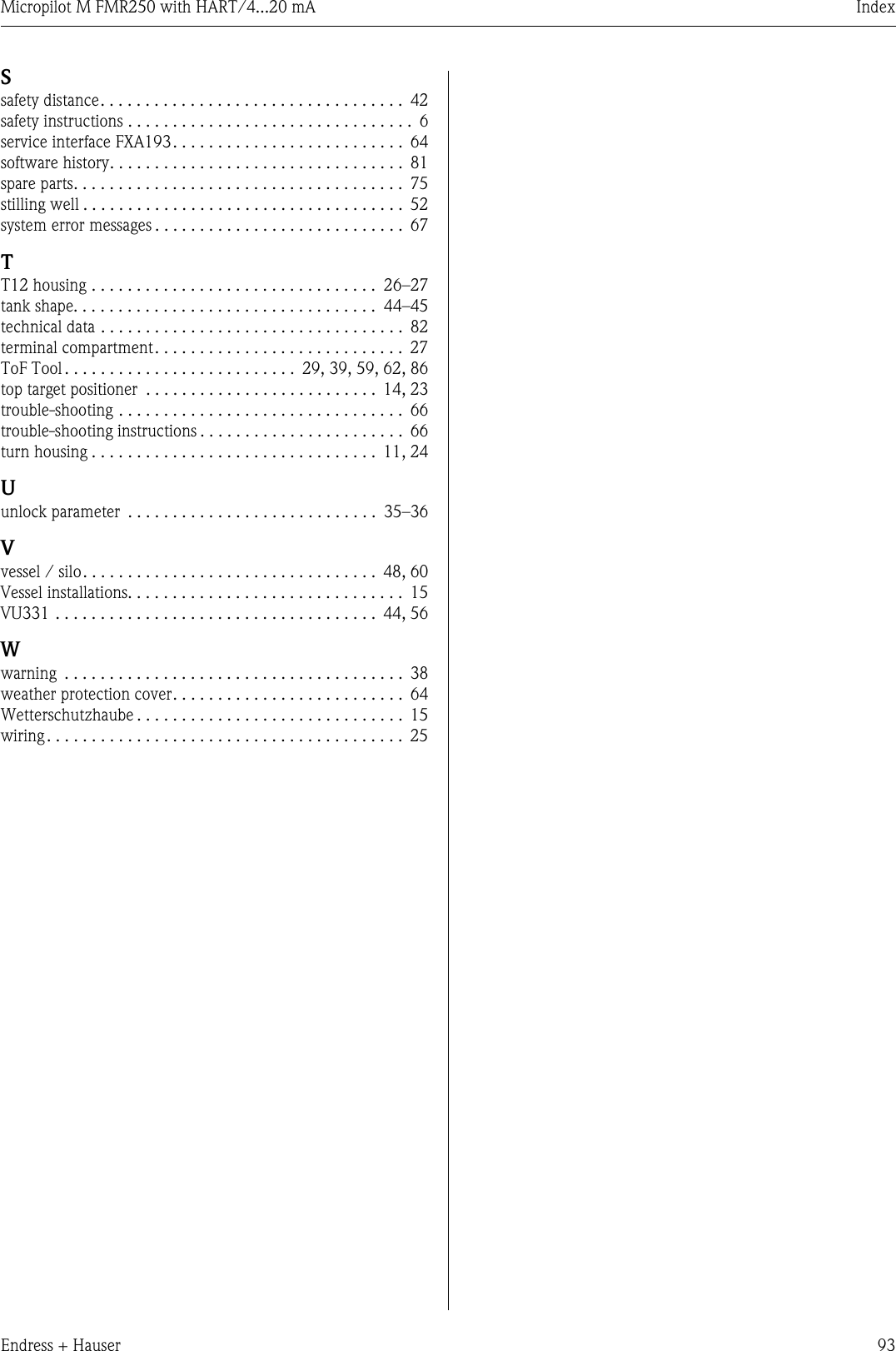
![Micropilot M FMR250 with HART/4...20 mA AccessoriesEndress + Hauser 65Remote display FHX40DimensionsL00-FMxxxxxx-00-00-06-en-003Technical data and product structure:ENDRESS+HAUSERENDRESS+HAUSERIP 65Order Code:Ser.-No.:Order Code:Ser.-No.:MessbereichMeasuring rangeMessbereichMeasuring rangeU 16...36V DC4...20 mAU 16...36 V DC4...20 mAmax.20 mmax. 20 mMade in Germany MaulburgMade in Germany MaulburgT>70°C :At >85°CT>70°C :At >85°C826,3106122120max. 80min. 3096881608,5118180Micropilot MLevelflex MProsonic MGammapilot MSeparate housingFHX 40 (IP 65)CableHWDWall-mounting(without mounting bracket)Pipe-mounting(mounting bracket and platesupplied optionally,s. product structure)pipeMax. cable length 20 m (65 ft)Temperature range -30 °C...+70 °C (-22 °F...158 °F)Degree of protection IP65 acc. to EN 60529 (NEMA 4)Material for housing Alloy of Aluminium AL Si 12Dimensions [mm] / [inch] 122x150x80 (HxWxD) / 4.8x5.9x3.2Approval:A Nn-hazardous area1 ATEX II 2 G EEx ia IIC T6, ATEX II 3DS FM IS Cl.I Div.1 Gr.A-DU CSA IS Cl.I Div.1 Gr.A-DN CSA General PurposeCable length:1 20m/65ftAdditional option:A Basic versionB Mounting bracket, pipe 1"/ 2"FHX40 - Complete product designation](https://usermanual.wiki/Endress-and-Hauser-SE-KG/FMR25X/User-Guide-565883-Page-65.png)


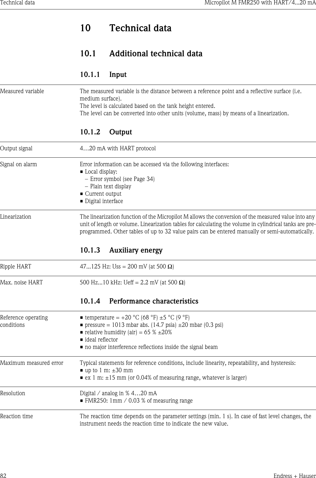
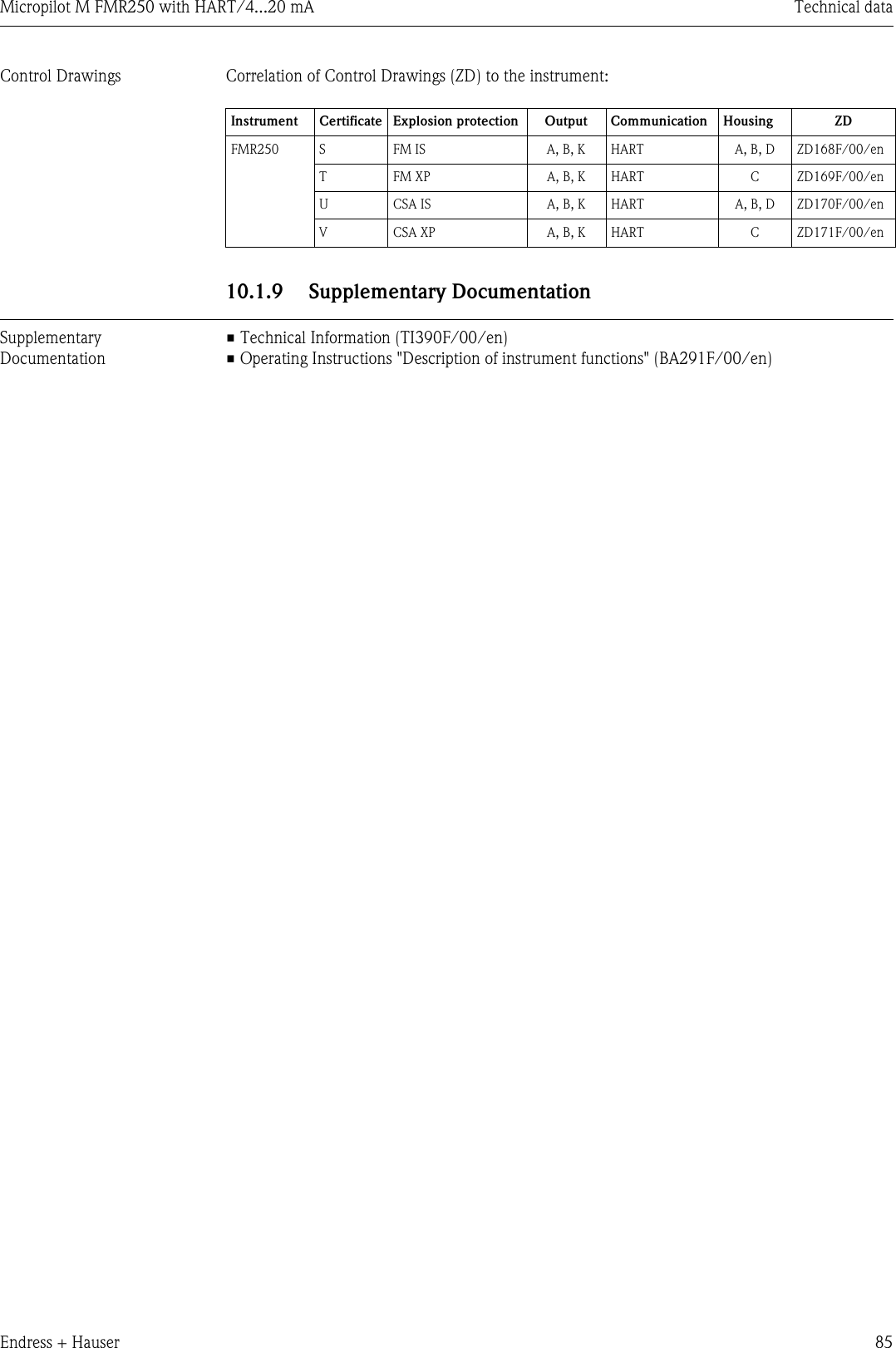
![Technical data Micropilot M FMR250 with HART/4...20 mA84 Endress + Hauser10.1.6 Operating conditions: ProcessDielectric constant • in free space: εr ≥ 1.610.1.7 Mechanical constructionWeight • F12/T12 housing: approx 6 kg + weight of flange• F23 housing: approx 9.4 kg + weight of flange10.1.8 Certificates and approvalsCE approval The measuring system meets the legal requirements of the EC-guidelines. Endress+Hauser confirms the instrument passing the required tests by attaching the CE-mark.RF approvals R&TTE, FCCExternal standards and guidelinesEN 60529Protection class of housing (IP-code)EN 61010Safety regulations for electrical devices for measurement, control, regulation and laboratory use.EN 61326Emissions (equipment class B), compatibility (appendix A - industrial area)NAMURStandards committee for measurement and control in the chemical industryEx approval Correlation of safety instructions (XA) and certificates (ZE) to the instrument:Seal / Temperature E FKM Viton GLT, -40 °C...+200 °C (-40 °F...+392 °F)Pressure -1 ...16 bar (...232 psi), E+H UNI flange: -1...1 bar (...14.5 psi)Antenna cone PEEKWetted parts PEEK, seal and 316 L/1.4404/1.4435Optional: top target positioner ±15°, seal: FKM Viton GLTInstrument Certificate Explosion protection Output Communication Housing PTB 04 ATEX XAFMR250 A Non-hazardous area A, B, K HART — — —1 ATEX II 1/2G EEx ia IIC T6 A, B, K HART A, B, D in preparation XA313F-A4 ATEX II 1/2G EEx d [ia] IIC T6 A, B, K HART C in preparation XA314F-AG ATEX II 3G EEx nA II T6 A, B, K HART in preparationB ATEX II 1/2GD EEx ia IIC T6, Alu blind cover A, B, K HART A, B, D in preparation XA312F-AC ATEX II 1/2G EEx ia IIC T6ATEX II 1/3DA, B, K HART A, B, D in preparation XA312F-AD ATEX II 1/2D, Alu blind cover A, B, K HART C in preparation XA315F-AE ATEX II 1/3D A, B, K HART C in preparation XA315F-A](https://usermanual.wiki/Endress-and-Hauser-SE-KG/FMR25X/User-Guide-565883-Page-84.png)