Endress and Hauser SE KG FMR5XKF K-Band Level Probing Radar User Manual Micropilot FMR56 FMR57
Endress and Hauser GmbH and Co K-Band Level Probing Radar Micropilot FMR56 FMR57
Contents
- 1. user manual I
- 2. user manual II
- 3. user manual III
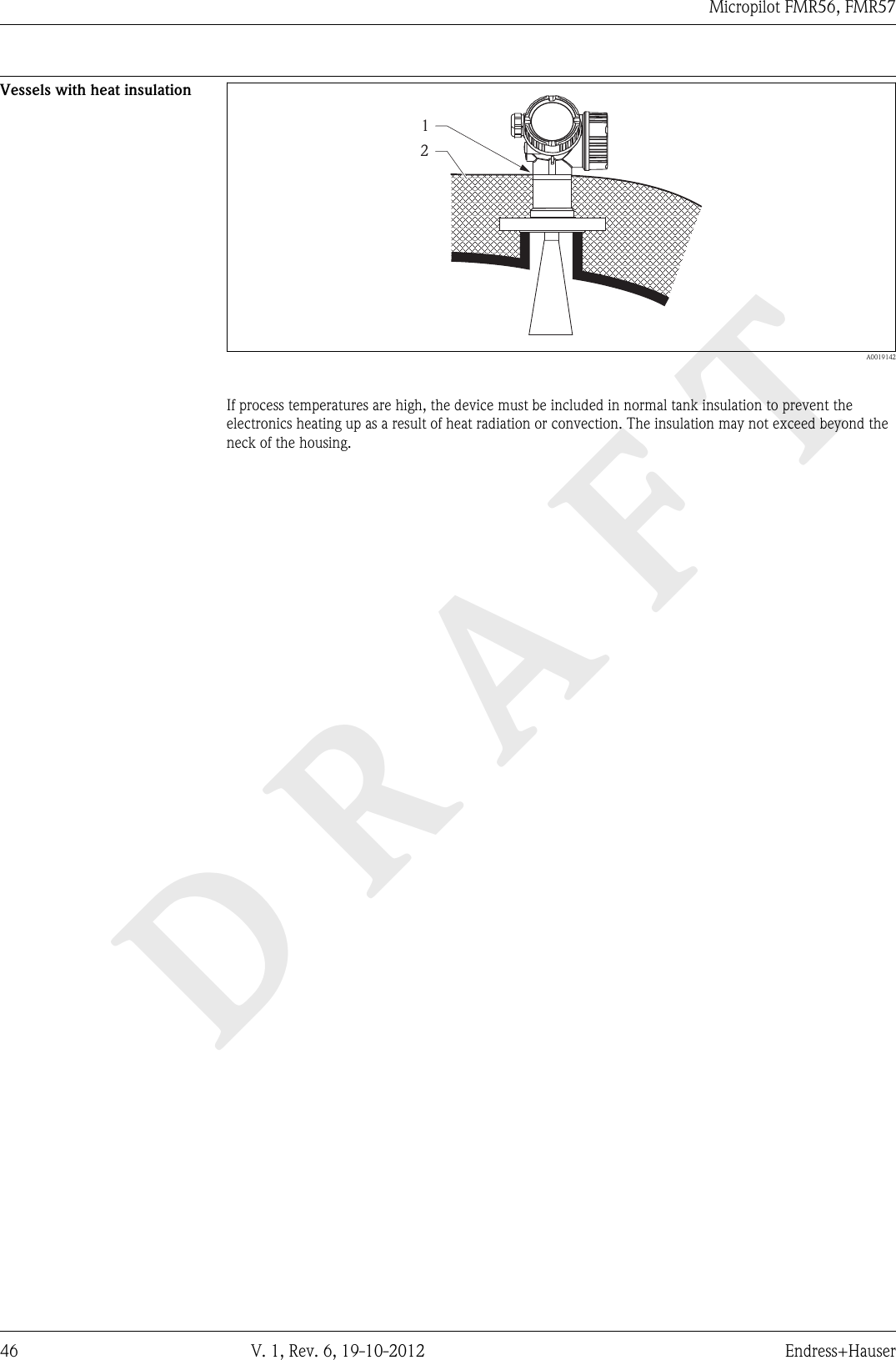
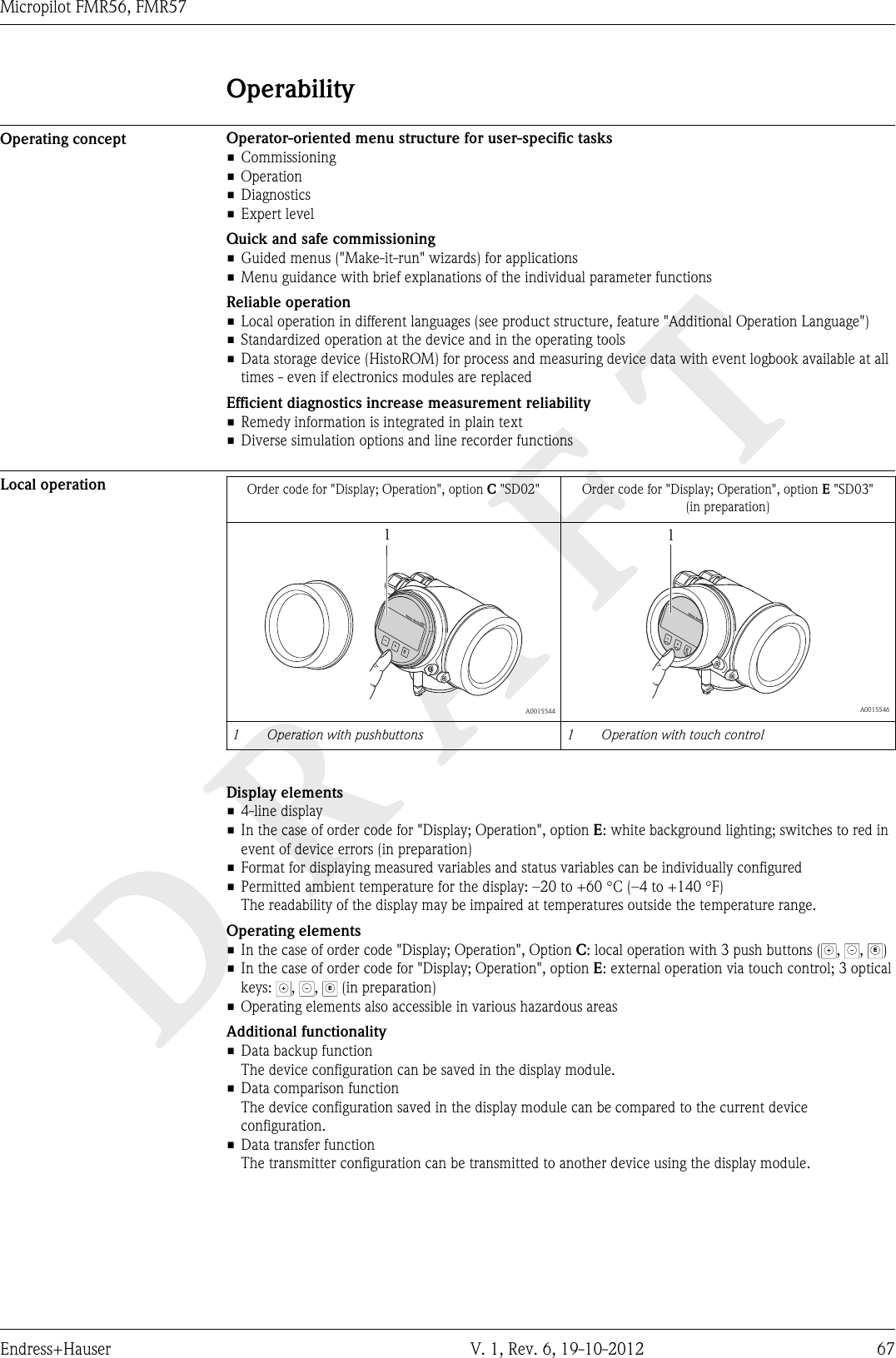
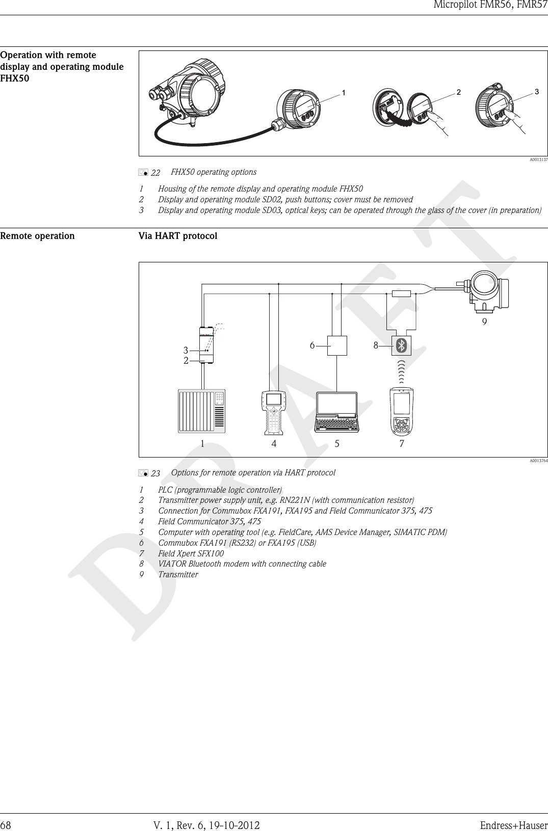
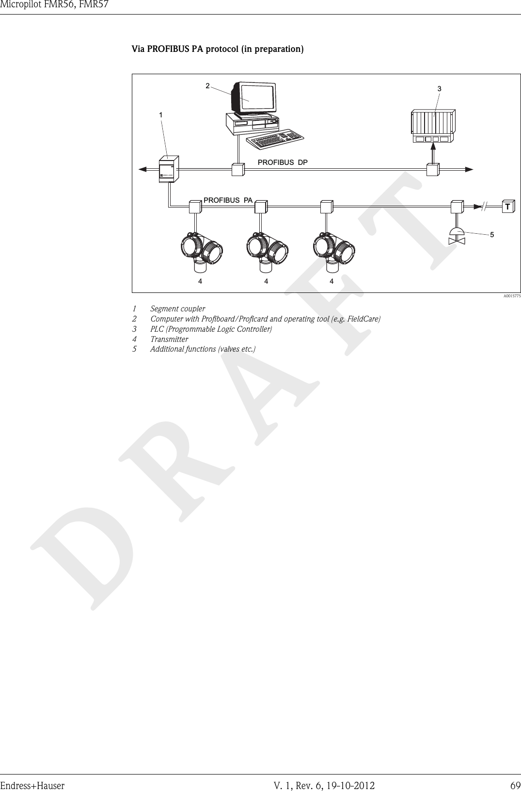
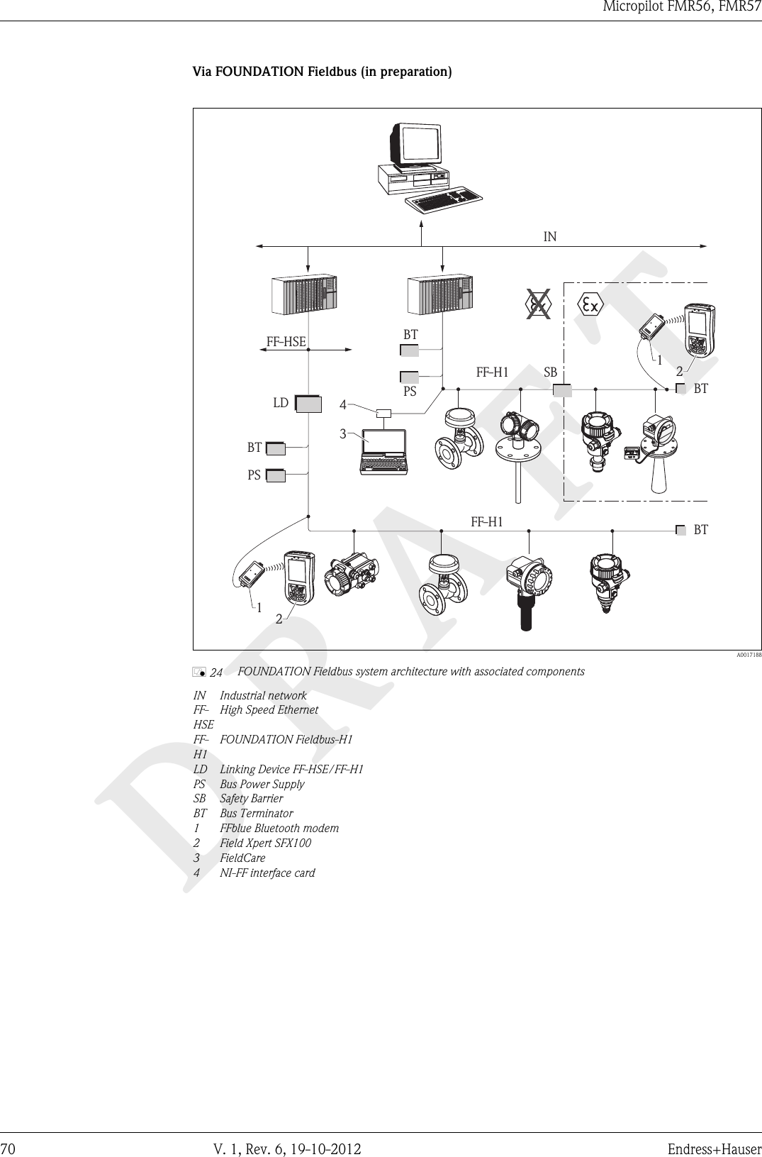
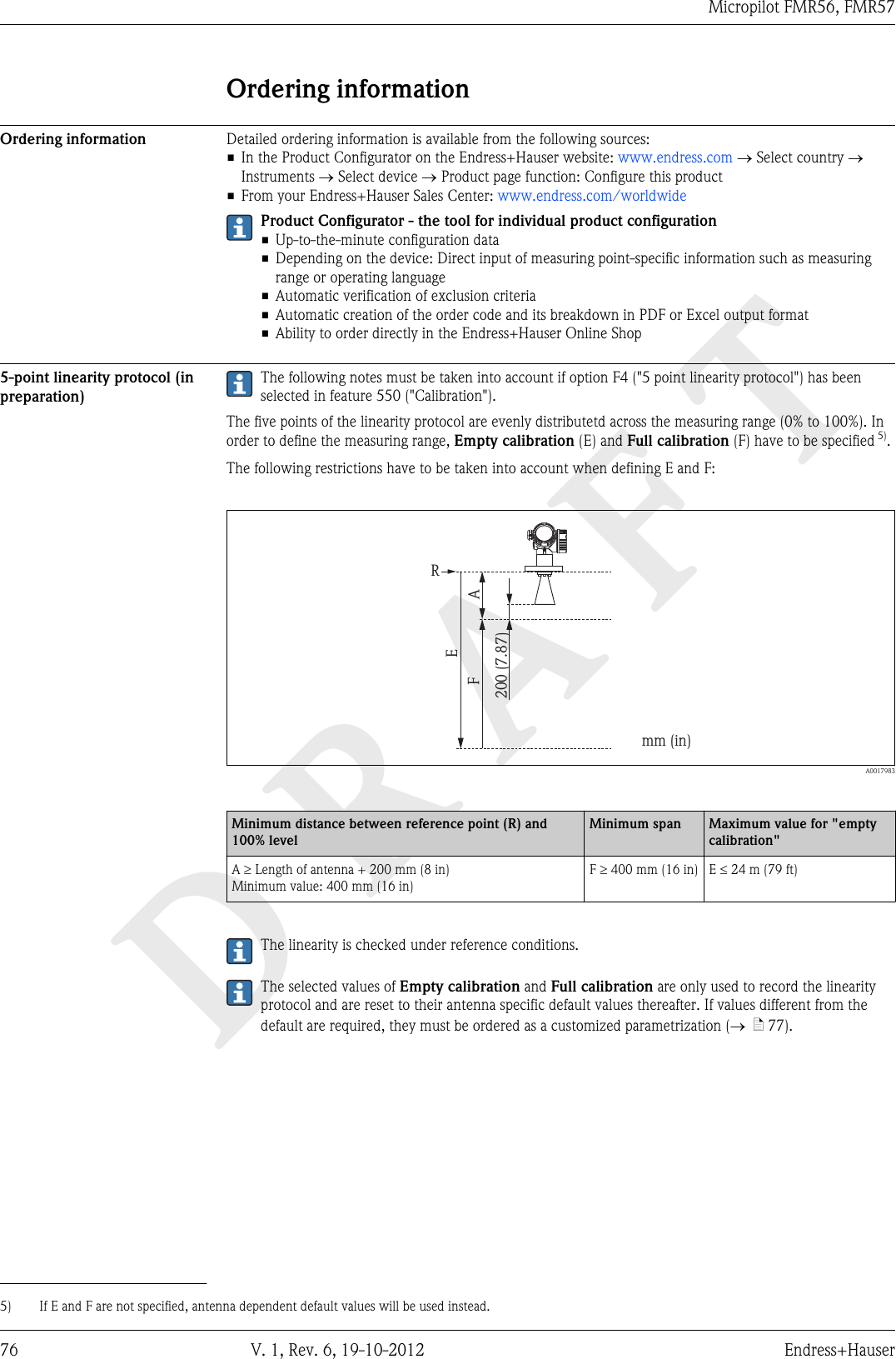
user manual III

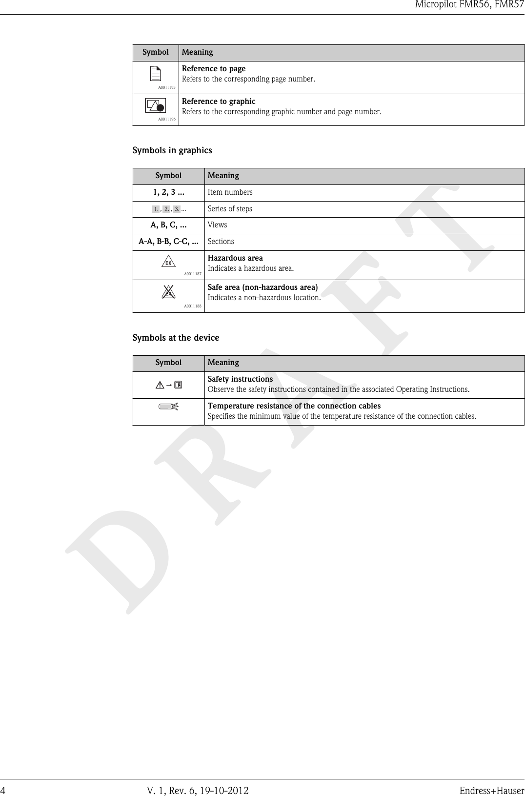
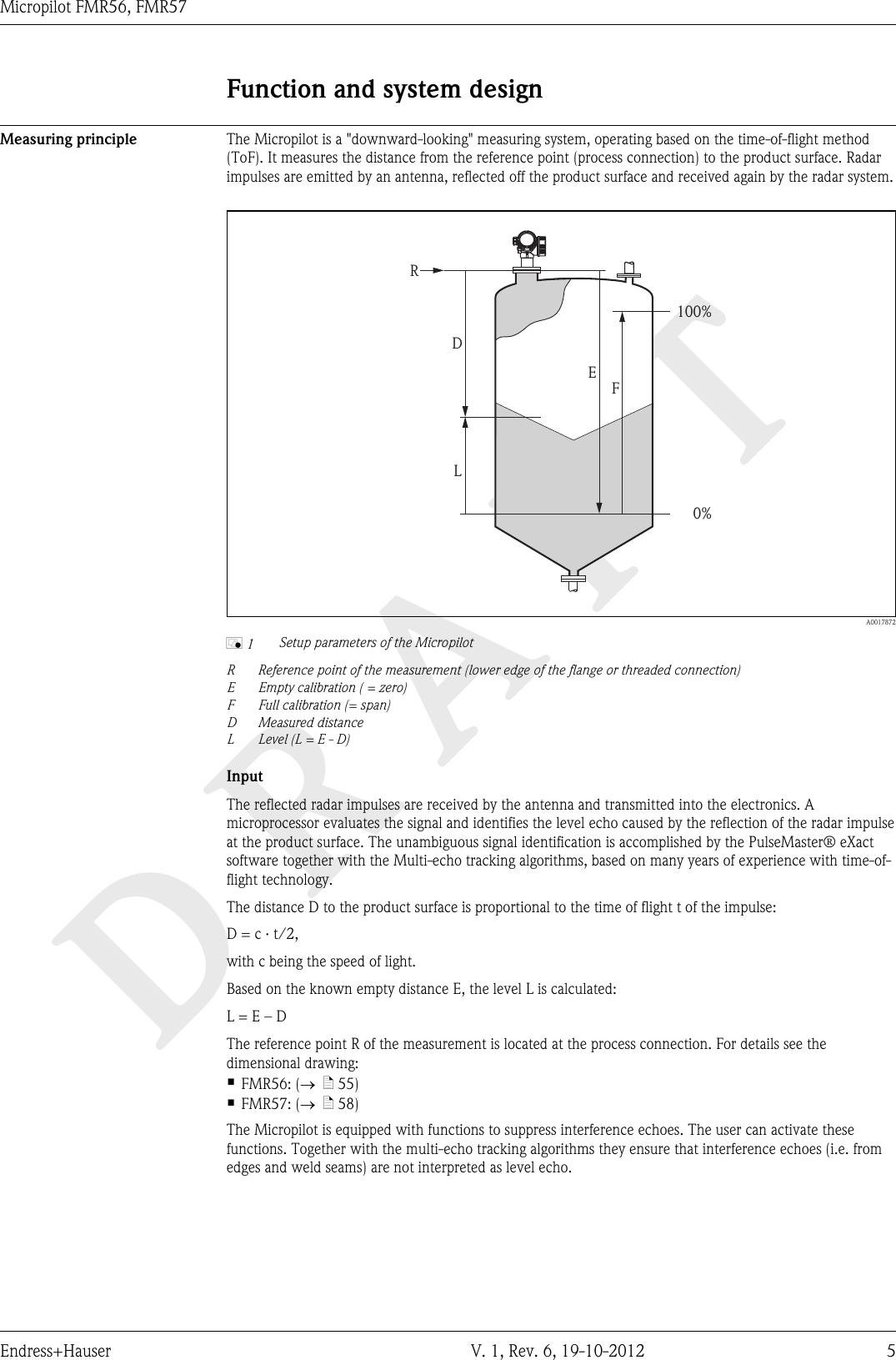
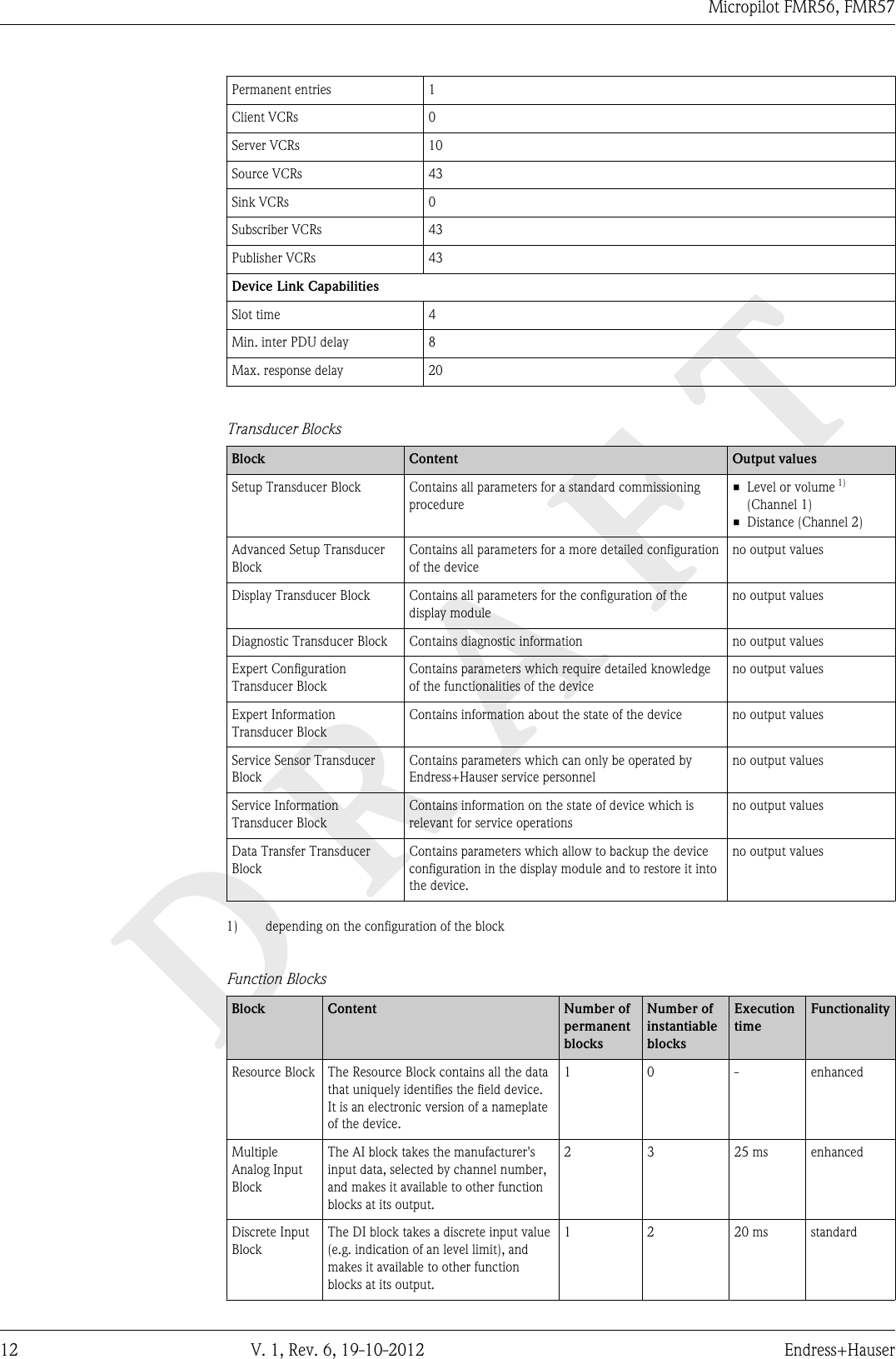
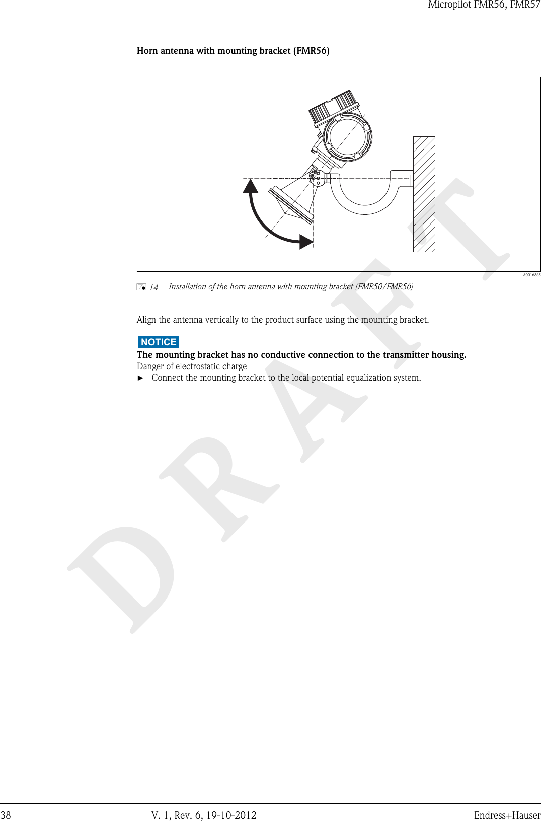
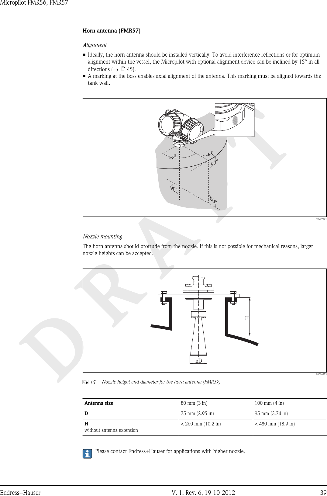
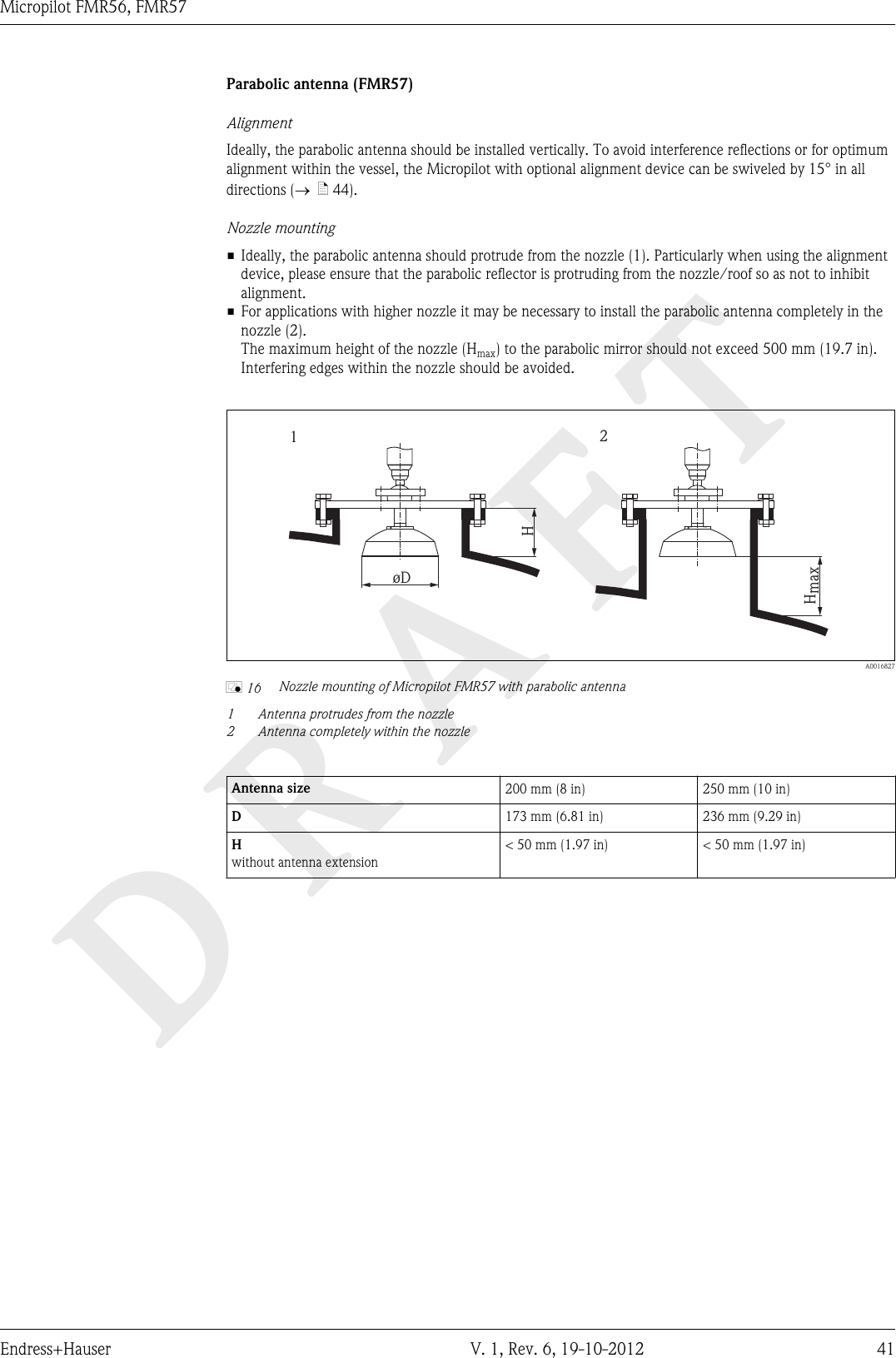
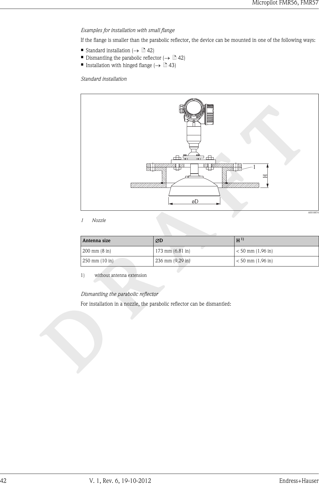
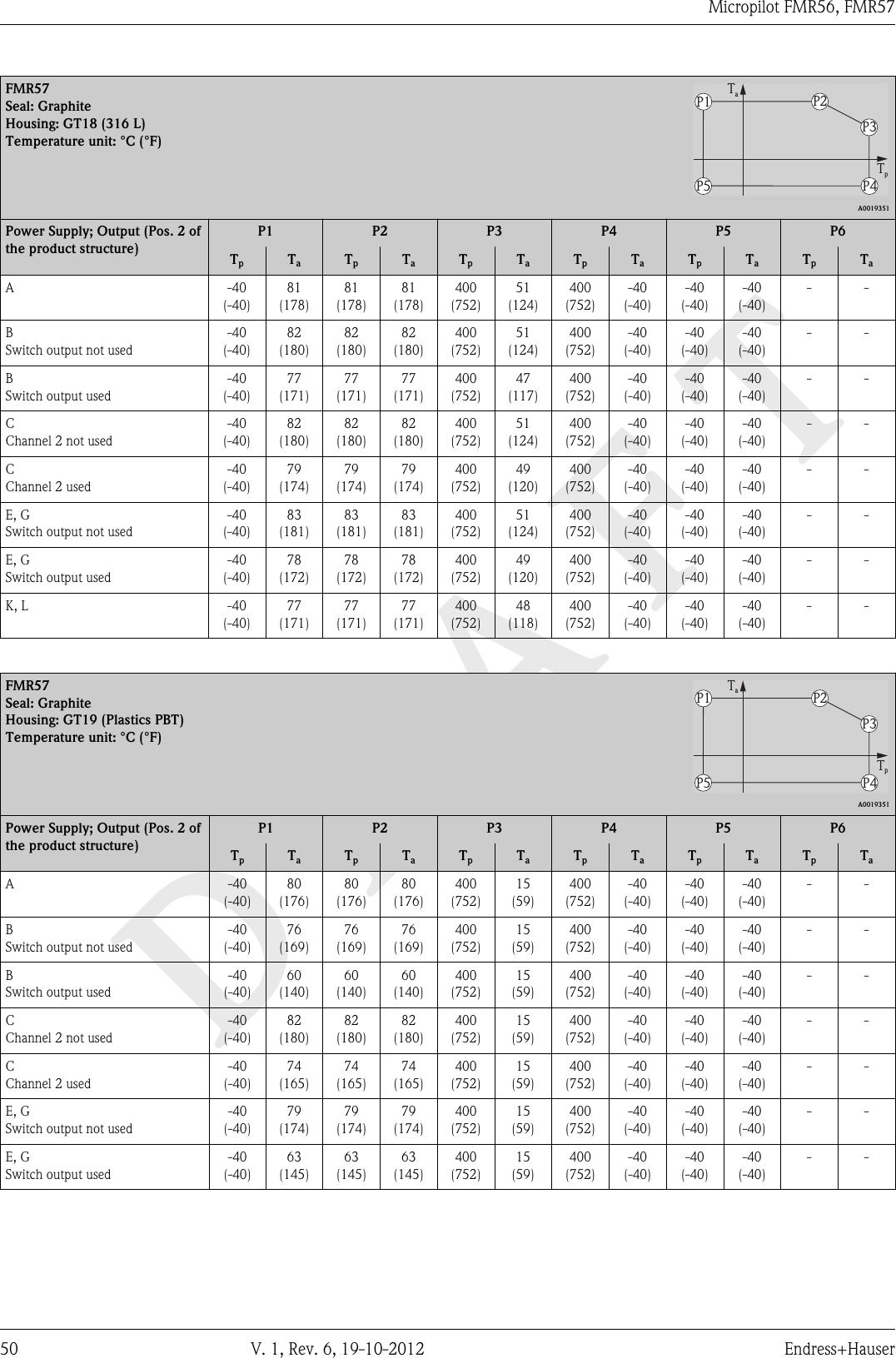
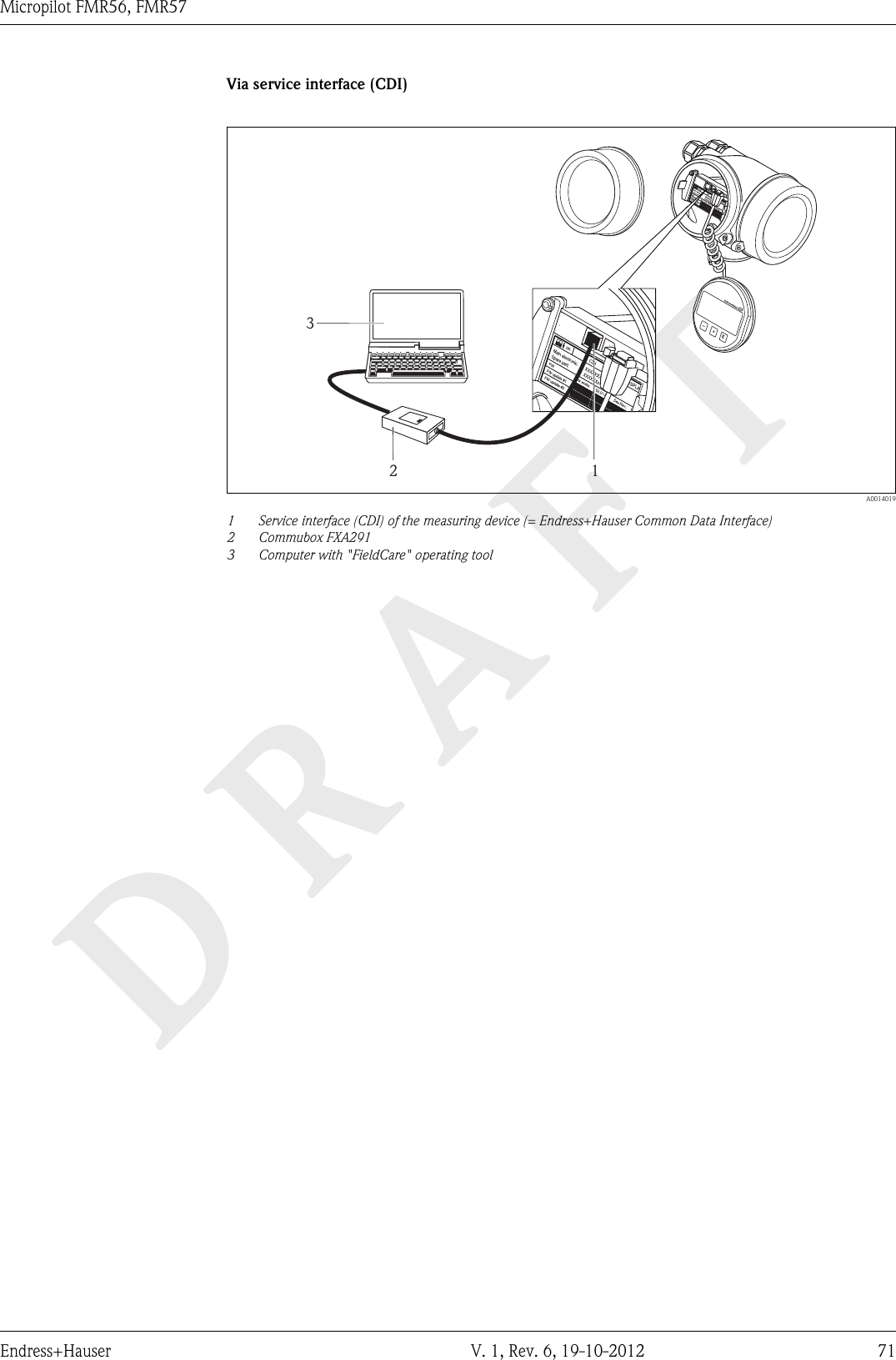
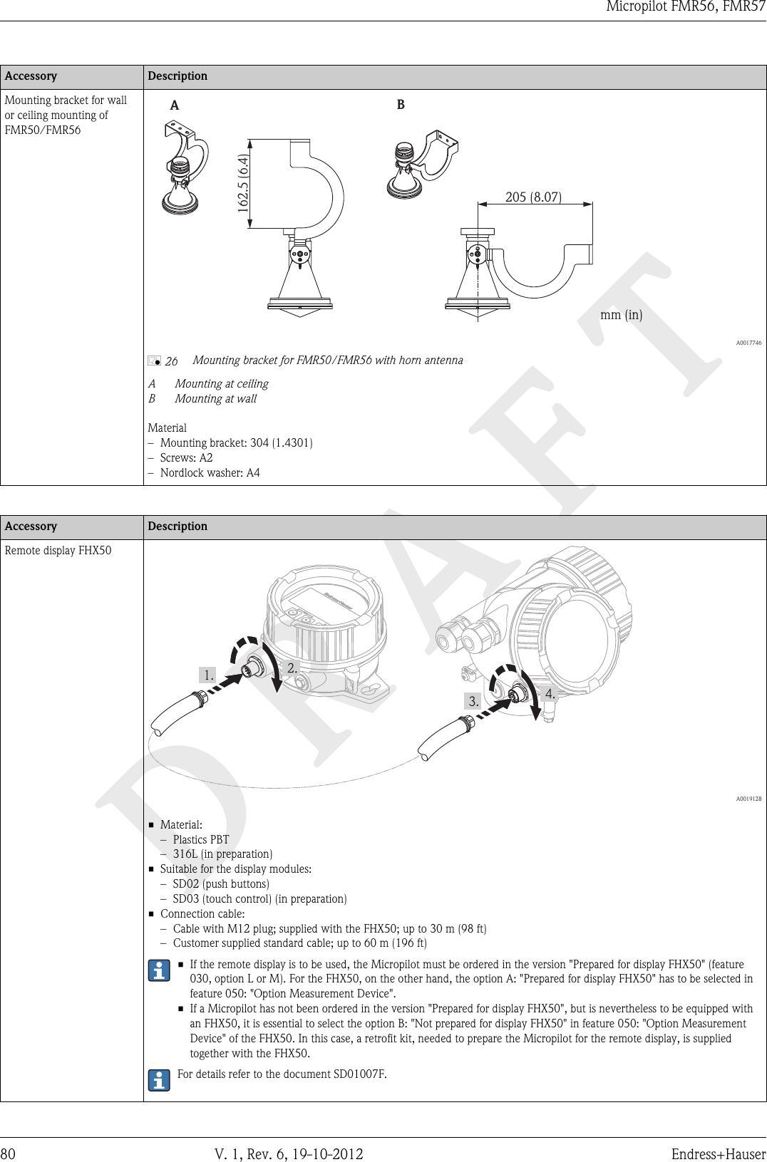
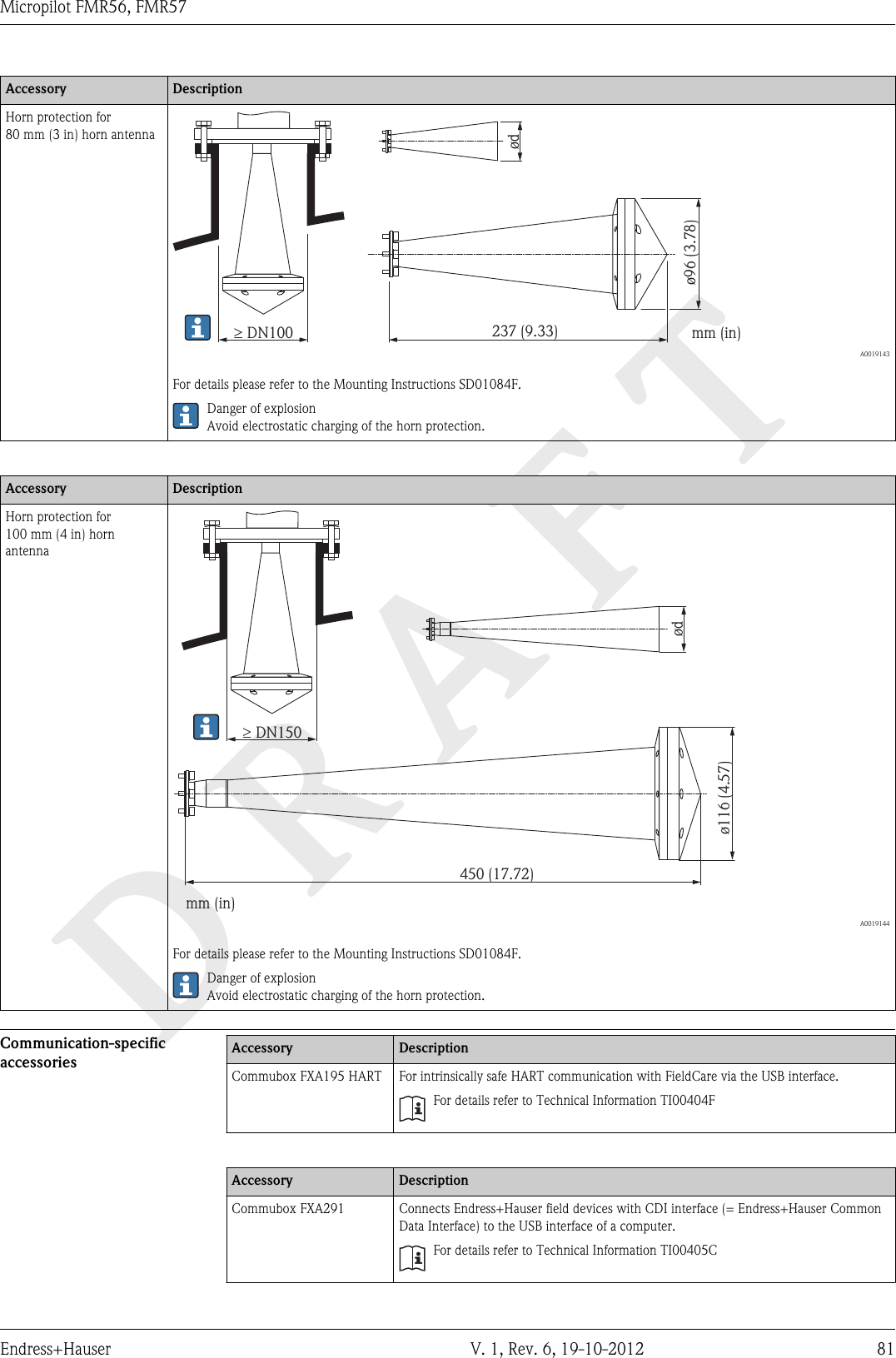
![DRAFTMicropilot FMR56, FMR5714 V. 1, Rev. 6, 19-10-2012 Endress+HauserPower supplyTerminal assignment 2-wire: 4-20mA HART+–4...20 mA4...20 mA554411228933++––1+24...20mAHART10 mmSpare part71108xxx2- wire level4-20 mA 4-20 mAHART[21]open-1+24-20mA1-channel overvoltage protection-71128617[16]A+–7B6 A0011294å 3 Terminal assignment 2-wire; 4-20mA HARTAWithout integrated overvoltage protectionB With integrated overvoltage protection1Active barrier with power supply (e.g. RN221N): Observe terminal voltage (® ä 22)2HART communication resistor (³250 W): Observe maximum load (® ä 22)3 Connection for Commubox FXA195 or FieldXpert SFX100 (via VIATOR Bluetooth modem)4Analog display device: Observe maximum load (® ä 22)5Cable screen; observe cable specification (® ä 25)6 Terminals for 4-20mA HART (passive)7 Overvoltage protection module8 Terminal for potential equalization line9 Cable entry](https://usermanual.wiki/Endress-and-Hauser-SE-KG/FMR5XKF.user-manual-III/User-Guide-2351511-Page-14.png)
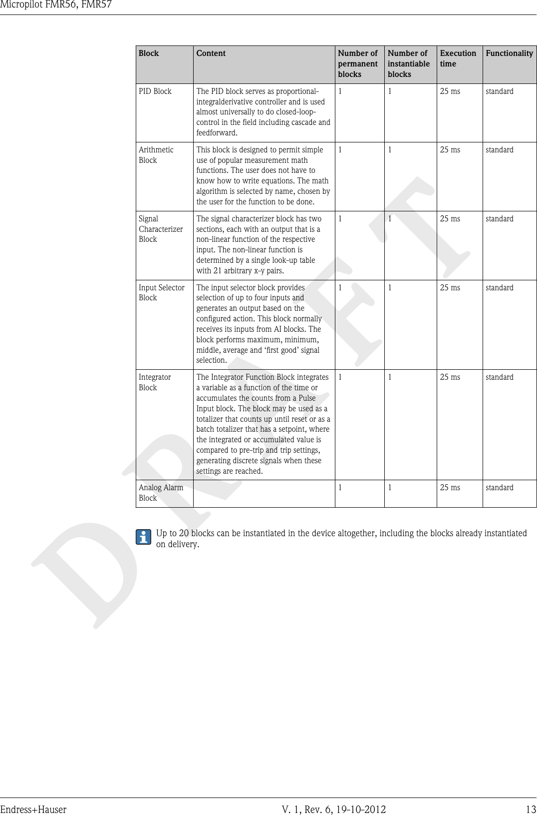
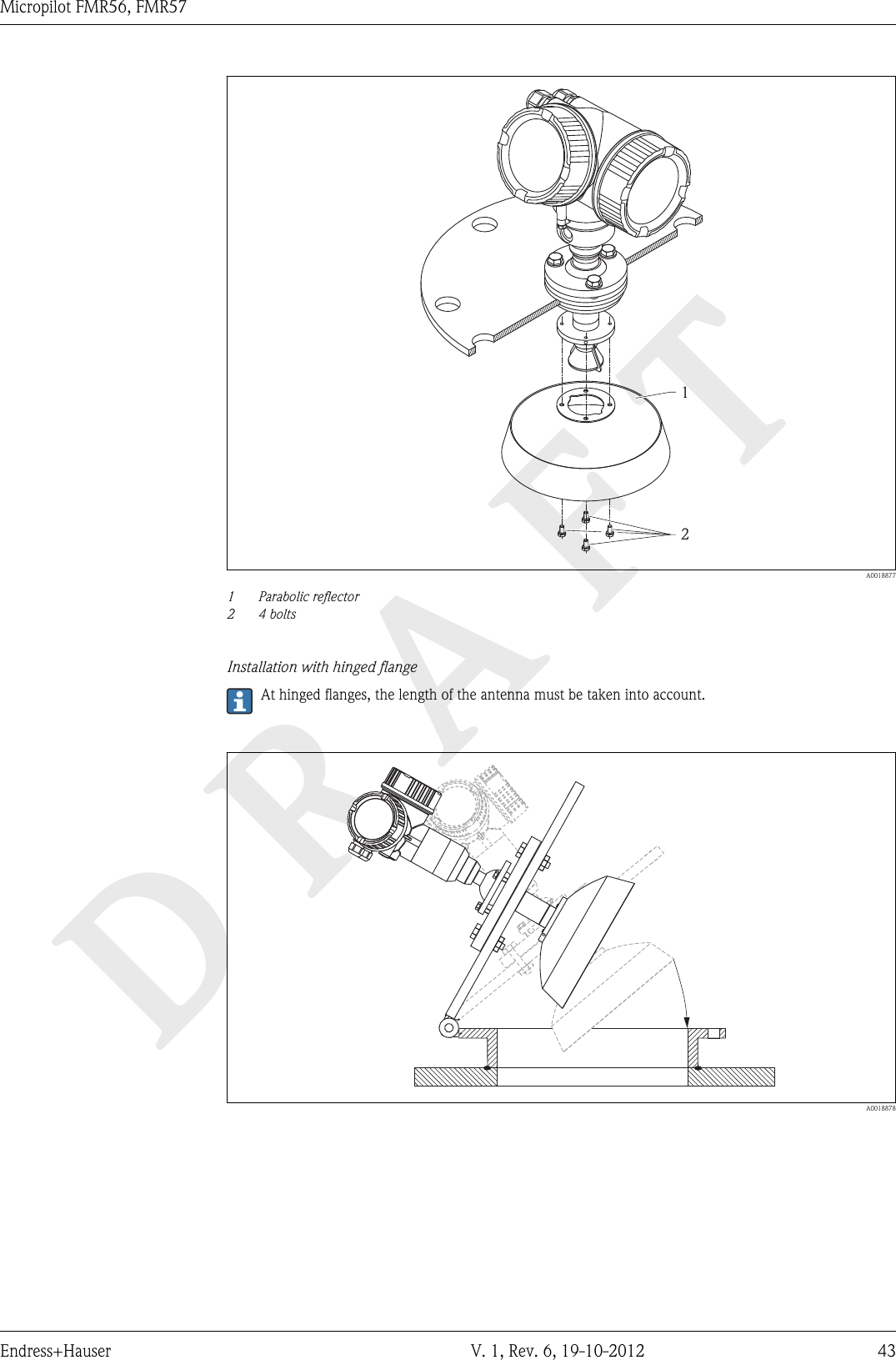
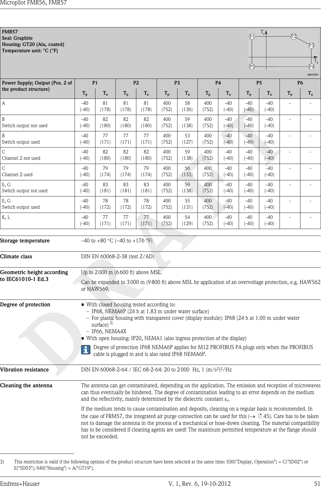
![DRAFTMicropilot FMR56, FMR57Endress+Hauser V. 1, Rev. 6, 19-10-2012 152-wire: 4-20mA HART, switch output13++244-20mA/FIELDBUS4-20mA/2-channel overvoltage protection--71128619[17]B1+24...20 mAHART10 mmSpare part71108xxx2- wire4-20 mA PFSHART[02/03]open-A1+2-3+4-1098711++--223344655114...20 mA4...20 mA³ W250³ W2503+3+4-4-++–– A0013759å 4 Terminal assignment 2-wire; 4-20mA HART, switch outputAWithout integrated overvoltage protectionB With integrated overvoltage protection1Active barrier with power supply (e.g. RN221N): Observe terminal voltage (® ä 22)2HART communication resistor (³250 W): Observe maximum load (® ä 22)3 Connection for Commubox FXA195 or FieldXpert SFX100 (via VIATOR Bluetooth modem)4Analog display device: Observe maximum load (® ä 22)5Cable screen; observe cable specification (® ä 25)6 Terminals for 4-20mA HART (passive)7 Terminals for switch output (open collector)8 Terminal for potential equalization line9 Cable entry for 4-20mA HART line10 Cable entry for switch output line11 Overvoltage protection module](https://usermanual.wiki/Endress-and-Hauser-SE-KG/FMR5XKF.user-manual-III/User-Guide-2351511-Page-15.png)
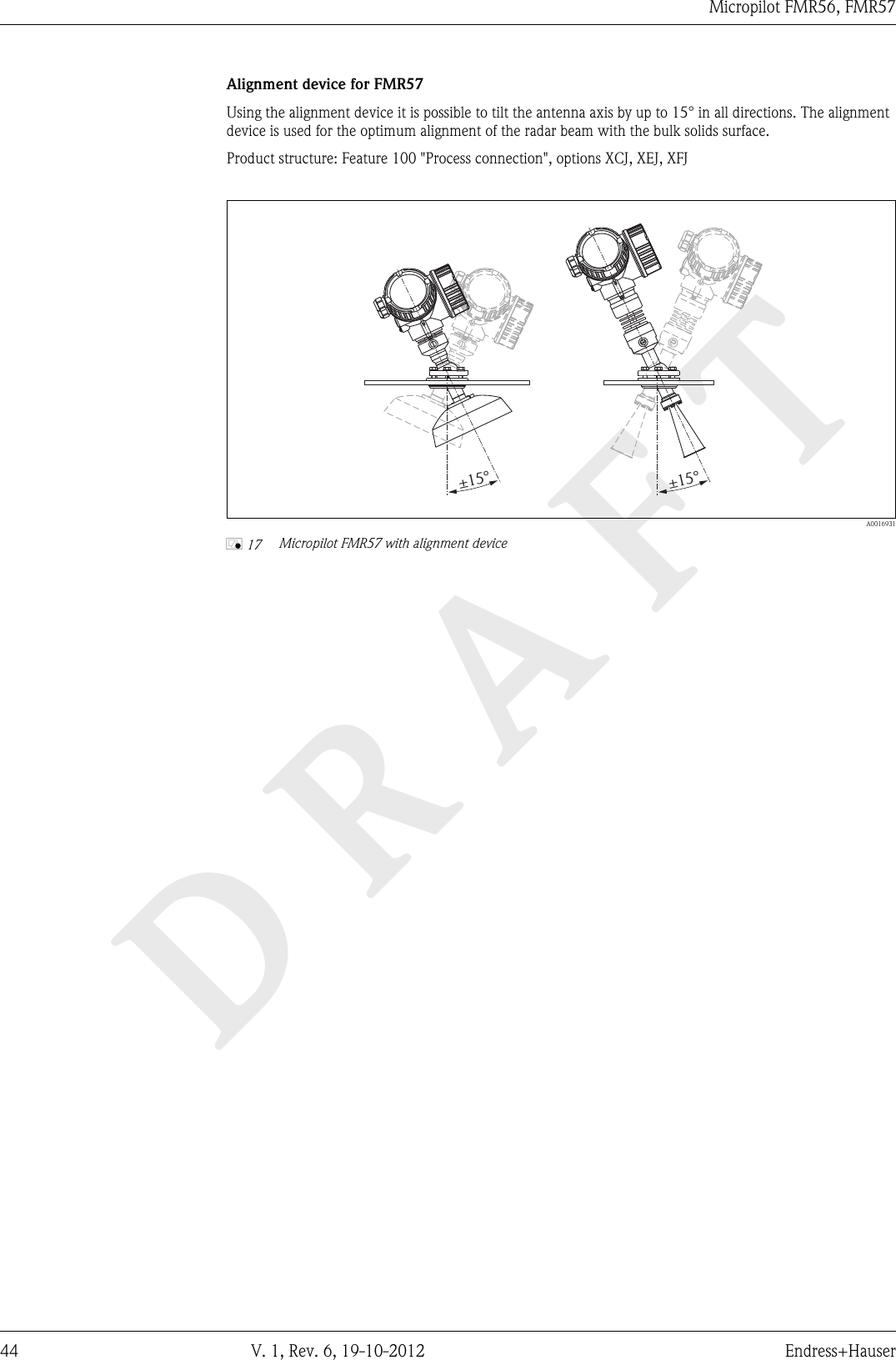
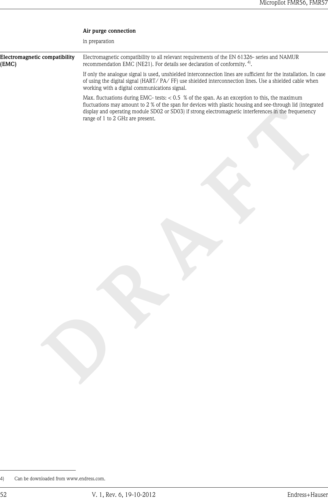
![DRAFTMicropilot FMR56, FMR5716 V. 1, Rev. 6, 19-10-2012 Endress+Hauser2-wire: 4-20mA HART, 4-20mA13++244...20mAHART4...20mA10 mmSpare part71108xxx2- wire level4-20 mA 4-20 mAHART[04/05]open--11A13++244-20mA/FIELDBUS4-20mA/2-channel overvoltage protection--71128619[17]141312+++++----112233995588667744++––++––4...20 mA4...20 mA10B4...20 mA4...20 mA A0013923å 5 Terminal assignment 2-wire, 4-20 mA HART, 4...20mAAWithout integrated overvoltage protectionB With integrated overvoltage protection1 Connection current output 22 Connection current output 13Supply voltage for current output 1 (e.g. RN221N); Observe terminal voltage (® ä 23)4Cable screen; observe cable specification (® ä 25)5HART communication resistor (³ 250 W): Observe maximum load (® ä 23)6 Connection for Commubox FXA195 or FieldXpert SFX100 (via VIATOR Bluetooth modem)7Analog display device ; observe maximum load (® ä 23)8Analog display device ; observe maximum load (® ä 23)9Supply voltage for current output 2 (e.g. RN221N); Obesrve terminal voltage (® ä 23)10 Overvoltage protection module11 Terminals for current output 212 Terminal for the potential equalization line13 Cable entry for current output 114 Cable entry for current output 2This version is also suited for single-channel operation. In this case, current output 1 (terminals 1 and2) must be used.](https://usermanual.wiki/Endress-and-Hauser-SE-KG/FMR5XKF.user-manual-III/User-Guide-2351511-Page-16.png)
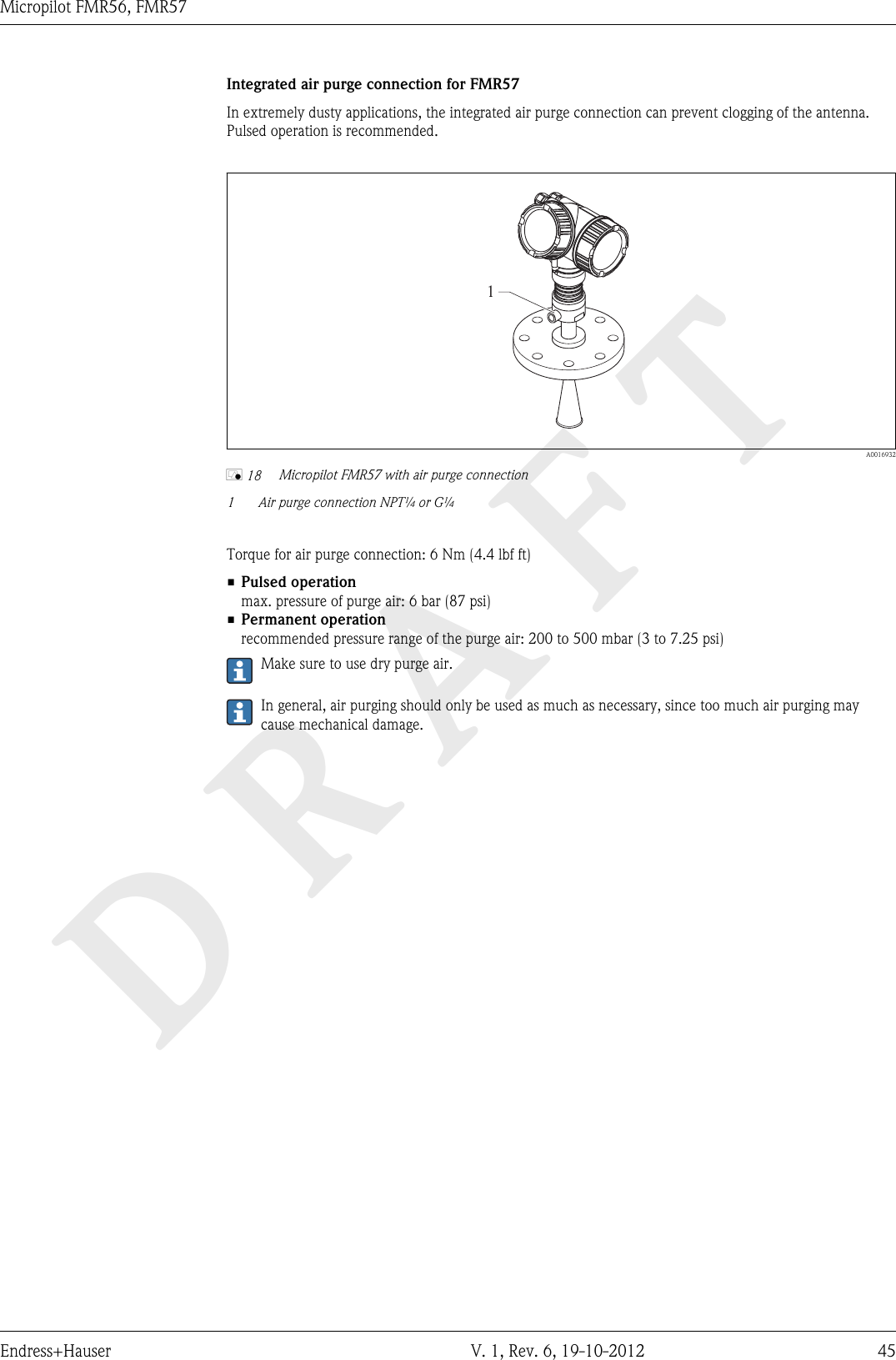
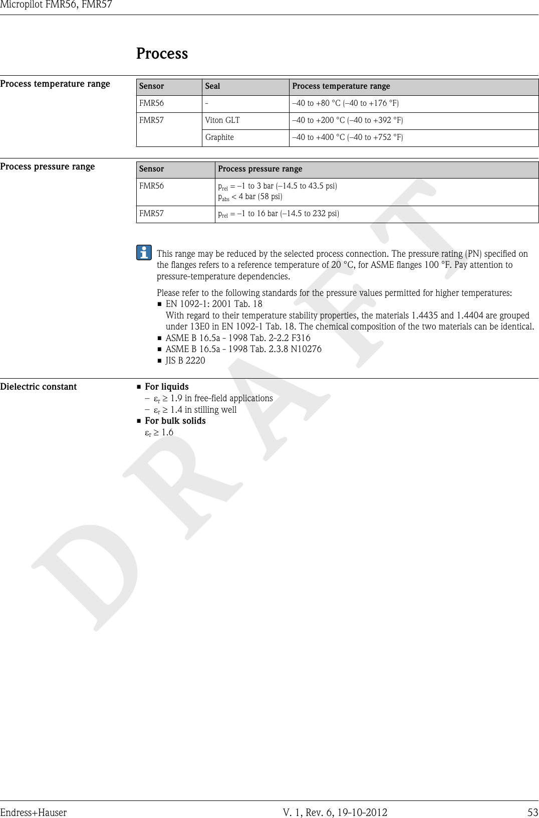
![DRAFTMicropilot FMR56, FMR57Endress+Hauser V. 1, Rev. 6, 19-10-2012 174-wire: 4-20mA HART (10.4 to 48 VDC)31+L+ 424...20 mAHART10.4...48 V=10 mmSpare part71108xxx2- wire4-20 mAHART[08]open-L-A131211910+-2 3 4678514...20 mA³ W250 A0011340å 6 Terminal assignment 4-wire; 4-20mA HART (10.4 to 48 VDC)1Evaluation unit, e.g. PLC2HART communication resistor (³250 W): Observe maximum load (® ä 24)3 Connection for Commubox FXA195 or FieldXpert SFX100 (via VIATOR Bluetooth modem)4Analog display device: Observe maximum load (® ä 24)5Signal cable including screening (if required), observe cable specification (® ä 25)6 Protective connection; do not disconnect!7Protective earth, observe cable specification (® ä 25)8 Terminals for 4...20mA HART (active)9 Terminals for supply voltage10 Supply voltage: Observe terminal voltage (® ä 24), observe cable specification (® ä 25)11 Terminal for potential equalization12 Cable entry for signal line13 Cable entry for power supply!CAUTIONTo ensure electrical safety:►Do not disconnect the protective connection (7).►Disconnect the supply voltage before disconnecting the protective earth (8).Connect protective earth to the internal ground terminal (8) before connecting the supply voltage. Ifnecessary, connect the potential matching line to the external ground terminal (12).In order to ensure electromagnetic compatibility (EMC): Do not only ground the device via theprotective earth conductor of the supply cable. Instead, the functional grounding must also beconnected to the process connection (flange or threaded connection) or to the external groundterminal.An easily accessible power switch must be installed in the proximity of the device. The power switchmust be marked as a disconnector for the device (IEC/EN61010).](https://usermanual.wiki/Endress-and-Hauser-SE-KG/FMR5XKF.user-manual-III/User-Guide-2351511-Page-17.png)
![DRAFTMicropilot FMR56, FMR5718 V. 1, Rev. 6, 19-10-2012 Endress+Hauser4-wire: 4-20mA HART (90 to 253 VAC)31+L424...20 mAHART90...253 V~10 mmSpare part71108xxx2- wire4-20 mAHART[09]open-NA131211910+-2 3 4678514...20 mA³ W250 A0018965å 7 Terminal assignment 4-wire; 4-20mA HART (90 to 253 VAC)1Evaluation unit, e.g. PLC2HART communication resistor (³250 W): Observe maximum load (® ä 24)3 Connection for Commubox FXA195 or FieldXpert SFX100 (via VIATOR Bluetooth modem)4Analog display device: Observe maximum load (® ä 24)5Signal cable including screening (if required), observe cable specification (® ä 25)6 Protective connection; do not disconnect!7Protective earth, observe cable specification (® ä 25)8 Terminals for 4...20mA HART (active)9 Terminals for supply voltage10 Supply voltage: Observe terminal voltage (® ä 24), observe cable specification (® ä 25)11 Terminal for potential equalization12 Cable entry for signal line13 Cable entry for power supply!CAUTIONTo ensure electrical safety:►Do not disconnect the protective connection (7).►Disconnect the supply voltage before disconnecting the protective earth (8).Connect protective earth to the internal ground terminal (8) before connecting the supply voltage. Ifnecessary, connect the potential matching line to the external ground terminal (12).In order to ensure electromagnetic compatibility (EMC): Do not only ground the device via theprotective earth conductor of the supply cable. Instead, the functional grounding must also beconnected to the process connection (flange or threaded connection) or to the external groundterminal.An easily accessible power switch must be installed in the proximity of the device. The power switchmust be marked as a disconnector for the device (IEC/EN61010).](https://usermanual.wiki/Endress-and-Hauser-SE-KG/FMR5XKF.user-manual-III/User-Guide-2351511-Page-18.png)
![DRAFTMicropilot FMR56, FMR57Endress+Hauser V. 1, Rev. 6, 19-10-2012 19PROFIBUS PA / FOUNDATION Fieldbus (in preparation)13++24FIELDBUS2-channel overvoltage protection--71128619[17]4-20mA/4-20mA/B11++22FIELDBUSSpare part71023457PA/FF[06/07]FIELDBUS--13++24PA/FF10 mmSpare part71108xxx2- wire level4-20 mA PFSFIELDBUS[26/27]open--A41123653+3+4-4- A0011341å 8 Terminal assignment PROFIBUS PA / FOUNDATION FieldbusAWithout integrated overvoltage protectionB With integrated overvoltage protection1Cable screen: Observe cable specifications (® ä 25)2 Terminals for switch output (open collector)3 Terminals PROFIBUS PA / FOUNDATION Fieldbus4 Terminal for potential equalization line5 Cable entries6 Overvoltage protection module](https://usermanual.wiki/Endress-and-Hauser-SE-KG/FMR5XKF.user-manual-III/User-Guide-2351511-Page-19.png)
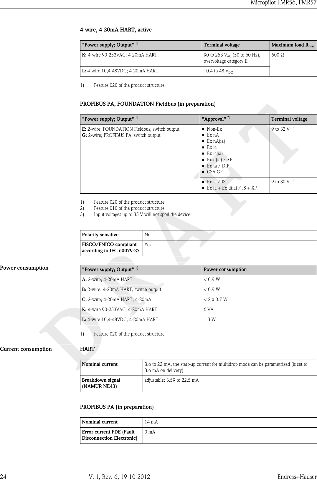
![DRAFTMicropilot FMR56, FMR5722 V. 1, Rev. 6, 19-10-2012 Endress+HauserSupply voltage An external power supply is required.Various supply units can be ordered from Endress+Hauser: see "Accessories" section (® ä 83)2-wire, 4-20mA HART, passive"Power Supply,Output" 1)"Approval" 2) Terminal voltage U atthe deviceMaximum load R, depending on the supply voltage U0 at thesupply unitA: 2-wire; 4-20mA HART • Non-Ex• Ex nA• Ex ic• CSA GP10.4 to 35 V 3)R [ ]?U0[V]1010.4 21.420 30 350500 A0017140Ex ia / IS 10.4 to 30 V 3)• Ex d(ia) / XP• Ex ic(ia)• Ex nA(ia)• Ex ta / DIP12 to 35 V 4)R [ ]WU0[V]1012 2320 30 350500 A0019136Ex ia + Ex d(ia) / IS + XP 12 to 30 V 4)1) Feature 020 of the product structure2) Feature 010 of the product structure3) For ambient temperatures Ta £ -20 °C (-4 °F) a minimum voltage of 15 V is required for the sartup of the device at the MIN error current (3,6 mA). Thestartup current can be parametrized. If the device is operated with a fixed current I ³ 5,5 mA (HART multidrop mode), a voltage of U ³ 10,4 V is sufficientthroughout the entire range of ambient temperatures.4) For ambient temperatures Ta £ -20 °C (-4 °F) a minimum voltage of 16 V is required for the satrtup of the device at the MIN error current (3.6 mA)."Power Supply, Output" 1) "Approval" 2) Terminal voltage U atthe deviceMaximum load R, depending on the supply voltage U0 at thesupply unitB: 2-wire; 4-20 mA HART,switch output• Non-Ex• Ex nA• Ex nA(ia)• Ex ic• Ex ic(ia)• Ex d(ia) / XP• Ex ta / DIP• CSA GP12 to 35 V 3)R [ ]WU0[V]1012 2320 30 350500 A0019136• Ex ia / IS• Ex ia + Ex d(ia) / IS + XP12 to 30 V 3)1) Feature 020 of the product structure2) Feature 010 of the product structure3) For ambient temperatures Ta £ -30 °C (-22 °F) a minimum voltage of 16 V is required for the satrtup of the device at the MIN error current (3.6 mA).](https://usermanual.wiki/Endress-and-Hauser-SE-KG/FMR5XKF.user-manual-III/User-Guide-2351511-Page-22.png)
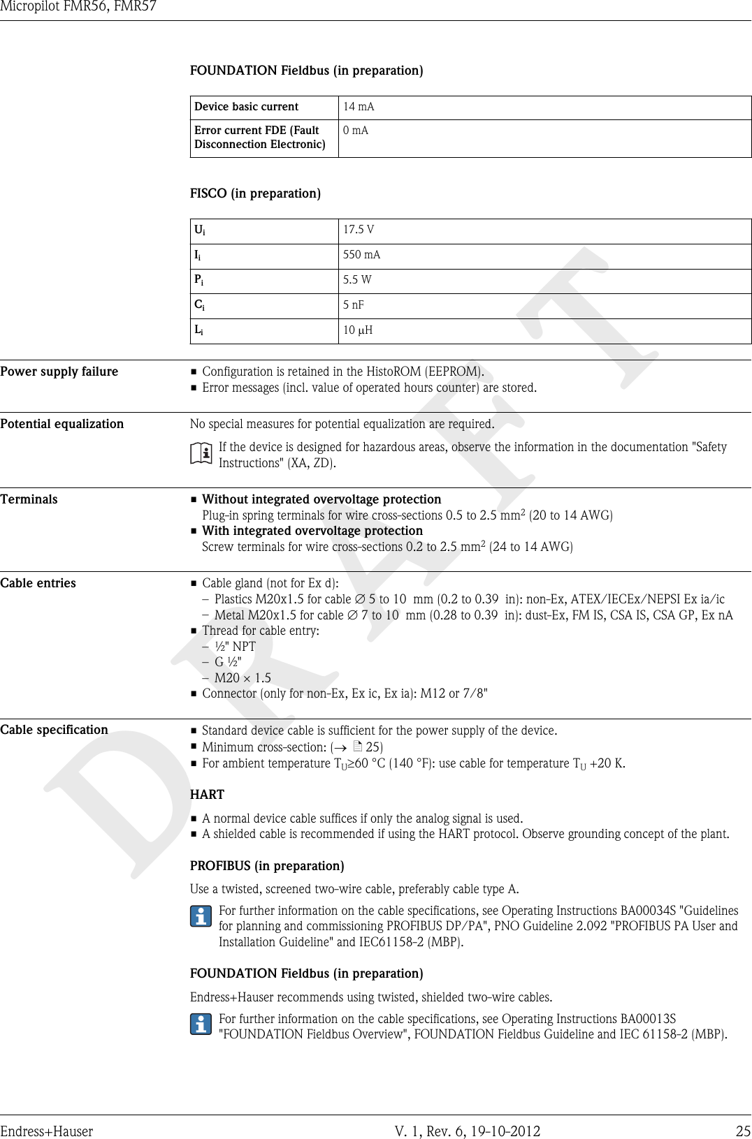
![DRAFTMicropilot FMR56, FMR57Endress+Hauser V. 1, Rev. 6, 19-10-2012 23"Power Supply, Output" 1) "Approval" 2) Terminal voltage U at thedeviceMaximum load R, depending on the supply voltage U0 at thesupply unitC: 2-wire; 4-20mA HART, 4-20mA any 12 to 30 V 3)R [ ]?U0[V]1012 2320 300500 A00170551) Feature 020 of the product structure2) Feature 010 of the product structure3) For ambient temperatures Ta £ -30 °C (-22 °F) a minimum voltage of 16 V is required for the satrtup of the device at the MIN error current (3.6 mA).Polarity reversal protection YesAdmissible residual rippleat f = 0 to 100 HzUSS < 1 VAdmissible residual rippleat f = 100 to 10000 HzUSS < 10 mV](https://usermanual.wiki/Endress-and-Hauser-SE-KG/FMR5XKF.user-manual-III/User-Guide-2351511-Page-23.png)
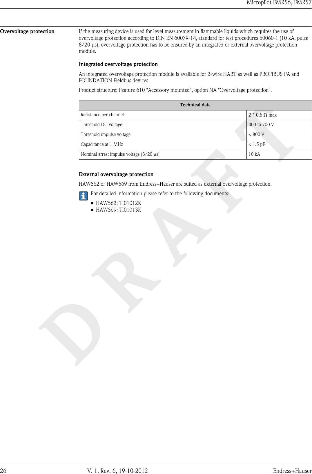
![DRAFTMicropilot FMR56, FMR57Endress+Hauser V. 1, Rev. 6, 19-10-2012 27Performance characteristicsReference operatingconditions• Temperature = +24 °C (+75 °F) ±5 °C (±9 °F)• Pressure = 960 mbar abs. (14 psia) ±100 mbar (±1.45 psi)• Humidity = 60 % ±15 %• Reflector: metal plate with a minimum diameter of 1 m (40 in)• No major interference reflections inside the signal beamMaximum measured error Typical data under reference operating conditions: DIN EN 61298-2, percentage values in relation to thespan.Device Value Outputdigital analog 1)FMR56/FMR57 Sum of non-linearity,nonrepeatability andhysteresis± 3 mm (0.12 in) ± 0.02 %Offset/Zero ± 4 mm (0.2 in) ± 0.03 %1) Add error of the analogous value to the digital value.Differing values in near-range applications3 (0.12)0-3 (-12)0 A 2 (6.6) D[m] ([ft])20 (0.79)-20 (-0.79)RD[mm] ([in]) A0019034å 11 Maximum measured error in near-range applicationsDMaximum measured errorD Distance from the reference point RA Lower edge of the antennaMeasured value resolution Dead band according to EN61298-2:• digital: 1 mm•analog: 1 mA](https://usermanual.wiki/Endress-and-Hauser-SE-KG/FMR5XKF.user-manual-III/User-Guide-2351511-Page-27.png)
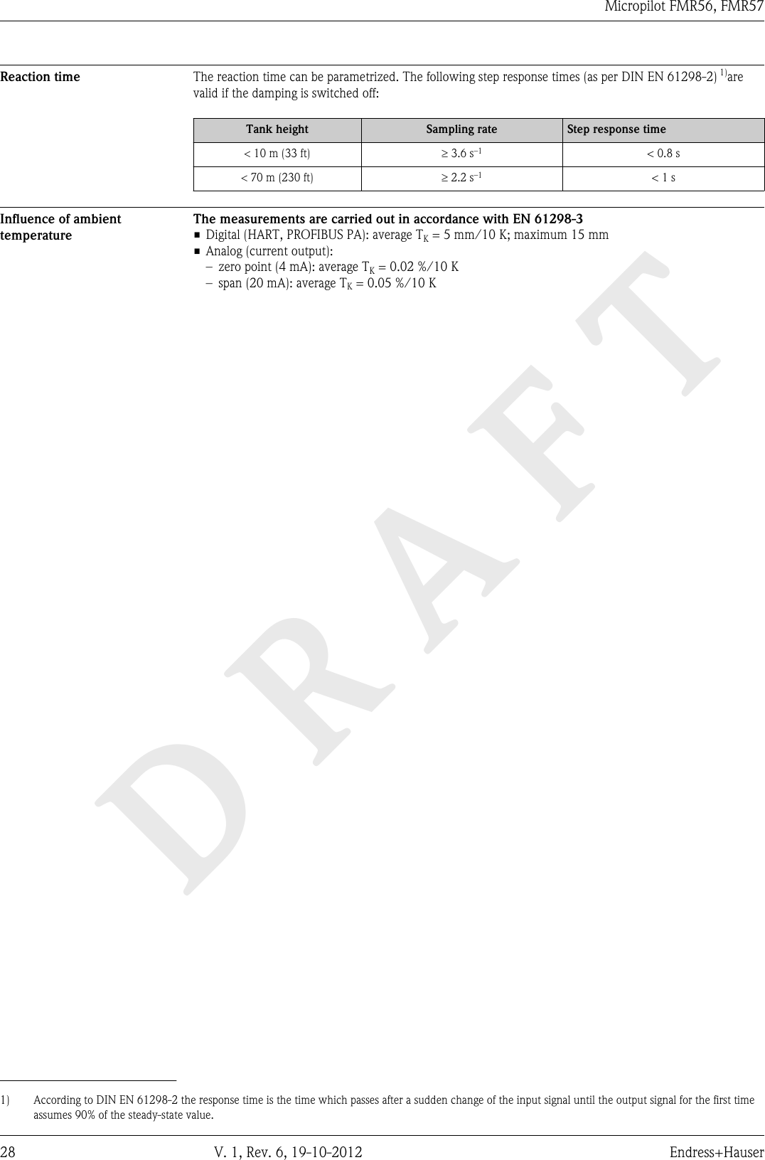
![DRAFTMicropilot FMR56, FMR5736 V. 1, Rev. 6, 19-10-2012 Endress+HauserMeasuring conditions • The measuring range begins, where the beam hits the bottom. Particularly with conical outlets the levelcannot be detected below this point. The maximum measuring range can be increased in such applicationsby using an alignment device (® ä 44).•In case of media with a low dielectric constant (er = 1.5 to 2.5) 2), the bottom can be visible through themedium at low levels. In order to guarantee the required accuracy in these cases, it is recommended toposition the zero-point at a distance C above the bottom (see figure).• In principle it is possible to measure up to the tip of the antenna with Micropilot. However, due toconsiderations regarding abrasion and build-up and depending on the orientation of the product surface(angle of repose), the end of the measuring range should be at a distance of A (see figure) from the tip ofthe antenna. If required, and if some conditions (high DC value, flat angle of repose) are met, shorterdistances can be achieved.100%0%ABC A0016916Device A [mm (in)] C [mm (in)]FMR56 400(15.7) 50 to 150(1.97 to 5.91)FMR572) Dielectric constants of important media commonly used in the industry are summarized in the document SD106F, which can be downloaded from theEndress+Hauser web page (www.endress.com).](https://usermanual.wiki/Endress-and-Hauser-SE-KG/FMR5XKF.user-manual-III/User-Guide-2351511-Page-36.png)

![DRAFTMicropilot FMR56, FMR5774 V. 1, Rev. 6, 19-10-2012 Endress+Hauserdistance of 4 to 40 km from the stations mentioned, the maximum mounting height is restricted to15 m (49 ft).Astronomical stationsCountry Name of the station Geographical latitude Geographical longitudeGermany Effelsberg 50°31'32" N 06°53'00" EFinland Metsähovi 60°13'04" N 24°23'37" ETuorla 60°24'56" N 24°26'31" EFrance Plateau de Bure 44°38'01" N 05°54'26" EFloirac 44°50'10" N 00°31'37" WUnited Kingdom Cambridge 52°09'59" N 00°02'20" EDamhall 53°09'22" N 02°32'03" WJodrell Bank 53°14'10" N 02°18'26" WKnockin 52°47'24" N 02°59'45" WPickmere 53°17'18" N 02°26'38" WItaly Medicina 44°31'14" N 11°38'49" ENoto 36°52'34" N 14°59'21" ESardinia 39°29'50" N 09°14'40" EPoland Krakow Fort Skala 50°03'18" N 19°49'36" ERussia Dmitrov 56°26'00" N 37°27'00" EKalyazin 57°13'22" N 37°54'01" EPushchino 54°49'00" N 37°40'00" EZelenchukskaya 43°49'53" N 41°35'32" ESweden Onsala 57°23'45" N 11°55'35" ESwitzerland Bleien 47°20'26" N 08°06'44" ESpain Yebes 40°31'27" N 03°05'22" WRobledo 40°25'38" N 04°14'57" WHungary Penc 47°47'22" N 19°16'53" EIn general the requirements of EN 302729-1/2 has to be taken in consideration.Radio standardEN302372-1/2The devices Micropilot FMR50, FMR51, FMR52, FMR53, FMR54, FMR56 and FMR57 are conform withthe TLPR (Tanks Level Probing Radar) standard EN302372-1/2 and can always be used in closed tanks orbins. For installation, points a to f in Annex B of EN302372-1 have to be taken into account.FCC / Industry Canada This device complies with Part 15 of the FCC rules. Operation is subject to the following two conditions: (1)This device may not cause harmful interference, and (2) this device must accept any interference received,including interference that may cause undesired operation.Canada CNR-Gen Section 7.1.3This device complies with Industry Canada licence-exempt RSS standard(s). Operation is subject to thefollowing two conditions: (1) This device may not interference, and (2) this device must accept anyinterference, including interference that may cause undesired operation of the device.Le présent appareil est conforme aux CNR d'Industrie Canada applicables aux appareils radio exempts delicence. L'exploitation est autorisée aux deux conditions suivantes : (1) l'appareil ne doit pas produire debrouillage, et (2) l'utilisateur de l'appareil doit accepter tout brouillage radioélectrique subi, même si lebrouillage est susceptible d'en compromettre le fonctionnement.[Any] changes or modifications not expressly approved by the party responsible for compliance could void theuser's authority to operate the equipment.](https://usermanual.wiki/Endress-and-Hauser-SE-KG/FMR5XKF.user-manual-III/User-Guide-2351511-Page-74.png)
![DRAFTMicropilot FMR56, FMR5784 V. 1, Rev. 6, 19-10-2012 Endress+HauserDocumentationThe following document types are available:• On the CD supplied with the device•In the Download Area of the Endress+Hauser Internet site: www.endress.com ® DownloadStandard documentation Micropilot FMR56, FMR57Correlation of documentations to the device:Device Power supply,outputCommunikation Document type Document codeFMP56,FMP57A, B, C, K, L HART Operating Instructions BA01048F/00/ENBrief Operating Instructions KA01102F/00/ENDescription of Device Parameters GP01014F/00/ENG PROFIBUS PA(in preparation)Operating Instructions BA01127F/00/ENBrief Operating Instructions KA01131F/00/ENDescription of Device Parameters GP01018F/00/ENE FOUNDATION Fieldbus(in preparation)Operating Instructions BA01123F/00/ENBrief Operating Instructions KA01127F/00/ENDescription of Device Parameters GP01017F/00/ENSupplementarydocumentationDevice Document type Document codeFieldgate FXA520 Technical Information TI369F/00/ENTank Side Monitor NRF590 Technical Information TI402F/00/ENOperating Instructions BA256F/00/ENDescription of Device Parameters BA257F/00/ENSafety Instructions (XA) Depending on the approval, the following Safety Instructions (XA) are supplied with the device. They are anintegral part of the Operating Instructions.Feature 010 Approval Available for Safety Instructions HART Safety InstructionsPROFIBUSFOUNDATION FieldbusBA ATEX: II 1 G Ex ia IIC T6 Ga • FMR56• FMR57 XA00677F XA00685FBB ATEX: II 1/2 G Ex ia IIC T6-T1 Ga/Gb • FMR56• FMR57 XA00677F XA00685FBC ATEX: II 1/2 G Ex d [ia] IIC T6-T1 Ga/Gb • FMR56• FMR57XA00680F XA00688FBD ATEX: II 1/2/3 G Ex ic [ia Ga] IIC T6-T1 Ga/Gb/Gc FMR57 XA00678F XA00686FBE ATEX: II 1 D Ex ta IIIC T500 xx°C Da • FMR56• FMR57XA00682F XA00690FBF ATEX: II 1/2 D Ex ta IIIC Txx°C Da/Db • FMR56• FMR57XA00682F XA00690FBG ATEX: II 3 G Ex nA IIC T6-T1 Gc • FMR56• FMR57 XA00679F XA00687FBH ATEX: II 3 G Ex ic IIC T6-T1 Gc • FMR56• FMR57 XA00679F XA00687FBL ATEX: II 1/2/3 G Ex nA [ia Ga] IIC T6-T1 Ga/Gb/Gc FMR57 XA00678F XA00686FB2 ATEX: II 1/2 G Ex ia IIC T6-T1 Ga/GbATEX: II 1/2 D Ex ia IIIC Txx°C Da/Db• FMR56• FMR57XA00683F XA00691F](https://usermanual.wiki/Endress-and-Hauser-SE-KG/FMR5XKF.user-manual-III/User-Guide-2351511-Page-84.png)
![DRAFTMicropilot FMR56, FMR57Endress+Hauser V. 1, Rev. 6, 19-10-2012 85Feature 010 Approval Available for Safety Instructions HART Safety InstructionsPROFIBUSFOUNDATION FieldbusB3 ATEX: II 1/2 G Ex d [ia] IIC T6-T1 Ga/GbATEX: II 1/2 D Ex ta IIIC Txx°C Da/Db• FMR56• FMR57XA00684F XA00692FIA IECEx: Ex ia IIC T6-T1 Ga • FMR56• FMR57 XA00677F XA00685FIB IECEx: Ex ia IIC T6-T1 Ga/Gb • FMR56• FMR57 XA00677F XA00685FIC IECEx: Ex d [ia] IIC T6-T1 Ga/Gb • FMR56• FMR57XA00680F XA00688FID IECEx: Ex ic [ia Ga] IIC T6-T1 Ga/Gb/Gc FMR57 XA00678F XA00686FIE IECEx: Ex ta IIIC T500 xx°C Da • FMR56• FMR57XA00682F XA00690FIF IECEx: Ex ta IIIC Txx°C Da/Db • FMR56• FMR57XA00682F XA00690FIG IECEx: Ex nA IIC T6-T1 Gc • FMR56• FMR57 XA00679F XA00687FIH IECEx: Ex ic IIC T6-T1 Gc • FMR56• FMR57 XA00679F XA00687FIL IECEx: Ex nA [ia Ga] IIC T6-T1 Ga/Gb/Gc FMR57 XA00678F XA00686FI2 IECEx: Ex ia IIC T6-T1 Ga/GbIECEx: Ex ia IIIC Txx°C Da/Db• FMR56• FMR57XA00683F XA00691FI3 IECEx: Ex d [ia] IIC T6-T1 Ga/GbIEXEx: Ex ta IIIC Txx°C Da/Db• FMR56• FMR57XA00684F XA00692FFor certified devices the relevant Safety Instructions (XA) are indicated on the nameplate.If the device is prepared for the remote display FHX50 (product structure: feature 030: Display, Operation",option L or M), the Ex marking of some certificates changes according to the following table 6):Feature 010 ("Approval") Feature 030 ("Display, Operation") Ex markingBE L oder M ATEX II 1D Ex ta [ia] IIIC T500 xx°C DaBF L oder M ATEX II 1/2 D Ex ta [ia Db] IIIC Txx°C Da/DbBG L oder M ATEX II 3G Ex nA [ia Ga] IIC T6 GcBH L oder M ATEX II 3G Ex ic [ia Ga] IIC T6 GcB3 L oder M ATEX II 1/2G Ex d [ia] IIC T6 Ga/Gb,ATEX II 1/2D Ex ta [ia Db] IIIC Txx°C Da/DbIE L oder M IECEx Ex ta [ia] IIIC T500 xx°C DaIF L oder M IECEx ta [ia Db] IIIC Txx°C Da/DbIG L oder M IECEx Ex nA [ia Ga] IIC T6 GcIH L oder M IECEx Ex ic [ia Ga] IIC T6 GcI3 L oder M IECEx Ex d [ia] IIC T6 Ga/Gb,IECEx Ex ta [ia Db] IIIC Txx°C Da/Db6) The marking of certificates not mentioned in this table are not affected by the FHX50.](https://usermanual.wiki/Endress-and-Hauser-SE-KG/FMR5XKF.user-manual-III/User-Guide-2351511-Page-85.png)