Endress and Hauser and Co FMR09 Level Probing Radar User Manual Micropilot S FMR540
Endress and Hauser GmbH and Co Level Probing Radar Micropilot S FMR540
USer Manual
TI412F/00/en/09.06
Technical Information
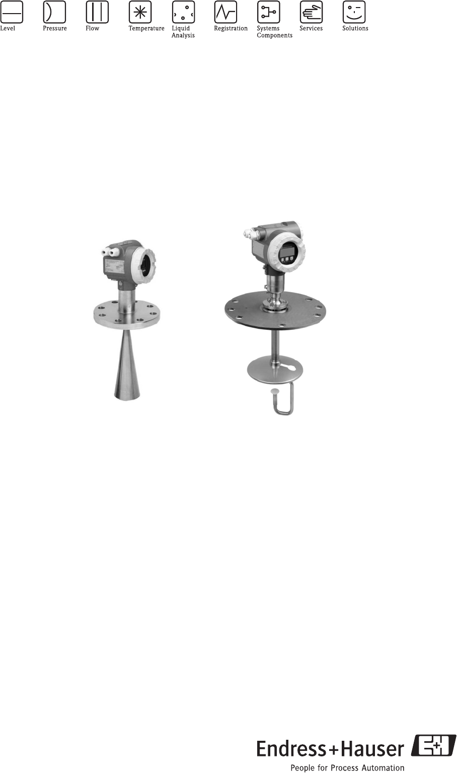
Micropilot S FMR540
Level-Radar
Smart Transmitter for continuous and non-contact precision level
measurement. For custody transfer and inventory control
applications with NMi and PTB approvals.
Application
The Micropilot S is used for highly accurate level
measurement in storage tanks and can be applied in
custody transfer applications. It meets the relevant
requirements according to OIML R85 and API 3.1B.
Typical areas of application are:
• The with parabolic antenna is excellently suited for
free space applications up to 40 m (131 ft).
• The with horn antenna is suitable for free space
applications that disallow the use of a parabolic
antenna due to tank/nozzle geometry.
The FMR540 with DN200 (8") parabolic antenna offers
high beam focussing of 4° and is therefore ideally suited
to applications with nozzles situated close to the tank
wall.
The FMR540 with DN100 (4") horn antenna is designed
for all small nozzles sizes.
Your benefits
• Better than 1 mm accuracy.
• National approvals (NMi, PTB) for custody transfer.
• Applicable as stand-alone system or tied into tank
gauging systems via the Tank Side Monitor NRF590.
• Cost-effective and simple installation via 4-wire cable
with HART and 24V DC intrinsically safe power
supply.
• low cost, low weight UNIversal flanges
• top target positioners to compensate any flange
inclination
• easy on-site operation via menu-driven alphanumeric
display
• easy commissioning, documentation and diagnostics
via operating software (ToF Tool - Fieldtool Package or
FieldCare)
• HART communication.

Micropilot S FMR540
2Endress+Hauser
Table of contents
Function and system design. . . . . . . . . . . . . . . . . . . . . 3
Measuring principle . . . . . . . . . . . . . . . . . . . . . . . . . . . . . . . . . . . 3
Equipment architecture . . . . . . . . . . . . . . . . . . . . . . . . . . . . . . . . 4
Custody transfer applications . . . . . . . . . . . . . . . . . . . . . . . . . . . . 5
Integrated in tank gauging system . . . . . . . . . . . . . . . . . . . . . . . . . 6
Input . . . . . . . . . . . . . . . . . . . . . . . . . . . . . . . . . . . . . . 7
Measured variable . . . . . . . . . . . . . . . . . . . . . . . . . . . . . . . . . . . . 7
Antenna selection for Micropilot S-series . . . . . . . . . . . . . . . . . . . 7
Measuring range . . . . . . . . . . . . . . . . . . . . . . . . . . . . . . . . . . . . . . 8
Measuring range depending on sensor type and media group . . . . . 8
Measuring conditions . . . . . . . . . . . . . . . . . . . . . . . . . . . . . . . . . . 9
Operating frequency . . . . . . . . . . . . . . . . . . . . . . . . . . . . . . . . . . . 9
Output . . . . . . . . . . . . . . . . . . . . . . . . . . . . . . . . . . . . 10
Output signal . . . . . . . . . . . . . . . . . . . . . . . . . . . . . . . . . . . . . . . 10
Signal on alarm . . . . . . . . . . . . . . . . . . . . . . . . . . . . . . . . . . . . . 10
Linearization . . . . . . . . . . . . . . . . . . . . . . . . . . . . . . . . . . . . . . . 10
Galvanic isolation . . . . . . . . . . . . . . . . . . . . . . . . . . . . . . . . . . . . 10
Auxiliary energy . . . . . . . . . . . . . . . . . . . . . . . . . . . . 10
Electrical connection . . . . . . . . . . . . . . . . . . . . . . . . . . . . . . . . . 10
Terminal assignment 4…20 mA with HART . . . . . . . . . . . . . . . . 11
Load HART . . . . . . . . . . . . . . . . . . . . . . . . . . . . . . . . . . . . . . . . 12
Cable entry . . . . . . . . . . . . . . . . . . . . . . . . . . . . . . . . . . . . . . . . 12
Supply voltage . . . . . . . . . . . . . . . . . . . . . . . . . . . . . . . . . . . . . . 12
Power consumption . . . . . . . . . . . . . . . . . . . . . . . . . . . . . . . . . . 12
Current consumption . . . . . . . . . . . . . . . . . . . . . . . . . . . . . . . . . 12
Residual ripple HART . . . . . . . . . . . . . . . . . . . . . . . . . . . . . . . . . 12
Max noise HART . . . . . . . . . . . . . . . . . . . . . . . . . . . . . . . . . . . . 12
Power supply . . . . . . . . . . . . . . . . . . . . . . . . . . . . . . . . . . . . . . . 12
mm accuracy . . . . . . . . . . . . . . . . . . . . . . . . . . . . . . . . . . . . . . . 12
Overvoltage protector . . . . . . . . . . . . . . . . . . . . . . . . . . . . . . . . . 12
Performance characteristics. . . . . . . . . . . . . . . . . . . . 13
Note . . . . . . . . . . . . . . . . . . . . . . . . . . . . . . . . . . . . . . . . . . . . . 13
Reference operating conditions . . . . . . . . . . . . . . . . . . . . . . . . . . 13
Maximum measured error . . . . . . . . . . . . . . . . . . . . . . . . . . . . . 13
Software reliability . . . . . . . . . . . . . . . . . . . . . . . . . . . . . . . . . . . 13
Hysteresis . . . . . . . . . . . . . . . . . . . . . . . . . . . . . . . . . . . . . . . . . . 13
Long-term drift . . . . . . . . . . . . . . . . . . . . . . . . . . . . . . . . . . . . . . 13
Influence of ambiente temperature . . . . . . . . . . . . . . . . . . . . . . . 13
Proof of accuracy of custody transfer versions . . . . . . . . . . . . . . . 13
Non-repeatability . . . . . . . . . . . . . . . . . . . . . . . . . . . . . . . . . . . . 13
Resolution . . . . . . . . . . . . . . . . . . . . . . . . . . . . . . . . . . . . . . . . . 13
Inventory control versions . . . . . . . . . . . . . . . . . . . . . . . . . . . . . 13
Operating conditions: Installation . . . . . . . . . . . . . . . 14
Installation instructions . . . . . . . . . . . . . . . . . . . . . . . . . . . . . . . . 14
Beam angle . . . . . . . . . . . . . . . . . . . . . . . . . . . . . . . . . . . . . . . . 15
Installation on tank FMR540 . . . . . . . . . . . . . . . . . . . . . . . . . . . 16
FMR540 with top target positioner . . . . . . . . . . . . . . . . . . . . . . . 18
Integrated air purge connection . . . . . . . . . . . . . . . . . . . . . . . . . 18
Operating conditions: Environment. . . . . . . . . . . . . . 19
Ambient temperature range . . . . . . . . . . . . . . . . . . . . . . . . . . . . 19
Storage temperature . . . . . . . . . . . . . . . . . . . . . . . . . . . . . . . . . . 19
Climate class . . . . . . . . . . . . . . . . . . . . . . . . . . . . . . . . . . . . . . . 19
Degree of protection . . . . . . . . . . . . . . . . . . . . . . . . . . . . . . . . . 19
Vibration resistance . . . . . . . . . . . . . . . . . . . . . . . . . . . . . . . . . . 19
Cleaning of the antenna . . . . . . . . . . . . . . . . . . . . . . . . . . . . . . . 19
Electromagnetic compatibility . . . . . . . . . . . . . . . . . . . . . . . . . . 19
Approvals for custody transfer applications . . . . . . . . . . . . . . . . . 19
Operating conditions: Process . . . . . . . . . . . . . . . . . . 19
Process temperature range . . . . . . . . . . . . . . . . . . . . . . . . . . . . . 19
Process pressure limits . . . . . . . . . . . . . . . . . . . . . . . . . . . . . . . . 19
Antenna core . . . . . . . . . . . . . . . . . . . . . . . . . . . . . . . . . . . . . . . 19
Wetted parts . . . . . . . . . . . . . . . . . . . . . . . . . . . . . . . . . . . . . . . 19
Optional (top target positioner) . . . . . . . . . . . . . . . . . . . . . . . . . . 19
Mechanical construction . . . . . . . . . . . . . . . . . . . . . . 20
Design, dimensions . . . . . . . . . . . . . . . . . . . . . . . . . . . . . . . . . . 20
Type plate / type plate for custody transfer applications . . . . . . . 22
Endress+Hauser UNI flange . . . . . . . . . . . . . . . . . . . . . . . . . . . . 23
Weight . . . . . . . . . . . . . . . . . . . . . . . . . . . . . . . . . . . . . . . . . . . 24
Material . . . . . . . . . . . . . . . . . . . . . . . . . . . . . . . . . . . . . . . . . . . 24
Human interface . . . . . . . . . . . . . . . . . . . . . . . . . . . . 25
Operation concept . . . . . . . . . . . . . . . . . . . . . . . . . . . . . . . . . . . 25
Display elements . . . . . . . . . . . . . . . . . . . . . . . . . . . . . . . . . . . . 25
Operating elements . . . . . . . . . . . . . . . . . . . . . . . . . . . . . . . . . . 26
On-site configuration . . . . . . . . . . . . . . . . . . . . . . . . . . . . . . . . . 27
Remote configuration . . . . . . . . . . . . . . . . . . . . . . . . . . . . . . . . . 28
Certificates and approvals . . . . . . . . . . . . . . . . . . . . . 29
CE approval . . . . . . . . . . . . . . . . . . . . . . . . . . . . . . . . . . . . . . . . 29
Ex approval . . . . . . . . . . . . . . . . . . . . . . . . . . . . . . . . . . . . . . . . 29
External standards and guidelines . . . . . . . . . . . . . . . . . . . . . . . . 29
Type approvals for custody transfer approvals . . . . . . . . . . . . . . . 29
RF approvals . . . . . . . . . . . . . . . . . . . . . . . . . . . . . . . . . . . . . . . 29
Ordering information. . . . . . . . . . . . . . . . . . . . . . . . . 30
Micropilot S FMR540 . . . . . . . . . . . . . . . . . . . . . . . . . . . . . . . . 30
Ordering structure (continued) . . . . . . . . . . . . . . . . . . . . . . . 31
Accessories . . . . . . . . . . . . . . . . . . . . . . . . . . . . . . . . 32
Weather protection cover . . . . . . . . . . . . . . . . . . . . . . . . . . . . . . 32
Sensor alignment tool for Target Positioner (alignment device option)
only . . . . . . . . . . . . . . . . . . . . . . . . . . . . . . . . . . . . . . . . . . . . . . 32
Commubox FXA191 HART . . . . . . . . . . . . . . . . . . . . . . . . . . . . 32
Commubox FXA195 HART . . . . . . . . . . . . . . . . . . . . . . . . . . . . 32
Commubox FXA291 . . . . . . . . . . . . . . . . . . . . . . . . . . . . . . . . . 33
ToF Adapter FXA291 . . . . . . . . . . . . . . . . . . . . . . . . . . . . . . . . . 33
Documentation . . . . . . . . . . . . . . . . . . . . . . . . . . . . . 34
Fields of activities . . . . . . . . . . . . . . . . . . . . . . . . . . . . . . . . . . . . 34
Technical Information . . . . . . . . . . . . . . . . . . . . . . . . . . . . . . . . 34
Operating Instructions . . . . . . . . . . . . . . . . . . . . . . . . . . . . . . . . 34
Certificates . . . . . . . . . . . . . . . . . . . . . . . . . . . . . . . . . . . . . . . . 34
Patents . . . . . . . . . . . . . . . . . . . . . . . . . . . . . . . . . . . . 35
. . . . . . . . . . . . . . . . . . . . . . . . . . . . . . . . . . . . . . . . . . . . . . . . . 35
Micropilot S FMR540
Endress+Hauser 3
Function and system design
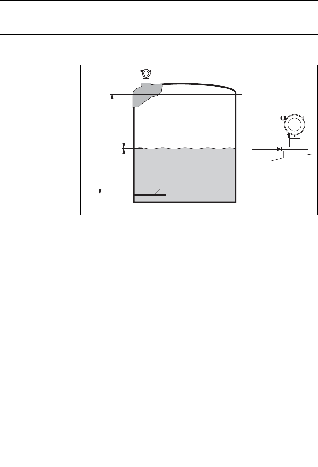
Measuring principle The Micropilot is a "downward-looking" measuring system, operating based on the time-of-flight method. It
measures the distance from the reference point (process connection) to the product surface. Radar impulses are
emitted by an antenna, reflected off the product surface and received again by the radar system.
L00-FMR250xx-15-00-00-en-001
Input
The reflected radar impulses are received by the antenna and transmitted into the electronics. A microprocessor
evaluates the signal and identifies the level echo caused by the reflection of the radar impulse at the product
surface. The unambiguous signal identification is accomplished by the PulseMaster® software, based on many
years of experience with time-of-flight technology.
The distance D to the product surface is proportional to the time of flight t of the impulse:
D = c · t/2,
with c being the speed of light.
Based on the known empty distance E, the level L is calculated:
L = E – D
Reference point for "E" is the lower surface of the process connection. For highly precise level measurements,
it is of crucial importance to have a stable mounting position (GRH) of the radar gauge or to compensate for
the effects of tank movements during filling and emptying cycles. This can be done by either using the dip table
integrated in the Micropilot S FMR53x / 540 or by using the compensation methods integrated into the Tank
Side Monitor NRF590.
The Micropilot is equipped with functions to suppress interference echoes. The user can activate these
functions. They ensure that interference echoes (e.g. from edges and weld seames) are not interpreted as level
echo.
Output
The Micropilot is commissioned by entering an empty distance E (=zero), a full distance F (=span) and an
application parameter. The application parameter automatically adapts the instrument to the measuring
conditions. The data points “E” and “F” correspond with 4mA and 20mA for instruments with current output.
They correspond with 0 % and 100 % for digital outputs and the display module. For inventory control or
custody transfer applications, the measurement should always be transferred via digital communication
(HART).
A linearization with max. 32 points, based on a table entered either manually or semi-automatically, can be
activated locally or remotely. This function provides a measurement in engineering units and a linear output
signal for spheres, horizontal cylindrical tanks and tanks with conical outlet.
20 mA
100%
4mA
0%
D
L
F
E
gauge reference height
(GRH)
datum plate (Gauge Reference plate)
flange:
reference point of
measurement
Micropilot S FMR540
4Endress+Hauser
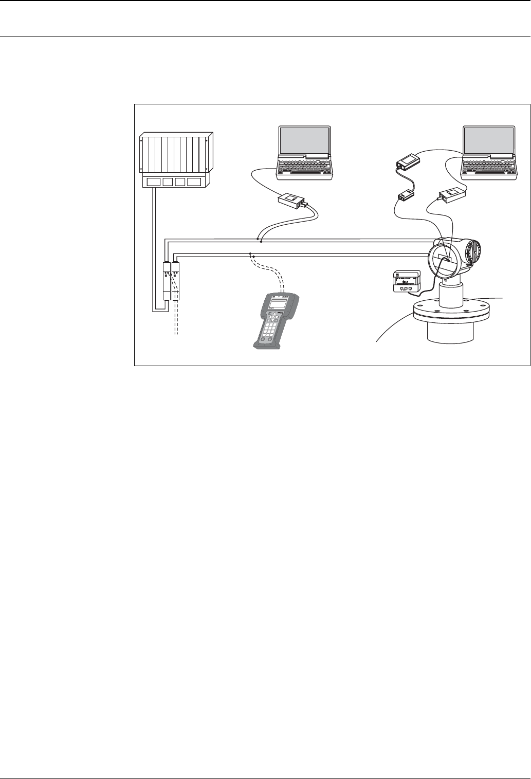
Equipment architecture Stand-alone
The instrument provides a 4…20 mA output with HART protocol.
The complete measuring system consists of:
L00-FMR53xxx-14-00-06-en-002
On-site Configuration
• with display and operating module VU331,
• with a Personal Computer, FXA193 and the operating software "ToF Tool - FieldTool Package" respectively
"FieldCare".
The ToF Tool is a graphical operating software for instruments from Endress+Hauser that operate based on
the time-of-flight principle (radar, ultrasonic, guided micro-impulse). It assists with commissioning, securing
data, trouble shooting and documentation of the measuring point.
Remote Configuration
• with HART handheld DXR375,
• with a Personal Computer, Commubox FXA195 and the operating software "ToF Tool - FieldTool Package"
respectively "FieldCare".
Remote operation
• With a Personal Computer, NRF590 (Tank Side Monitor) and the inventory management software, e.g.
"FuelsManager".
ENDRESS + HAUSER
E
+–
%
1
# % &
Copy
G H I
P Q R S
, ( )‘
A B C
Paste
Page
On
Page
Up
DeleteBksp
Insert
J K L
T UV
_ < >
D E F
Hot Key
+ Hot Key
M N O
W XY Z
+ * /
4
7
.
2
5
8
0
375
FIELD COMMUNICATOR
3
6
9
-
DELTABAR:* * * * * * * *
ONLINE
1 QUICK SETUP
2 OPERATING MENU
4 SV 0 °C
3 PV 352 mbar
HELP SAVE
dsdmdm
df das.
asdas fa
asas la.
Commubox
FXA291 (USB)
ToF Adapter
FXA291
HART
HART
FXA195
or
DXR375
PLC
Commubox
FXA191 (RS232C)
or FXA195 (USB)
service adapter
FXA193 (RS232C)
operating and
display modull
VU331
2x transmitter power
supply unit
RN221N
HART handheld
DXR375
- Fieldcare
- ToF Tool - Field Tool Package
- Fieldcare
- ToF Tool - Field Tool Package
Micropilot S FMR540
Endress+Hauser 5
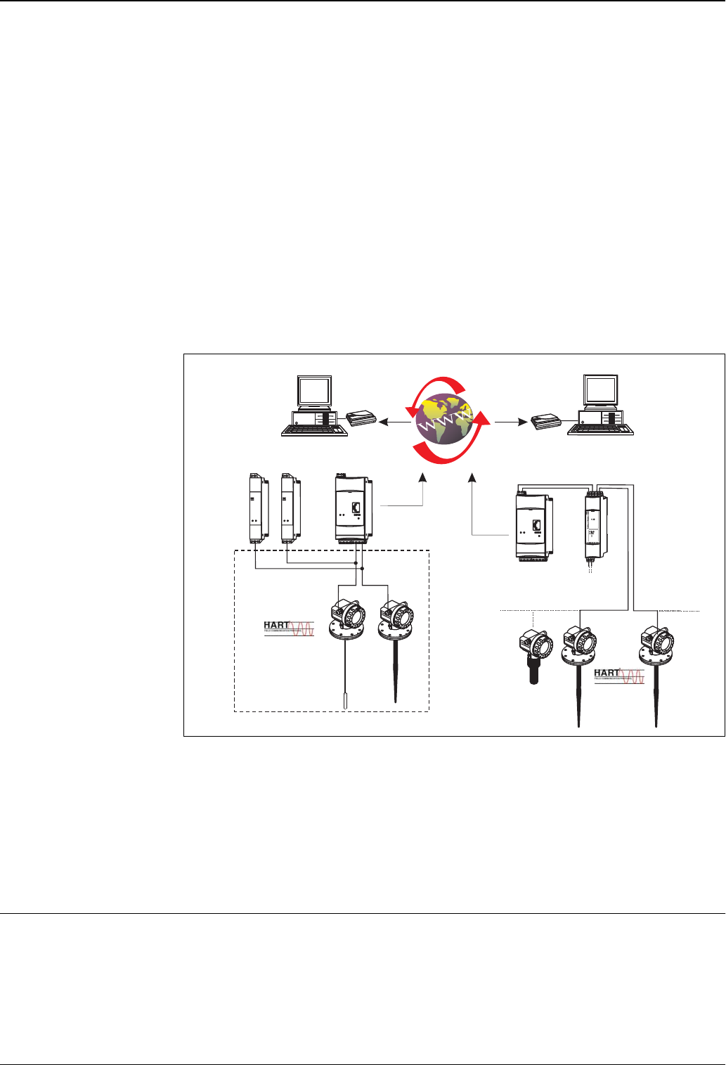
System integration via Fieldgate
Vendor Managed Inventory
By using Fieldgates to interrogate tank or silo levels remotely, suppliers of raw materials can provide their
regular customers with information about the current supplies at any time and, for example, account for them
in their own production planning. For their part, the Fieldgates monitor the configured level limits and, if
required, automatically activate the next supply. The spectrum of options here ranges from a simple purchasing
requisition via e-mail through to fully automatic order administration by coupling XML data into the planning
systems on both sides.
Remote maintenance of measuring equipment
Fieldgates not only transfer the current measured values, they also alert the responsible standby personnel, if
required, via e-mail or SMS. In the event of an alarm or also when performing routine checks, service
technicians can diagnose and configure connected HART devices remotely. All that is required for this is the
corresponding HART operating software (e.g. ToF Tool - FieldTool Package, FieldCare, ...) for the connected
device. Fieldgate passes on the information transparently, so that all options for the respective operating
software are available remotely. Some on-site service operations can be avoided by using remote diagnosis and
remote configuration and all others can at least be better planned and prepared.
L00-FXA520xx-14-00-06-en-009
Note!
The number of instruments which can be connected in mutidrop mode can be calculated by the "FieldNetCalc"
program. A description of this program can be found in Technical Information TI 400F (Multidrop connector
FXN520). The program is available form your Endress+Hauser sales organisation or in the internet at:
"www.endress.com É Download" (Text Search = "Fieldnetcalc").
Integration into the Asset Management System
The HART interface allows the integration into the AMS® (Asset Management System) from Emerson.
Custody transfer applications The Micropilot S is suitable for custody transfer and inventory control applications.The on-site testing has to be
done in compliance with the applicable regulatory standards.The Micropilot S can be sealed after successful on-
site calibration to be protected against any access to the electronics compartment and any changes of software
settings. If the Micropilot S is used for custody transfer or inventory control, any temperature influence on the
tank shell height can be compensated for using the Tank Side Monitor. In addition, the vertical movement of
the gauge reference point due to the hydrostatic tank deformation can be compensated in the Tank Side
Monitor. A Tank Side Monitor can provide 24 VDC for a Micropilot S. The Tank Side Monitor can
communicate with up to 6 devices via HART Multidrop.
-
Fieldgate
FXA520
ENDRESS+HAUSER
RN 221N
ENDRESS+HAUSER
RN 221N
.
Fieldgate
FXA520 20...45 V
DC
FXN 520
FXN 520
Multidrop-Connector
FXN520
HTTP script
Web browser
…
Analogue
Ethernet
GSM
e.g. 2 x RN221N-B …
Channel 1 Channel 2
via HART Client:
- ToF Tool - FieldTool
Package
- FieldCare
...
Remote monitoring
Remote configuration/diagnostics
Micropilot S FMR540
6Endress+Hauser
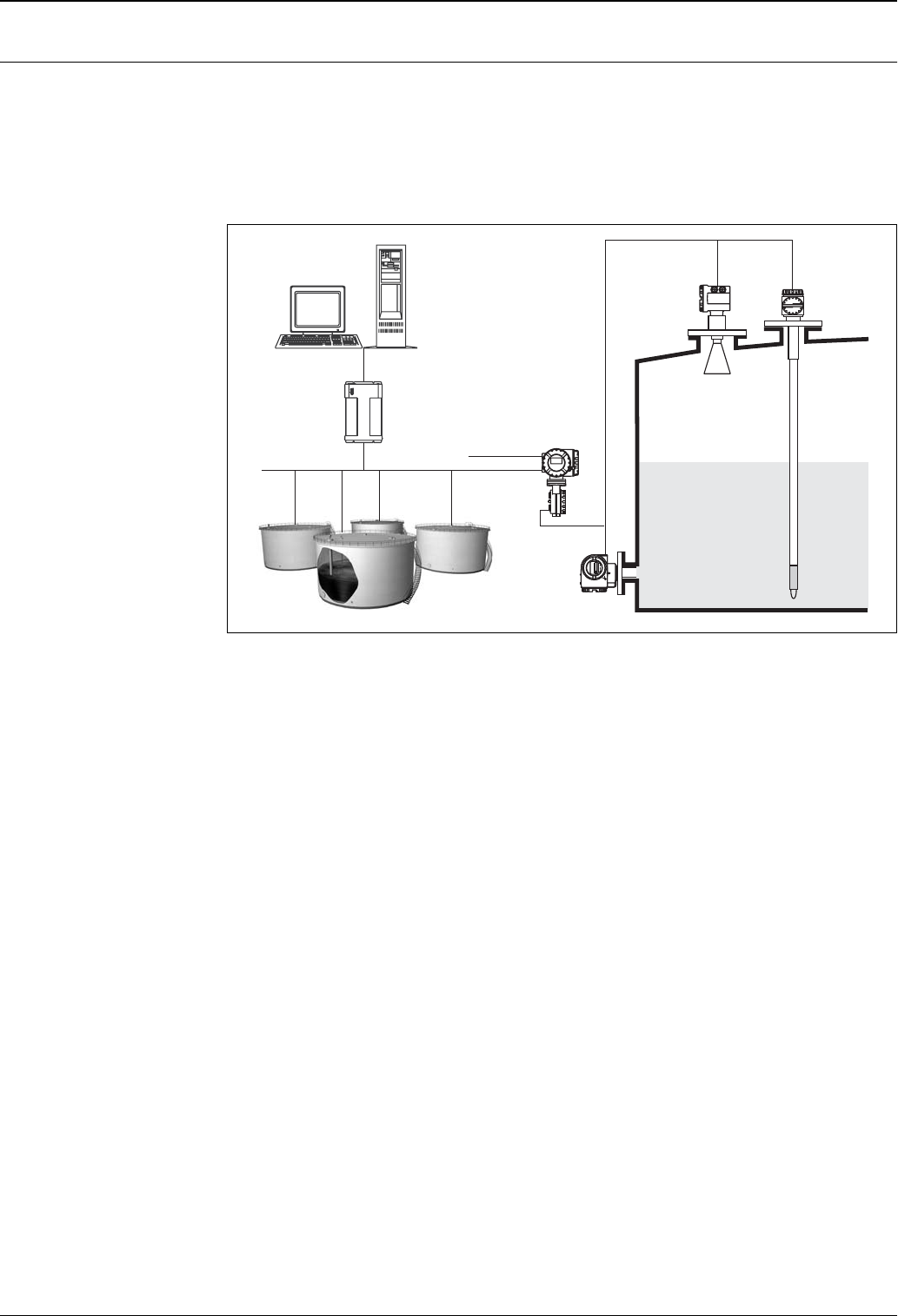
Integrated in tank gauging
system
The Endress+Hauser Tank Side Monitor NRF 590 provides integrated communications for sites with multiple
tanks, each with one or more sensors on the tank, such as radar, spot or average temperature, capacitive probe
for water detection and/or pressure sensors. Multiple protocols out of the Tank Side Monitor guarantee
connectivity to nearly any of the existing industry standard tank gauging protocols. Optional connectivity of
analog 4...20 mA sensors, digital I/O and analog output simplify full tank sensor integration. Use of the proven
concept of the intrinsically safe HART bus for all on-tank sensors yields extremely low wiring costs, while at
the same time providing maximum safety, reliability and data availability.
L00-FMR53xxx-14-00-06-en-004
Micropilot S Prothermo
Tank Side Monitor
Fuels Manager
Software
RTU 8130
(remote
terminal
unit)
Pressure
HART
4 wire
Supply voltage:
16…253 VAC
Micropilot S FMR540
Endress+Hauser 7
Input
Measured variable The measured variable is the distance between the reference point (GRH, refer to fig. →ä3) and a reflective
surface (i.e. medium surface).
The level is calculated based on the tank height entered.The level can be converted into other units (volume,
mass) by means of a linearization. In order to compensate for non-linear effects like movement of the tank roof,
an additional correction table (diptable) can be entered.
Antenna selection for
Micropilot S-series
It is essential for each and every application and installation to select the right antenna type.
The antenna selection depends on the following criteria:
• Type of application (i.e. free space vs. stilling well)
• Installation possibilities (size, location and height of nozzle)
• Properties of the product stored in the tank (radar reflectivitiy, vapor pressure, temperature, etc.)
• The Micropilot S FMR540 offers 2 radar antennas
For stilling well applications, FMR532 should be selected (see TI344F)
For measuring mediums with a low reflectivity (i.e. asphalts, bitumen and etc.), FMR533 should be selected
(see TI344)
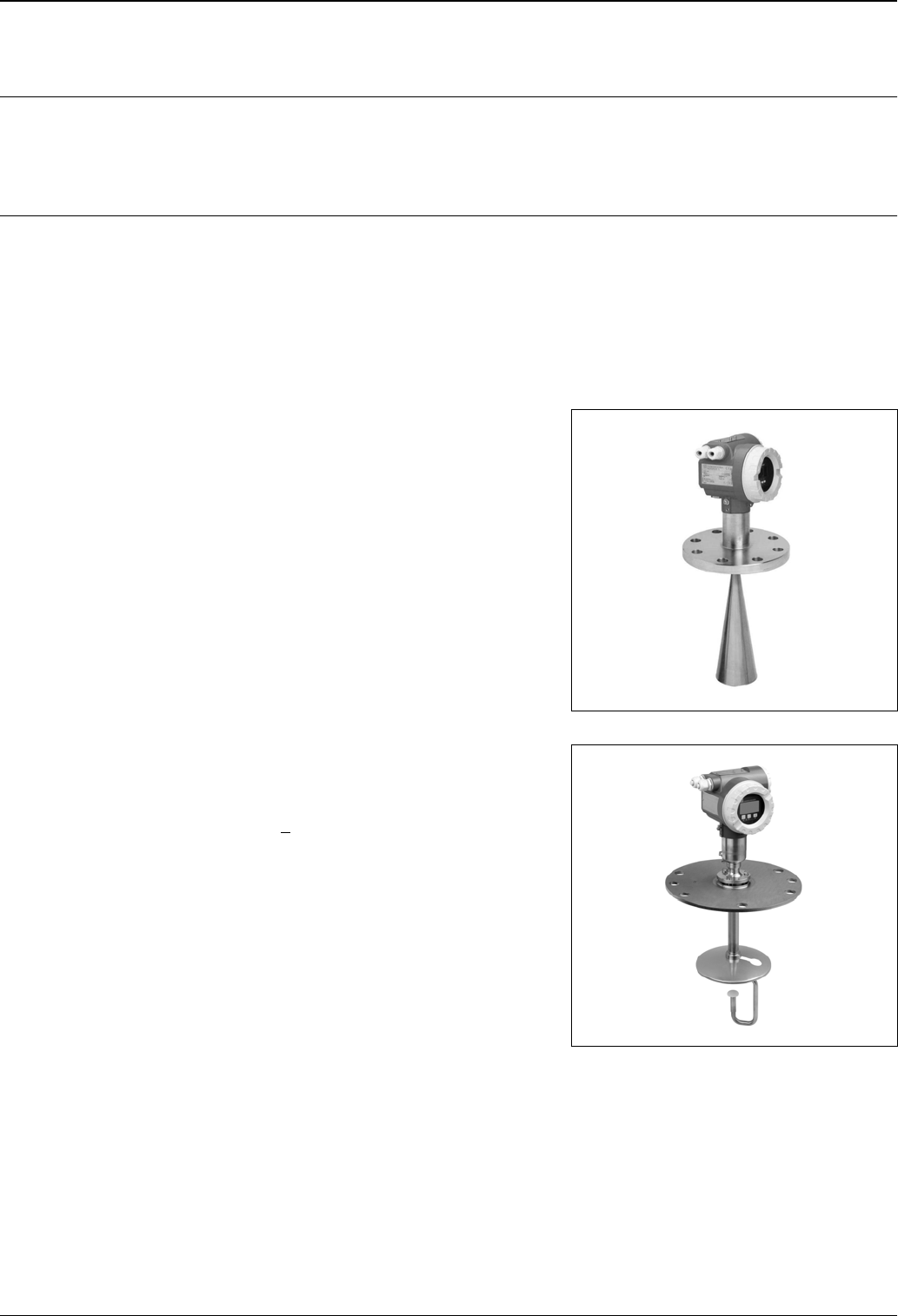
Horn antenna
With DN100 (4") horn, this antenna is suitable for
most of custody transfer applications up to the
measuring distance of 20m/30m (depending on
dielectric constant). With the narrow beam angle (8
deg) , compared to FMR530, this horn antenna is
suitable for closer to tank wall application (→ä15)
When installing, it is essential that the horn extends
below the nozzle (→ä16).
L00-FMR530-10-00-00-yy-001
Parabolic antenna
The parabolic antenna offers the smallest beam angle
(4 deg) for free space applications. It also covers
longest measuring distance of 40m (dielectric
constant > 1.8). It is ideal for applications close to the
tank walls, where nozzles are available. When
installing, it is ideal that the parabolic antenna is
installed in the position where the reflector protrude
from the nozzle (→ä18). For measuring mediums
with a low reflectivity, such as asphalts and bitumen,
FMR533 (please, refer to TI344F) is recommended.
L00-FMR540xx-10-08-06-xx-001
Micropilot S FMR540
8Endress+Hauser
Measuring range The usable measuring range depends on the size of the antenna, the reflectivity of the medium, the mounting
location and possible interference reflections.
To achieve an optimised signal strength it is recommended to use an antenna with as large as possible diameter
(DN200/8" parabolic antenna).
The following tables describe the groups of media as well as the achievable measuring range as a function of
application and media group. If the dielectric constant of a medium is unknown, it is recommended to assume
media group B to ensure a reliable measurement.
Table 1:
The following table describes the media groups and the dielectric constant εr.
Measuring range depending
on sensor type and media
group
Note!
For stilling well applications Micropilot S FMR532 is recommended (see Technical Information TI344F).
Media group DC (εr) Examples
A1.4 ... 1.8 non-conducting liquids, e.g. liquefied gas, ...1)
1) Treat Ammonia NH3 as a medium of group A.
B1.8 ... 4 non-conducting liquids, e.g. benzene, oil, toluene, white products, black products,
crudes, bitumen/asphalts, ...
C4 ... 10 e.g. concentrated acids, organic solvents, esters, aniline, alcohol, acetone, …
D> 10 conducting liquids, e.g. aqueous solutions, dilute acids and alkalis
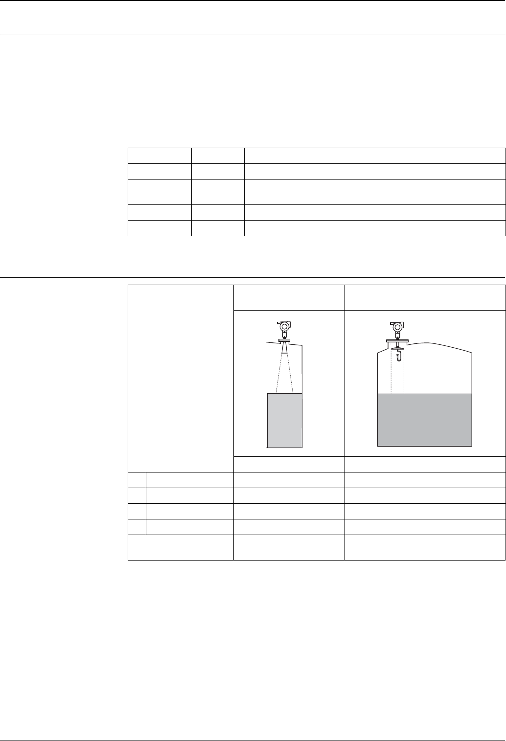
Media group Horn antenna
without sensor extension
Parabolic antenna
without sensor extension
Measuring range Measuring range
ADC (εr) = 1.4 ... 1.8 −−
BDC (εr) = 1.8 ... 4 0.6 ... 20 m 0.8 ... 40 m
CDC (εr) = 4...10 0.6 ... 30 m 0.8 ... 40 m
DDC (εr) > 10 0.6 ... 30 m 0.8 ... 40 m
Max. measuring range with
cudstody transfer approval
NMi: 20 m / 65 ft
PTB: 20 m / 65 ft
NMi: 25 m / 82 ft
PTB: 30 m / 98 ft
Micropilot S FMR540
Endress+Hauser 9
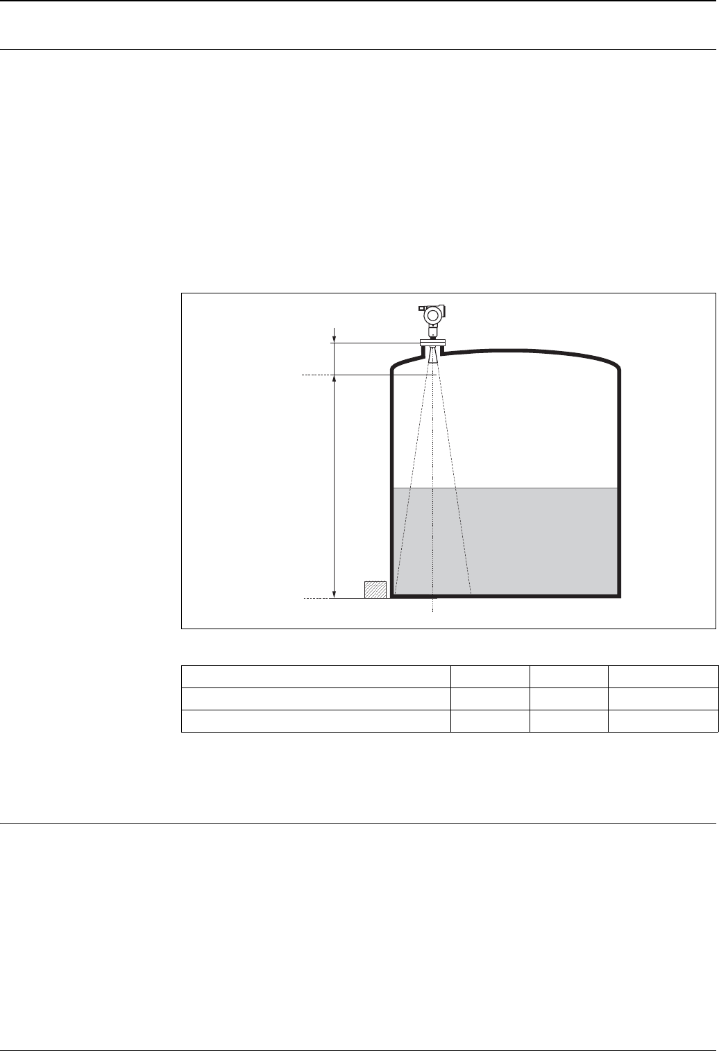
Measuring conditions • The measuring range begins, where the beam hits the tank bottom. Particularly with dish bottoms or conical
outlets the level cannot be detected below this point.
• In case of media with a low dielectric constant (groups A and B), the tank bottom can be visible through the
medium at low levels (low height C). Reduced accuracy has to be expected in this range. If this is not
acceptable, we recommend positioning the zero point at a distance C (see Fig.) above the tank bottom in
these applications.
• In principle it is possible to measure up to the tip of the antenna with FMR540. However, due to
considerations regarding corrosion and build-up, the end of the measuring range should not be chosen any
closer than A (see Fig.).
•B requests the smallest possible measuring range (see fig.).
• Tank diameter and height should be at least dimensioned such that a reflection of the radar signal on both
sides of the tank can be avoided.
• Depending on its consistence, foam can either absorb microwaves or reflect them off the foam surface.
Measurement is possible under certain conditions.
L00-FMR54xxx-17-00-00-yy-009
Behaviour if measuring range is exceeded
The behaviour in case of the measuring range being exceeded can be freely set: the default setting is a current
of 22 mA and the generation of a digital warning (E651).
Operating frequency • FMR540: 26 GHz ultra wideband system
A [m (inch)] B [m (inch)] C [mm (inch)]
FMR540 (Horn Antenna without extension) 0.6 (23.6) > 0.5 (> 20) > 300 (> 12)
FMR540 (parabolic Antenna without extension) 0.8 (31.5) > 0.5 (> 20) > 300 (> 12)
100%
0%
B
A
C
Micropilot S FMR540
10 Endress+Hauser
Output
Output signal • 4…20 mA with HART protocol (e.g. for multidrop connection to the Tank Side Monitor NRF590): this
version can be operated via the PC operating software ToF Tool and FieldCare. The instrument supports both
point-to-point and multidrop operation.
Signal on alarm Error information can be accessed via the following interfaces:
• Local display:
– Error symbol
– Plain text display
– LED’s: red LED continuously on = alarm, red LED flashes = warning
• Current output
• Digital interface
Linearization The linearization function of the Micropilot S allows the conversion of the measured value into any unit of
length or volume. Linearization tables for calculating the volume in cylindrical tanks are pre-programmed.
Other tables of up to 32 value pairs can be entered manually or semi-automatically.
Galvanic isolation 500 V towards ground.
500 V between power supply and signal.
Auxiliary energy
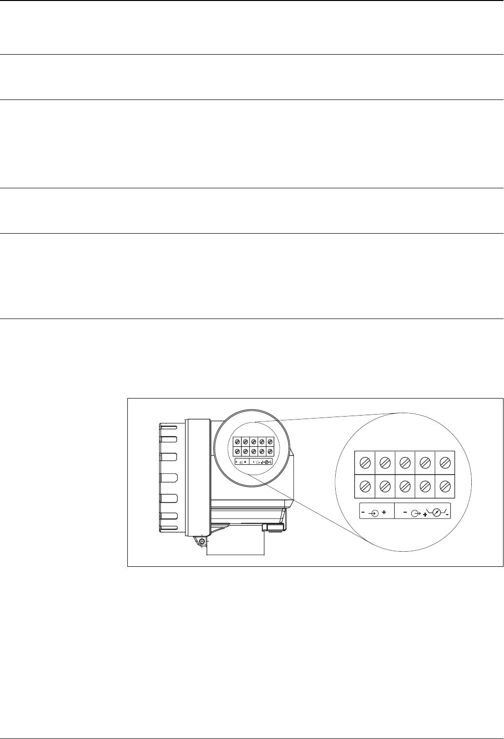
Electrical connection Terminal compartment
• Aluminium housing T12 with separate terminal compartment for:
– standard,
– EEx ia (with overvoltage protection),
The electronics and current output are galvanically isolated from the antenna circuit.
L00-FMR53xxx-04-00-00-en-001
13
2
4
4
5
5
13
2
45
power supply signal
Micropilot S FMR540
Endress+Hauser 11
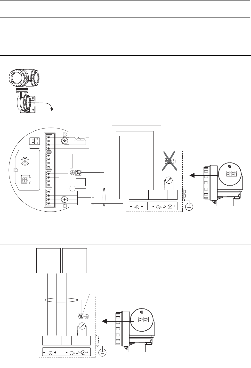
Terminal assignment 4…20
mA with HART
The 4-wire cable is connected to the screw terminals (wire diameter 0.5…2.5 mm) in the terminal
compartment. Use 4-wire twisted pair cable with screen for the connection.Protective circuitry against reverse
polarity, RFI, and over-voltage peaks is built into the device (refer to TI241F »basics for EMC-tests«). Refer to
TI374F for connection to the Tank Side Monitor NRF590.
Connection to Tank Side Monitor NRF590
l00-fmr54xxx-04-00-00-en-002
Connection as a stand alone device
l00-fmr54xxx-04-00-00-en-001
12345
13
2
45
RTD
NRF 590 i.s. terminal board
i.s. module wiring
HART
sensor
+
-
-
+
16
17
18
19
D+
S+
S-
D-
20
21
22
23
OPT1
OPT2
OPT3
OPT4
24
25
26
27
+
-
+
H
H
-
+
-
+
P
H
-
28
29
30
31
For Micropilot
S-series only!
Internally
interconnected
as one HART
fieldbus loop
2
1
4
3
12 34
plant
ground
grounding not on
Micropilot S
grounding single sided
on Tank Side Monitor
NRF590
The Micropilot S is - possibly in combination with other devices - connected
to a tank side monitor in a hazardous area. In this case, it is recommended
that you ground the cable screen centrally at the and
connect all devices to the same potential matching line (PML). If, for functional
reasons, a capacitive coupling is required between local earth and screen
(multiple grounding), ceramic condensers with a dielectric strength of min. 1500 V
must be used, whereby the total capacitance of 10 nF must not be exceeded.
Notes on grounding interconnected intrinsically safe devices are provided by
the FISCO model.
Tank Side Monitor
eff
intrinsicaly safe
terminal board
Tank Side Monitor
NRF590
only for
Micropilot S
5
12 34
12345
13
2
45
plant
ground
power:
24 VDC
(16…30 V)
signal:
24 VDC
A Micropilot S situated in a hazardous area is connected as a
to a situated outside of the
hazardous area. In this case, it is recommended that the screen be
connected directly to the Micropilot at the housing's earth, whereby
the Micropilot S and the power supply unit are connected to the same
potential matching line (PML).
single
device power supply unit and transmitter

Micropilot S FMR540
12 Endress+Hauser
Load HART Minimum load for HART communication: 250 Ω
Cable entry Cable gland: M20x1.5
Cable entry: G ½, ½ NPT, M20 (thread)
Supply voltage DC voltage: 16…36 V
Power consumption Max. 400 mW at 16 V, max. 600 mW at 24 V, max. 750 mW at 30 V.
Current consumption Max. 25 mA (55 mA inrush current).
Residual ripple HART 47...125 Hz: Upp = 200 mV
Max noise HART 500 Hz...10 kHz : Ueff = 19 mV (at 500 Ω)
Power supply For stand alone operation recommended via two Endress+Hauser RN221N.
mm accuracy For measurements with mm accuracy the measured variable must be transmitted using HART protocol to
ensure the necessary resolution.
Overvoltage protector • The level transmitter Micropilot S is equipped with an internal overvoltage protector (600 Vrms surge
arrester) according to DIN EN 60079-14 or IEC 60060-1 (impulse current test 8/20 μs, Î = 10 kA, 10
pulses). Additionally, the instrument is protected by a galvanic insulation of 500 Vrms between the power
supply and the (HART) current ouput. Connect the metallic housing of the Micropilot S to the tank wall or
screen directly with an electrically conductive lead to ensure reliable potential matching.
• Installation with additional overvoltage protector HAW262Z/HAW56xZ (see XA081F-A "Safety instructions
for electrical apparatus certified for use in explosion-hazardous areas").
– Connect the external overvoltage protector and the Micropilot S transmitter to the local potential
matching system.
– Potentials shall be equalised both inside and outside the explosion hazardous area.
– The cable connecting the overvoltage protector and the Micropilot S transmitter shall not exceed 1 m in
length;
– The cable shall be protected e.g. routed in an armoured hose.
Communication Terminal voltage minimal maximal
Power supply standard U (20 mA) = 16 V 36 V
Ex U (20 mA) = 16 V 30 V
Signal Ex U (4 mA) = 11.5 V 30 V
U (20 mA) = 11.5 V 30 V

Micropilot S FMR540
Endress+Hauser 13
Performance characteristics
Note Performance characteristics for instruments that can be calibrated for inventory control and custody transfer
applications are ccording to weight & measure standards in compliance with OIML R85.General operating /
environmental conditions see →ä19.
Reference operating
conditions
According to OIML R85:
• Temperature = –25…+55 °C (-13…+131 °F)
• Atmospheric pressure
• Relative humidity (air) = 60 % ±15%
• Medium properties: e.g. medium with good reflectivity and calm surface.
• Tank diameter: signal beam hits the tank wall only at one side.
• No major interference reflections inside the signal beam.
Maximum measured error Absolute accuracy: better than ±1 mm (better than 1/16")
Software reliability The software used in the radar instruments FMR540 fulfills the requirements of OIML R85. This particularly
includes:
• cyclical test of data consistency
• non-volatile memory
• segmented data storage
The radar instruments Micropilot S continuously monitor the compliance with accuracy requirements for
custody transfer measurements according to OIML R85. If the accuracy cannot be maintained, a specific alarm
is generated on the local display and via the digital communication (see →ä25).
Hysteresis 0.1 mm
Long-term drift The long-term drift is within the specified accuracy.
Influence of ambiente tempe-
rature
Current output (additional error, in reference to the span of 16 mA):
•Zero point (4 mA)
average TK: 0,025 %/10 K, max. 0,291 % over the entire temperature range -40 °C...+80 °C
•Span (20 mA)
average TK: 0,07 %/10 K, max. 0,824 % over the entire temperature range -40 °C...+80 °C
Proof of accuracy of custody
transfer versions
The accuracy of each Micropilot S is established through a calibration certificate that records the absolute and
relative error at 10 equidistant points during the final test. A Laser Interferometer (Jenaer Messtechnik ZLM
500) with an absolute accuracy of 0.1 mm is used as a reference for the free space measurements with
FMR540.
Additional initial factory verifications for custody applications are available on demand for all radar instruments
FMR540.
Non-repeatability 0.1 mm (1/64")
Resolution Digital 0.1 mm / analogue (4...20 mA): 0.03 % of measuring range
Inventory control versions All device types can be delivered as "Inventory Conctrol Versions" with a reduced accuracy of
± 3mm (under reference conditions). To these versions, the calibration certificate or custody transfer type
approval is NOT attached. The "Inventory Control Versions" can be selected by choosing the option "R" -
reduced accuracy" in the order code option »Custody transfer approvals« →ä31.
Micropilot S FMR540
14 Endress+Hauser
Operating conditions: Installation
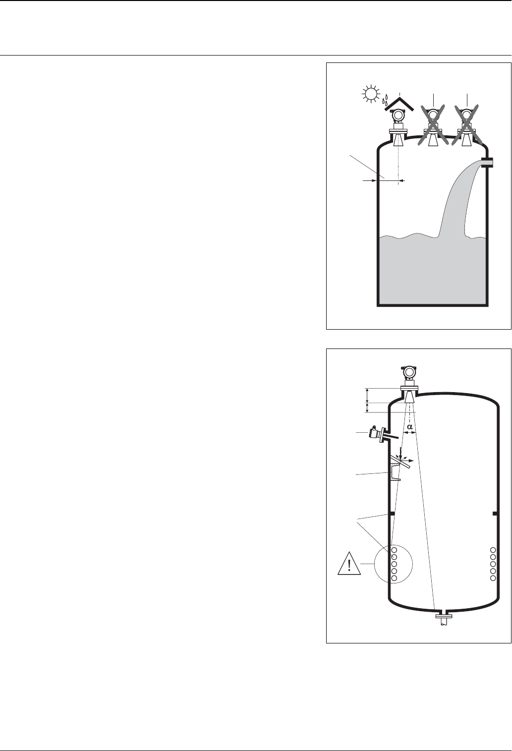
Installation instructions Orientation
• Recommended distance (1) from tank wall to the
center of the nozzle: minimum as specified in Table
on →ä15 (beam angle / distance to wall).
• Not in the centre (3), interference can cause signal
loss.
• Not above the fill stream (4).
• It is recommended to use a weather protection
cover (2) in order to protect the transmitter from
direct sun or rain. Assembly and disassembly is
simply done by means of a tension clamp (see
Accessories on →ä32).
L00-FMR54xxx-17-00-00-yy-012
1
234
Tank installations
• Avoid any installations (1), like limit switches, tem-
perature sensors, etc., inside the signal beam (refer
to beam angle →ä15).
• It is essential that HiHi alarm is below the blocking
distance (BD) and the safety distance (SD).
• Symmetrical installations (2), e.g. vacuum rings,
heating coils, baffles, etc., can also interfere with
the measurement.
Optimisation options
• Antenna size: the bigger the antenna, the smaller
the beam angle, the less interference echoes.
• Mapping: the measurement can be optimized by
means of electronic suppression of interference
echoes.
• Antenna alignment: refer to "optimum mounting
position" (→ä16).
• Stilling well: a stilling well can always be used to
avoid interference. The FMR532 with planar
antenna is recommended for stilling wells with a
diameter DN150 (6”) and larger.
• Metallic screens (3) mounted at a slope spread the
radar signals and can, therefore, reduce interfe-
rence echoes.
Please contact Endress+Hauser for further informa-
tion.
L00-FMR54xxx-17-00-00-yy-013
1
3
2
BD
SD
Micropilot S FMR540
Endress+Hauser 15
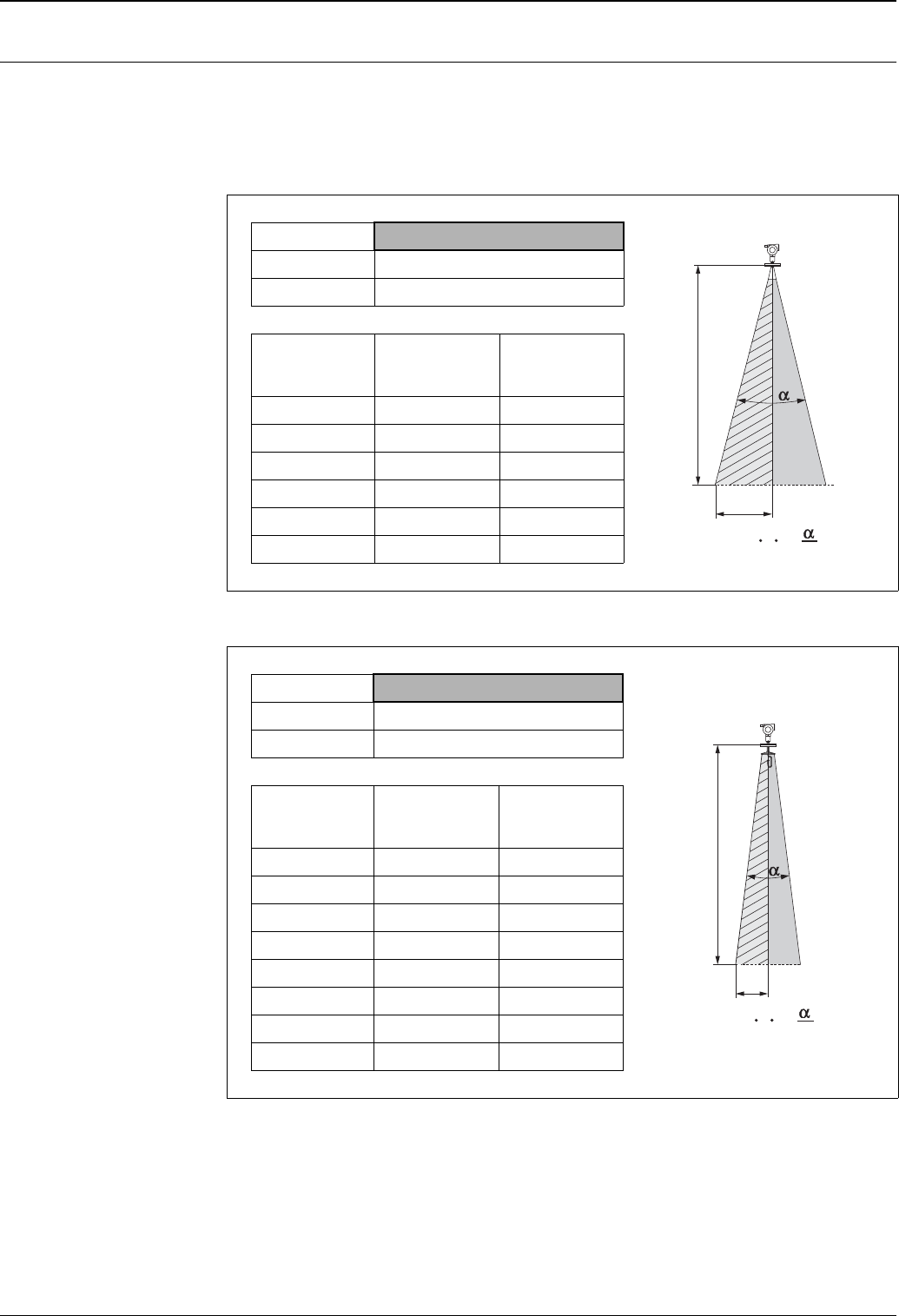
Beam angle The beam angle is defined as the angle a where the energy density of the radar waves reaches half the value of
the maximum energy density (3dB-width). Microwaves are also emitted outside the signal beam and can be
reflected off interfering installations. Beam diameter W is a function of antenna type (beam angle α) and
measuring distance D. The distance between the tank wall and the center of the sensor should be greater than
W/2. It is strongly recommended to avoid any mechanical obstacles within the highlighted area.
Horn antenna
L00-FMR54xxx-14-00-00-xx-003
Antenna size 100 mm / 4"
Beam angle (α)8°
Measuring
distance (D)
Beamwidth
diameter (W)
Recommended
distance to wall
(W/2)
5 m / 16 ft 0.70 m / 2.24 ft 0.35 m
10 m / 32 ft 1.40 m / 4.48 ft 0.70 m
15 m / 49 ft 2.10 m / 6.85 ft 1.05 m
20 m / 65 ft 2.80 m / 9.09 ft 1.40 m
25 m / 82ft 3.50 m / 11.48 ft 1.75 m
30 m / 98 ft 4.20 m / 13.71 ft 2.10 m
Parabolic antenna
L00-FMR54xxx-14-00-00-xx-004
Antenna size 200 mm / 8"
Beam angle (α)4°
Measuring
distance (D)
Beamwidth
diameter (W)
Recommended
distance to wall
(W/2)
5 m / 16 ft 0.35 m / 1.12 ft 0.18 m
10 m / 32 ft 0.70 m / 2.23 ft 0.35 m
15 m / 49 ft 1.05 m / 3.42 ft 0.53 m
20 m / 65 ft 1.40 m / 4.54 ft 0.70 m
25 m / 82ft 1.7 m / 5.58 ft 0.85 m
30 m / 98 ft 2.10 m / 6.84 ft 1.05 m
35 m / 115 ft 2.45 m / 8.04 ft 1.23 m
40 m / 131 ft 2.80 m / 9.15 ft 1.40 m
D
W/2
W = 2 D tan 2
D
W/2
W = 2 D tan 2
Micropilot S FMR540
16 Endress+Hauser
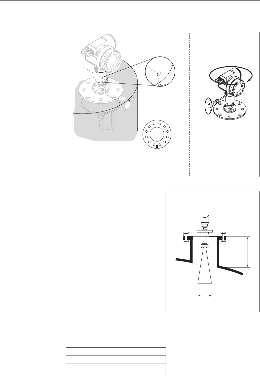
Installation on tank FMR540 Optimum mounting position
L00-FMR54xxx-17-00-00-en-010
90°
90°
Maker if using
ANSI, DIN or
JIS flanges
Marker if using
Endress+Hauser UNI flange
Turn housing
allen key
4 mm/0.1”
The housing can be turned in
order to simplify access to the display
and the terminal compartment
Standard installation FMR540 with horn
antenna
• Observe installation instructions on Page 14.
• Marker is aligned towards tank wall.
• The marker is always exactly in the middle
between two bolt-holes in the flange.
• After mounting, the housing can be turned 350° in
order to simplify access to the display and the
terminal compartment.
• Adjust vertical sensor alignment in case the flange
is not parallel to the face is medium surface.
• The horn antenna should protrude from the nozzle.
If necessary, choose version with antenna
extension (→ä21).
Note!
Please contact Endress+Hauser for application with
higher nozzle.
• The horn antenna should be installed with 1 degree
inclination towards the tank center.
To avoid interference reflections or for optimum
alignment within the tank, the FMR540 with
optional top target positioner can be swiveled by
15° in all directions. For more informations please
see instructions in KA274F/00.
Please contact Endress+Hauser Service
Organisation for commisioning.
L00-FMR250xx-17-00-00-en-004
H
ØD
Antenna size 100 mm / 4"
D [mm / inch] 95 / 3.7
H [mm / inch]
(without antenna extension) < 430 / < 19.2
Micropilot S FMR540
Endress+Hauser 17
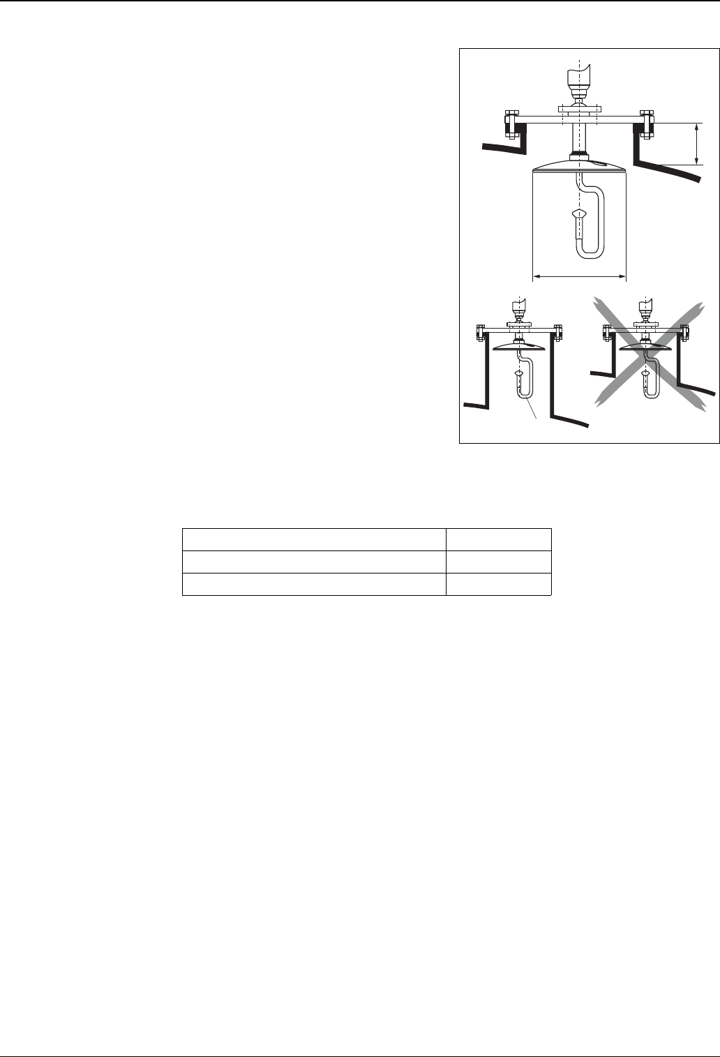
Standard installation FMR540 with parabolic
antenna
• Observe installation instructions on Page 14.
• Marker is aligned towards tank wall.
• The marker is always exactly in the middle
between two bolt-holes in the flange.
• After mounting, the housing can be turned 350° in
order to simplify access to the display and the
terminal compartment.
• Ideally the parabolic antenna should protrude from
the nozzle (1). If necessary, choose version with
antenna extension (→ä21).
Particularly when using the top target positioner,
please ensure that the parabolic reflector is
protruding from the nozzle/roof so as not to inhibit
alignment.
Note!
For application with higher nozzle install parabolic
antenna completely in the nozzle (2), including
RF-wave guide (3).
• The parabolic antenna should be installed
vertically.
To avoid interference reflections or for optimum
alignment within the tank, the FMR540 with
optional top target positioner can be swiveled by
15° in all directions. For more informations please
see instructions in KA274F/00. Please, contact
Endress+Hauser Service organization for
commissioning.
L00-FMR54xxx-17-00-00-en-004
H
ØD
1
2
3
Antenna size 200 mm / 8"
D [mm / inch] 197 / 7.75
H [mm / inch] (without antenna extension) < 50 / < 1.96
Micropilot S FMR540
18 Endress+Hauser
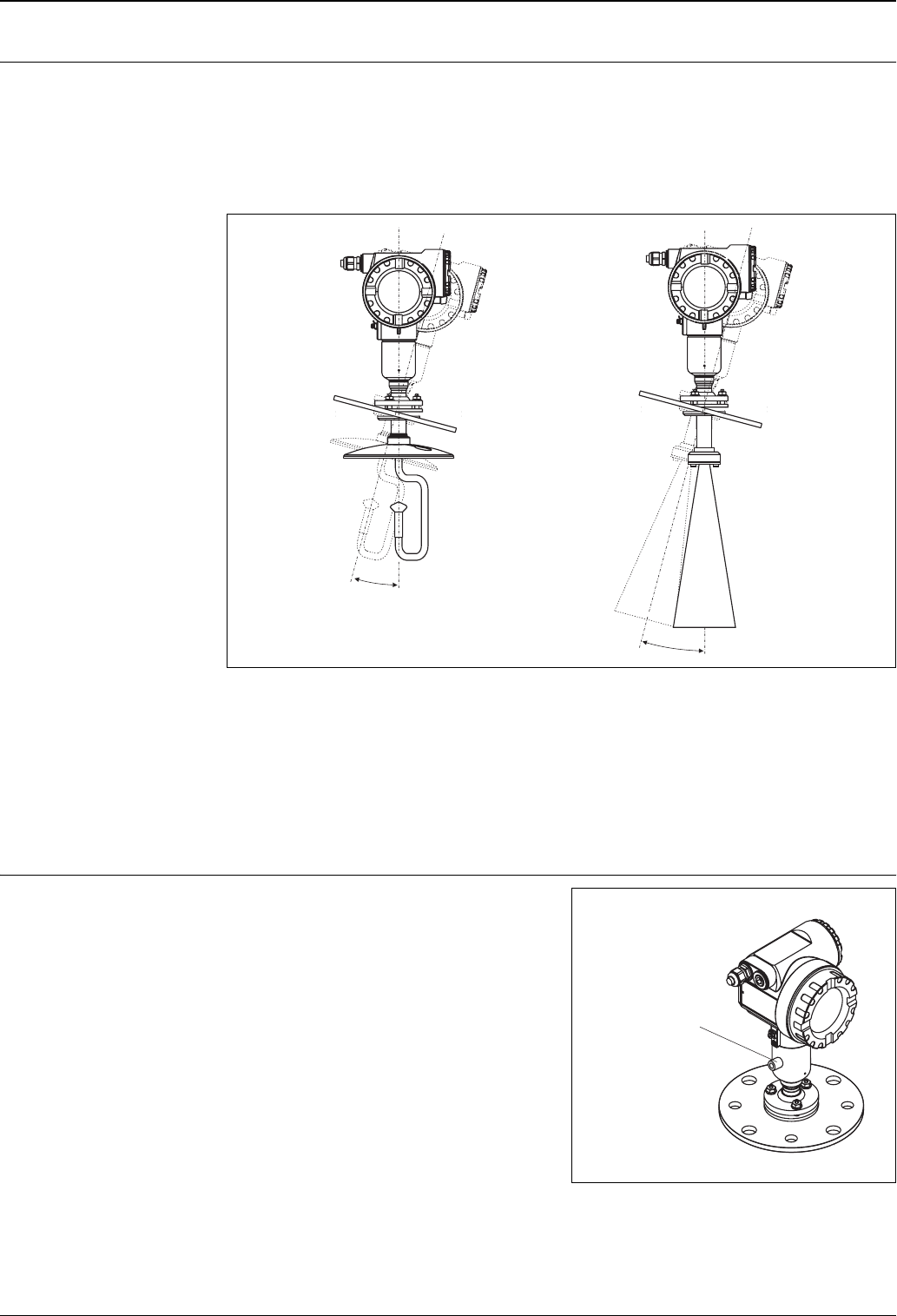
FMR540 with top target
positioner
Optimum mounting position
Micropilot S should be installed vertically towards the Liquid surface for best measuring performance of
±1 mm. Using top target positioner it is possible to tilt the antenna axis by up to 15° in all directions. The top
target positioner is used for the optimum alignment of the radar beam to the liquid surface.
The Sensor should be positioned vertical to the liquid surface in inclination of 0° for Parabolic Antenna and
1° for Horn Antenna.
L00-FMR54xxx-17-00-00-en-006
Align antenna axis:
1. Loosen screws.
2. Align antenna axis (here this is possible up to max. ±15° in all directions).
3. Tighten screws.
For more informations please see instructions in KA274F/00.
In case of custody Application, the screws must be locked with wires.
Integrated air purge
connection
±15° ±15°
In some applications, the integrated air purge
connection can prevent clogging of the antenna.
• Permanent operation:
recommended pressure range of the purge air:
1.2...1.5 bar abs.
• Pulsed operation:
max. pressure of purge air: 6 bar abs.
Caution!
Make sure to use dry purge air.
L00-FMR54xxx-17-00-00-en-007
air purge connection:
G (max. torque 3.5 Nm)¼

Micropilot S FMR540
Endress+Hauser 19
Operating conditions: Environment
Ambient temperature range Ambient temperature for the transmitter:
• Standard: -40 °C ... +80 °C (-40 °F…+176 °F)
• For calibration to regulatory standards: -25 °C ... +60 °C (-30 °F…+140 °F)
With Tu<-20 °C and Tu>+60 °C the operability of the LC-display is reduced.A weather protection cover
should be used for outdoor operation if the instrument is exposed to direct sunlight.
Storage temperature -40 °C ... +80 °C (-40 °F…+176 °F)
Climate class DIN EN 60068-2-38 (test Z/AD)
Degree of protection • Transmitter: IP 68, NEMA 6P. With open housing: IP20, NEMA 1.
• Antenna: IP 68 (NEMA 6P)
Vibration resistance DIN EN 60068-2-64 / IEC 68-2-64: 20…2000 Hz, 1 (m/s2)/Hz
Cleaning of the antenna The antenna can get contaminated, depending on the application. The emission and reception of microwaves
can thus eventually be hindered. The degree of contamination leading to an error depends on the medium and
the reflectivity, mainly determined by the dielectric constant εr. If the medium tends to cause contamination
and deposits, cleaning on a regular basis is recommended. Care has to be taken not to damage the antenna in
the process of a mechanical or hose-down cleaning. The material compatibility has to be considered if cleaning
agents are used! The maximum permitted temperature at the flange should not be exceeded. .
Electromagnetic compatibility • Interference Emission to EN 61326, Electrical Equipment Class B
• Interference Immunity to EN 61326, Annex A (Industrial) and NAMUR Recommendation NE 21 (EMC)
• A standard installation cable is sufficient if only the analogue signal is used. Use a screened cable when
working with a superimposed communications signal (HART).
Approvals for custody transfer
applications
All aspects of OIML R85 are fulfilled.
Operating conditions: Process
Process temperature range FKM Viton GLT, -40 °C...+200 °C (-40 °F...+392 °F)
Process pressure limits • Parabolic Antenna -1...6 bar (-14.5...87 psi)
• Horn Antenna -1...16 bar (-14.5 psi...232 psi)
• With Endress+Hauser UNI flange -1...1bar (-14.5 psi...14.5 psi)
Antenna core • Parabolic Antenna: Teflon (PTFE)
• Horn Antenna: PEEK
Wetted parts • Parabolic Antenna: Teflon (PTFE), seal and 316L/1.4404/1.4435
• Horn Antenna: PEEK, seal and 316L/1.4404/1.4435
Optional (top target
positioner)
± 15° inclination seal: FKM Viton GLT
Micropilot S FMR540
Endress+Hauser 21
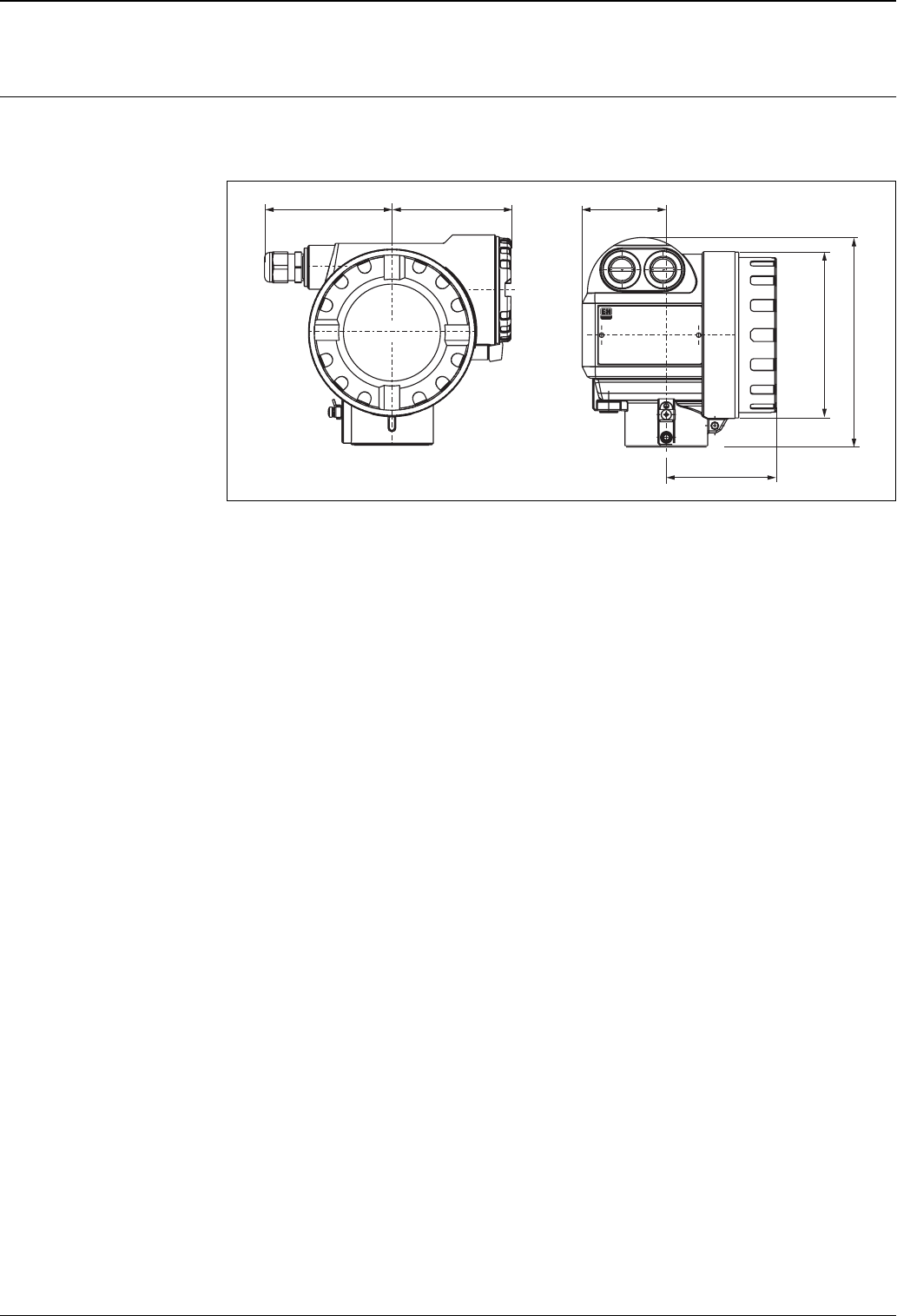
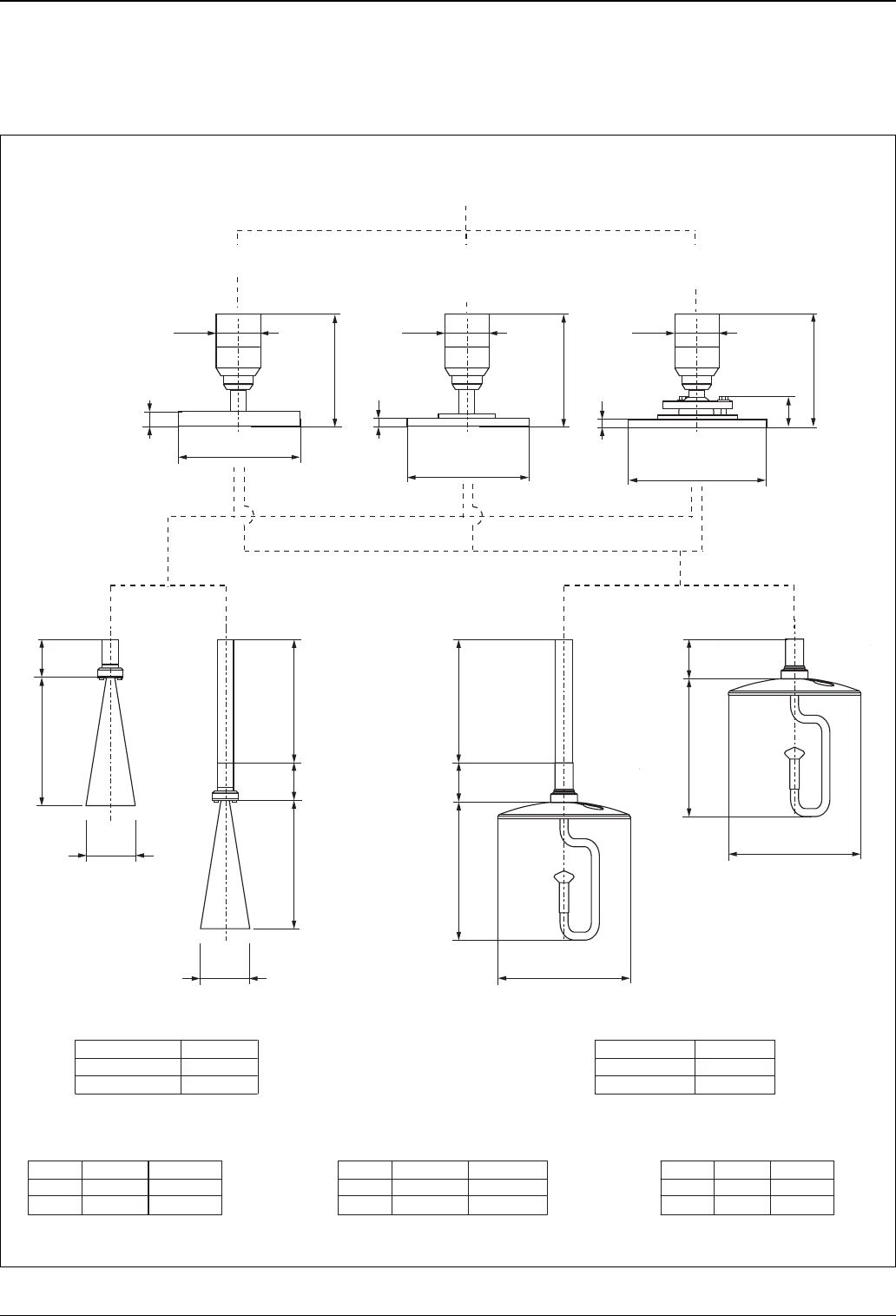
Micropilot M FMR540 - process connection, type of antenna
Housing dimensions →ä20.
L00-FMR540xx-06-00-00-en-001
L
L
L
L
50
50
135
40
135
135
50
50
Ød
Ød
Ød
150/250/450
150/250/450
200mm/8”
95 197
430 195
100mm/4”
b [mm] b [mm]b [mm]
L [mm] L [mm]
d [mm] d [mm]
D [mm] D [mm]D [mm]
220 285 210 280228.6 279.4
20 22 18 2223.9 25.4
DN 100 DN 150 DN 100 DN 1504” 6”
ØD
Ø 280 (DN 150)
Ø
Ø 405 (DN 250)
340 (DN 200)
b
8
8
Ø60
Ø60
Ø60
Ød
Parabolic antennaHorn antenna
for 10K
Flange
Flange to JIS B2220
for 150 lbs
Flange
Flange to ASME B16.5
for PN10/16
Antenna size Antenna size
Horn antenna Parabolic antenna
Flange
Flange to EN 1092-1 (agreeable to DIN 2527)
T12 housing
Flange DN100…150
or equivalent
Top Taget Positioner
(Sensor Alignment) with
Endress+Hauser UNI flange DN 200/250
Endress+Hauser UNI flange
DN 150
DN 200
DN 250
Ø 280 (DN 150)
Ø 340 (DN 200)
Ø 405 (DN 250)
Micropilot S FMR540
22 Endress+Hauser
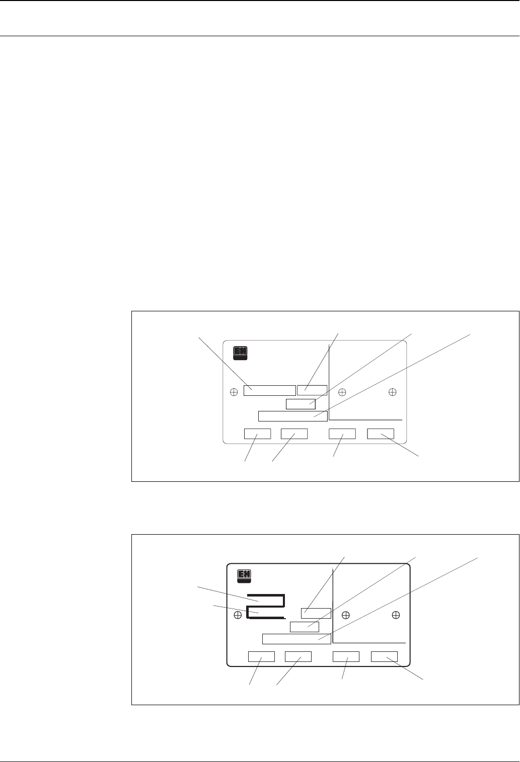
Type plate / type plate for
custody transfer applications
In addition to the standard type plate, the instrument features a type plate for custody transfer applications with
the following statements:
• manufacturer
• instrument type
• label for custody transfer approval
PTB :„Z“ with approval number and issuing agency, the 4-digit approval number is shown in the upper part
of the „Z“, the lower part shows year and month of type approval.
NMi : field for 5-digit approval number
• year of manufacturing
• space for imprinted tank identification number
• statement of measuring range suitable for custody transfer approval including unit
• statement of ambient temperature range suitable for calibration to regulatory standards
The following statements are also required for calibration to regulatory standards. They are listed on the
standard type plate and are not repeated here:
• date of manufacturing
•tester
The type plate for calibration to regulatory standards can be sealed. It is mounted with screws, therefore also
available as a spare part. The „stamping“ of the electronic compartment is achieved with the custody locking
switch (compare figure on →ä25) and does not require any additional stamping location. NMI and PTB type
plate for custody transfer approval refer to illustration:
NMi type plate (example)
L00-FMR540xx-18-00-00-en-001
PTB type plate (example)
L00-FMR540xx-18-00-00-en-002
ENDRESS+HAUSER
MICROPILOT S FMR
MICROPILOT S FMR
Hersteller / Producer :
Hersteller / Producer :
Zert.Messbereich/Cert.Measuring range
Zert.Messbereich/Cert.Measuring range
Umgeb./Environm.
Umgeb./Environm.
bis
to
min
max
von
from
Baujahr
Y
ear of constr.
ear of constr.
Zertifikat-Nr.
Certification no.
T
m°C
Tank-Nr.
Tank-no.
Tankreferenzhöhe
Tank reference height
m
250002069--
Certification no
Certificated
Measuring range from ... to ... min. environment temperature max. environment temperature
Year of construction Tank reference height Tank-no.
ENDRESS+HAUSER
MICROPILOT S FMR
Hersteller / Producer :
Zert.Messbereich/Cert.Measuring range Umgeb./Environm.
bis
to min max
von
from
Baujahr
Year of constr.
T
m°C
Tank-Nr.
Tank-no.
Tankreferenzhöhe
Tank reference height
m
250002069--
Certificated
Measuring range from ... to ... min. environment temperature max. environment temperature
Year of construction Tank reference height Tank-no.
Approval number
Year and month
of type approval
Micropilot S FMR540
Endress+Hauser 23
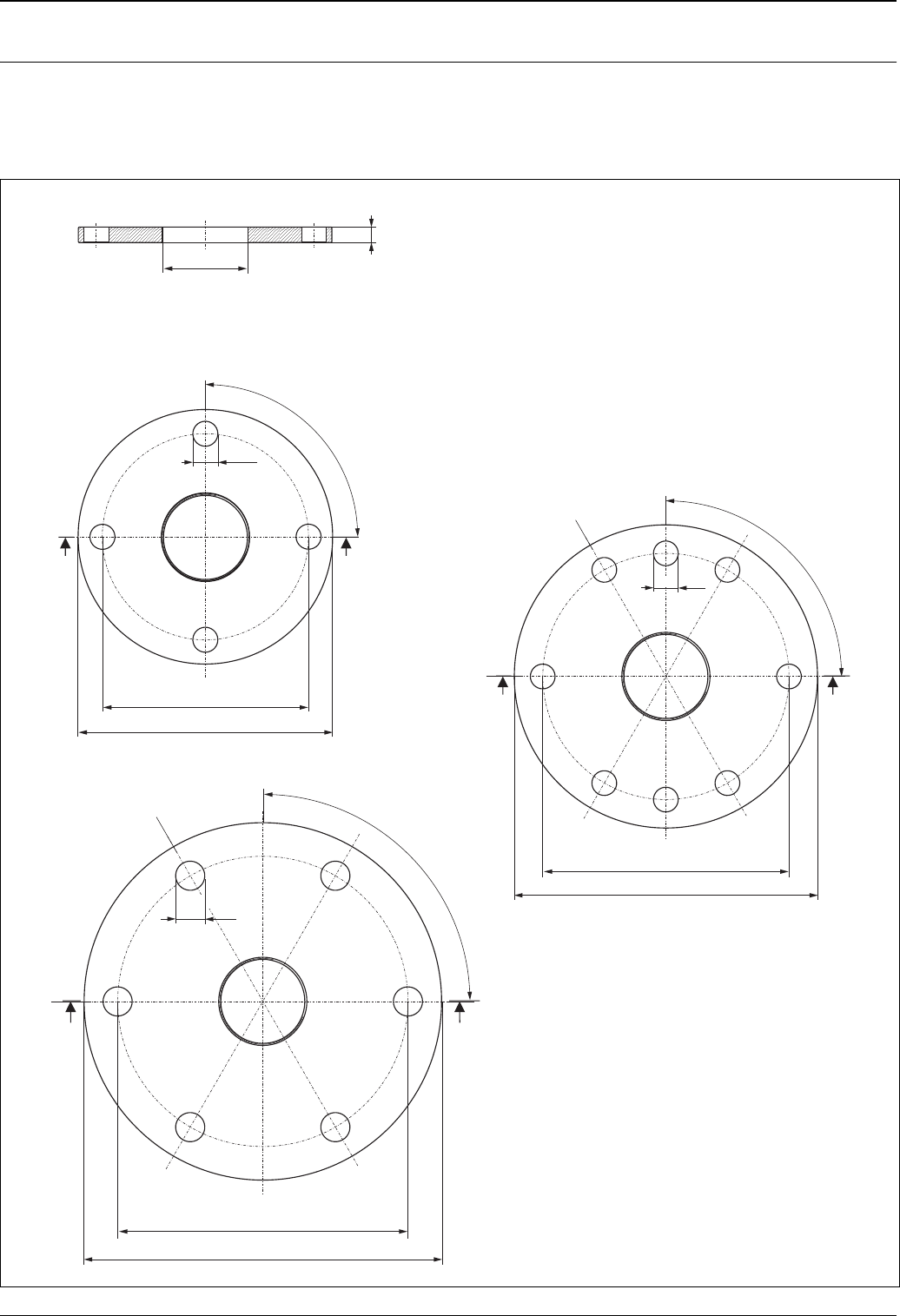
Endress+Hauser UNI flange Installation hints
The number of bolts has sometimes been reduced. The bolt-holes have been enlarged for adaption of
dimensions, therefore, the flange needs to be properly aligned to the counterflange before the bolts are
tightened.
L00-FMR540xx-06-00-00-en-002
4x90°
280
Ø 23
A
A
A
A
A
A
A-A
8
340
405
4x90°
6x90°
Ø 26
Ø 29
240
294,5
358
Endress+Hauser UNI flange DN150
compatible with:
- DN150 PN10/16,
- ANSI 6" 150 lbs,
- JIS 10K 150A
Endress+Hauser UNI flange DN200
compatible with:
- DN200 PN10/16,
- ANSI 8" 150 lbs,
- JIS 10K 200A
Endress+Hauser UNI flange DN250
compatible with:
- DN250 PN10/16,
- ANSI 10" 150 lbs,
- JIS 10K 250A
material: 316L
M80.3
Micropilot S FMR540
24 Endress+Hauser
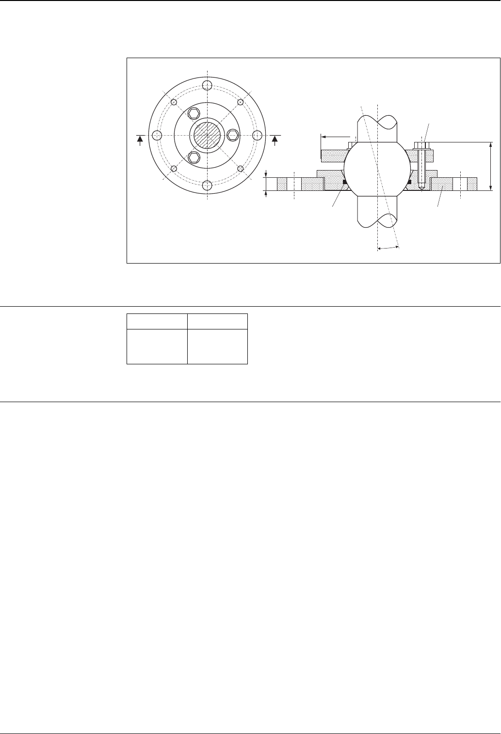
Top target positioner (Sensor alignment) with Endress+Hauser UNI flange
L00-FMR540xx-06-00-00-en-003
Please, also see sensor alignment tool →ä32.
Weight
Please, refer to ordering information →ä30.
Material • Housing T12: aluminium, seawater-resistant, chromated, powder-coated
• Sight window: glass
A
A-A
A
±15°
8
40
Ø 85
Endress+Hauser UNI flange
DN200/DN250
clamping screw
3 x M8 shifty at 120°
Viton seal
Micropilot S FMR540
Weight T12
housing
Approx. 6 kg
+
weight of flange
Micropilot S FMR540
Endress+Hauser 25
Human interface
Operation concept The display of the process value and the configuration of the Micropilot is done locally by means of a large 4-
line alphanumeric display with plain text information. The guided menu system with integrated help texts
ensures a quick, safe and easy commissioning.
Display and operation is selectable from one out of six languages (English, German, French, Italian, Dutch,
Spanish and Japanese). During the first start-up, the instrument explicitly asks for the desired unit / language.
To access the display the cover of the electronic compartment may be removed even in hazardous area (Ex ia,
IS).
Remote commissioning, including documentation of the measuring point and in-depth analysis functions, is
supported via the ToF Tool, the graphical operating software for Endress+Hauser time-of-flight systems.
Access to the electronics can be prevented by means of a custody locking switch that locks the device settings.
The custody locking switch can be sealed for custody transfer applications.
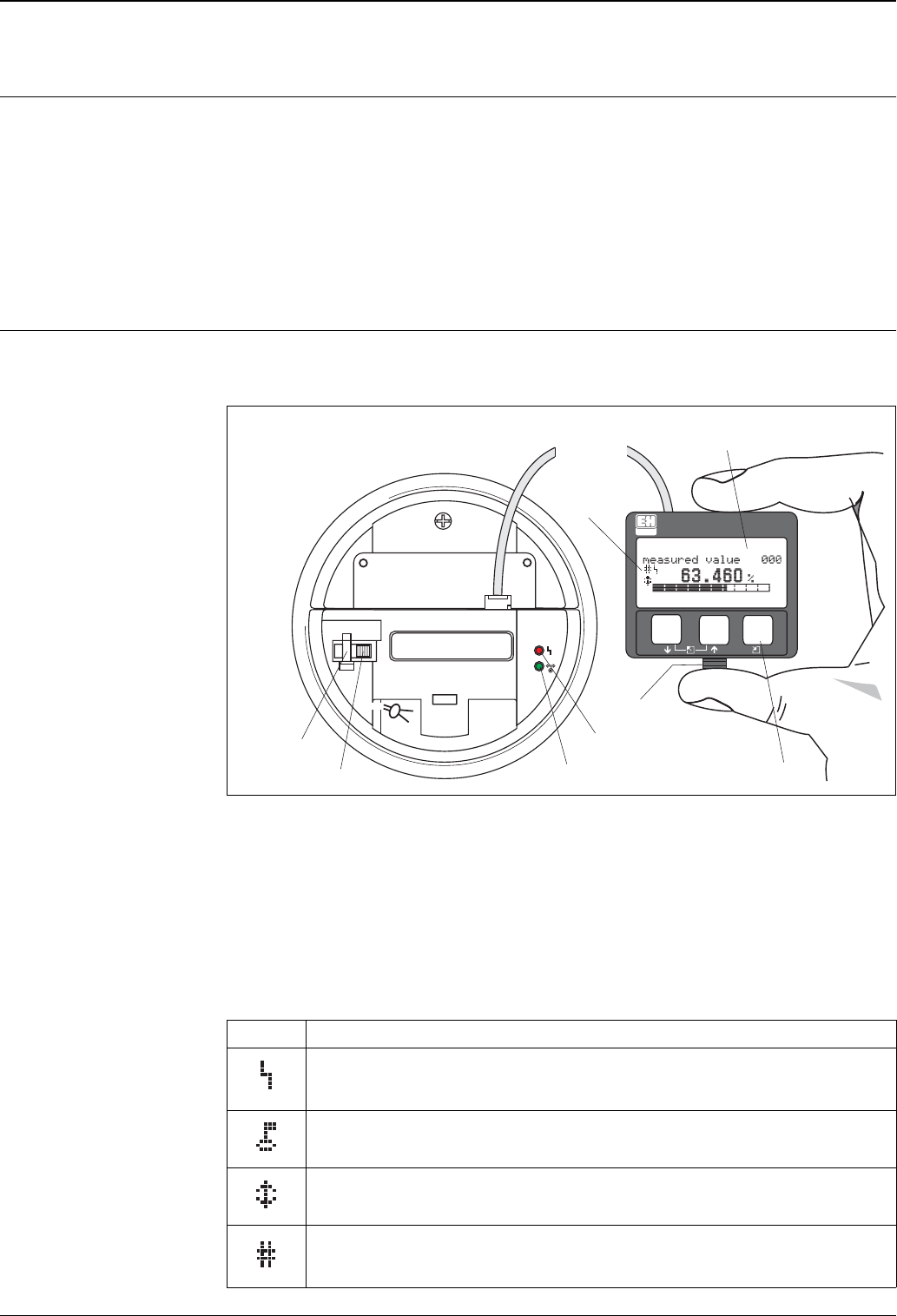
Display elements Liquid crystal display (LCD):
Four lines with 20 characters each. Display contrast adjustable through key combination.
L00-FMR53xxx-07-00-00-en-001
Note!
To access the display, it is possible to open the cover of the electronics compartment even in an explosion
hazardous area.
The VU331 LCD display can be removed to ease operation by simply pressing the snap-fit (see graphic above).
It is connected to the device by means of a 500 mm cable.
Display symbols
The following table describes the symbols that appear on the liquid crystal display:
Symbols Meaning
ALARM_SYMBOL
This alarm symbol appears when the instrument is in an alarm state. If the symbol flashes, this indicates a
warning.
LOCK_SYMBOL
This lock symbol appears when the instrument is locked,i.e. if no input is possible.
COM_SYMBOL
This communication symbol appears when a data transmission via e.g. HART is in progress.
Calibration to regulatory standards disturbed
If the instrument is not locked or it cannot guarantee the calibration to regulatory standards, the situation
will be indicated on the display via the symbol.
ENDRESS + HAUSER
E
+
–
3 keys
snap-fit
red LED
green LED
sealing pin
custody locking switch
LCD
(liquid crystal display)
symbols

Micropilot S FMR540
26 Endress+Hauser
Light emitting diods (LEDs):
There is a green and a red LED besides the Liquid Crystal Display.
Operating elements The operating elements are located inside the housing and are accessible for operation by opening the lid of the
housing.
Function of the keys
LED Meaning
red LED continuously on Alarm
red LED flashes Warning
red LED off No alarm
green LED continuously on Operation
Green LED flashes Communication with external device
Key(s) Meaning
O or VNavigate upwards in the selection list
Edit numeric value within a function
S or VNavigate downwards in the selection list
Edit numeric value within a function
X or ZNavigate to the left within a function group
FNavigate to the right within a function group
O and F
or
S and FContrast settings of the LCD
O and S and F
Hardware lock / unlock
After a hardware lock, an operation of the instrument via display or communication is not
possible!
The hardware can only be unlocked via the display. An unlock parameter must be entered
to do so.
Micropilot S FMR540
Endress+Hauser 27
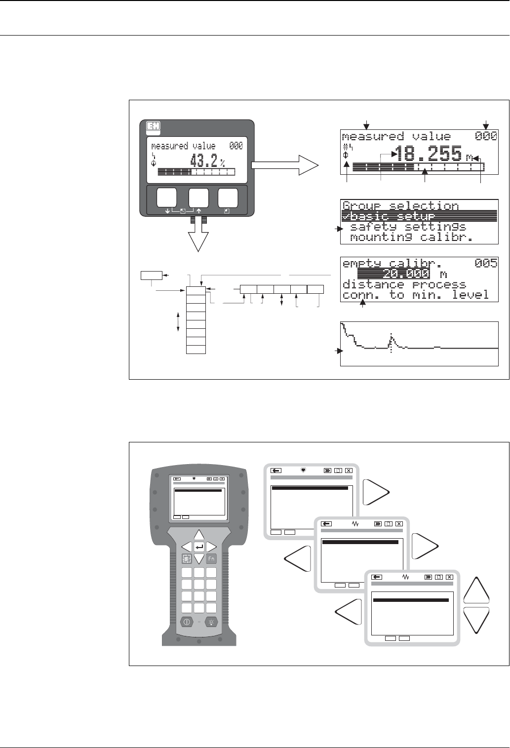
On-site configuration Operation with VU331
The LC-Display VU331 allows configuration via 3 keys directly at the instrument. All device functions can be
set through a menu system. The menu consists of function groups and functions. Within a function, application
parameters can be read or adjusted. The user is guided through a complete configuration procedure.
L00-FMRxxxxx-07-00-00-en-002
Operation with handheld unit Field Communicator DXR375
All device functions can be adjusted via a menu operation with the handheld unit DXR375.
L00-FMR2xxxx-07-00-00-yy-007
Note!
Further information on the handheld unit is given in the respective operating manual included in the transport
bag of the DXR375.
XX
X
X
S
S
O
OFF
F
F
HOME
FG00 F000 F001 F002 F003 F004 ...
FG01
FG02
FG03
FG04
FG05
FG06
FG07
...
+21dB 09C
10.002.305m
0.00
ENDRESS + HAUSER
E
+
–
Headline Position indicator
Main value
Unit
Symbol
Selection list
Function groups -> Functions
Help text
Envelope
curve
Bargraph
1
# % &
Copy
G H I
P Q R S
, ( ) ‘
A B C
Paste
Page
On
Page
Up
DeleteBksp
Insert
J K L
T U V
_ < >
D E F
Hot Key
+ Hot Key
M N O
W X Y Z
+ * /
4
7
.
2
5
8
0
375
FIELD COMMUNICATOR
3
6
9
-
96
FMR231: LIC0001
ONLINE
1 GROUP SELECT
2 PV 8.7 m
HELP SAVE
dsdmdm
df das.
asdas fa
asas la.
Page
On
Page
Up
Bksp
Delete
Delete
FMR231: LIC0001
ONLINE
1 GROUP SELECTION
2 PV 8.7 m
HELP SAVE
dsdmdm
df das.
asdas fa
asas la.
FMR231: LIC0001
GROUP SELECTION
HOMESAVE
dsdmdm
df das.
asdas fa
asas la.
H
FMR231: LIC0001
HOMESAVE
dsdmdm
df das.
asdas fa
asas la.
H
Bksp
1 BASIC SETUP
2 SAFETY SETTINGS
BASIC SETUP
1 MEASURED VALUE
4 PROCESS COND.
5 EMPTY CALIBR.
3 MEDIUM PROPERTY
4 EXTENDED CALIB.
5 OUTPUT
3 LINEARISATION
2 TANK SHAPE
Micropilot S FMR540
28 Endress+Hauser
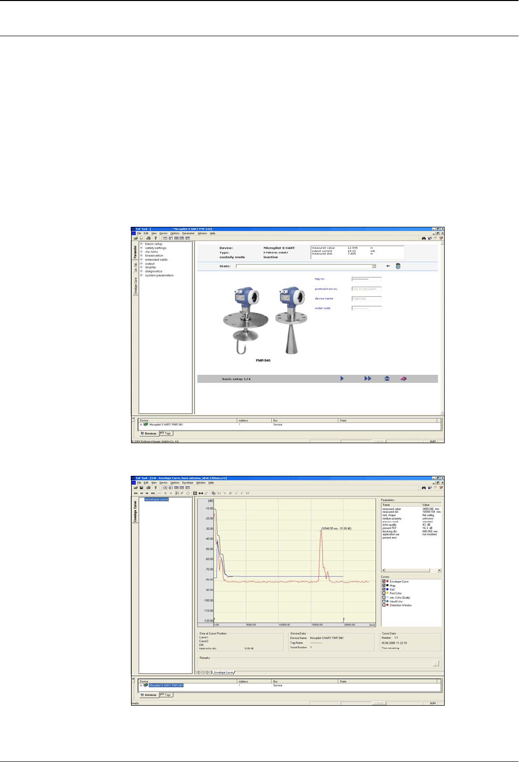
Remote configuration The Micropilot S can be remotely operated via HART. On-site adjustments are also possible.
Operation with ToF Tool
The ToF Tool is a graphical operation software for instruments from Endress+Hauser that operate based on the
time-of-flight principle. It is used to support commissioning, securing of data, signal analysis and
documentation of the instruments. It is compatible with the following operating systems: WinNT4.0, Win2000
and WinXP.
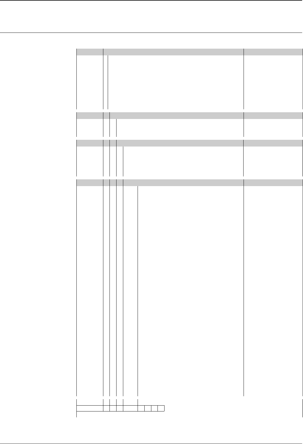
The ToF Tool supports the following functions:
• Online configuration of transmitters
• Signal analysis via envelope curve
• Linearisation table (create, edit, import and export)
• Loading and saving of instrument data (Upload/Download)
• Documentation of measuring point
Menu-guided commissioning:
Signal analysis via envelope curve:
Connection options:
• HART with Commubox FXA191, FXA195
• Service-interface with adapter FXA193 (RS232C) or FXA291 and ToF Adapter FXA291 (USB)
L00-FMR540xx-20-00-00-en-001
L00-FMR540xx-20-00-00-de-001

Micropilot S FMR540
Endress+Hauser 29
Operation with FieldCare
FieldCare is Endress+Hauser's FDT based Plant Asset Management Tool. It can configure all intelligent field
devices in your plant and supports you in managing them. By using status information, it also provides a simple
but effective means of checking their health.
• Operates all Endress+Hauser devices
• Operates all third-party actuators, I/O systems and sensors supporting the FDT standard
• Ensures full functionality for all devices with DTMs
• Offers generic profile operation for any third-party fieldbus device that does not have a vendor DTM
Certificates and approvals
CE approval The measuring system meets the legal requirements of the EC-guidelines. Endress+Hauser confirms the
instrument passing the required tests by attaching the CE-mark.
Ex approval See "Ordering information" on →ä30.
External standards and
guidelines
To conception and development for Micropilot S have been followed the external standards and guidelines:
EN 60529
Protection class of housing (IP-code)
EN 61010
Safety regulations for electrical devices for measurement, control, regulation and laboratory use.
EN 61326
Emissions (equipment class B), compatibility (appendix A – industrial area)
NAMUR
Standards committee for measurement and control in the chemical industry
API (American Petroleum Institute)
Particulary "Manual of Petroleum Measurement Standards"
OIML R85 (Organisation Internationale de Métrologie Légale)
Type approvals for custody
transfer approvals
All aspects of OIML R85 are fulfilled
RF approvals R&TTE 1999/5/EG, FCC CRF 47, part 15
Any changes or modifications not expressly approved by the party responsible for compliance could void the user's
authority to operate the equipment.
Micropilot S FMR540
30 Endress+Hauser
Ordering information
Micropilot S FMR540 This overview does not mark options which are mutually exclusive.
10 Approval: Baisc weight
A Non-hazardous area
6.0 Kg
(T12 Transmitter housing)
1 ATEX II 1/2G EEx ia IIC T6
6 *ATEX II 1/2G EEx ia IIC T6, WHG (in preparation)
G *ATEX II 3G EEx nA II T6 (in preparation)
S *FM IS Cl.I Div.1 Gr.A-D (in preparation)
U *CSA IS Cl.I Div.1 Gr.A-D (in preparation)
K *TIIS Ex ia IIC T3 (in preparation)
L *TIIS Ex ia IIC T6 (in preparation)
Y Special version
20 Antenna; Seal:
5 100mm/4" horn; FKM Viton GLT 0.6 Kg
6 200mm/8" Parabolic, FKM Viton GLT 0.3 Kg
9 Special version
30 Antenna Extension: Additional weigth
1 W/o 1.8 Kg
2150mm/6" 2.0 Kg
3 250mm/10" 2.3 Kg
4 450mm/18" 2.9 Kg
9 Special version
40 Process connection: Additional weight
– EN-Flanges –
CQJ DN100 PN10/16 B1, 316L 4.9 Kg
CWJ DN150 PN10/16 B1, 316L 10.6 Kg
– ASME-Flanges –
APJ 4" 150lbs RF, 316/316L 7.0 Kg
AVJ 6" 150lbs RF, 316/316L 11.3 Kg
flange B16.5
– JIS-Flanges –
KH5 10K 100 RF, 316L 4.5 Kg
flange JIS
KV5 10K 150 RF, 316L 10.1 Kg
flange JIS
– Miscellaneous –
XVJ UNI flange DN150/6"/150, 316L 3.4 Kg
Max PN1/14.5lbs/1K, suitable for
DN150 PN10/16, 6" 150lbs, 10K 150
X3J UNI flange DN200/8"/200, 316L 4.4 Kg
Max PN1/14.5lbs/1K, suitable for
DN200 PN10/16, 8" 150lbs, 10K 200
X5J UNI flange DN250/10"/250, 316L 5.4 Kg
Max PN1/14.5lbs/1K, suitable for
DN250 PN10/16, 10" 150lbs, 10K 250
XDJ align. device., UNI 6"/DN150/150, 316L 5.8 Kg
max 14.5lbs/PN1/1K, suitable for
6" 150lbs / DN150 PN16 / 10K 150
XEJ align. device., UNI 8"/DN200/200, 316L 4.9 Kg
max 14.5lbs/PN1/1K, suitable for
8" 150lbs / DN200 PN16 / 10K 200
XFJ align. device., UNI 10"/DN250/250, 316L 5.9 Kg
max 14.5lbs/PN1/1K, suitable for
10" 150lbs / DN250 PN16 / 10K 250
YY9 Special version
FMR540- Product designation (part 1)
Micropilot S FMR540
Endress+Hauser 31
Ordering structure
(continued)
50 Output; Operation:
A 4-20mA HART; 4-line display VU331, envelope curve display on site
Y Special version
60 Housing:
C T12 Alu, coated IP68 NEMA4X, separate connection compartment
Y Special version
70 Cable entry:
1 Thread M20
2Gland M20
3Thread G1/2
4 Thread NPT1/2
9 Special version
80 Weight + Measure Approval:
A NMi + PTB (<1mm) weight & measure approval
F NMi witnessed initial verificat. (<1mm)
Type approval
G *PTB witnessed initial verificat. (<1mm) (in preparation)
Type approval
R Not selected; Inventory control
Version (3mm)
Y Special version
90 Additional Option:
A Basic version
Y Special version
FMR540- Complete product designation
Micropilot S FMR540
32 Endress+Hauser
Accessories
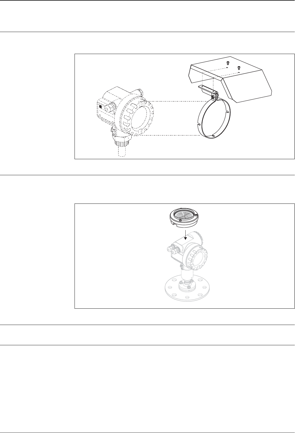
Weather protection cover A Weather protection cover made of stainless steel is recommended for outdoor mounting (order code:
543199-0001). The shipment includes the protective cover and tension clamp.
L00-FMR2xxxx-00-00-06-en-001
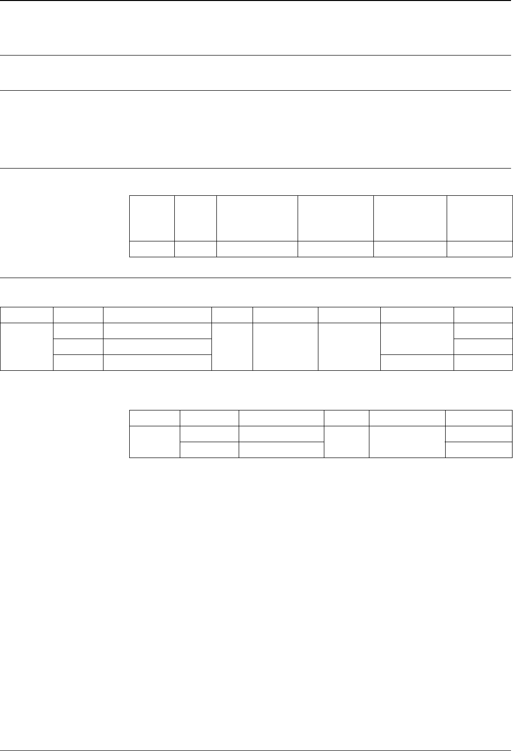
Sensor alignment tool for
Target Positioner (alignment
device option) only
A sensor alignment tool is recommended to be used at the time of installation for FMR540 with Top Target
Positioner (alignment device feature). Order code: 52026756
For instructions see document KA267F/00/A2.
L00-FMR540xx-00-00-00-en-001
Commubox FXA191 HART For intrinsically safe communication with ToF Tool/FieldCare via the RS232C interface. For details refer to
TI237F/00/en.
Commubox FXA195 HART For intrinsically safe communication with ToF Tool/FieldCare via the USB interface. For details refer to
TI404F/00/en.
ENDRESS+HAUSER
MICROPILOT II
ENDRESS+HAUSER
MICROPILOT II
IP 65
Order Code:
Ser.-No.:
Order Code:
Ser.-No.:
Messbereich
Measuring range
Messbereich
Measuring range
U 16...36V DC
4...20 mA
U 16...36 V DC
4...20 mA
max.20 m
max. 20 m
Made in Germany Maulburg
Made in Germany Maulburg
T>
70°C :
At >85°C
T >70°C :
At >85°C
F12 / F23 / T12 housing
5°
4°
3°
2°
1°
0°

Micropilot S FMR540
Endress+Hauser 33
Commubox FXA291 The Commubox FXA291 connects Endress+Hauser field instruments with CDI interface (= Endress+Hauser
Common Data Interface) to the USB interface of a personal computer or a notebook. For details refer to
TI405C/07/en.
Note!
For the following Endress+Hauser instruments you need the "ToF Adapter FXA291" as an additional accessory:
• Cerabar S PMC71, PMP7x
• Deltabar S PMD7x, FMD7x
• Deltapilot S FMB70
• Gammapilot M FMG60
• Levelflex M FMP4x
• Micropilot FMR130/FMR131
• Micropilot M FMR2xx
• Micropilot S FMR53x, FMR540
• Prosonic FMU860/861/862
• Prosonic M FMU4x
• Tank Side Monitor NRF590 (with additional adapter cable)
ToF Adapter FXA291 The ToF Adapter FXA291 connects the Commubox FXA291 via the USB interface of a personal computer or
a notebook to the following Endress+Hauser instruments:
• Cerabar S PMC71, PMP7x
• Deltabar S PMD7x, FMD7x
• Deltapilot S FMB70
• Gammapilot M FMG60
• Levelflex M FMP4x
• Micropilot FMR130/FMR131
• Micropilot M FMR2xx
• Micropilot S FMR53x, FMR540
• Prosonic FMU860/861/862
• Prosonic M FMU4x
• Tank Side Monitor NRF590 (with additional adapter cable)
For details refer to KA271F/00/a2.
Micropilot S FMR540
34 Endress+Hauser
Documentation
Fields of activities Level Measurement
Limit detection and continuous level measurement in liquids and bulk solids, FA001/F/00/en.
Technical Information Fieldgate FXA320, FXA520
Technical Information for Fieldgate FXA320/520, TI369F/00/en.
Tank Side Monitor NRF590
Technical Information for Tank Side Monitor NRF590, TI374F/00/en.
Operating Instructions Operating instructions for FMR540:
Certificates Safety instructions (XA) and certificates (ZE) for FMR540:
Control Drawings (ZD) for FMR540:
Instrument Output Communication Operating
Instructions
Description of
Instrument
Functions
Brief Operating
Instructions
(in the
Instrument)
FMR540 A HART BA326F/00/en BA341F/00/en KA255F/00/A2
Instrument Certificate Explosion protection Output Communication PTB 00 ATEX XA WHG
FMR540
1 ATEX II 1/2 G EEx ia IIC T6
A HART 2067X XA338F/00/a3
6 ATEX II 1/2 G EEx ia, WHG in preparation
G ATEX II 3 G EEx nA II T6 in preparation
Instrument Certificate Explosion protection Output Communication ZD
FMR540 SFM IS
AHART
ZD194F/00/en
U CSA IS ZD196F/00/en

Micropilot S FMR540
Endress+Hauser 35
Patents
This product may be protected by at least one of the following patents.
Further patents are pending.
• US 5,387,918 i EP 0 535 196
• US 5,689,265 i EP 0 626 063
• US 5,659,321
• US 5,614,911 i EP 0 670 048
• US 5,594,449 i EP 0 676 037
• US 6,047,598
• US 5,880,698
• US 5,926,152
• US 5,969,666
• US 5,948,979
• US 6,054,946
• US 6,087,978
• US 6,014,100

International Head Quarter
Endress+Hauser
GmbH+Co. KG
Instruments International
Colmarer Str. 6
79576 Weil am Rhein
Deutschland
Tel. +49 76 21 9 75 02
Fax +49 76 21 9 75 34 5
www.endress.com
info@ii.endress.com
TI412F/00/en/09.06
FM+SGML 6.0 ProMoDo