Endress and Hauser and Co FMR25X Level Radar Transmitter User Manual Levelflex M
Endress and Hauser GmbH and Co Level Radar Transmitter Levelflex M
Users Manual
BA284F/00/en/08.04
Nr. 52025089
Valid as of software version:
V 01.01.00 (amplifier)
V 01.01.00 (communication)
Operating Instructions
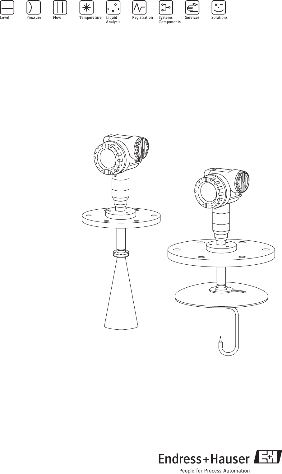
Micropilot M FMR250
Level-Radar
6

Micropilot M FMR250 with HART/4...20 mA
2Endress + Hauser
Brief overview
For quick and simple commissioning:
Safety Instructions
Explanation of the warning symbols
You can find special instructions at the appropriate position in the chapter in
question. The positions are indicated with the icons Warning #, Caution " and
Note !.
→Page 6 ff.
Æ
Installation
The steps for installing the device and installation conditions (e.g. dimensions)
can be found here.
→Page 11 ff.
Æ
Wiring
The device is virtually completely wired on delivery. →Page 25 ff.
Æ
Display and Operating Elements
An overview of the position of the display and operating elements can be found
here.
→Page 33 ff.
Æ
Commissioning
In the "Commissioning" section, you learn how to switch on the device and
check the functioning.
→Page 41 ff.
Æ
Commissioning via Display VU 331
In the "Operating" section, you become familiar with the operating elements
and the various setting options.
Basic Setup with the VU331.
→Page 31 ff.
→Page 44 ff.
Æ
Commissioning via Operating Software ToF Tool
Basic Setup with the ToF Tool.
Additional information on the operation of the ToF Tool can be found in the
operating instructions BA224F/00, which can be found on the enclosed
CD-ROM.
→Page 59 ff.
Æ
Fault Tracking / Trouble Shooting
If faults occur during operation, use the checklist to localise the cause.
Here you can find measures you can take yourself to take remedial action
against the fault.
→Page 66 ff.
Æ
Index
You can find important terms and keywords on the individual sections here.
Use the keyword index to find quickly and efficiently the information you need.
→Page 92 ff.
Micropilot M FMR250 with HART/4...20 mA
Endress + Hauser 3
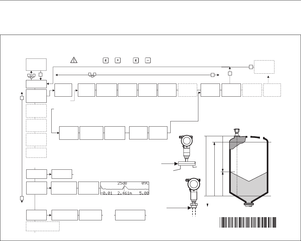
Brief operating instructions
L00-FMR250xx-19-00-00-en-020
!Note!
This operating manual explains the installation and initial start-up for the level transmitter. All
functions that are required for a typical measuring task are taken into account here. In addition, the
Micropilot M provides many other functions that are not included in this operating manual, such as
optimising the measuring point and converting the measured values.
An overview of all device functions can be found on Page 86.
The operating manual BA291F/00/en "Description of the instrument functions for Micropilot M"
provides an extensive description of all device functions, which can be found on the enclosed
CD-ROM.
E
+
-
+
E
+
-
E
E
-
… …
… …
KA 235F/00/a2/08.04
52025245
… …
20 mA
100%
4mA
0%
D
L
F
E
52025245
Micropilot M FMR250 - Brief operating instructions
- dome
ceiling
- horizontal
cyl.
- bypass
…
- unknown
- metal silo
- concrete
silo
- bin / bunker
…
- liquid
- solid
- unknown
- DC: <1.9
- DC: 1.9 … 4
- DC: 4 … 10
- DC: >10
- standard
- calm
surface
- add.
agitator
…
input E
(see sketch)
input E
(see sketch)
input F
(see sketch)
input F
(see sketch)
only for
bypass +
stilling well
- ok
- too small
- too big
- unknown
- manual
displayed
(see sketch)
D and L are confirm
or specify
range
suggestion
000
measured
value
Group
selection
00
basic
setup
01
safety
settings
0C
system parameter
09
display
0E
envelope
curve
04
linearisation
05
extended
calibr.
06
output
092
language
0A
diagnostics
0A0
present error
002
tank
shape
002
tank
shape
00A
vessel /
silo
004
process
cond.
005
empty
calibr.
005
empty
calibr.
006
full
calibr.
006
full
calibr.
007
pipe
diameter
008
dist./
meas value
051
check
distance
003
medium
cond.
00B
medium
cond.
00C
proscess
cond.
052
range of
mapping
053
start
mapping
008
dist./
meas value
- envel. curve
- incl. FAC
- incl. cust. map
- single curve
- cyclic
= 100: unlocked
100: locked≠
0E1
plot settings
0E2
recording
curve
0A1
previous error
0A4
unlock parameter
HART
}
Contrast: +or +
- unknown
- DC: 1.6...1.9
- DC: 1.9 …2.5
- DC: 2.5 …4
...
- standard
- fast change
- slow change
- test: no filter
flange:
reference point of
measurement
flange:
reference point of
measurement
threaded
connection
1 ½” (R 1
:
reference point of
measurement
BSPT ½”)
or 1½ NPT
001
media
type

Micropilot M FMR250 with HART/4...20 mA
4Endress + Hauser

Micropilot M FMR250 with HART/4...20 mA Table of contents
Endress + Hauser 5
Table of contents
1 Safety instructions . . . . . . . . . . . . . . . . 6
1.1 Designated use . . . . . . . . . . . . . . . . . . . . . . . . . . . . 6
1.2 Installation, commissioning and operation . . . . . . . . 6
1.3 Operational safety . . . . . . . . . . . . . . . . . . . . . . . . . . 6
1.4 Notes on safety conventions and symbols . . . . . . . . . 7
2 Identification . . . . . . . . . . . . . . . . . . . . 8
2.1 Device designation . . . . . . . . . . . . . . . . . . . . . . . . . 8
2.2 Scope of delivery . . . . . . . . . . . . . . . . . . . . . . . . . . 10
2.3 Certificates and approvals . . . . . . . . . . . . . . . . . . . 10
2.4 Registered trademarks . . . . . . . . . . . . . . . . . . . . . . 10
3 Installation . . . . . . . . . . . . . . . . . . . . . 11
3.1 Quick installation guide . . . . . . . . . . . . . . . . . . . . . 11
3.2 Incoming acceptance, transport, storage . . . . . . . . . 11
3.3 Installation conditions . . . . . . . . . . . . . . . . . . . . . . 12
3.4 Installation instructions . . . . . . . . . . . . . . . . . . . . . 19
3.5 Post-installation check . . . . . . . . . . . . . . . . . . . . . . 24
4 Wiring . . . . . . . . . . . . . . . . . . . . . . . . 25
4.1 Quick wiring guide . . . . . . . . . . . . . . . . . . . . . . . . 25
4.2 Connecting the measuring unit . . . . . . . . . . . . . . . 27
4.3 Recommended connection . . . . . . . . . . . . . . . . . . 30
4.4 Degree of protection . . . . . . . . . . . . . . . . . . . . . . . 30
4.5 Post-connection check . . . . . . . . . . . . . . . . . . . . . . 30
5 Operation . . . . . . . . . . . . . . . . . . . . . . 31
5.1 Quick operation guide . . . . . . . . . . . . . . . . . . . . . . 31
5.2 Display and operating elements . . . . . . . . . . . . . . . 33
5.3 Local operation . . . . . . . . . . . . . . . . . . . . . . . . . . . 35
5.4 Display and acknowledging error messages . . . . . . 38
5.5 HART communication . . . . . . . . . . . . . . . . . . . . . . 39
6 Commissioning. . . . . . . . . . . . . . . . . . 41
6.1 Function check . . . . . . . . . . . . . . . . . . . . . . . . . . . 41
6.2 Switching on the measuring device . . . . . . . . . . . . 41
6.3 Basic Setup . . . . . . . . . . . . . . . . . . . . . . . . . . . . . . 42
6.4 Basic Setup with the VU331 . . . . . . . . . . . . . . . . . 44
6.5 Basic Setup with the ToF Tool . . . . . . . . . . . . . . . . 59
7 Maintenance. . . . . . . . . . . . . . . . . . . . 63
8 Accessories. . . . . . . . . . . . . . . . . . . . . 64
9 Trouble-shooting . . . . . . . . . . . . . . . . 66
9.1 Trouble-shooting instructions . . . . . . . . . . . . . . . . 66
9.2 System error messages . . . . . . . . . . . . . . . . . . . . . . 67
9.3 Application errors in liquids . . . . . . . . . . . . . . . . . . 69
9.4 Application errors in solids . . . . . . . . . . . . . . . . . . . 71
9.5 Orientation of the Micropilot . . . . . . . . . . . . . . . . . 73
9.6 Spare parts . . . . . . . . . . . . . . . . . . . . . . . . . . . . . . 75
9.7 Return . . . . . . . . . . . . . . . . . . . . . . . . . . . . . . . . . . 81
9.8 Disposal . . . . . . . . . . . . . . . . . . . . . . . . . . . . . . . . . 81
9.9 Software history . . . . . . . . . . . . . . . . . . . . . . . . . . . 81
9.10 Contact addresses of Endress+Hauser . . . . . . . . . . . 81
10 Technical data . . . . . . . . . . . . . . . . . . . 82
10.1 Additional technical data . . . . . . . . . . . . . . . . . . . . 82
11 Appendix. . . . . . . . . . . . . . . . . . . . . . . 86
11.1 Operating menu HART (display modul), ToF Tool . 86
11.2 Description of functions . . . . . . . . . . . . . . . . . . . . . 88
11.3 Function and system design . . . . . . . . . . . . . . . . . . 89
Index . . . . . . . . . . . . . . . . . . . . . . . . . . . . . . 92

Safety instructions Micropilot M FMR250 with HART/4...20 mA
6Endress + Hauser
1 Safety instructions
1.1 Designated use
The Micropilot M FMR250 is a compact level radar for the continuous, contactless measurement of
predominantly solids. The device can also be freely mounted outside closed metal vessels because
of its operating frequency of about 26 GHz and a maximum radiated pulsed energy of 1mW
(average power output 1 µW). Operation is completely harmless to humans and animals.
1.2 Installation, commissioning and operation
The Micropilot M has been designed to operate safely in accordance with current technical, safety
and EU standards. If installed incorrectly or used for applications for which it is not intended,
however, it is possible that application-related dangers may arise, e.g. product overflow due to
incorrect installation or calibration. For this reason, the instrument must be installed, connected,
operated and maintained according to the instructions in this manual: personnel must be authorised
and suitably qualified. The manual must have been read and understood, and the instructions
followed. Modifications and repairs to the device are permissible only when they are expressly
approved in the manual.
1.3 Operational safety
1.3.1 Hazardous areas
Measuring systems for use in hazardous environments are accompanied by separate "Ex
documentation", which is an integral part of this Operating Manual. Strict compliance with the
installation instructions and ratings as stated in this supplementary documentation is mandatory.
• Ensure that all personnel are suitably qualified.
• Observe the specifications in the certificate as well as national and local standards and regulations.
1.3.2 FCC approval
This device complies with part 15 of the FCC Rules. Operation is subject to the following two
conditions: (1) This device may not cause harmful interference, and (2) this device must accept any
interference received, including interference that may cause
undesired operation.
"Caution!
Changes or modifications not expressly approved by the part responsible for
compliance could void the user’s authority to operate the equipment.

Micropilot M FMR250 with HART/4...20 mA Safety instructions
Endress + Hauser 7
1.4 Notes on safety conventions and symbols
In order to highlight safety-relevant or alternative operating procedures in the manual, the following
conventions have been used, each indicated by a corresponding symbol in the margin.
Safety conventions
#Warning!
A warning highlights actions or procedures which, if not performed correctly, will lead to personal
injury, a safety hazard or destruction of the instrument
"Caution!
Caution highlights actions or procedures which, if not performed correctly, may lead to personal
injury or incorrect functioning of the instrument
!Note!
A note highlights actions or procedures which, if not performed correctly, may indirectly affect
operation or may lead to an instrument response which is not planned
Explosion protection
0Device certified for use in explosion hazardous area
If the device has this symbol embossed on its name plate it can be installed in an explosion hazardous
area
-Explosion hazardous area
Symbol used in drawings to indicate explosion hazardous areas. Devices located in and wiring
entering areas with the designation “explosion hazardous areas” must conform with the stated type
of protection.
.Safe area (non-explosion hazardous area)
Symbol used in drawings to indicate, if necessary, non-explosion hazardous areas. Devices located in
safe areas still require a certificate if their outputs run into explosion hazardous areas
Electrical symbols
%Direct voltage
A terminal to which or from which a direct current or voltage may be applied or supplied
&Alternating voltage
A terminal to which or from which an alternating (sine-wave) current or voltage may be applied or
supplied
)Grounded terminal
A grounded terminal, which as far as the operator is concerned, is already grounded by means of an
earth grounding system
*Protective grounding (earth) terminal
A terminal which must be connected to earth ground prior to making any other connection to the
equipment
+Equipotential connection (earth bonding)
A connection made to the plant grounding system which may be of type e.g. neutral star or
equipotential line according to national or company practice
Temperature resistance of the connection cables
States, that the connection calbes must be resistant to a temperature of at least 85 °C.
t >85°C
Identification Micropilot M FMR250 with HART/4...20 mA
8Endress + Hauser
2 Identification
2.1 Device designation
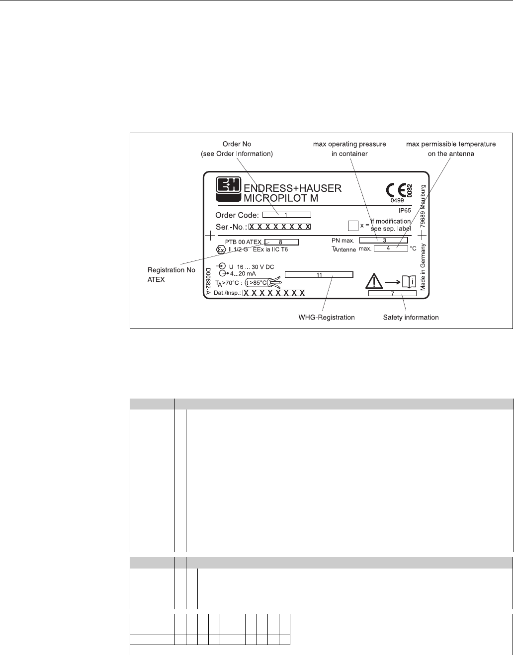
2.1.1 Nameplate
The following technical data are given on the instrument nameplate:
L00-FMR2xxxx-18-00-00-en-001
Fig. 1: Information on the nameplate of the Micropilot M (example)
2.1.2 Ordering structure
Ordering structure Micropilot M FMR250
10 Approval:
A Non-hazardous area
1 ATEX II 1/2G EEx ia IIC T6
4 ATEX II 1/2G EEx d [ia] IIC T6
G ATEX II 3G EEx nA II T6
B ATEX II 1/2GD EEx ia IIC T6, Alu blind cover
C ATEX II 1/2G EEx ia IIC T6, ATEX II 1/3D
D ATEX II 1/2D, Alu blind cover
E ATEX II 1/3D
S FM IS-Cl.I/II/III Div.1 Gr.A-G
T FM XP-Cl.I/II/III Div.1 Gr.A-G
N CSA General Purpose
U CSA IS-Cl.I/II/III Div.1 Gr.A-G
V CSA XP-Cl.I/II/III Div.1 Gr.A-G
YSpecial version
20 Antenna:
4 Horn 80mm/3"
5 Horn 100mm/4"
6 Parabolic 200mm/8"
9 Special version
FMR250- Product designation (part 1)
Micropilot M FMR250 with HART/4...20 mA Identification
Endress + Hauser 9
Ordering structure Micropilot M FMR250 (continued)
30 Antenna seal; Temperature:
E FKM Viton GLT; -40...200°C/-40...392 °F
Y Special version
40 Antenna extension:
1Not selected
2 250mm/10"
3 450mm/18"
9Special version
50 Process connection:
– Threaded boss –
GGJ Thread DIN2999 R1-1/2, 316L
GNJ Thread ANSI NPT1-1/2, 316L
– Universal-Flanges –
X3J UNI flange DN200/8"/200A, 316L
max PN1/14.5LBS/1K, compatible DN200 PN10/16, 8" 150LBS, 10K 200A
XCJ Top target pos., UNI DN100/4"/100A, 316L
max PN1/14.5LBS/1K, compatible DN100 PN10/16, 4" 150LBS, 10K 100A
XEJ Top target pos., UNI DN200/8"/200A, 316L
max PN1/14.5LBS/1K, compatible DN200 PN10/16, 8" 150LBS, 10K 200A
– EN-Flanges –
CMJ DN80 PN10/16 B1, 316L
CQJ DN100 PN10/16 B1, 316L
– ANSI-Flanges –
ALJ 3" 150LBS RF, 316/316L
APJ 4" 150LBS RF, 316/316L
– JIS-Flanges –
KLJ 10K 80A RF, 316L
KPJ 10K 100A RF, 316L
YY9 Special version
60 Output; Operation:
A 4-20mA HART; 4-line display VU331, envelope curve display on site
B 4-20mA HART; w/o display, via communication
K 4-20mA HART; prepared for FHX40, remote display (Accessory)
Y Special version
70 Housing:
A F12 Alu, coated IP65 NEMA4X
B F23 316L IP65 NEMA4X
C T12 Alu, coated IP65 NEMA4X, separate connection compartment
D T12 Alu, coated IP65 NEMA4X + OVP, separate connection compartment,
OVP = overvoltage protection
Y Special version
80 Cable entry:
2Gland M20
3Thread G1/2
4Thread NPT1/2
9Special version
90 Additional option:
K Air purge connection G1/4
M Air purge connection NPT1/4
YSpecial version
FMR250- Complete product designation

Identification Micropilot M FMR250 with HART/4...20 mA
10 Endress + Hauser
2.2 Scope of delivery
"Caution!
It is essential to follow the instructions concerning the unpacking, transport and storage of
measuring instruments given in the chapter "Incoming acceptance, transport, storage" on Page 11!
The scope of delivery consists of:
• Assembled instrument
• 2 ToF Tool - FieldTool® Package CD-ROMs
– CD 1: ToF Tool - FieldTool® Program
Program including Device Descriptions (device drivers) and documentation for all
Endress+Hauser devices wich are operable using ToF Tool
– CD 2: ToF Tool - FieldTool® Utilities
Utility program (e.g. Adobe Acrobat Reader, MS Internet Explorer)
• Accessories (→Chap. 8)
Accompanying documentation:
• Short manual (basic setup/troubleshooting): housed in the instrument
• Operating manual (this manual)
• Approval documentation: if this is not included in the operating manual.
!Note!
The operating manual "Description of Instrument Functions" you can be found on the enclosed CR-
ROM.
2.3 Certificates and approvals
CE mark, declaration of conformity
The instrument is designed to meet state-of-the-art safety requirements, has been tested and left the
factory in a condition in which it is safe to operate. The instrument complies with the applicable
standards and regulations and thus complies with the statutory requirements of the EG directives.
Endress+Hauser confirms the successful testing of the instrument by affixing to it the CE mark.
2.4 Registered trademarks
KALREZ®, VITON®, TEFLON®
Registered trademark of the company, E.I. Du Pont de Nemours & Co., Wilmington, USA
TRI-CLAMP®
Registered trademark of the company, Ladish & Co., Inc., Kenosha, USA
HART®
Registered trademark of HART Communication Foundation, Austin, USA
ToF®
Registered trademark of the company Endress+Hauser GmbH+Co. KG, Maulburg, Germany
PulseMaster®
Registered trademark of the company Endress+Hauser GmbH+Co. KG, Maulburg, Germany
PhaseMaster®
Registered trademark of the company Endress+Hauser GmbH+Co. KG, Maulburg, Germany
Micropilot M FMR250 with HART/4...20 mA Installation
Endress + Hauser 11
3 Installation
3.1 Quick installation guide
L00-FMR250xx-17-00-00-en-011
3.2 Incoming acceptance, transport, storage
3.2.1 Incoming acceptance
Check the packing and contents for any signs of damage.
Check the shipment, make sure nothing is missing and that the scope of supply matches your order.
3.2.2 Transport
"Caution!
Follow the safety instructions and transport conditions for instruments of more than
18 kg.
Do not lift the measuring instrument by its housing in order to transport it.
3.2.3 Storage
Pack the measuring instrument so that is protected against impacts for storage and transport. The
original packing material provides the optimum protection for this.
The permissible storage temperature is -40 °C…+80 °C.
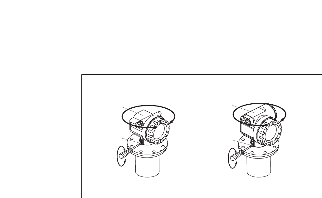
DN80…200
ANSI 3…8”
33
11
22
#
90°
90°
90°
90°
90°
90°
90°
90°
9
90°
90°
F12/F23 housing T12 housing
Turn housing
At mounting adjust the marking at the instrument flange!
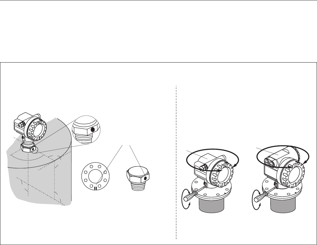
Installation in vessel (free space):
Mark on process connector facing the nearest vessel wall!
The housing can be turned 350° in order to simplify access to the
display and the terminal compartment
Allen key 4 mm / 0.1"
1½” BSPT (R 1½”),
or
1½ NPT
mark at instrument flange
or threaded boss
Note!
At version with top target positioner, the marker is at the housing adapter
(opposite the air purge connection).
Installation Micropilot M FMR250 with HART/4...20 mA
12 Endress + Hauser
3.3 Installation conditions
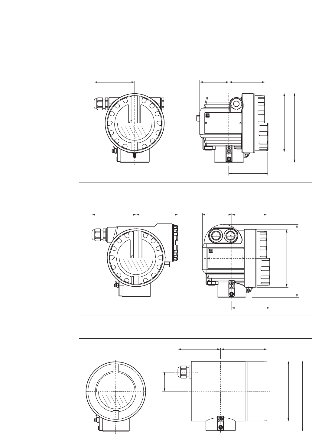
3.3.1 Dimensions
Housing dimensions
L00-F12xxxx-06-00-00-en-001
L00-T12xxxx-06-00-00-en-001
L00-F23xxxx-06-00-00-en-001
ENDRESS+HAUSER
65 78
max. 110
85
150
Ø 129
(Aluminium)
F12 housing
ENDRESS+HAUSER
78
85
65
162
max. 100 94
Ø 129
(Aluminium)
T12 housing
max. 94 104
Ø 129
150
40
(316L)
F23 housing
Micropilot M FMR250 with HART/4...20 mA Installation
Endress + Hauser 13
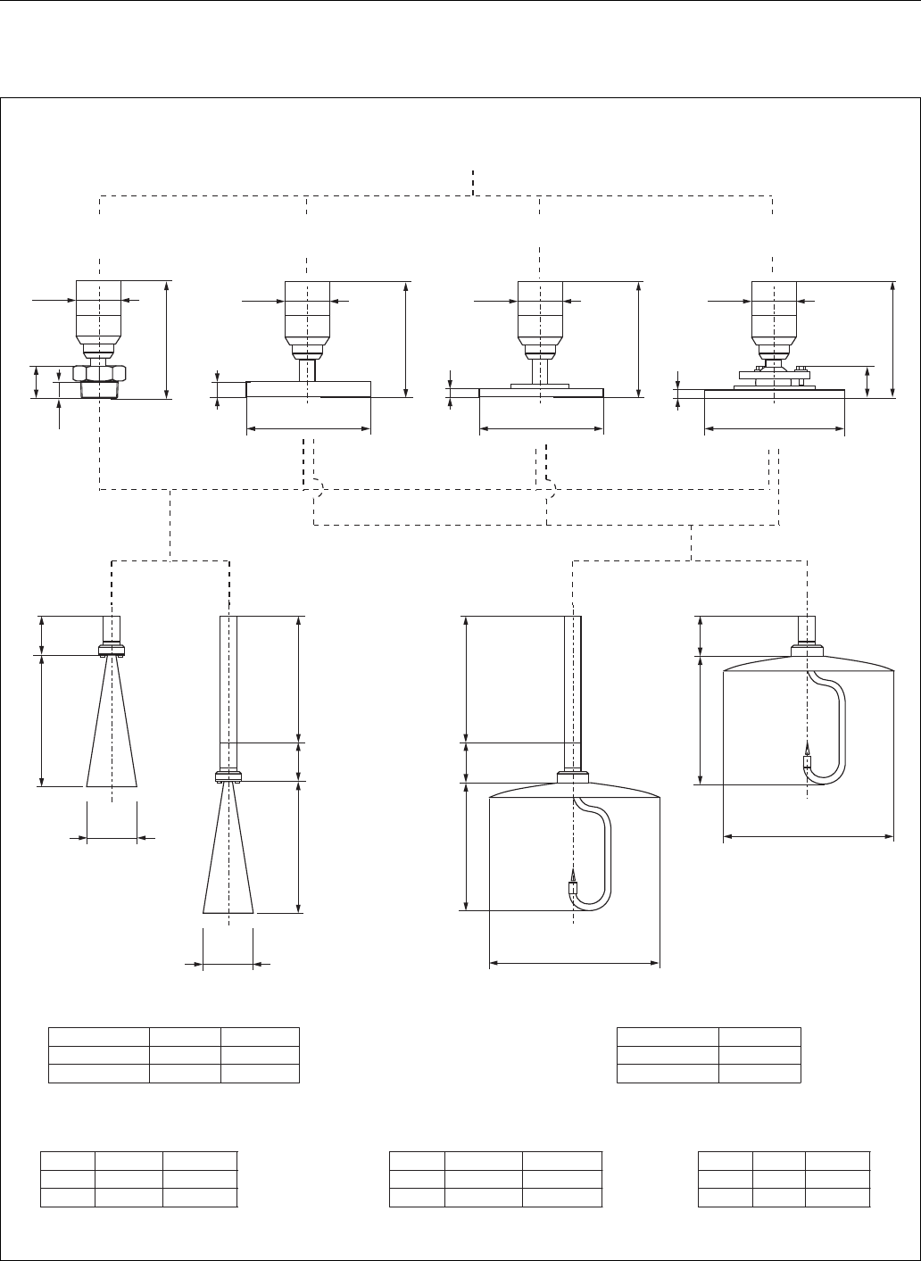
Micropilot M FMR250 - process connection, type of antenna
L00-FMR250xx-06-00-00-en-005
L
L
L
L
50
50
135
40
135
135
135
50
50
Ød
ØdØd
Ød
250/450
250/450
75
211
80mm/3” 200mm/8”
95 197
282 195
100mm/4”
b [mm] b [mm]b [mm]
DN 80 DN 803”
20 1823.9
200 185190.5
L [mm] L [mm]
d [mm] d [mm]
D [mm] D [mm]D [mm]
220 210228.6
20 1823.9
DN 100 DN 1004”
Ø D Ø 340 Ø 225 (DN100)
340 (DN200)Ø
43
b
8
8
23
Ø60
Ø60
Ø60
Ø60
Parabolic antennaHorn antenna
for 10K
Flange
Flange to JIS B2210
for 150 lbs
Flange
Flange to ANSI B16.5
for PN10/16
Antenna size Antenna size
Horn antenna Parabolic antenna
Flange
Flange to EN 1092-1 (agreeable to DIN 2527)
F12 / T12 / F23 housing
Threaded connection
BSPT (R 1 ½”)
or 1 ½ NPT
1 ½” Flange DN80…100
or equivalent
E+H UNI flange DN 200 Alignment unit with
E+H UNI flange DN 100/200
Installation Micropilot M FMR250 with HART/4...20 mA
14 Endress + Hauser
E+H UNI flange
The number of bolts has sometimes been reduced. The bolt-holes have been enlarged for adaption
of dimensions, therefore, the flange needs to be properly aligned to the counterflange before the
bolts are tightened.
L00-FMR250xx-06-00-00-en-006
Top target positioner with E+H UNI flange
L00-FMR250xx-06-00-00-en-007
175
4x90°
4x90°
225
Ø 19
Ø 23
A
A
A
A
A-A
8
340
4x90°
6x60°
Ø 26
Ø 26
E+H UNI flange DN100
compatible with:
- DN100 PN10/16,
- ANSI 4" 150 lbs,
- JIS 10K 100A
E+H UNI flange DN200
compatible with:
- DN200 PN10/16,
- ANSI 8" 150 lbs,
- JIS 10K 200A
material: 316L
M80x1.5
185.5
294.5
A
A-A
A
±15°
8
40
Ø 85
E+H UNI flange
DN100/DN200
clamping screw
3 x M8 shifty at 120°
Viton seal
Micropilot M FMR250 with HART/4...20 mA Installation
Endress + Hauser 15
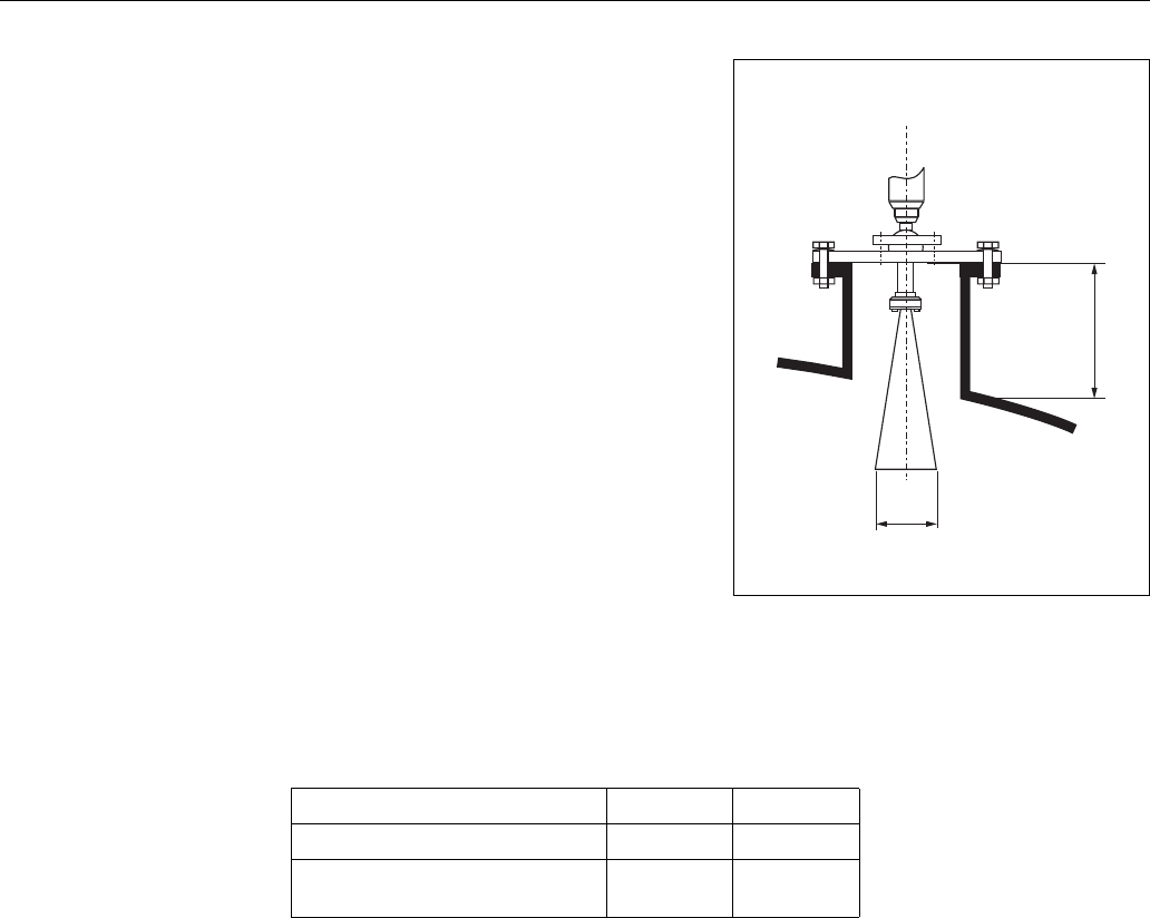
3.3.2 Engineering hints
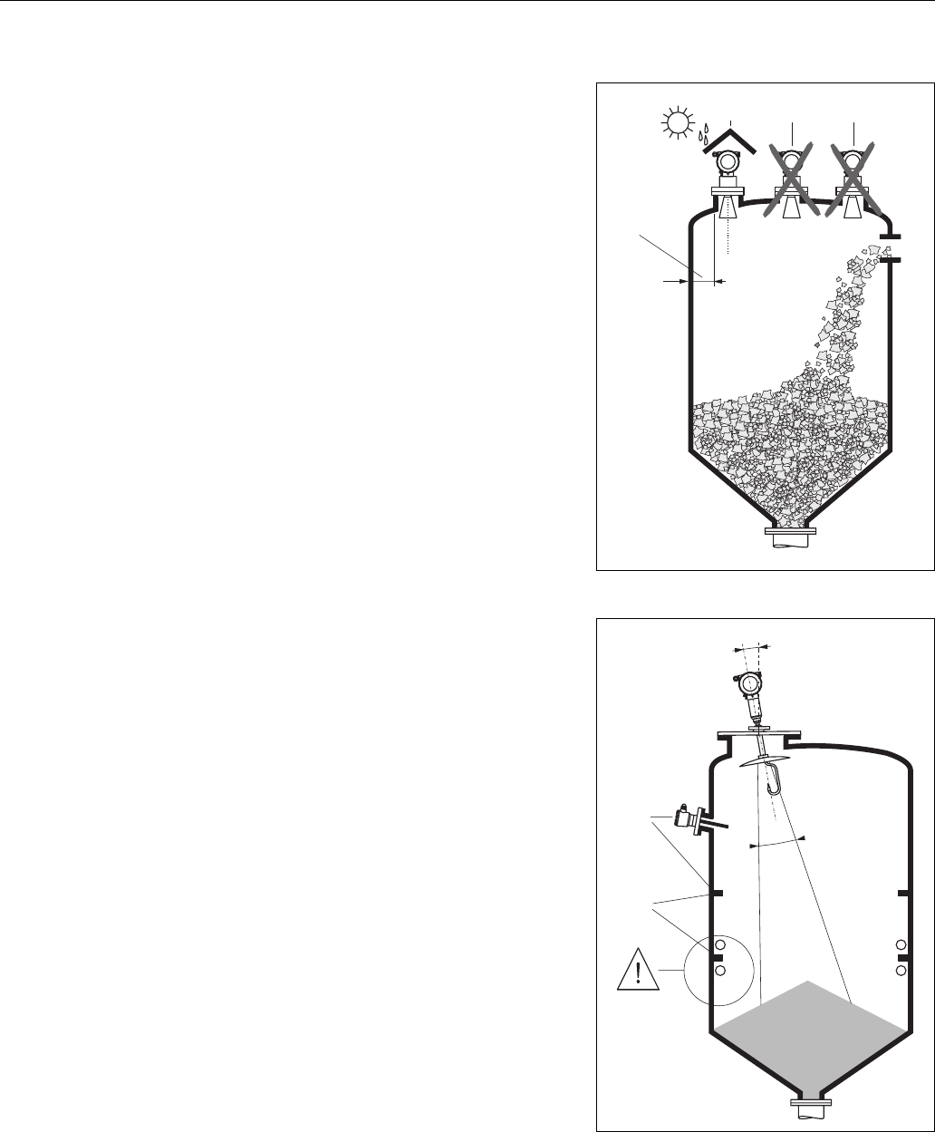
Orientation
• Recommended distance (1) wall – outer
edge of nozzle: ~1/6 of vessel diameter.
However, the device should not, under any
circumstances, be mounted less than 20 cm/
8“ from the vessel wall.
• Not in the centre (3), interference can cause
signal loss.
• Not above the fill stream (4).
• It is recommended to use a weather
protection cover (2) in order to protect the
transmitter from direct sun or rain. Assembly
and disassembly is simply done by means of a
tension clamp (→Chap. 8 on Page 64).
• In extremely dusty applications, the
integrated air purge connection can prevent
clogging of the antenna.
L00-FMR250xx-17-00-00-xx-003
1
234
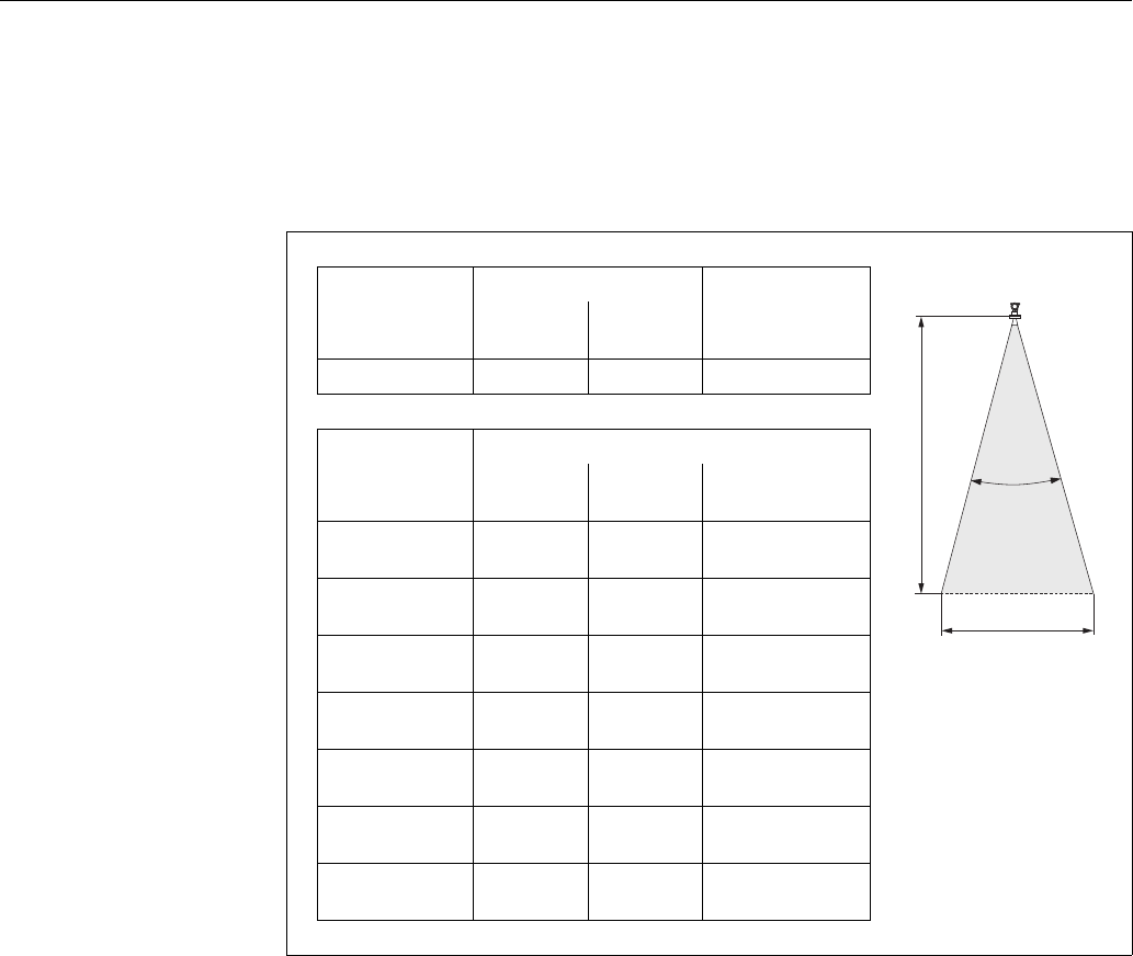
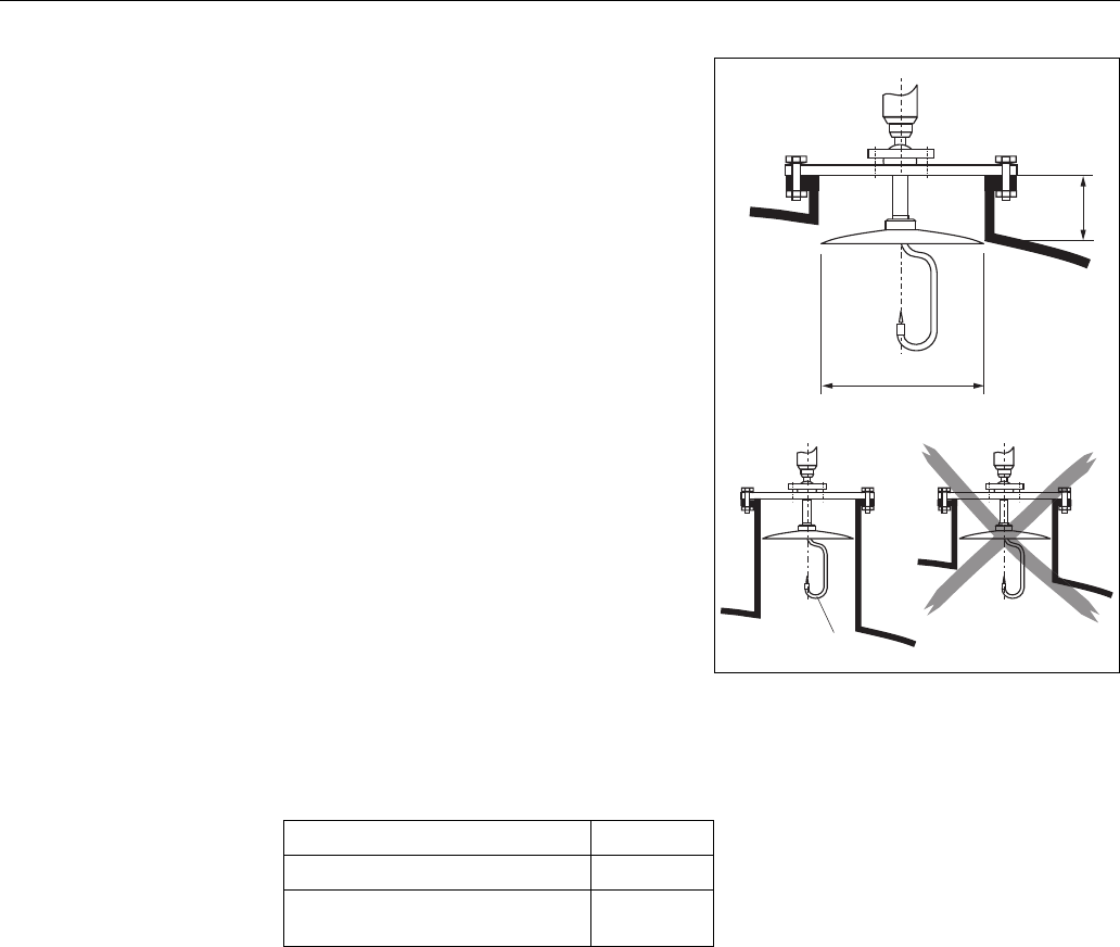
Vessel installations
• Avoid any installations (1), like limit switches,
struts, etc., inside the signal beam (refer to
beam angle see "Beam angle" on Page 16).
• Symmetrical installations (2), i.e. reinforcing
rings, heating coils, etc., can also interfere
with the measurement.
Optimization options
• Antenna size: the bigger the antenna, the
smaller the beam angle, the less interference
echoes.
• Mapping: the measurement can be optimized
by means of electronic suppression of
interference echoes.
• Antenna alignment: refer to "Optimum
mounting position"
• In devices with top target positioner, the
sensor can be optimally aimed within the
vessel and/or interference reflections can be
avoided.
The max. angle β is ±15°.
Please contact Endress+Hauser for further
information.
L00-FMR250xx-17-00-00-xx-002
1
2
Installation Micropilot M FMR250 with HART/4...20 mA
16 Endress + Hauser
Beam angle
The beam angle is defined as the angle a where the energy density of the radar waves reaches half
the value of the maximum energy density (3dB-width). Microwaves are also emitted outside the
signal beam and can be reflected off interfering installations. Beam diameter W as function of
antenna type (beam angle α) and measuring distance D:
Antenna size
FMR250
Horn antenna Parabolic antenna
L00-FMR2xxxx-14-00-06-de-027
80 mm
3"
100 mm
4"
200 mm
8"
Beam angle α10° 8° 4°
Measuring
distance (D)
Beamwidth diameter (W)
80 mm
3"
100 mm
4"
200 mm
8"
5m / 16 ft 0.87 m /
2.80 ft
0.70 m /
2.24 ft
0.35 m /
1.12 ft
10 m / 32 ft 1.75 m /
5.60 ft
1.40 m /
4.48 ft
0.70 m /
2.23 ft
15 m / 49 ft 2.62 m /
8.57 ft
2.10 m /
6.85 ft
1.05 m /
3.42 ft
20 m / 65 ft 3.50 m /
11.37 ft
2.80 m /
9.09 ft
1.40 m /
4.54 ft
30 m / 98 ft 5.25 m /
17.15 ft
4.20 m /
13.71 ft
2.10 m /
6.84 ft
40 m / 131 ft 7.00 m /
22.92 ft
5.59 m /
18.32 ft
2.79 m /
9.15 ft
50 m / 164 ft 8.75 m /
28.70 ft
6.99 m /
22.94 ft
3.50 m /
11.45 ft
D
W
Micropilot M FMR250 with HART/4...20 mA Installation
Endress + Hauser 17
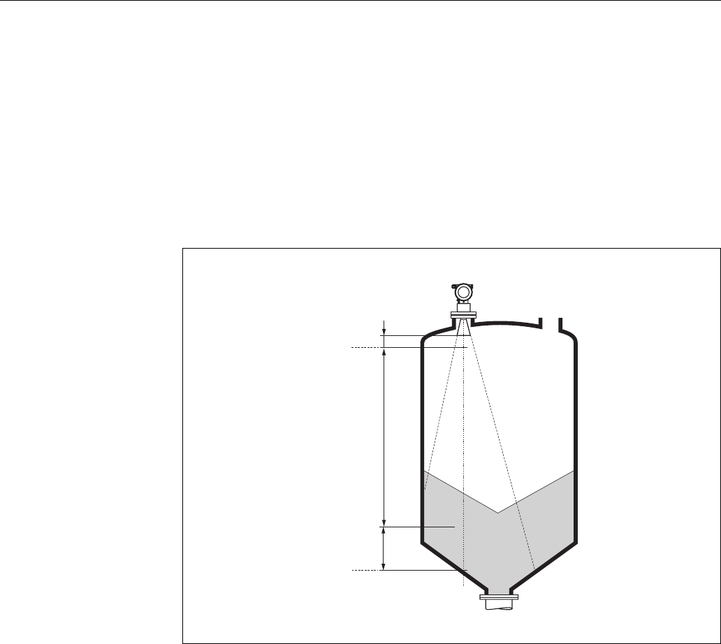
Measuring conditions
• The measuring range begins, where the beam hits the vessel bottom. Particularly with dish
bottoms or conical outlets the level cannot be detected below this point.
• In case of media with a low dielectric constant (groups A and B), the vessel bottom can be visible
through the medium at low levels. In order to guarantee the required accuracy in these cases, it
is recommended to position the zero-point at a distance C =50...150 mm above the vessel bottom
(see Fig.).
• In principle it is possible to measure up to the tip of the antenna with FMR250. However, due to
considerations regarding abrasion and build-up, the end of the measuring range should not be
chosen any closer than A=400 mm (see Fig.) to the tip of the antenna.
• The smallest possible measuring range B=500 mm (see Fig.).
L00-FMR250xx-17-00-00-en-001
100%
0%
B
A
C

Installation Micropilot M FMR250 with HART/4...20 mA
18 Endress + Hauser
Measuring range
The usable measuring range depends on the size of the antenna, the reflectivity of the medium, the
mounting location and eventual interference reflections. The maximum configurable range is 70 m
(229 ft) for Micropilot M FMR250.
To achieve an optimised Signal strength it is recommended to use an antenna with as large as
possible diameter (DN200/8" parabolic antenna, DN100/4" horn).
Reduction of the max. possible measuring range through:
• Media with poor reflection properties (= small DC). For examples refer to table 1.
• Angle of repose.
• Extremely loose surfaces of bulk solids, e.g. bulk solids with low bulk weight for pneumatic filling.
• Build-up, above all of moist products.
Table 1:
The following table describes the media groups and the dielectric constant εr.
The respective lower group applies for very loose or loosened bulk solids.
Media group DC (εr) Examples Signal attenuation
A1.6...1.9
– Plastic granulate
– White lime, special cement
–Sugar
19...16 dB
B1.9...2.5 – Portland cement, plaster 16...13 dB
C2.5...4
–Grain, seeds
–Ground stones
–Sand
13...10 dB
D4...7 – Naturally moist (ground) stones, ores
–Salt 10...7 dB
E>7
– Metallic powder
– Carbon black
–Coal
< 7 dB
Micropilot M FMR250 with HART/4...20 mA Installation
Endress + Hauser 19
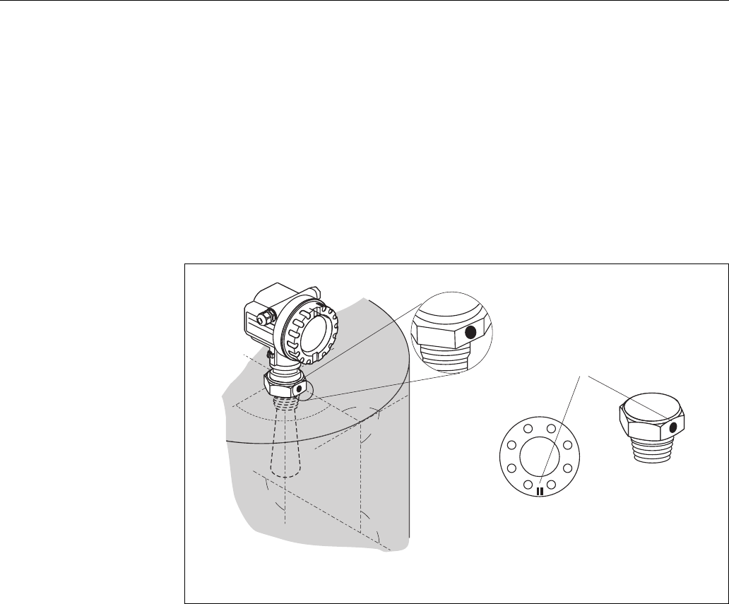
3.4 Installation instructions
3.4.1 Mounting kit
For the mounting , you will require the following tool:
• The tool for flange mounting or
• a key AF60 for threaded boss and
• 4 mm/0.1" Allen wrench for turning the housing.
3.4.2 Installation in vessel (free space)
Optimum mounting position
L00-FMR250xx-17-00-00-en-009
90°
90°
90°
90°
90°
90°
90°
90°
9
DN80…200
ANSI 3…8”
90°
1½” BSPT (R 1½”)
or
1½ NPT
marker at instrument
flange or threaded boss
1)
1)
at version with top target positioner, the marker is at the housing adapter
(opposite the air purge connection)
Installation Micropilot M FMR250 with HART/4...20 mA
20 Endress + Hauser
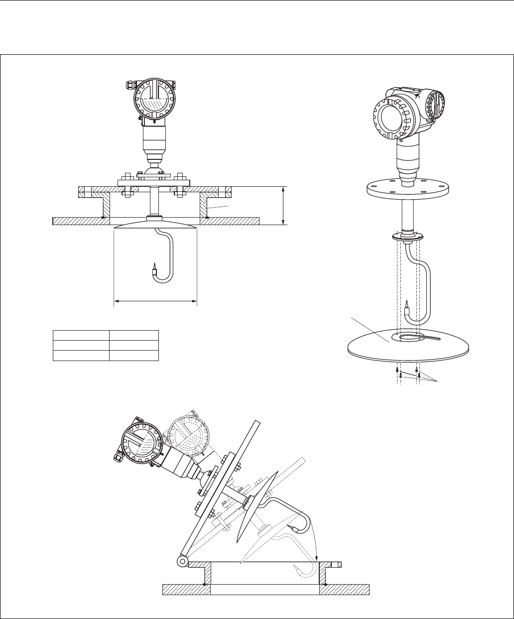
Standard installation FMR250 with horn
antenna
• Observe installation instructions on Page 15.
• Marker is aligned towards vessel wall.
• The marker is always exactly in the middle
between two bolt-holes in the flange.
• After mounting, the housing can be turned
350° in order to simplify access to the display
and the terminal compartment.
• The horn antenna should protrude from the
nozzle. If necessary, choose version with
antenna extension (see Page 13).
If this is not possible for mechanical reasons,
nozzle heights up to 500 mm can be
accepted.
Note!
Please contact Endress+Hauser for application
with higher nozzle.
•Vertical horn antenna.
Ideally, the horn antenna should be installed
vertically.
To avoid interference reflections or for
optimum alignment within the vessel, the
FMR250 with optional top target positioner
can be swiveled by 15° in all directions.
L00-FMR250xx-17-00-00-en-004
H
ØD
Antenna size 80 mm / 3" 100 mm / 4"
D [mm / inch] 75 / 3 95 / 3.7
H [mm / inch]
(without antenna extension) < 260 / < 10.2 < 330 / < 12.9
Micropilot M FMR250 with HART/4...20 mA Installation
Endress + Hauser 21
Standard installation FMR250 with
parabolic antenna
• Observe installation instructions on Page 15.
• Marker is aligned towards vessel wall.
• The marker is always exactly in the middle
between two bolt-holes in the flange.
• After mounting, the housing can be turned
350° in order to simplify access to the display
and the terminal compartment.
• Ideally the parabolic antenna should protrude
from the nozzle (1). If necessary, choose
version with antenna extension (see Page 13).
Particularly when using the top target
positioner, please ensure that the parabolic
reflector is protruding from the nozzle/roof so
as not to inhibit alignment.
Note!
For application with higher nozzle install
parabolic antenna completely in the
nozzle (2), including RF-wave guide (3).
•Vertical parabolic antenna.
Ideally, the parabolic antenna should be
installed vertically.
To avoid interference reflections or for
optimum alignment within the vessel, the
FMR250 with optional top target positioner
can be swiveled by 15° in all directions.
L00-FMR250xx-17-00-00-en-005
H
ØD
1
2
3
Antenna size 200 mm / 8"
D [mm / inch] 197 / 7.75
H [mm / inch]
(without antenna extension) < 50 / < 1.96
Installation Micropilot M FMR250 with HART/4...20 mA
22 Endress + Hauser
Examples for installation with small flange (< parabolic reflector)
L00-FMR250xx-17-00-00-en-007
H
D
D [mm]
200mm/8”
197
< 50
H [mm] 1)
for installation
in nozzle
you can dismantle
the parabolic reflector
4 bolts
standard installation
nozzle
Antenna size
Caution!
At hinged flanges, the length of the antenna
must be taken into account!
1) without antenna extension
Micropilot M FMR250 with HART/4...20 mA Installation
Endress + Hauser 23
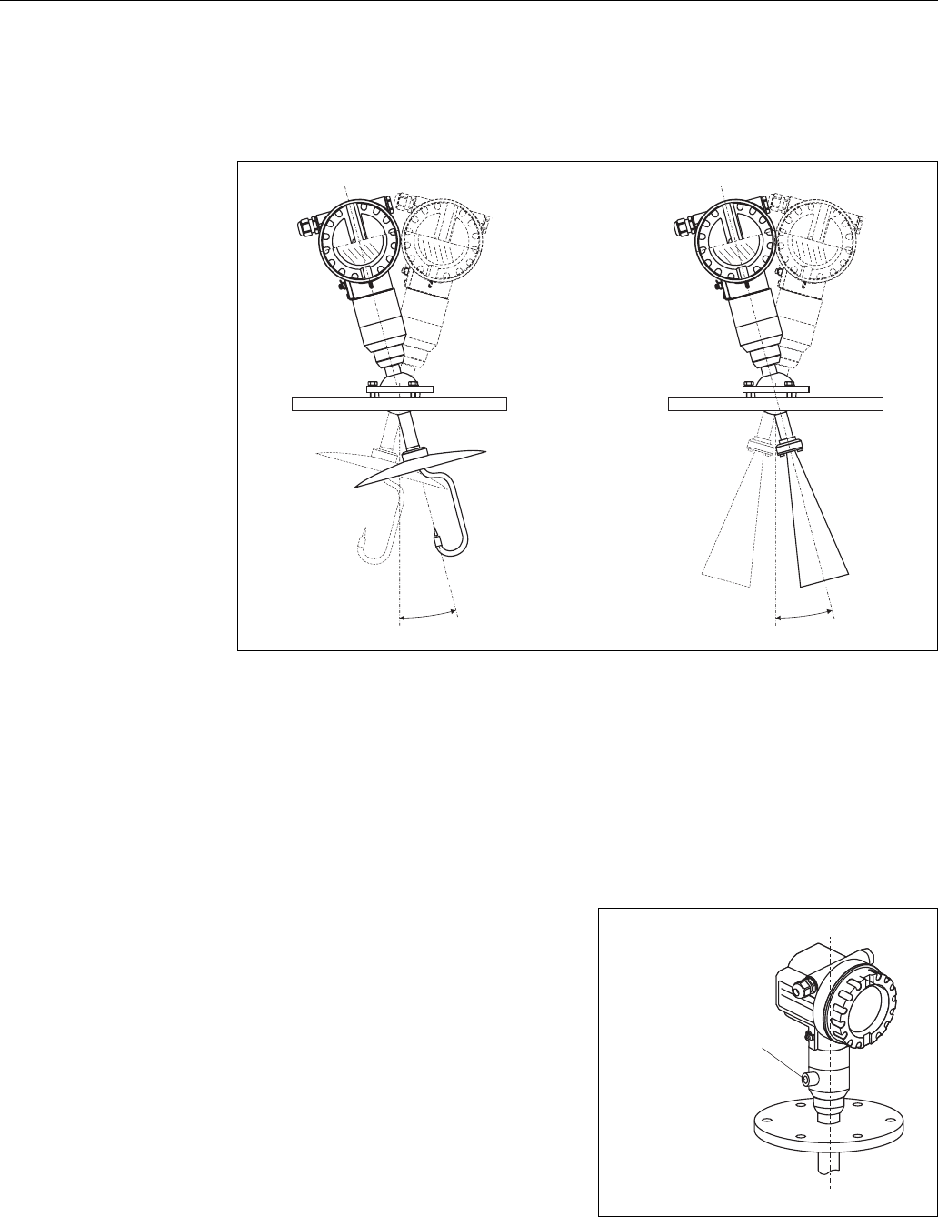
FMR250 with top target positioner
Using top target positioner it is possible to tilt the antenna axis by up to 15° in all directions. The
top target positioner is used for the optimum alignment of the radar beam with the bulk solids
surface.
L00-FMR250xx-17-00-00-de-008
Align antenna axis:
1. Loosen screws.
2. Align antenna axis (here this is possible up to max. ±15° in all directions).
3. Tighten screws.
Integrated air purge connection
±15°
±15°
In extremely dusty applications, the integrated
air purge connection can prevent clogging of the
antenna.
• Permanent operation:
recommended pressure range of the purge air:
1.2...1.5 bar abs.
• Pulsed operation:
max. pressure of purge air: 6 bar abs.
Caution!
Make sure to use dry purge air.
L00-FMR250xx-17-00-00-en-010
air purge connection:
NPT
or
G (max. torque 3.5 Nm)
¼
¼
Installation Micropilot M FMR250 with HART/4...20 mA
24 Endress + Hauser
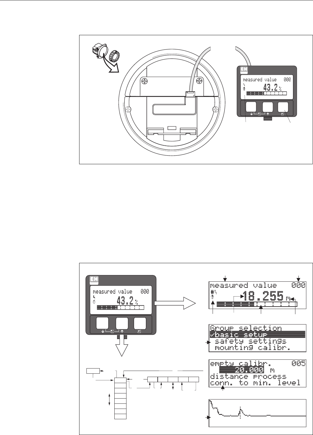
3.4.3 Turn housing
After mounting, the housing can be turned 350° in order to simplify access to the display and the
terminal compartment. Proceed as follows to turn the housing to the required position:
• Undo the fixing screws (1)
• Turn the housing (2) in the required direction
• Tighten up the fixing screws (1)
L00-FMR2xxxx-17-00-00-en-010
3.5 Post-installation check
After the measuring instrument has been installed, perform the following checks:
• Is the measuring instrument damaged (visual check)?
• Does the measuring instrument correspond to the measuring point specifications such as process
temperature/pressure, ambient temperature, measuring range, etc.?
• Is the flange marking correctly aligned? (→Page 11)
• Have the flange screws been tightened up with the respective tightening torque?
• Are the measuring point number and labeling correct (visual check)?
• Is the measuring instrument adequately protected against rain and direct sunlight (→Page 64)?
1
1
22
F12 / F23 housing T12 housing
allen key
4 mm/0.1”
Micropilot M FMR250 with HART/4...20 mA Wiring
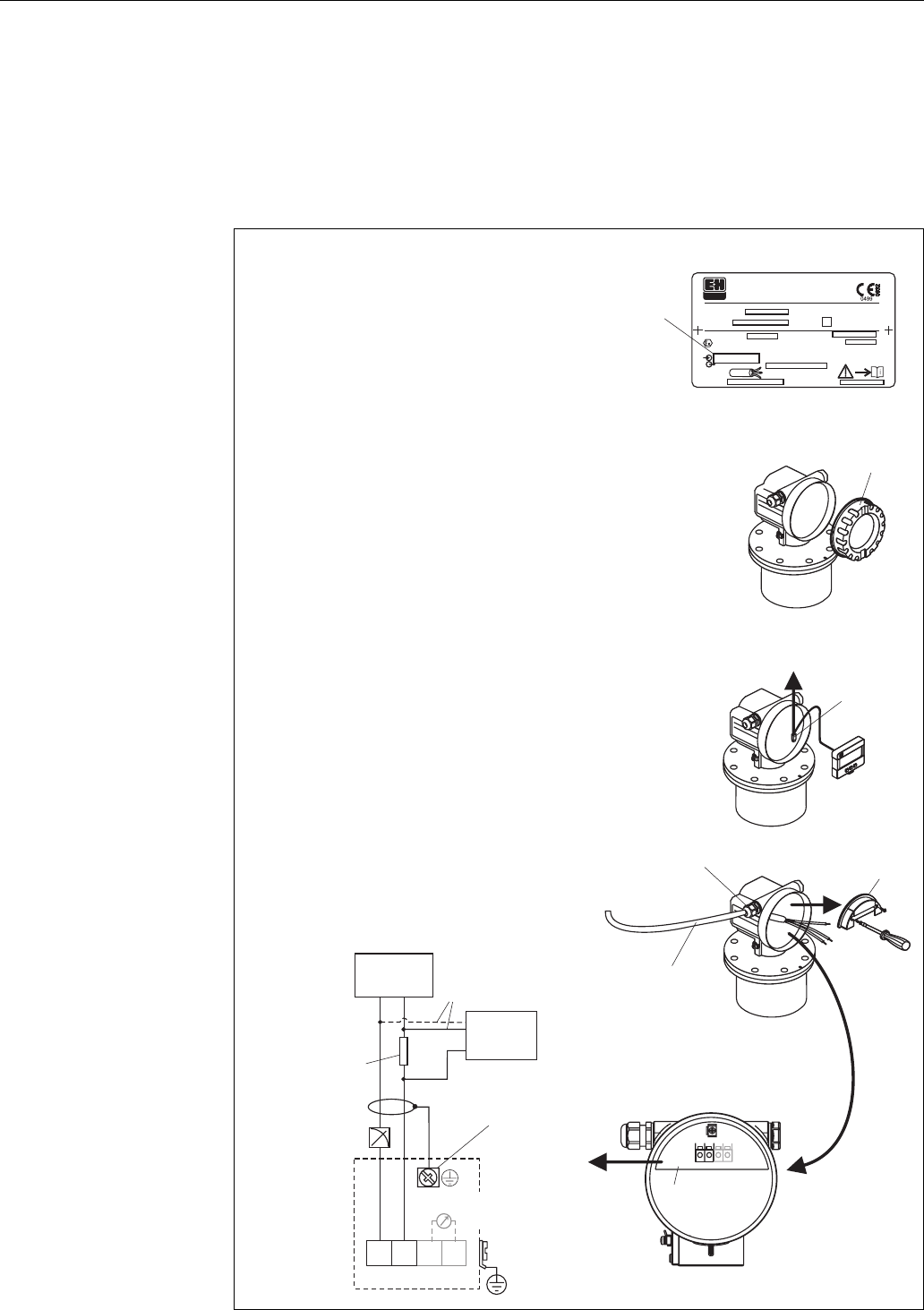
Endress + Hauser 25
4 Wiring
4.1 Quick wiring guide
Wiring in F12/F23 housing
L00-FMR2xxxx-04-00-00-en-013
12 34
ENDRESS+HAUSER
ENDRESS+HAUSER
#
4
5
7
6
2
3
1
-
-
Ser.-No.:
Order Code:
D00882-A
U 16 ... 30 V DC
4...20 mA
t >85°C
x=if modification
see sep. label
Dat./Insp.:
PN max.
T
Antenne max. °C
79689 Maulburg
Made in Germany
T >70°C:
A
MICROPILOT M
ENDRESS+HAUSER
PTB 00 ATEX
II 1/2 G EEx ia IIC T6
IP65
xxxxxxxx
xxxxxxxx
1
3
4
11
8
7
"
34
I+ I-
12
L- L+
4...20 mA
Sealed terminal
compartment
Before connection please note the following:
The power supply must be identical to the data on the
nameplate (1).
Switch off power supply before connecting up the device.
Connect Equipotential bonding to transmitter ground terminal
before connecting up the device.
Tighten the locking screw:
It forms the connection between the antenna and the housing
ground potential.
●
●
●
●
When you use the measuring system in hazardous areas, make sure you comply with
national standards and the specifications in the safety instructions (XA’s).
Make sure you use the specific cable gland.
On devices supplied with a certificate, the explosion protection
is designed as follows:
Housing F12/F23 - EEx ia:
Power supply must be intrinsically safe.
The electronics and the current output are galvanically
separated from the antenna circuit.
●
●
Unplug display connector!
Caution!
Commubox
FXA 191
DXR 375
communication
resistor
(> 250 )Ω
alternatively
plant
ground
test sockets
(output current)
power
Connect up the Micropilot M as follows:
Unscrew housing cover (2).
Remove any display (3) if fitted.
Remove cover plate from terminal compartment (4).
Pull out terminal module slightly using pulling loop.
Insert cable (5) through gland (6).
A standard installation cable is sufficient if only the analogue signal is
used. Use a screened cable when working with a superimposed
communications signal (HART).
Only ground screening of the line (7) on sensor side.
Make connection (see pin assignment).
Re-insert terminal module.
Tighten cable gland (6).
Tighten screws on cover plate (4).
Insert display if fitted.
Screw on housing cover (2).
Switch on power supply.
●
●
●
●
●
●
●
●
●
●
●
●
Wiring Micropilot M FMR250 with HART/4...20 mA
26 Endress + Hauser
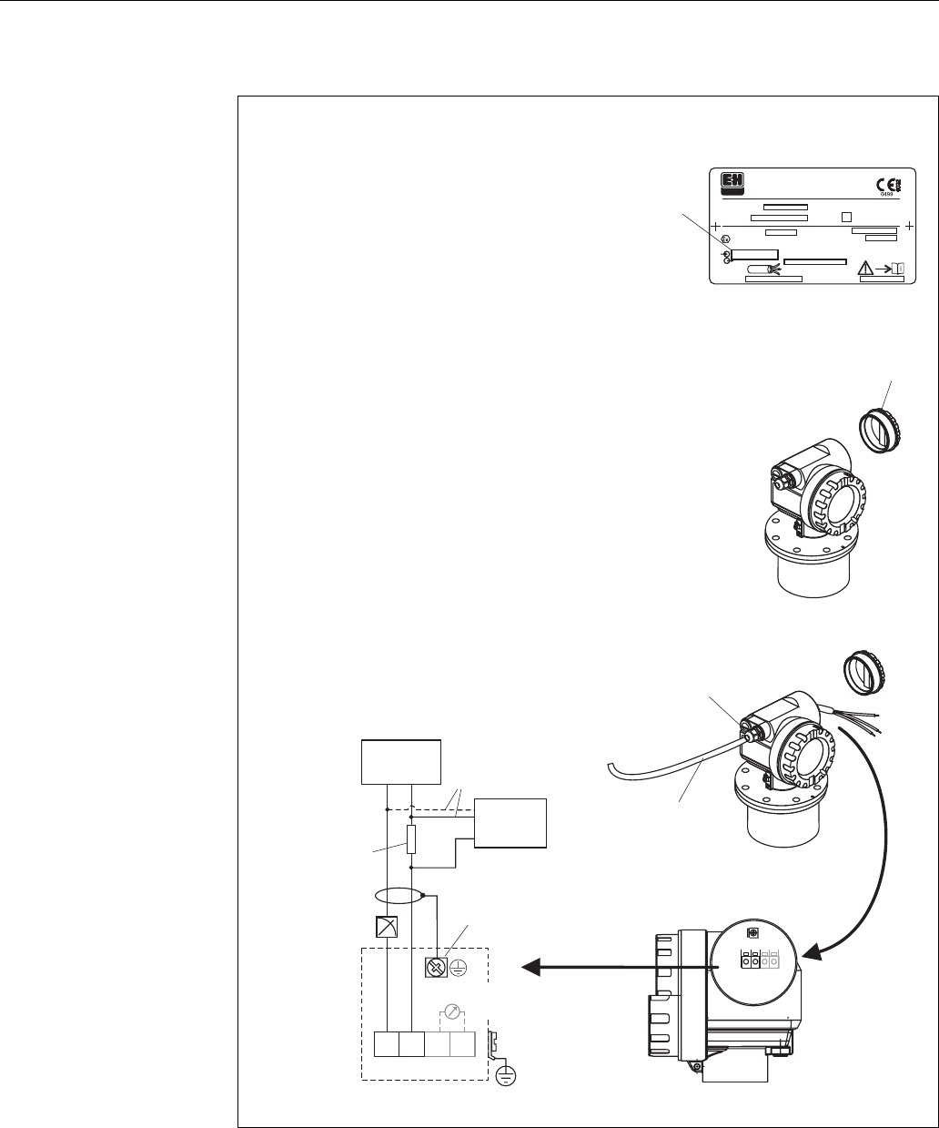
Wiring in T12 housing
L00-FMR2xxxx-04-00-00-en-014
2
-
-
4
3
5
1
Ser.-No.:
Order Code:
D00882-A
U 16 ... 30 V DC
4...20 mA
t >85°C
x=if modification
see sep. label
Dat./Insp.:
PN max.
T
Antenne max. °C
79689 Maulburg
Made in Germany
T >70°C:
A
MICROPILOT M
ENDRESS+HAUSER
PTB 00 ATEX
II 1/2 G EEx ia IIC T6
IP65
xxxxxxxx
xxxxxxxx
1
3
4
11
8
7
34
I+ I-
12
L- L+
4...20 mA
12 34
Caution!
"Before connection please note the following:
The power supply must be identical to the data on the
nameplate (1).
Switch off power supply before connecting up the device.
Connect Equipotential bonding to transmitter ground terminal
before connecting up the device.
Tighten the locking screw:
It forms the connection between the antenna and the housing
ground potential.
●
●
●
●
When you use the measuring system in hazardous areas, make sure you comply with
national standards and the specifications in the safety instructions (XA’s).
Make sure you use the specific cable gland.
Commubox
FXA 191
DXR 375
communication
resistor
(> 250 )Ω
alternatively
plant
ground
test sockets
(output current)
power
Connect up the Micropilot M as follows:
Before unscrew housing cover (2) at seperate connection room
turn off the power supply!
Insert cable (3) through gland (4).
A standard installation cable is sufficient if only the analogue signal is
used. Use a screened cable when working with a superimposed
communications signal (HART).
Only ground screening of the line (5) on sensor side.
Make connection (see pin assignment).
Tighten cable gland (4).
Screw on housing cover (2).
Switch on power supply.
●
●
●
●
●
Micropilot M FMR250 with HART/4...20 mA Wiring
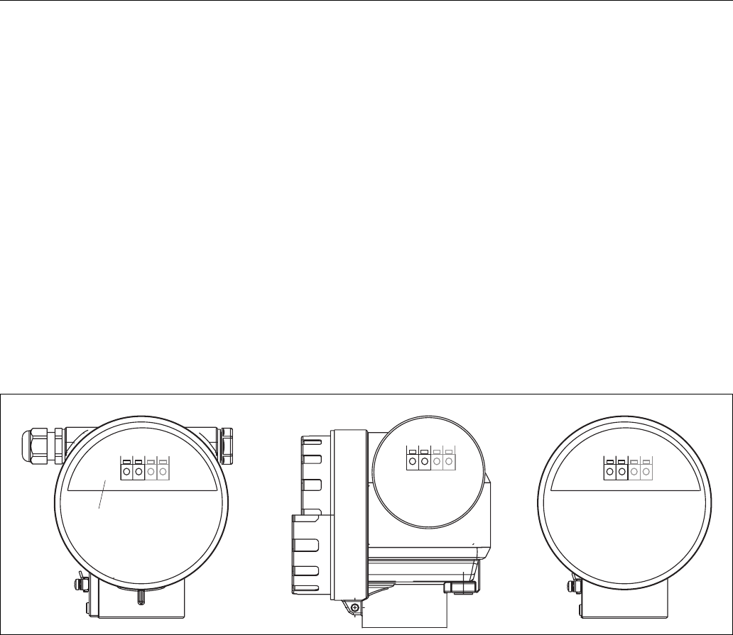
Endress + Hauser 27
4.2 Connecting the measuring unit
Terminal compartment
Three housings are available:
• Aluminium housing F12 with additionally sealed terminal compartment for:
–standard,
–EEx ia,
– EEx ia with dust Ex.
• Aluminium housing T12 with separate terminal compartment for:
–standard,
–EEx d,
– EEx ia (with overvoltage protection),
– dust Ex.
• 316L housing F23 for:
–standard,
–EEx ia,
– EEx ia with dust Ex.
The electronics and current output are galvanically isolated from the antenna circuit.
L00-FMR2xxxx-04-00-00-en-019
The instrument data are given on the nameplate together with important information regarding the
analog output and voltage supply. Housing orientation regarding the wiring, (→Page 24).
Load HART
Minimum load for Hart communication: 250 Ω
Cable entry
Cable gland: M20x1.5
Cable entry: G ½ or ½ NPT
1 1
2 2
3 3
4 4
1234
sealed terminal
compartment
F12 housing F23 housing
T12 housing
Wiring Micropilot M FMR250 with HART/4...20 mA
28 Endress + Hauser
Supply voltage
The following values are the voltages across the terminals directly at the instrument:
Power consumption
Normal operation: min. 60 mW, max. 900 mW
Current consumption
Communication Current
consumption
Terminal voltage
minimal maximal
HART
standard
4mA 16V 36V
20 mA 7.5 V 36 V
EEx ia
4mA 16V 30V
20 mA 7.5 V 30 V
EEx d
4mA 16V 30V
20 mA 11 V 30 V
dust Ex
4mA 16V 30V
20 mA 11 V 30 V
Fixed current, adjustable
e.g. for solar power
operation (measured
value transferred at
HART)
standard 11 mA 10 V 36 V
EExia 11mA 10V 30V
Fixed current for HART
Multidrop mode
standard 4 mA1)
1) Start up current 11 mA.
16 V 36 V
EEx ia 4 mA1) 16 V 30 V
Communication Current consumption
HART 3.6...22 mA
Micropilot M FMR250 with HART/4...20 mA Wiring
Endress + Hauser 29
4.2.1 HART connection with E+H RMA422 / RN221N
L00-FMR2xxxx-04-00-00-en-009
4.2.2 HART connection with other supplies
L00-FMR2xxxx-04-00-00-en-008
"Caution!
If the HART communication resistor is not built into the supply unit, it is necessary to insert a
communication resistor of 250 Ω into the 2-wire line.
4...20 mA
1234
ENDRESS + HAUSER
RMA 422
Commubox
FXA191
RMA422
RN221N
HART
DXR375
1
# % &
Copy
G H I
P Q R S
, ( )‘
A B C
Paste
Page
On
Page
Up
DeleteBksp
Insert
J K L
T UV
_ < >
D E F
Hot Key
+ Hot Key
M N O
W XY Z
+ * /
4
7
.
2
5
8
0
375
FIELD COMMUNICATOR
3
6
9
-
FMP40:LIC0001
ONLINE
1 GROUP SELECT
2 PV 8.7 m
HELP SAVE
dsdmdm
df das.
asdas fa
asas la.
FXA193
- ToF Tool -
FieldTool
Package
- ToF Tool -
FieldTool
Package
- FieldCare
1234
HART
DXR375
1
# % &
Copy
G H I
P Q R S
, ( )‘
A B C
Paste
Page
On
Page
Up
DeleteBksp
Insert
J K L
T UV
_ < >
D E F
Hot Key
+ Hot Key
M N O
W XY Z
+ * /
4
7
.
2
5
8
0
375
FIELD COMMUNICATOR
3
6
9
-
FMP40:LIC0001
ONLINE
1 GROUP SELECT
2 PV 8.7 m
HELP SAVE
dsdmdm
df das.
asdas fa
asas la.
- ToF Tool -
FieldTool
Package
- FieldCare
- ToF Tool -
FieldTool
Package
Commubox
FXA191
FXA193
≥Ω250
PLC
DC power supply
unit
or
4...20 mA

Wiring Micropilot M FMR250 with HART/4...20 mA
30 Endress + Hauser
4.3 Recommended connection
4.3.1 Equipotential bonding
Connect the equipotential bonding to the external ground terminal of the transmitter.
4.3.2 Wiring screened cable
"Caution!
In Ex applications, the screen must only be grounded on the sensor side. Further safety instructions
are given in the separate documentation for applications in explosion hazardous areas.
4.4 Degree of protection
• housing: IP 65, NEMA 4X (open housing and pulled out display: IP20, NEMA 1)
• antenna: IP 68 (NEMA 6P)
4.5 Post-connection check
After wiring the measuring instrument, perform the following checks:
• Is the terminal allocation correct (→Page 25 and Page 26)?
• Is the cable gland tight?
• Is the housing cover screwed tight?
• If auxiliary power is available:
Is the instrument ready for operation and does the liquid crystal display show any value?
Micropilot M FMR250 with HART/4...20 mA Operation
Endress + Hauser 31
5Operation
5.1 Quick operation guide
L00-FMR250xx-19-00-00-en-002
ENDRESS + HAUSER
E
+
–
XX
X
X
X
SS
S
S
S
S
O
O
O
O
O
O
F
F
F
F
F
>3 s
F
...
...
3x
...
...
unknown
DC: < 1.9
DC: 1.9 ... 4
DC: 4 ... 10
DC: > 10
unknown
DC: 1.6...1.9
DC: 1.9...2.5
DC: 2.5...4
DC: 4...7
DC: > 7
Example - Selection and configuration in Operation menu:
Group Selection
Function Group
unction
Note!
Selection menus:
function
Typing in numerals and text:
numeral / text
function
function
Group selection
Measured value display
1.) Change from Measured Value Display to by pressing
2.) Press or to select the required (e.g.. "basic setup (00)") and confirm by pressing
(e.g. "tank shape (002)") is selected.
The active selection is marked by a in front of the menu text.
3.) Activate Edit mode with or .
a) Select the required in selected (e.g. "tank shape (002)") with or .
b) confirms selection appears in front of the selected parameter
c) confirms the edited value system quits Edit mode
d) + (= ) interrupts selection system quits Edit mode
a) Press or to edit the first character of the (e.g. "empty calibr. (005)")
b) positions the cursor at the next character (a) until you have completed your input
c) if a symbol appears at the cursor, press to accept the value entered
system quits Edit mode
d) + (= ) interrupts the input,
4) Press to select the next (e.g. "medium property (003)")
5) Press + (= ) once return to previous (e.g. "tank shape (002)")
Press + (= ) twice return to
6) Press + (= ) to return to
F
SO
O
SO
F
S
X
S
F
S
F
F
OS X
OS
F
OX
F
OS X
OS
OX
➜
➜
➜
➜
➜
➜
➜
First f
continue with
system quits Edit mode
➜
Parameter
Return to
Group Selection
basic setup
safety settings
linearisation
extended
tank shape
vessel / silo
dome ceiling
horizontal cyl
bypass
stilling well
flat ceiling
sphere
medium property
medium property
media type
liquids
solids
unknown
metal silo
concrete silo
bin / bunker
dome
stockpile
conveyor belt
Operation Micropilot M FMR250 with HART/4...20 mA
32 Endress + Hauser
5.1.1 General structure of the operating menu
The operating menu is made up of two levels:
•Function groups (00, 01, 03, …, 0C, 0D): The individual operating options of the instrument
are split up roughly into different function groups. The function groups that are available include,
e.g.: "basic setup", "safety settings", "output", "display", etc.
•Functions (001, 002, 003, …, 0D8, 0D9): Each function group consists of one or more
functions. The functions perform the actual operation or parameterisation of the instrument.
Numerical values can be entered here and parameters can be selected and saved. The available
functions of the “basic setup” (00) function group include, e.g.: "tank shape" (002),
"medium property" (003), "process cond." (004), "empty calibr." (005), etc.
If, for example, the application of the instrument is to be changed, carry out the following
procedure:
1. Select the “basic setup” (00) function group.
2. Select the "tank shape" (002) function (where the existing tank shape is selected).
5.1.2 Identifying the functions
For simple orientation within the function menus (QUERVERWEIS), for each function a position is
shown on the display.
L00-FMRxxxxx-07-00-00-en-005
The first two digits identify the function group:
The third digit numbers the individual functions within the function group:
Hereafter the position is always given in brackets (e.g. "tank shape" (002)) after the described
function.
•basic setup 00
•safety settings 01
•linearisation 04
. . .
•basic setup 00 →•tank shape 002
•medium property 003
•process cond. 004
. . .
Micropilot M FMR250 with HART/4...20 mA Operation
Endress + Hauser 33
5.2 Display and operating elements
L00-FMxxxxxx-07-00-00-en-001
Fig. 2: Layout of the display and operating elements
!Note!
To access the display the cover of the electronic compartment may be removed even in hazardous
area (IS and XP).
5.2.1 Display
Liquid crystal display (LCD):
Four lines with 20 characters each. Display contrast adjustable through key combination.
L00-FMRxxxxx-07-00-00-en-002
Fig. 3: Display
ENDRESS + HAUSER
E
+
–
ENDRESS+HAUSER
MICROPILOT II
ENDRESS+HAUSER
MICROPILOT II
IP 65
IP 65
Order Code:
Ser.-No.:
Order Code:
Ser.-No.:
Messbereich
Measuring range
Messbereich
Measuring range
U 16...36V DC
4...20 mA
U 16...36V DC
4...20 mA
max.20 m
max.20 m
Made in Germany Maulburg
Made in Germany Maulburg
T>
70°C :
At >85°C
T>
70°C :
At >85°C
LCD
(liquid crystal display)
Symbols 3 keys
XX
X
X
S
S
O
OFF
F
F
HOME
FG00 F000 F001 F002 F003 F004 ...
FG01
FG02
FG03
FG04
FG05
FG06
FG07
...
+21dB 09C
10.002.305m
0.00
ENDRESS + HAUSER
E
+
–
Headline Position indicator
Main value
Unit
Symbol
Selection list
Function groups -> Functions
Help text
Envelope
curve
Bargraph
Operation Micropilot M FMR250 with HART/4...20 mA
34 Endress + Hauser
5.2.2 Display symbols
The following table describes the symbols that appear on the liquid crystal display:
5.2.3 Key assignment
The operating elements are located inside the housing and are accessible for operation by opening
the lid of the housing.
Function of the keys
Sybmol Meaning
ALARM_SYMBOL
This alarm symbol appears when the instrument is in an alarm state. If the symbol flashes, this indicates a
warning.
LOCK_SYMBOL
This lock symbol appears when the instrument is locked,i.e. if no input is possible.
COM_SYMBOL
This communication symbol appears when a data transmission via e.g. HART, PFOFIBUS-PA or
Foundation Fieldbus is in progress.
Key(s) Meaning
O or VNavigate upwards in the selection list
Edit numeric value within a function
S or VNavigate downwards in the selection list
Edit numeric value within a function
X or ZNavigate to the left within a function group
FNavigate to the right within a function group, confirmation.
O and F
or
S and FContrast settings of the LCD
O and S and F
Hardware lock / unlock
After a hardware lock, an operation of the instrument via display or
communication is not possible!
The hardware can only be unlocked via the display. An unlock parameter must
be entered to do so.
Micropilot M FMR250 with HART/4...20 mA Operation
Endress + Hauser 35
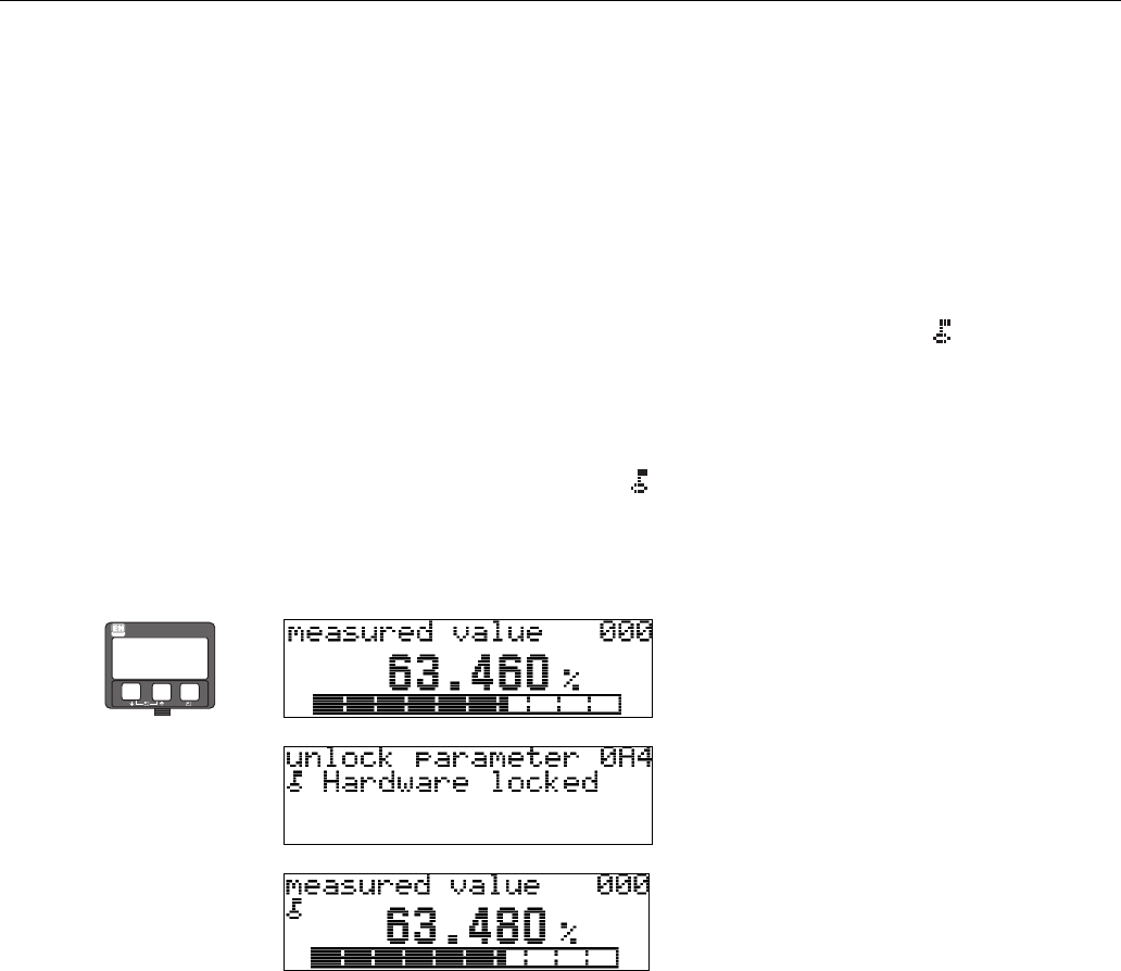
5.3 Local operation
5.3.1 Locking of the configuration mode
The Micropilot can be protected in two ways against unauthorised changing of instrument data,
numerical values or factory settings:
"unlock parameter" (0A4):
A value <> 100 (e.g. 99) must be entered in "unlock parameter"(0A4) in the
"diagnostics"(0A) function group. The lock is shown on the display by the symbol and can be
released again either via the display or by communication.
Hardware lock:
The instrument is locked by pressing the O and S and F keys at the same time.
The lock is shown on the display by the symbol and can only be unlocked again
via the display by pressing the O and S and F keys at the same time again. It is not possible to
unlock the hardware by communication. All parameters can de displayed even if the instrument is
locked.
⇒O and S and F press simultaneous
⇓
⇓
The LOCK_SYMBOL appears on the LCD.
ENDRESS + HAUSER
E
+
–
Operation Micropilot M FMR250 with HART/4...20 mA
36 Endress + Hauser
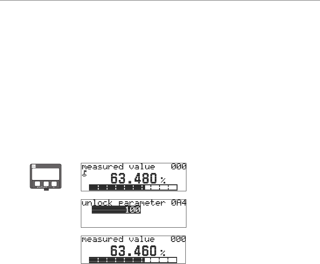
5.3.2 Unlocking of configuration mode
If an attempt is made to change parameters on display when the instrument is locked, the user is
automatically requested to unlock the instrument:
unlock parameter" (0A4):
By entering the unlock parameter (on the display or via communication)
100 = for HART devices
the Micropilot is released for operation.
Hardware unlock:
After pressing the O and S and F keys at the same time, the user is asked to enter the unlock
parameter
100 = for HART devices.
"Caution!
Changing certain parameters such as all sensor characteristics, for example, influences numerous
functions of the entire measuring system, particularly measuring accuracy. There is no need to
change these parameters under normal circumstances and consequently, they are protected by a
special code known only to the E+H service organization. Please contact Endress+Hauser if you
have any questions.
⇒O and S and F press simultaneous
⇓
Please enter unlock code and confirm with F.
⇓
ENDRESS + HAUSER
E
+
–
Micropilot M FMR250 with HART/4...20 mA Operation
Endress + Hauser 37
5.3.3 Factory settings (Reset)
"Caution!
A reset sets the instrument back to the factory settings. This can lead to an impairment of the
measurement. Generally, you should perform a basic setup again following a reset.
A reset is only necessary:
• if the instrument no longer functions
• if the instrument must be moved from one measuring point to another
• if the instrument is being de-installed /put into storage/installed
User input ("reset" (0A3)):
• 333 = customer parameters
333 = reset customer parameters
This reset is recommended whenever an instrument with an unknown 'history' is to be used in an
application:
• The Micropilot is reset to the default values.
• The customer specific tank map is not deleted.
• A linearisation is switched to "linear" although the table values are retained. The table can be
reactivated in the "linearisation"(04) function group.
List of functions that are affected by a reset:
The tank map can also be reset in the "mapping"(055) function of the "extended calibr."(05)
function group.
This reset is recommended whenever an instrument with an unknown 'history' is to be used in an
application or if a faulty mapping was started:
• The tank map is deleted. The mapping must be recommenced.
⇒
ENDRESS + HAUSER
E
+
–
⇒
ENDRESS + HAUSER
E
+
–
• tank shape (002) - liquids only
• vessel / silo (00A) - solids only
• empty calibr. (005)
• full calibr. (006)
• pipe diameter (007) - liquids only
• output on alarm (010)
• output on alarm (011)
• outp. echo loss (012)
• ramp %span/min (013)
• delay time (014)
• safety distance (015)
• in safety dist. (016)
• level/ullage (040)
• linearisation (041)
• customer unit (042)
• diameter vessel (047)
• range of mapping (052)
• pres. Map dist (054)
• offset (057)
• low output limit (062)
• fixed current (063)
• fixed cur. value (064)
• simulation (065)
• simulation value (066)
• 4mA value (068)
•20mA value (069)
• format display (094)
• distance unit (0C5)
• download mode (0C8)
Operation Micropilot M FMR250 with HART/4...20 mA
38 Endress + Hauser
5.4 Display and acknowledging error messages
Type of error
Errors that occur during commissioning or measuring are displayed immediately on the local
display. If two or more system or process errors occur, the error with the highest priority is the one
shown on the display.
The measuring system distinguishes between two types of error:
•A (Alarm):
Instrument goes into a defined state (e.g. MAX 22 mA)
Indicated by a constant symbol.
(For a description of the codes, see Page 67)
•W (Warning):
Instrument continue measuring, error message is displayed.
Indicated by a flashing symbol.
(For a description of the codes, see Page 67)
•E (Alarm / Warning):
Configurable (e.g. loss of echo, level within the safety distance)
Indicated by a constant/flashing symbol.
(For a description of the codes, see Page 67)
5.4.1 Error messages
Error messages appear as four lines of plain text on the display. In addition, a unique error code is
also output. A description of the error codes is given on Page 67.
•The "diagnostics" (0A) function group can display current errors as well as the last errors that
occurred.
• If several current errors occur, use O or S to page through the error messages.
• The last occurring error can be deleted in the "diagnostics" (0A) function group
with the funktion"clear last error" (0A2).
⇒
ENDRESS + HAUSER
E
+
–
Micropilot M FMR250 with HART/4...20 mA Operation
Endress + Hauser 39
5.5 HART communication
Apart from local operation, you can also parameterise the measuring instrument and view measured
values by means of a HART protocol. There are two options available for operation:
• Operation via the universal handheld operating unit, the HART Communicator DXR375.
• Operation via the Personal Computer (PC) using the operating program (e.g. ToF Tool or
Commuwin II) (For connections, see Page 29).
!Note!
The Micropilot M can also be operated locally using the keys. If operation is prevented by the keys
being locked locally, parameter entry via communication is not possible either.
5.5.1 Handheld unit Field Communicator DXR375
All device functions can be adjusted via menu operation with the handheld unit DXR375.
L00-FMR2xxxx-07-00-00-yy-007
Abb. 4: Menu operation with the DXR375 handheld instrument
!Note!
• Further information on the HART handheld unit is given in the respective operating manual
included in the transport bag of the instrument.
5.5.2 ToF Tool operating program
The ToF Tool is a graphical operating software for instruments from Endress+Hauser that operate
based on the time-of-flight principle. It is used to support commissioning, securing of data, signal
analysis and documentation of the instruments. It is compatible with the following operating
systems: WinNT4.0, Win2000 and WinXP.
The ToF Tool supports the following functions:
• Online configuration of transmitters
• Signal analysis via envelope curve
• Tank linearisation
• Loading and saving of instrument data (Upload/Download)
• Documentation of measuring point
!Note!
Further information you may find on the CD-ROM, which is enclosed to the instrument.
1
# % &
Copy
G H I
P Q R S
, ( ) ‘
A B C
Paste
Page
On
Page
Up
DeleteBksp
Insert
J K L
T U V
_ < >
D E F
Hot Key
+ Hot Key
M N O
W X Y Z
+ * /
4
7
.
2
5
8
0
375
FIELD COMMUNICATOR
3
6
9
-
96
FMR231: LIC0001
ONLINE
1 GROUP SELECT
2 PV 8.7 m
HELP SAVE
dsdmdm
df das.
asdas fa
asas la.
Page
On
Page
Up
Bksp
Delete
Delete
FMR231: LIC0001
ONLINE
1 GROUP SELECTION
2 PV 8.7 m
HELP SAVE
dsdmdm
df das.
asdas fa
asas la.
FMR231: LIC0001
GROUP SELECTION
HOMESAVE
dsdmdm
df das.
asdas fa
asas la.
H
FMR231: LIC0001
HOMESAVE
dsdmdm
df das.
asdas fa
asas la.
H
Bksp
1 BASIC SETUP
2 SAFETY SETTINGS
BASIC SETUP
1 MEASURED VALUE
4 PROCESS COND.
5 EMPTY CALIBR.
3 MEDIUM PROPERTY
4 EXTENDED CALIB.
5 OUTPUT
3 LINEARISATION
2 TANK SHAPE
Operation Micropilot M FMR250 with HART/4...20 mA
40 Endress + Hauser
Menu-guided commissioning
L00-FMR250xx-20-00-00-en-011
Signal analysis via envelope curve:
L00-FMR250xx-20-00-00-en-008
Connection options
• Service-interface with adapter FXA193 (see Page 29)
• HART with Commubox FXA191 (see Page 29)
Micropilot M FMR250 with HART/4...20 mA Commissioning
Endress + Hauser 41
6 Commissioning
6.1 Function check
Make sure that all final checks have been completed before you start up your measuring point:
• Checklist “Post installation check” (see Page 24).
• Checklist “Post connection check” (see Page 30).
6.2 Switching on the measuring device
When the instrument is switched on for the first time, the following messages appear on the display:
⇒
⇓After 5 s, the following message appears
⇓After 5 s, the following message appears(e.g. for HART
devices)
⇓After 5 s or after you have pressed F the following
message appears
Select the language (this message appears the first time
the instrument is switched on)
⇓
Select the basic unit (this message appears the first time
the instrument is switched on)
⇓
The current measured value is displayed
⇓After F is pressed, you reach the group selection.
This selection enables you to perform the basic setup
ENDRESS + HAUSER
E
+
–
Commissioning Micropilot M FMR250 with HART/4...20 mA
42 Endress + Hauser
6.3 Basic Setup
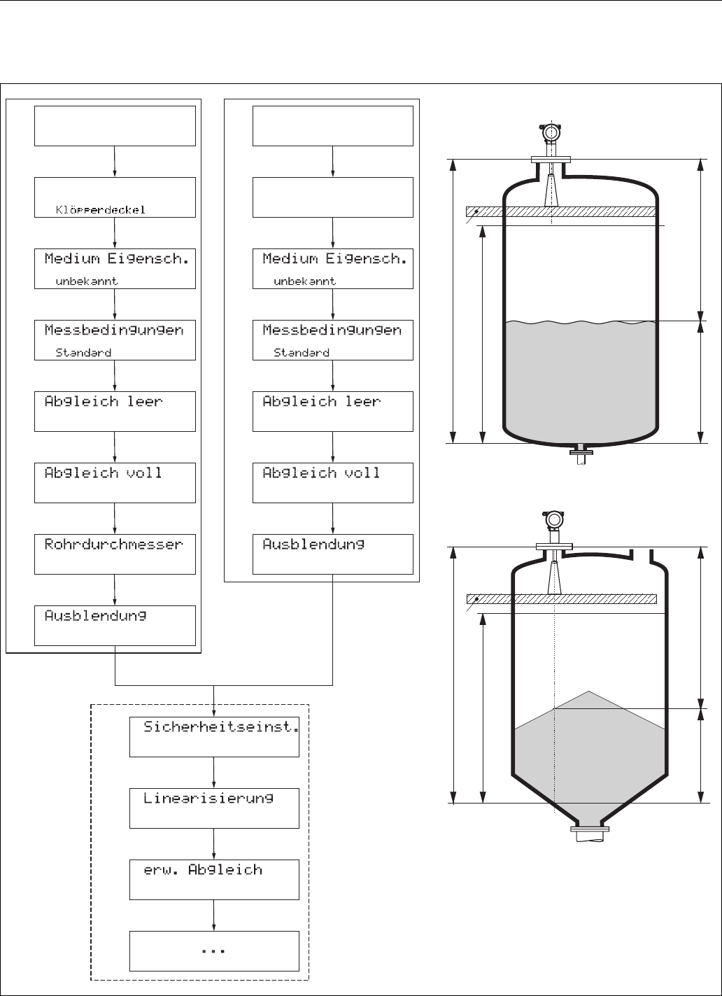
L00-FMR250xx-19-00-00-de-001
SD
SD
F
F
L
L
D
D
E
E
Flansch:
Referenzpunkt
der Messung
Flansch:
Referenzpunkt
der Messung
Tankgeometrie Behälter / Silo
Mediumtyp Mediumtyp
(für Bypass/Schwallrohr)
(Beschreibung siehe BA 291F)
E = Abgleich Leer (= Nullpunkt), Einstellung in 005
F = Abgleich Voll (= Spanne), Einstellung in 006
D = Distanz (Abstand Flansch / Füllgut), Anzeige in 0A5
L=Füllstand, Anzeige in 0A6
SD = Sicherheitsabstand, Einstellung in 015
Grundabgleich (Standard - Flüssigkeiten)
Grundabgleich (Standard - Schüttgüter)
Optional
Flüssigkeit Schüttgut
Metallsilo
Füllstandmessung in Flüssigkeiten
Füllstandmessung in Schüttgütern

Micropilot M FMR250 with HART/4...20 mA Commissioning
Endress + Hauser 43
The basic setup is sufficient for successful commissioning in most applications. Complex measuring
operations necessitate additional functions that the user can use to customise the Micropilot as
necessary to suit his specific requirements. The functions available to do this are described in detail
in the BA291F.
Comply with the following instructions when configuring the functions in the "basic setup" (00):
• Select the functions as described on Page 31.
• Some functions can only be used depending on the parameterisation of the instrument. For
example, the pipe diameter of a stilling well can only be entered if "stilling well" was selected
beforehand in the "tank shape" (002) function.
• Certain functions (e.g. starting an interference echo mapping (053)) prompt you to confirm your
data entries. Press O or S to select "YES" and press F to confirm. The function is now started.
• If you do not press a key during a configurable time period (→ function group "display"(09)),
an automatic return is made to the home position (measured value display).
!Note!
• The instrument continues to measure while data entry is in progress, i.e. the current measured
values are output via the signal outputs in the normal way.
• If the envelope curve mode is active on the display, the measured values are updated in a slower
cycle time. Thus, it is advisable to leave the envelope curve mode after the measuring point has
been optimised.
• If the power supply fails, all preset and parameterised values remain safely stored in the EEPROM.
"Caution!
All functions are described in detail, as is the overview of the operating menu itself, in the manual
“Description of the instrument functions − BA291F”, which is found on the enclosed CD-
ROM.
!Note!
The default values of the parameters are typed in boldface.
Commissioning Micropilot M FMR250 with HART/4...20 mA
44 Endress + Hauser
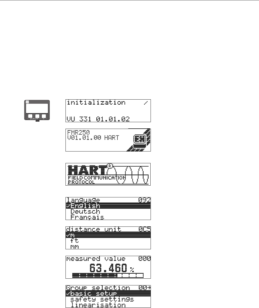
6.4 Basic Setup with the VU331
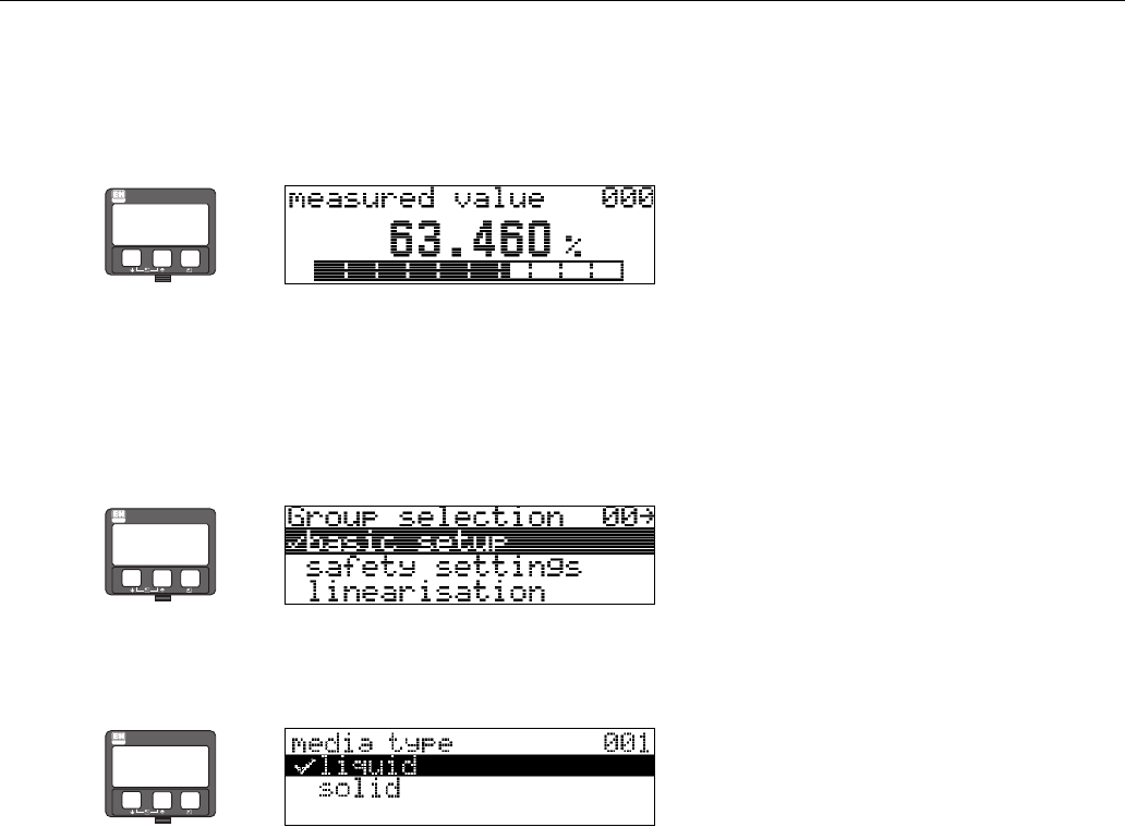
Function "measured value" (000)
This function displays the current measured value in the selected unit
(see "customer unit"(042) function). The number of digits after decimal point can be selected in
the "no.of decimals"(095) function.
6.4.1 Function group "basic setup" (00)
Function "media type" (001)
This function is used to select the media type.
Selection:
• liquid
•solid
⇒
ENDRESS + HAUSER
E
+
–
⇒
ENDRESS + HAUSER
E
+
–
⇒
ENDRESS + HAUSER
E
+
–
With the selection "liquid" only the
following functions can be adjusted:
With the selection "solids" only the
following functions can be adjusted:
• tank shape 002 • vessel / silo 00A
• medium property 003 • medium property 00B
• process cond. 004 • process cond. 00C
• empty calibr. 005 • empty calibr. 005
• full calibr. 006 • full calibr. 006
• pipe diameter 007 • check distance 051
• check distance 051 • range of mapping 052
• range of mapping 052 • start mapping 053
• start mapping 053 • . . .
•. . .
Micropilot M FMR250 with HART/4...20 mA Commissioning
Endress + Hauser 45
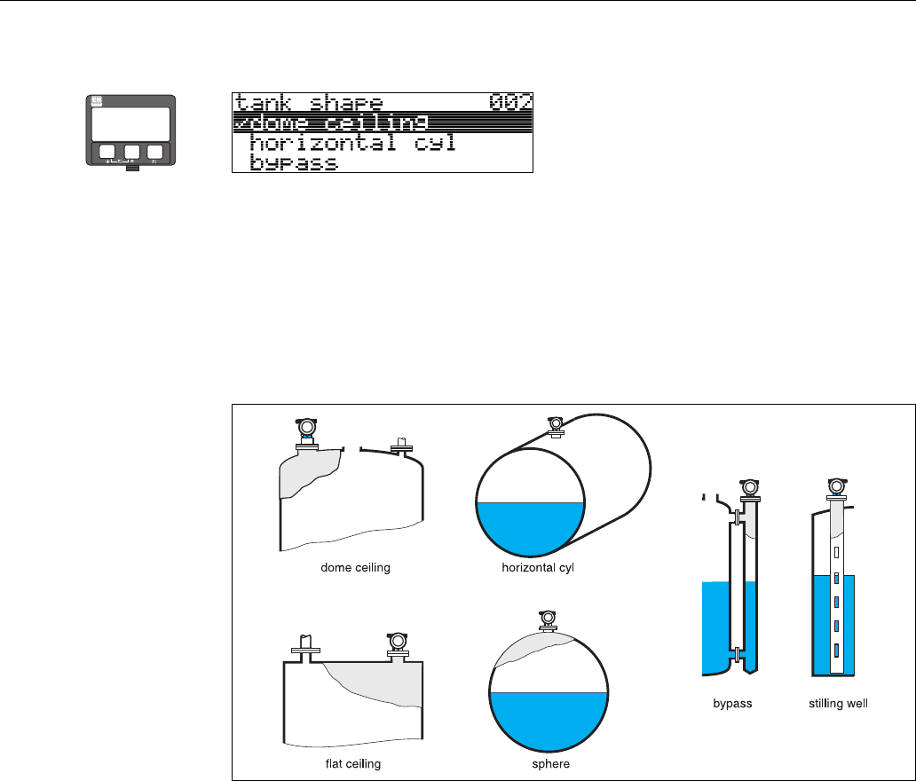
Function "tank shape" (002), liquids only
This function is used to select the tank shape.
Selection:
•dome ceiling
• horizontal cyl
•bypass
• stilling well
• flat ceiling
•sphere
L00-FMR2xxxx-14-00-06-en-007
⇒
ENDRESS + HAUSER
E
+
–
Commissioning Micropilot M FMR250 with HART/4...20 mA
46 Endress + Hauser
Function "medium property" (003), liquids only
This function is used to select the dielectric constant.
Selection:
•unknown
•DC: < 1.9
• DC: 1.9 ... 4
• DC: 4 ... 10
•DC: > 10
⇒
ENDRESS + HAUSER
E
+
–
Product class DC (εr) Examples
A1,4...1,9 non-conducting liquids, e.g. liquefied gas 1
1) Treat Ammonia NH3 as a medium of group A, i.e. use FMR 230 in a stilling well.
B1,9...4 non-conducting liquids, e.g. benzene, oil, toluene, …
C4...10 e.g. concentrated acids, organic solvents, esters, aniline, alcohol, acetone, …
D>10 conducting liquids, e.g. aqueous solutions, dilute acids and alkalis
Micropilot M FMR250 with HART/4...20 mA Commissioning
Endress + Hauser 47
Function "process cond." (004) , liquids only
This function is used to select the process conditions.
Selection:
•standard
• calm surface
•turb. surface
• agitator
• fast change
• test:no filter
⇒
ENDRESS + HAUSER
E
+
–
standard calm surface turb. surface
For all applications that do not fit into
any of the following groups.
Storage tanks with immersion tube or
bottom filling
Storage / buffer tanks with rough
surface due to free filling or mixer
nozzles
The filter and output damping are set
to average values.
The averaging filters and output
damping are set to high values.
→ steady meas. value
→ precise measurement
→ slower reaction time
Special filters to smooth the input
signals are emphasised.
→ smoothed meas. value
→ medium fast reaction time
agitator fast change test:no filter
Agitated surfaces (with possible
vortex) due to agitators
Rapid change of level, particularly in
small tanks
All filters can be switched off for service
/ diagnostic purposes.
Special filters to smooth the input
signals are set to high values.
→ smoothed meas. value
→ medium fast reaction time
→ minimization of effects by agitator
blades
The averaging filters are set to low
values. The output damping is set to 0.
→ rapid reaction time
→ possibly unsteady meas. value
All filters off.
Commissioning Micropilot M FMR250 with HART/4...20 mA
48 Endress + Hauser
Function "vessel / silo" (00A), solids only
This function is used to select the vessel / silo.
Selection:
•unknown
• metal silo
• concrete silo
•bin / bunker
•dome
• stockpile
• conveyor belt
Function "medium property" (00B), solids only
This function is used to select the dielectric constant.
Selection:
•unknown
• DC: 1.6 ... 1.9
• DC: 1.9 ... 2.5
• DC: 2.5 ... 4
• DC: 4 ... 7
•DC: > 7
The respective lower group applies for very loose or loosened bulk solids.
⇒
ENDRESS + HAUSER
E
+
–
⇒
ENDRESS + HAUSER
E
+
–
Media group DK (εr) Examples
A1.6...1.9
– Plastic granulate
– White lime, special cement
–Sugar
B1.9...2.5 – Portland cement, plaster
C2.5...4
–Grain, seeds
–Ground stones
–Sand
D4...7 – Naturally moist (ground) stones, ores
–Salt
E>7
– Metallic powder
– Carbon black
–Coal

Micropilot M FMR250 with HART/4...20 mA Commissioning
Endress + Hauser 49
Function "process cond." (00C), solids only
This function is used to select the process conditions.
Selection:
•standard
• fast change
• slow change
• test:no filter
⇒
ENDRESS + HAUSER
E
+
–
Commissioning Micropilot M FMR250 with HART/4...20 mA
50 Endress + Hauser
Function "empty calibr." (005)
This function is used to enter the distance from the flange (reference point of the measurement) to
the minimum level (=zero).
L00-FMR2xxxx-14-00-06-en-008
"Caution!
For dish bottoms or conical outlets, the zero point should be no lower than the point at which the
radar beam hits the bottom of the vessel.
⇒
ENDRESS + HAUSER
E
+
–
Micropilot M FMR250 with HART/4...20 mA Commissioning
Endress + Hauser 51
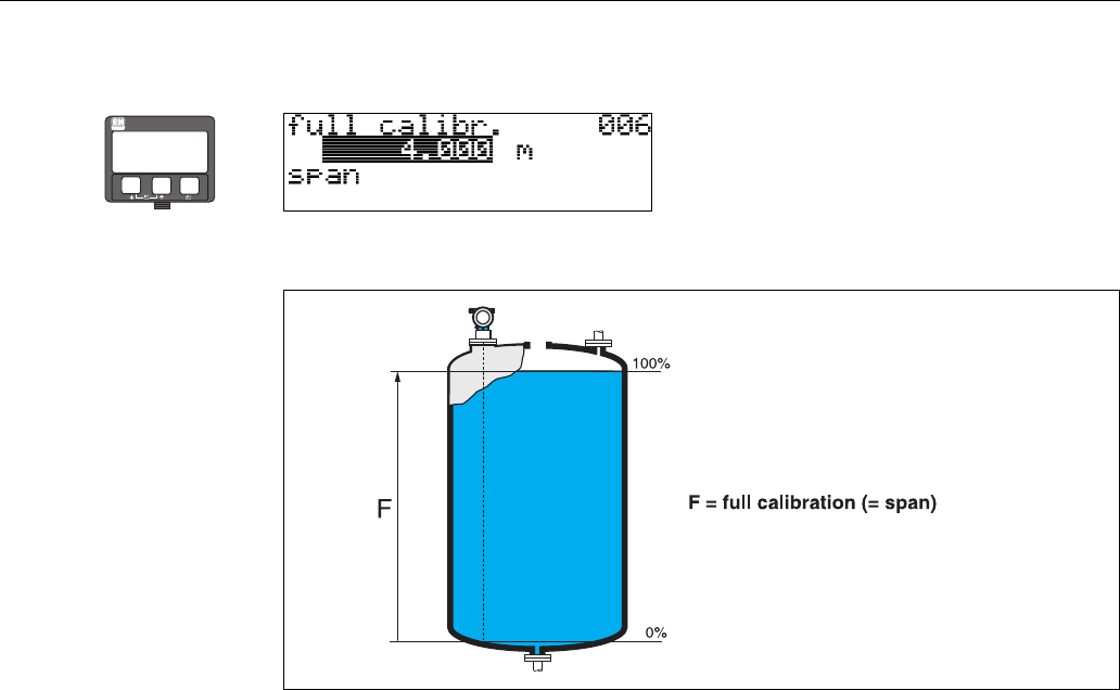
Function "full calibr." (006)
This function is used to enter the distance from the minimum level to the maximum level (=span).
L00-FMR2xxxx-14-00-06-en-009
In principle, it is possible to measure up to the tip of the antenna. However, due to considerations
regarding corrosion and build-up, the end of the measuring range should not be chosen any closer
than 50 mm (2") to the tip of the antenna.
!Note!
If bypass or stilling well was selected in the "tank shape" (002) function, the pipe diameter is
requested in the following step.
⇒
ENDRESS + HAUSER
E
+
–
Commissioning Micropilot M FMR250 with HART/4...20 mA
52 Endress + Hauser
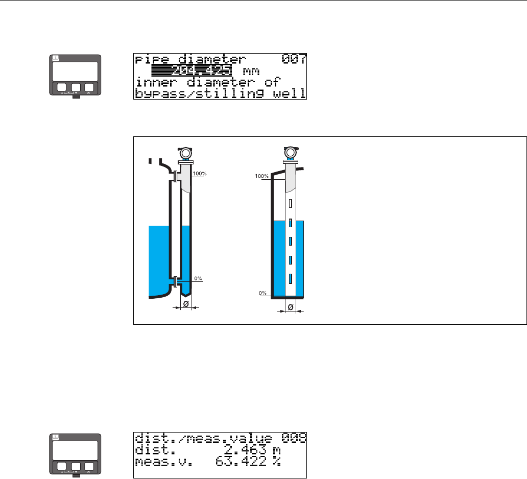
Function "pipe diameter" (007)
This function is used to enter the pipe diameter of the stilling well or bypass pipe.
L00-FMR2xxxx-14-00-00-en-011
Microwaves propagate more slowly in pipes than in free space. This effect depends on the inside
diameter of the pipe and is automatically taken into account by the Micropilot. It is only necessary
to enter the pipe diameter for applications in a bypass or stilling well.
display (008)
The distance measured from the reference point to the product surface and the level calculated
with the aid of the empty adjustment are displayed. Check whether the values correspond to the
actual level or the actual distance. The following cases can occur:
• Distance correct − level correct → continue with the next function, "check distance"(051)
• Distance correct − level incorrect → Check "empty calibr." (005)
• Distance incorrect − level incorrect → continue with the next function, "check distance"(051)
⇒
ENDRESS + HAUSER
E
+
–
⇒
ENDRESS + HAUSER
E
+
–
Micropilot M FMR250 with HART/4...20 mA Commissioning
Endress + Hauser 53
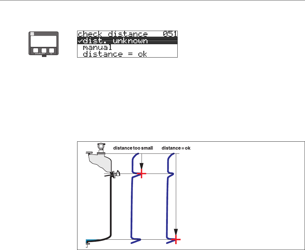
Function "check distance" (051)
This function triggers the mapping of interference echoes. To do so, the measured distance must be
compared with the actual distance to the product surface. The following options are available for
selection:
Selection:
•distance = ok
• dist. too small
• dist. too big
•dist. unknown
•manual
L00_FMR2xxxxx-14-00-06-en-010
distance = ok
• mapping is carried out up to the currently measured echo
• The range to be suppressed is suggested in the "range of mapping" (052) function
Anyway, it is wise to carry out a mapping even in this case.
dist. too small
• At the moment, an interference is being evaluated
• Therefore, a mapping is carried out including the presently measured echoes
• The range to be suppressed is suggested in the "range of mapping" (052) function
dist. too big
• This error cannot be remedied by interference echo mapping
• Check the application parameters (002), (003), (004) and "empty calibr."(005)
dist. unknown
If the actual distance is not known, no mapping can be carried out.
manual
A mapping is also possible by manual entry of the range to be suppressed. This entry is made in the
"range of mapping" (052) function.
"Caution!
The range of mapping must end 0.5 m (20") before the echo of the actual level. For an empty vessel,
do not enter E, but E – 0.5 m (20").
If a mapping already exists, it is overwriten up to the distance specified in
"range of mapping"(052). Beyond this value the existing mapping remains unchanged.
⇒
ENDRESS + HAUSER
E
+
–
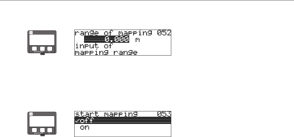
Commissioning Micropilot M FMR250 with HART/4...20 mA
54 Endress + Hauser
Function "range of mapping" (052)
This function displays the suggested range of mapping. The reference point is always the reference
point of the measurement (see Page 42 ff.). This value can be edited by the operator.
For manual mapping, the default value is 0 m.
Function "start mapping" (053)
This function is used to start the interference echo mapping up to the distance given in "range of
mapping"(052).
Selection:
•off → no mapping is carried out
•on → mapping is started
During the mapping process the message "record mapping" is displayed.
"Caution!
A mapping will be recorded only, if the device is not in alarm-state.
⇒
ENDRESS + HAUSER
E
+
–
⇒
ENDRESS + HAUSER
E
+
–
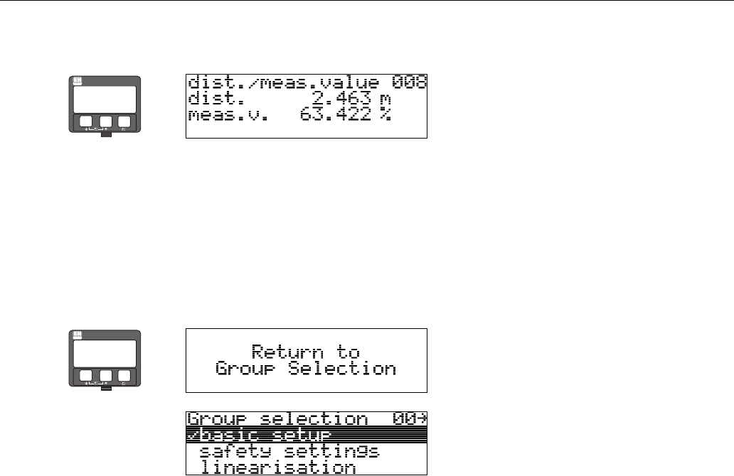
Micropilot M FMR250 with HART/4...20 mA Commissioning
Endress + Hauser 55
display (008)
The distance measured from the reference point to the product surface and the level calculated
with the aid of the empty adjustment are displayed. Check whether the values correspond to the
actual level or the actual distance. The following cases can occur:
• Distance correct − level correct → continue with the next function, "check distance"(051)
• Distance correct − level incorrect → Check "empty calibr." (005)
• Distance incorrect − level incorrect → continue with the next function, "check distance"(051)
⇒
ENDRESS + HAUSER
E
+
–
⇒
⇓After 3 s, the following message appears
ENDRESS + HAUSER
E
+
–
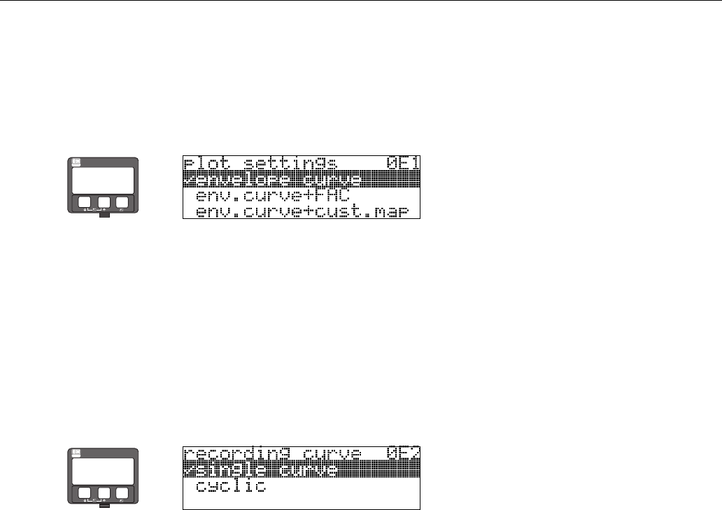
Commissioning Micropilot M FMR250 with HART/4...20 mA
56 Endress + Hauser
6.4.2 Envelope curve with VU331
After the basic setup, an evaluation of the measurement with the aid of the envelope curve
("envelope curve"(0E) function group) is recommended.
Function "plot settings" (0E1)
Select which information will be displayed in the LCD:
•envelope curve
• env.curve+FAC (on FAC see BA291F)
• env.curve+cust.map (i.e. customer tank map is also displayed)
Function "recording curve" (0E2)
This function defines whether the envelope curve is read as a
•single curve
or
• cyclic.
!Note!
If the cyclical envelope curve is active in the display, the measured value is refreshed in a slower
cycle time. It is therefore recommended to exit the envelope curve display after optimising the
measuring point.
!Note!
An orientation of the Micropilot can help to optimise measurement in applications with very weak
level echos or strong interference echos by increasing the useful echo/reducing the interference
echo (see "Orientation of the Micropilot" on Page 73).
When using the Wave Guide antenna: No orientation is required!
⇒
ENDRESS + HAUSER
E
+
–
⇒
ENDRESS + HAUSER
E
+
–
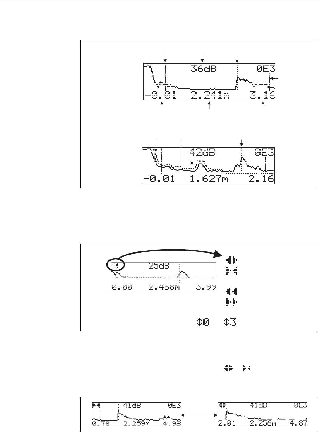
Micropilot M FMR250 with HART/4...20 mA Commissioning
Endress + Hauser 57
Function "envelope curve display" (0E3)
The envelope curve is displayed in this function. You can use it to obtain the following information:
L00-FMU4xxxx-07-00-00-en-003
Navigating in the envelope curve display
Using navigation, the envelope curve can be scaled horizontally and vertically and shifted to the left
or the right. The active navigation mode is indicated by a symbol in the top left hand corner of the
display.
L00-FMxxxxxx-07-00-00-en-004
Horizontal Zoom mode
Firstly, go into the envelope curve display. Then press O or S to switch to the envelope curve
navigation. You are then in Horizontal Zoom mode. Either or is displayed.
•O increases the horizontal scale.
•S reduces the horizontal scale.
L00-FMxxxxxx-07-00-00-yy-007
minimum distance
of the plot
maximum distance
of the plot
distance of
evaluated echo
interference echo
evaluated echo
is marked
quality of
evaluated echo
empty calibr.
envelope curve
only
envelope curve and
interference echo
suppression (map)
level echo
map
full calibr.
…
OE3
Move mode:
- m
-
oved to the left
moved to the right
Horizontal Zoom mode:
- h
-
orizontal zoom in
horizontal zoom out
Vertical Zoom mode:
- vertical zoom (4 steps)
O
S
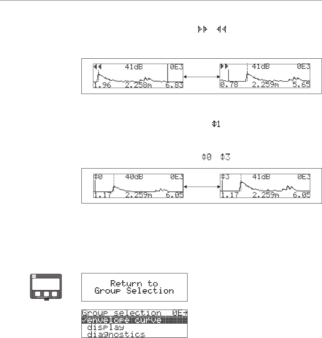
Commissioning Micropilot M FMR250 with HART/4...20 mA
58 Endress + Hauser
Move mode
Then press F to switch to Move mode. Either or is displayed.
•O shifts the curve to the right.
•S shifts the curve to the left.
L00-FMxxxxxx-07-00-00-yy-008
Vertical Zoom mode
Press F once more to switch to Vertical Zoom mode. is displayed. You now have the following
options.
•O increases the vertical scale.
•S reduces the vertical scale.
The display icon shows the current zoom factor ( to ).
L00-FMxxxxxx-07-00-00-yy-009
Exiting the navigation
•Press
F again to run through the different modes of the envelope curve navigation.
•Press
O and S to exit the navigation. The set increases and shifts are retained. Only when you
reactivate the "recording curve" (0E2) function does the Micropilot use the standard display
again.
O
S
O
S
⇒
⇓After 3 s, the following message appears
ENDRESS + HAUSER
E
+
–
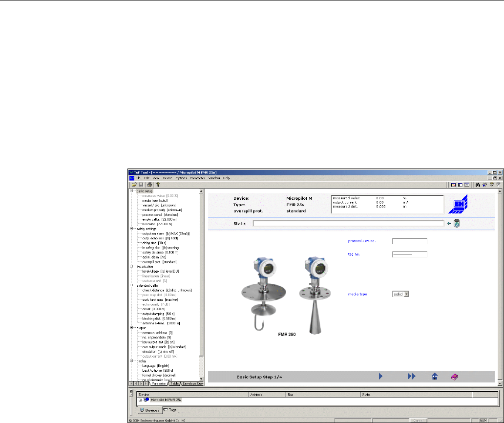
Micropilot M FMR250 with HART/4...20 mA Commissioning
Endress + Hauser 59
6.5 Basic Setup with the ToF Tool
To carry out the basic setup with the ToF Tool operating program, proceed as follows:
• Start the ToF Tool operating program and establish a connection
• Select the "basic setup" function group in the navigation window
The following display appears on the screen:
Basic Setup step 1/4:
•Status image
• Enter the measuring point description (TAG number).
L00-FMR250xx-20-00-00-en-010
!Note!
Each parameter that is changed must be confirmed with the RETURN key!
•If "solid" is selected in the "media type" function for level measurement in solids (for a
description, see Page 44).
•The "Next" button moves you to the next screen display:
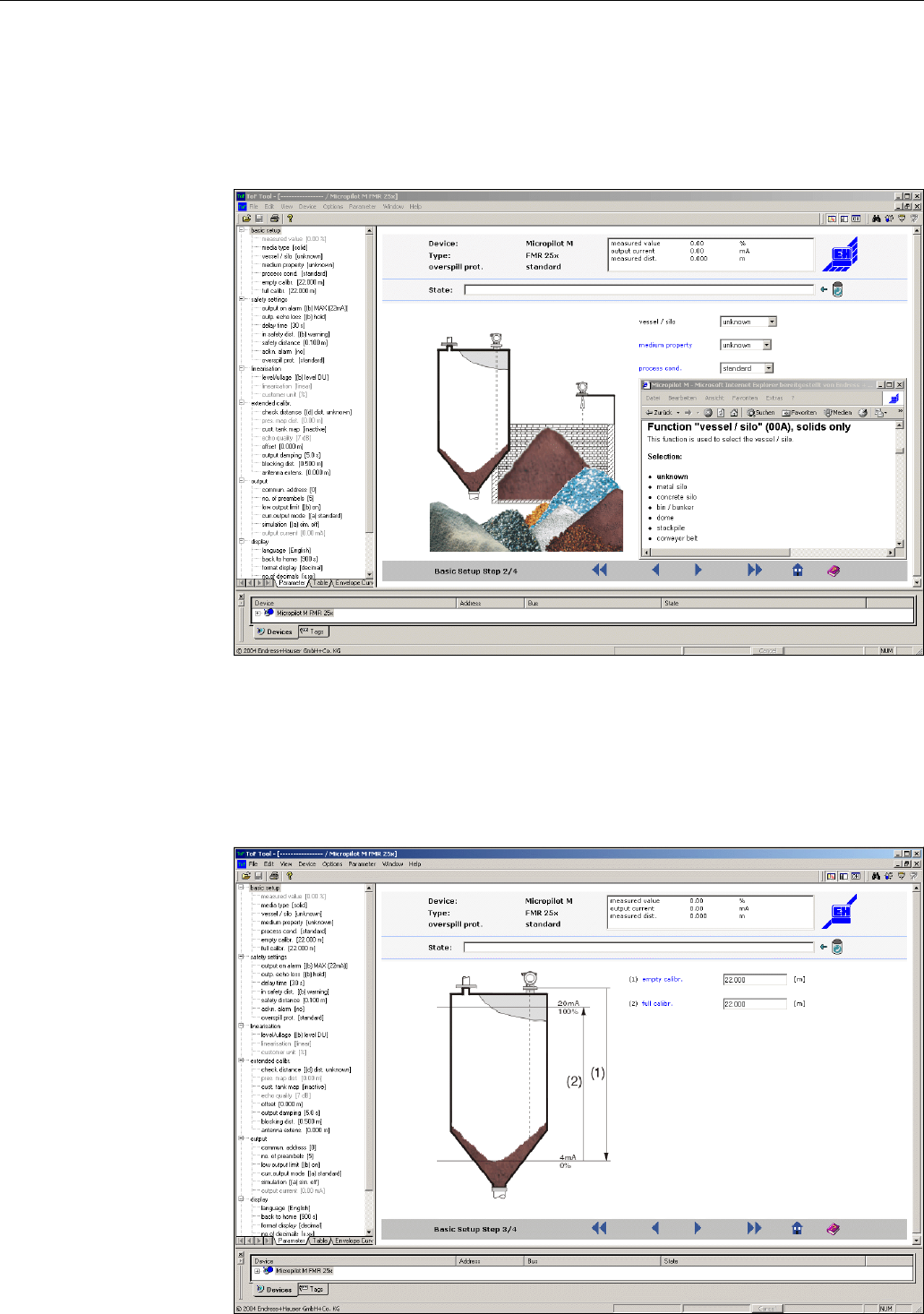
Commissioning Micropilot M FMR250 with HART/4...20 mA
60 Endress + Hauser
Basic Setup step 2/4:
• Enter the application parameters:
– vessel / silo (for a description, see Page 48)
– medium property (for a description, see Page 48)
– process cond. (for a description, see Page 49)
L00-FMR250xx-20-00-00-en-011
Basic Setup step 3/4:
If "metal silo", "concrete silo", "..." is selected in the "vessel / silo" function, the following
display appears on the screen:
• empty calibr. (for a description, see Page 50)
• full calibr.(for a description, see Page 51)
L00-FMR250xx-20-00-00-en-012
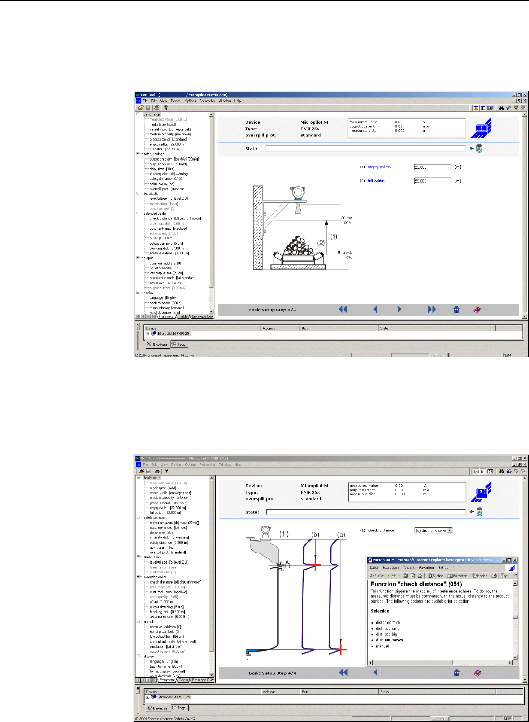
Micropilot M FMR250 with HART/4...20 mA Commissioning
Endress + Hauser 61
If "conveyor belt" is selected in the "vessel / silo" function, the following display appears on the
screen:
• empty calibr. (for a description, see Page 50)
• full calibr.(for a description, see Page 51)
L00-FMR250xx-20-00-00-en-013
Basic Setup step 4/4:
• This step starts the tank mapping
• The measured distance and the current measured value are always displayed in the header
• A description is given on Page 52
L00-FMR250xx-20-00-00-en-014
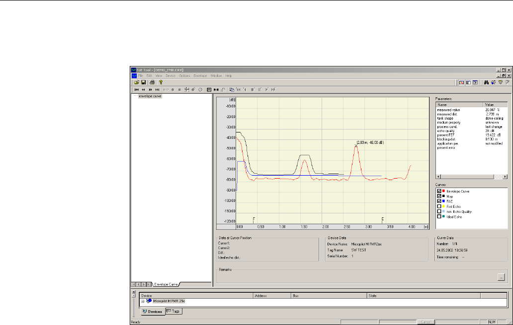
Commissioning Micropilot M FMR250 with HART/4...20 mA
62 Endress + Hauser
6.5.1 Envelope curve with the ToF Tool
After the basic setup, an evaluation of the measurement using the envelope curve is recommended.
L00-FMR250xx-20-00-00-en-008
!Note!
If the level of echo is very weak or there is a heavy interference echo, an orientation of the
Micropilot can help optimise the measurement (increase of the useful echo/reduction of the
interference echo) (see "Orientation of the Micropilot" on Page 73).
When using the Wave Guide antenna: No orientation is required!
6.5.2 User-specific applications (operation)
For details of setting the parameters of user-specific applications, see separate documentation
BA291F/00/en "Description of the instrument functions for Micropilot M" on the enclosed CD-
ROM.

Micropilot M FMR250 with HART/4...20 mA Maintenance
Endress + Hauser 63
7 Maintenance
The Micropilot M measuring instrument requires no special maintenance.
Exterior cleaning
When cleaning the exterior of measuring devices, always use cleaning agents that do not attack the
surface of the housing and the seals.
Replacing seals
The process seals of the sensors must be replaced periodically, particularly if molded seals (aseptic
construction) are used. The period between changes depends on the frequency of cleaning cycles
and on the temperature of the measured substance and the cleaning temperature.
Repairs
The Endress+Hauser repair concept assumes that the measuring devices have a modular design and
that customers are able to undertake repairs themselves. Spare parts are contained in suitable kits.
They contain the related replacement instructions. All the spare parts kits which you can order from
Endress+Hauser for repairs to the Micropilot M are listed with their order numbers on and . Please
contact Endress+Hauser Service for further information on service and spare parts.
Repairs to Ex-approved devices
When carrying out repairs to Ex-approved devices, please note the following:
• Repairs to Ex-approved devices may only be carried out by trained personnel or by
Endress+Hauser Service.
• Comply with the prevailing standards, national Ex-area regulations, safety instructions (XA) and
certificates.
• Only use original spare parts from Endress+Hauser.
• When ordering a spare part, please note the device designation on the nameplate. Only replace
parts with identical parts.
• Carry out repairs according to the instructions. On completion of repairs, carry our the specified
routine test on the device.
• Only Endress+Hauser Service may convert a certified device into a different certified variant.
• Document all repair work and conversions.
Replacement
After a complete Micropilot or electronic module has been replaced, the parameters can be
downloaded into the instrument again via the communication interface. Prerequisite to this is that
the data were uploaded to the PC beforehand using the ToF Tool / FieldCare.
Measurement can continue without having to carry out a new setup.
• You may have to activate linearisation (see BA291F on the enclosed CD-ROM)
• You may need to record the tank map again (see Basic Setup)
After an antenna component or electronic has been replaced, a new calibration must be carried out.
This is described in the repair instructions.
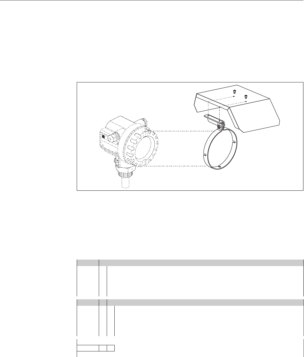
Accessories Micropilot M FMR250 with HART/4...20 mA
64 Endress + Hauser
8 Accessories
Various accessories, which can be ordered separately from Endress+Hauser, are available for the
Micropilot M.
Weather protection cover
A Weather protection cover made of stainless steel is available for outdoor mounting (order code:
543199-0001). The shipment includes the protective cover and tension clamp.
L00-FMR2xxxx-00-00-06-en-001
Service Interface FXA193
The Service-Interface connects the Service plug of Proline and ToF instruments with the 9 pin
RS 232C interface of a PC. (USB connectors must be equipped with a usual commercial USB/Serial
adapter.)
Product structure
Associated documentation
• Technical Information: TI063D
• Safety Instructions for ATEX II (1) GD: XA077D
• Supplementary information for the cable adapters: SD092D
Approvals
A For use in non-hazardous areas
B ATEX II (1) GD
C CSA/FM Class I Div. 1
DATEX, CSA, FM
9other
Connection cable
B Connection cable for ToF devices
E Connection cable for Proline and ToF devices
H Connection cable for Proline and ToF devices and Connection cable for Ex two-wire devices
X without connection cable
9others
FXA193- Complete product designation
ENDRESS+HAUSER
MICROPILOT II
ENDRESS+HAUSER
MICROPILOT II
IP 65
IP 65
Order Code:
Ser.-No.:
Order Code:
Ser.-No.:
Messbereich
Measuring range
Messbereich
Measuring range
U 16...36V DC
4...20 mA
U 16...36 V DC
4...20 mA
max.20 m
max. 20 m
Made in Germany Maulburg
T>
70°C :
At >85°C
T>70°C :
At >85°C
F12 / F23 / T12 housing
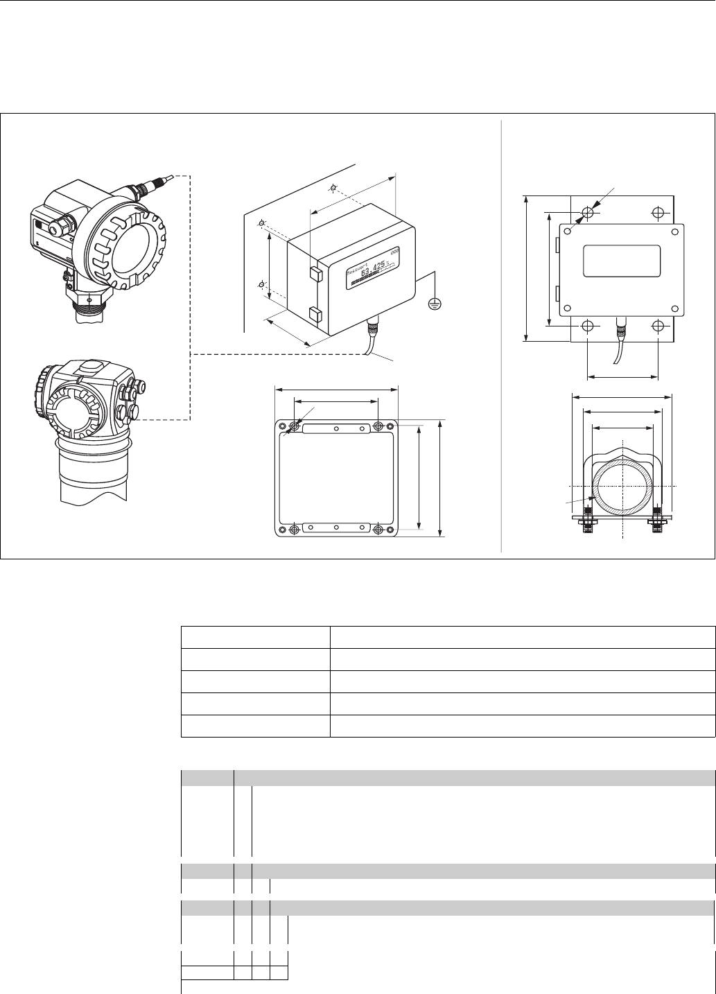
Micropilot M FMR250 with HART/4...20 mA Accessories
Endress + Hauser 65
Remote display FHX40
Dimensions
L00-FMxxxxxx-00-00-06-en-003
Technical data and product structure:
ENDRESS+HAUSER
ENDRESS+HAUSER
IP 65
Order Code:
Ser.-No.:
Order Code:
Ser.-No.:
Messbereich
Measuring range
Messbereich
Measuring range
U 16...36V DC
4...20 mA
U 16...36 V DC
4...20 mA
max.20 m
max. 20 m
Made in Germany Maulburg
Made in Germany Maulburg
T>
70°C :
At >85°C
T>70°C :
At >85°C
82
6,3
106
122
120
max. 80
min. 30
96
88
160
8,5
118
180
Micropilot M
Levelflex M
Prosonic M
Gammapilot M
Separate housing
FHX 40 (IP 65)
Cable
H
W
D
Wall-mounting
(without mounting bracket)
Pipe-mounting
(mounting bracket and plate
supplied optionally,
s. product structure)
pipe
Max. cable length 20 m (65 ft)
Temperature range -30 °C...+70 °C (-22 °F...158 °F)
Degree of protection IP65 acc. to EN 60529 (NEMA 4)
Material for housing Alloy of Aluminium AL Si 12
Dimensions [mm] / [inch] 122x150x80 (HxWxD) / 4.8x5.9x3.2
Approval:
A Nn-hazardous area
1 ATEX II 2 G EEx ia IIC T6, ATEX II 3D
S FM IS Cl.I Div.1 Gr.A-D
U CSA IS Cl.I Div.1 Gr.A-D
N CSA General Purpose
Cable length:
1 20m/65ft
Additional option:
A Basic version
B Mounting bracket, pipe 1"/ 2"
FHX40 - Complete product designation
Trouble-shooting Micropilot M FMR250 with HART/4...20 mA
66 Endress + Hauser
9 Trouble-shooting
9.1 Trouble-shooting instructions
L00-FMR250xx-19-00-00-en-003
Instrument does
not respond
Check voltage and
compare it with the
specifications on the
nameplate.
Connect the
correct voltage Instrument works? Ready
Check the polarity
of the voltage.
Check power connection
to electronic board
Correct the polarity
Connect plug
Instrument works?
Instrument works?
Ready
Ready
Values on display
invisible
ok
ok
ok
Yes
Yes
Yes
No
No
No
No
Not ok
Not ok
Not ok
Check plug contact
of the display.
Connect the plug
correctly
Correct configuration
Display works? Ready
Ready
Yes
ok
No
Not ok
Yes
No
Micropilot M FMR 250 -Trouble Shooting
ok
Output current between
3.6 …22mA ?
Contrast: FO+
The display is possibly defective.
Contact E+H Service
Yes
Output current
< 3,6 mA ?
No
Check cabling Correct the
cabling Current is ok? Ready
Yes
No
Possibly defective electronics
Contact E+H Service
HART
communication
does not
function
Is the communication
resistor installed
according to the
OM?
Install the resistor
(see the OM) Communication ok? Ready
Ready
ok
Yes
Yes
No
No
Connect the
Commubox
(see the OM)
Communication ok? Ready
Set the switch
correctly Communication ok Ready
Ready
Contact E+H Service
Contact E+H Service
ok
ok
ok
Yes
No
Yes
Yes
No
ok
Not ok
Not ok
Not ok
Not ok
Not ok
Not ok
?
Is the switch on the
Commubox for
selecting HART/Intensor
in the correct position?
Is the Commubox
connected according
to the OM?
Communication
via Service adapter
FXA 193 does not
function
Instrument
measures
incorrectly
Check configuration
of COM port on PC
Check basic setup
Proceed according
to section
'Trouble shooting’in OM
Repeat
basic setup
Not ok
Yes
Yes
Yes
Yes
Communication ok?
Measurement ok?

Micropilot M FMR250 with HART/4...20 mA Trouble-shooting
Endress + Hauser 67
9.2 System error messages
Code Description Possible cause Remedy
A102 checksum error
general reset & new
calibr.required
device has been powered off before data
could be stored;
emc problem;
E2PROM defect
reset;
avoid emc problem;
if alarm prevails after reset,
exchange electronics
W103 initialising - please wait E2PROM storage not yet finished wait some seconds; if warning
prevails, exchange electronics
A106 downloading please wait processing data download wait until warning disappears
A110 checksum error
general reset & new
calibr.required
device has been powered off before data
could be stored;
emc problem;
E2PROM defect
reset;
avoid emc problem;
if alarm prevails after reset,
exchange electronics
A111 electronics defect RAM defective reset;
if alarm prevails after reset,
exchange electronics
A113 electronics defect RAM defective reset;
if alarm prevails after reset,
exchange electronics
A114 electronics defect E2PROM defect reset;
if alarm prevails after reset,
exchange electronics
A115 electronics defect general hardware problem reset;
if alarm prevails after reset,
exchange electronics
A116 download error
repeat download
checksum of stored data not correct restart download of data
A121 electronics defect no factory calibration existant;
EPROM defective
contact service
W153 initialising - please wait initialisation of electronics wait some seconds; if warning
prevails, power off device and
power on again
A155 electronics defect hardware problem reset;
if alarm prevails after reset,
exchange electronics
A160 checksum error
general reset & new
calibr.required
device has been powered off before data
could be stored;
emc problem;
E2PROM defect
reset;
avoid emc problem;
if alarm prevails after reset,
exchange electronics
A164 electronics defect hardware problem reset;
if alarm prevails after reset,
exchange electronics
A171 electronics defect hardware problem reset;
if alarm prevails after reset,
exchange electronics
A231 sensor 1 defect
check connection
HF module or electronics defective exchange HF module or electronics
W511 no factory calibration ch1 factory calibration has been deleted record new factory calibration
A512 recording of mapping please
wait
mapping active wait some seconds until alarm
disappears
A601 linearisation ch1 curve not
monotone
linearisation not monotonously increasing correct linearisation table
W611 less than 2 linearisation
points for channel 1
number of entered linearisation points < 2 correct linearisation table
W621 simulation ch. 1 on simulation mode is active switch off simulation mode

Trouble-shooting Micropilot M FMR250 with HART/4...20 mA
68 Endress + Hauser
E641 no usable echo
channel 1
check calibr.
echo lost due to application conditions or
built up on antenna
check installation;
optimize orientation of antenna;
clean antenna (cf. OM)
E651 level in safety distance - risk
of overspill
level in safety distance alarm will disappear as soon as level
leaves safety distance;
E671 linearisation ch1 not
complete, not usable
linearisation table is in edit mode activate linearisation table
W681 current ch1 out of range current out of range (3.8 mA...21.5 mA) check calibration and linearisation
Code Description Possible cause Remedy
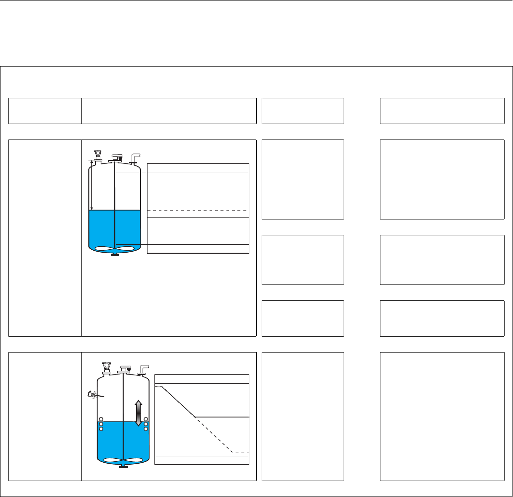
Micropilot M FMR250 with HART/4...20 mA Trouble-shooting
Endress + Hauser 69
9.3 Application errors in liquids
Error Output Possible cause Remedy
A warning or alarm
has occurred.
Depending on the configuration See table of error
messages (see Page 67)
1. See table of error messages
(see Page 67)
Measured value
(00) is incorrect
L00-FMR2xxxx-19-00-00-en-019
Measured distance
(008) OK?
yes →1. Check empty calibr. (005) and
full calibr. (006).
2. Check linearisation:
→ level/ullage (040)
→ max. scale (046)
→ diameter vessel (047)
→ Check table
no ↓
Measurement in bypass
or stilling well?
yes →1. Is bypass or stilling well selected
in tank shape (002)?
2. Is the pipe diameter (007)
correct?
no ↓
An interference echo
may have been
evaluated.
yes →1. Carry out tank mapping
→ basic setup
No change off
measured value on
filling/emptying
L00-FMR2xxxx-19-00-00-en-014
Interference echo from
installations, nozzle or
extension on the
antenna
1. Carry out tank mapping
→ basic setup
2. If necessary, clean antenna
3. If necessary, select better
mounting position
100%
F m/ft
E m/ft
0% t →
D m/ft (008)
actual
expected
100%
0% t →
actual
expected
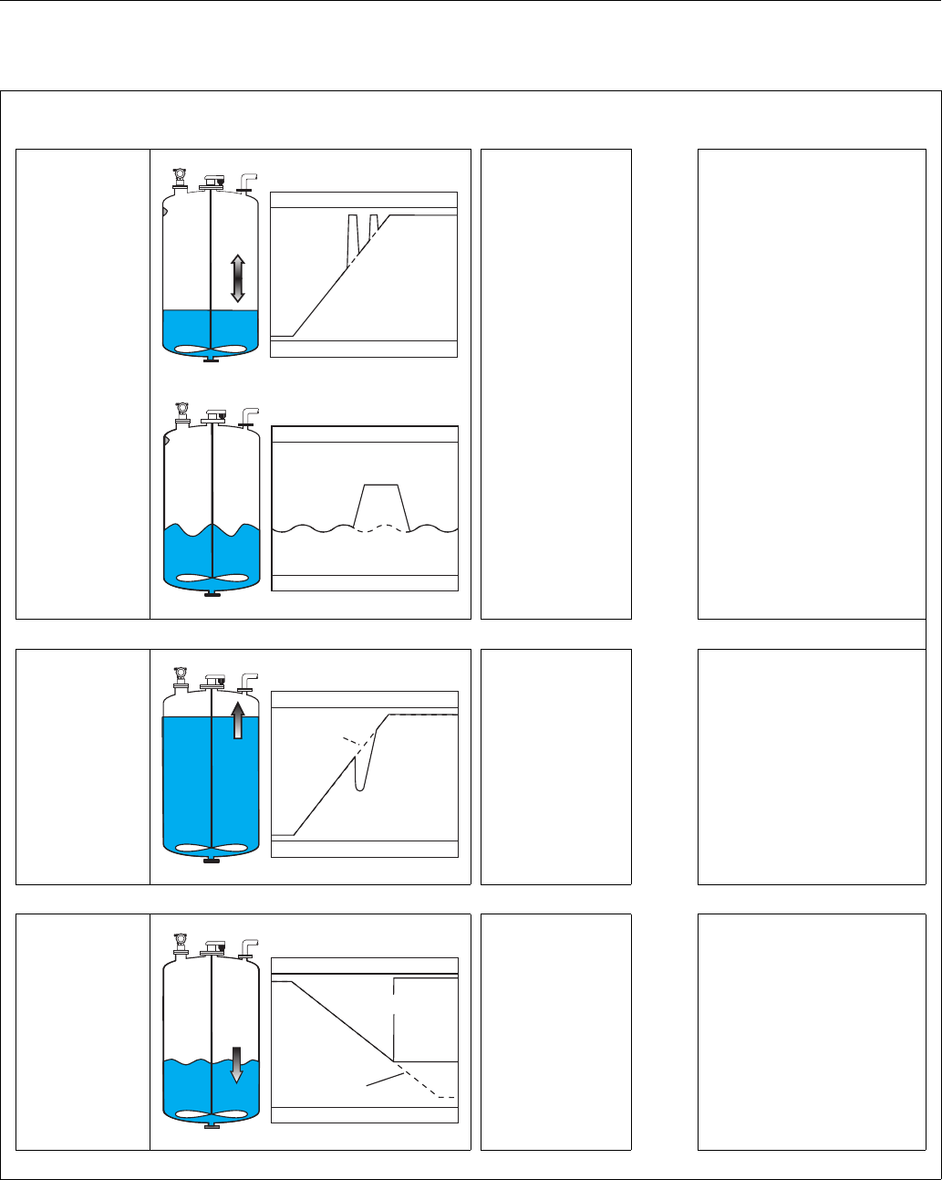
Trouble-shooting Micropilot M FMR250 with HART/4...20 mA
70 Endress + Hauser
Error Output Possible cause Remedy
If the surface is not
calm (e.g. filling,
emptying, agitator
running), the
measured value
jumps sporadically
to a higher level
L00-FMR2xxxx-19-00-00-en-015
L00-FMR2xxxx-19-00-00-en-016
Signal is weakened by
the rough surface – the
interference echoes are
sometimes stronger
1. Carry out tank mapping → basic
setup
2. Set the process cond. (004) to
"turb. surface" or "agitator"
3. Increase the output damping
(058)
4. Optimise the orientation
(see Page 73)
5. If necessary, select a better
mounting position and/or larger
antenna
During filling/
emptying the
measured value
jumps ownwards
L00-FMR2xxxx-19-00-00-en-017
Multiple echoes yes →1. Check the tank shape (002), e.g.
"dome ceiling" or "horizontal
cyl"
2. In the range of the blocking dist.
(059) there is no echo evaluation
→ Adapt the value
3. If possible, do not select central
installation position
4. Perhaps use a stilling well
E 641 (loss of
echo)
L00-FMR2xxxx-19-00-00-en-018
Level echo is too weak.
Possible causes:
• Rough surface due to
filling/ emptying
• Agitator running
•Foam
yes →1. Check application arameters
(002), (003) and (004)
2. Optimise alignment
(see Page 73)
3. If necessary, select a better
installation position and/or larger
antenna
100%
0% t →
actual
expected
100%
0% t →
actual
expected
100%
0% t →
actual
expected
100%
E 641
0% t →
eingetreten
erwartet
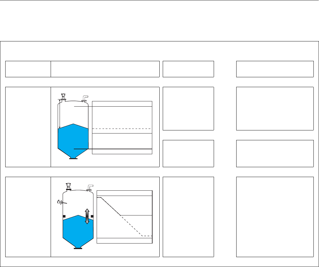
Micropilot M FMR250 with HART/4...20 mA Trouble-shooting
Endress + Hauser 71
9.4 Application errors in solids
Error Output Possible cause Remedy
A warning or alarm
has occurred.
Depending on the configuration See table of error
messages (see Page 67)
1. See table of error messages
(see Page 67)
Measured value
(00) is incorrect
L00-FMR250xx-19-00-00-en-019
Measured distance
(008) OK?
yes →1. Check empty calibr. (005) and
full calibr. (006).
2. Check linearisation:
→ level/ullage (040)
→ max. scale (046)
→ Check table
no ↓
An interference echo
may have been
evaluated.
yes →1. Carry out tank mapping
→ basic setup
No change off
measured value on
filling/emptying
L00-FMR250xx-19-00-00-en-014
Interference echo from
installations, nozzle or
build up on the antenna
1. Carry out tank mapping
→ basic setup
2. If necessary, use top target
positioner to aim antenna better
to product surface (avoidance of
interference echo) (see Page 73)
3. If necessary, clean antenna (air
purge)
4. If necessary, select better
mounting position
100%
F m/ft
E m/ft
0% t →
D m/ft (008)
actual
expected
100%
0% t →
actual
expected
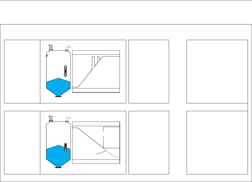
Trouble-shooting Micropilot M FMR250 with HART/4...20 mA
72 Endress + Hauser
Error Output Possible cause Remedy
During filling or
emptying the
measured value
jumps sporadically
to a higher level
L00-FMR250xx-19-00-00-en-015
Signal is weakened (e.g.
by fluidisation of the
surface, extreme dust
formation) – the
interference echoes are
sometimes stronger
1. Carry out tank mapping → basic
setup
2. Increase the output damping
(058)
3. Optimise the orientation
(see Page 73)
4. If necessary, select a better
mounting position and/or larger
antenna
E 641 (loss of
echo)
L00-FMR250xx-19-00-00-en-018
Level echo is too weak.
Possible causes:
• fluidisation of the
surface
• extreme dust
formation
• angle of repose
yes →1. Check application arameters
(00A), (00B) and (00C)
2. Optimise alignment
(see Page 73)
3. If necessary, select a better
installation position and/or larger
antenna
100%
0% t →
actual
expected
100%
E 641
0% t →
actual
expected
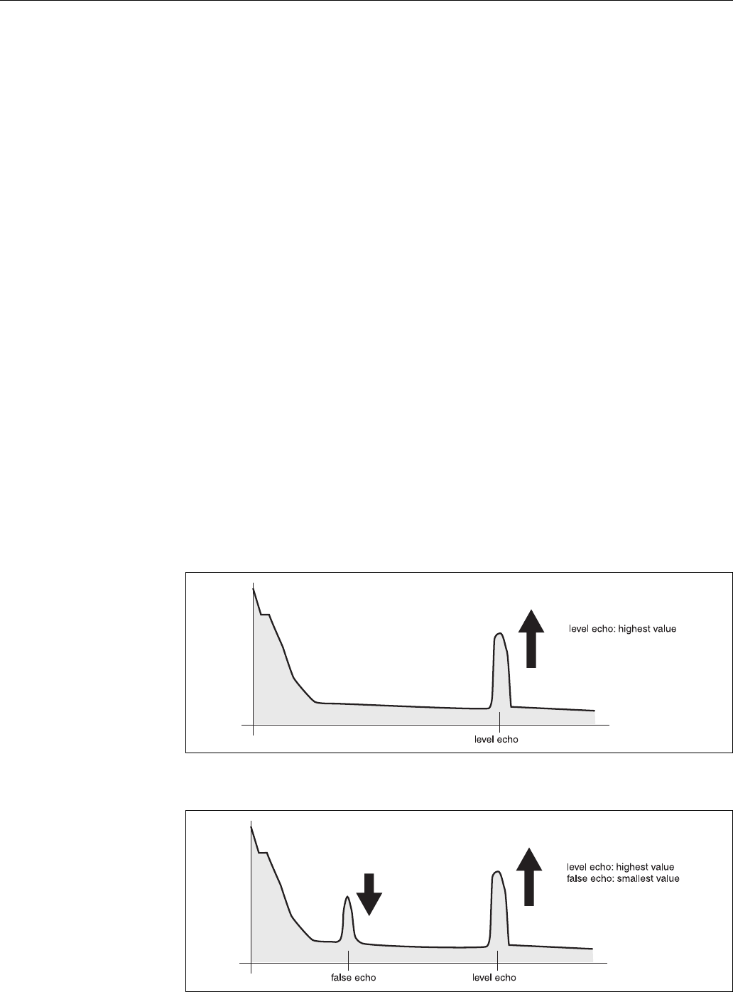
Micropilot M FMR250 with HART/4...20 mA Trouble-shooting
Endress + Hauser 73
9.5 Orientation of the Micropilot
For orientation a marker is found on the flange or threaded boss of the Micropilot. During
installation this must be oriented as follows (see Page 11):
• In tanks: to the vessel wall
• In stilling wells: to the slots
• In bypass pipes: vertical to the tank connectors
• When using the Wave Guide antenna no orientation is required!
After commissioning the Micropilot, the echo quality indicates whether a sufficiently large
measuring signal is obtained. If necessary, the quality can be optimised later. Vice versa, the
presence of an interference echo can be used to minimise this by optimum orientation. The
advantage of this is that the subsequent tank mapping uses a somewhat lower level that causes an
increase in the strength of the measuring signal.
Proceed as follows:
#Warning!
Subsequent alignment can lead to personal injury. Before you unscrew or loosen the process
connection, make sure that the vessel is not under pressure and does not contain any injurious
substances.
1. It is best to empty the container so that the bottom is just covered. However, alignment can be
carried out even if the vessel is empty.
2. Optimisation is best carried out with the aid of the envelope graph in the display or the
ToF Tool.
3. Unscrew the flange or loosen the threaded boss by a half a turn.
4. Turn the flange by one hole or screw the threaded boss by one eighth of a turn. Note the echo
quality.
5. Continue to turn until 360° is reached.
6. Optimum alignment:
L00-FMRxxxxx-19-00-00-en-002
Fig. 5: Vessel partly full, no interference echo obtained
L00-FMRxxxxx-19-00-00-en-003
Fig. 6: Vessel partly full, interference echo obtained:
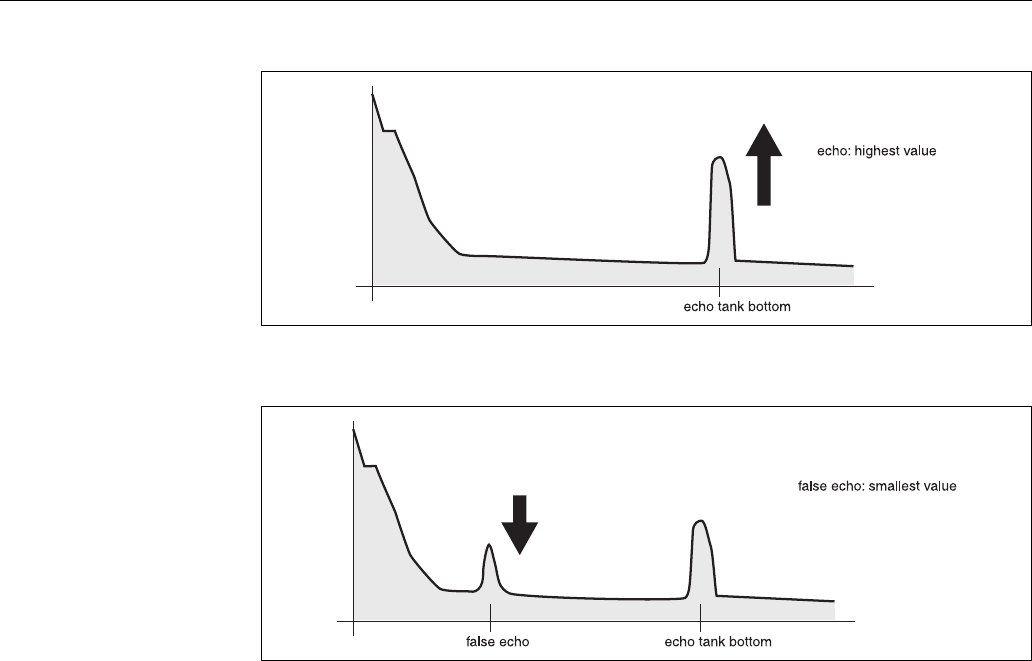
Trouble-shooting Micropilot M FMR250 with HART/4...20 mA
74 Endress + Hauser
L00-FMRxxxxx-19-00-00-en-004
Fig. 7: Vessel empty, no interference echo
L00-FMRxxxxx-19-00-00-en-005
Fig. 8: Vessel empty, interference echo obtained
7. Fix the flange or threaded boss in this position.
If necessary, replace the seal.
8. Carry out tank mapping, see Page 53.
Top target positioner - optional
Using top target positioner it is possible to tilt the antenna axis by up to 15° in all directions. The
top target positioner is used for the optimum alignment of the radar beam with the bulk solids
surface.
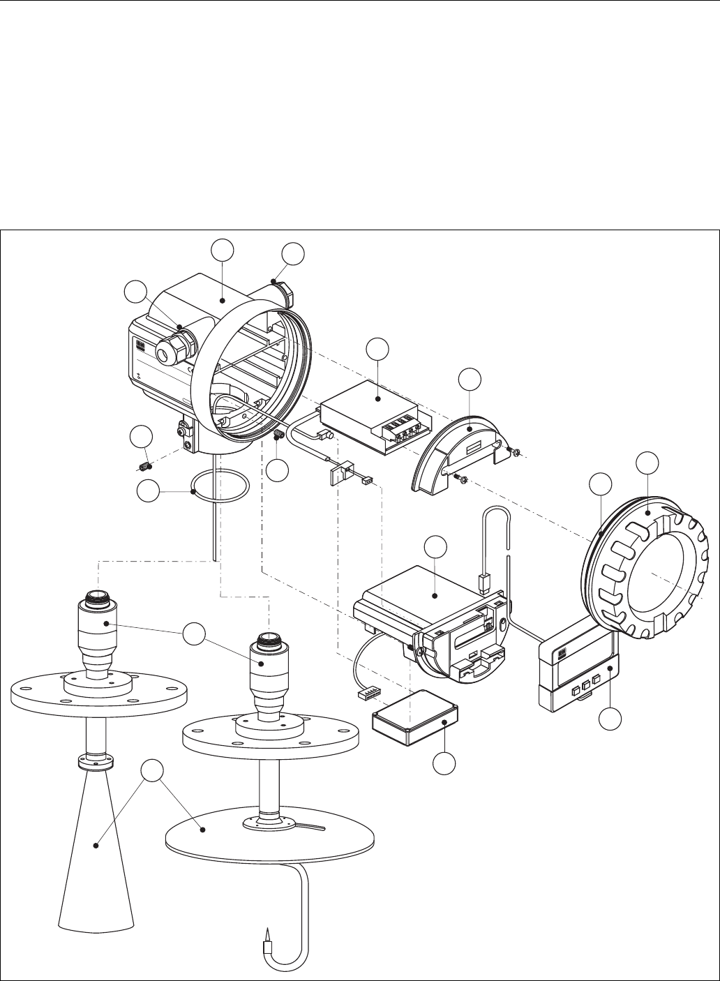
Micropilot M FMR250 with HART/4...20 mA Trouble-shooting
Endress + Hauser 75
9.6 Spare parts
!Note!
You can order spare parts directly from your E+H service organization by giving the serial number
which is printed on the measuring transducer nameplate (see Page 8s. Seite 8 ff.). The
corresponding spare part number also appears on each spare part. Installation instructions are given
on the instruction card that is also delivered.
Spare parts Micropilot M FMR250, F12 housing with combined wiring and electronics
compartment
L00-FMR250xx-00-00-06-xx-001
65
ENDRESS+HAUSER
MICROPILOT II
IP 65
Order Code:
Ser.-No.:
Messbereich
Measuring range
U 16...36V DC
4...20 mA
max. 20 m
Made in Germany Maulburg
Made in Germany Maulburg
T>70
°C :
At >85°C
1234
Te rminal
ENDRESS+HAUSER
10 65
65
11
65
35
30
40
31
12
12
20
50
55

Trouble-shooting Micropilot M FMR250 with HART/4...20 mA
76 Endress + Hauser
10 Housing - for E+H service only!
543120-0022 Housing F12, Aluminium, G1/2
543120-0023 Housing F12, Aluminium, NPT1/2
543120-0024 Housing F12, Aluminium, M20
11 Hood for terminal compartment
52006026 Cover terminal compartment F12
52019062 Hood terminal compartment F12, FHX40
12 Screw set
535720-9020 Set of screws housing F12/T12
20 Cover
52005936 Cover F12/T12 Aluminium, window, gasket
517391-0011 Cover F12/T12 Aluminium, coated, gasket
30 Electronics
52024952 Electronics FMR250, Ex, HART
31 HF module
52024953 HF module FMR250, 26 GHz
35 Terminal module / power supply board
52006197 Terminal module 4pole, HART, 2-wire with cable connection
40 Display
52005585 Display VU331
50 Antenna assembly with process connection on request!
55 Horn antenna
52025230 Horn FMR250 80mm/3", VA
52025231 Horn FMR250 100mm/4", VA
55 Parabolic antenna
52025233 Parabolic reflector 197x25, 316L
65 Sealing kit
535720-9010 consists of:
2 x gasket Pg13.5 FA
2 x O-ring 17.0x2.0 EPDM
1 x O-ring 49.21x3.53 EPDM
2 x O-ring 17.12x2.62 FKM
1 x O-ring 113.9x3.63 EPDM
1 x O-ring 72.0x3.0 EPDM
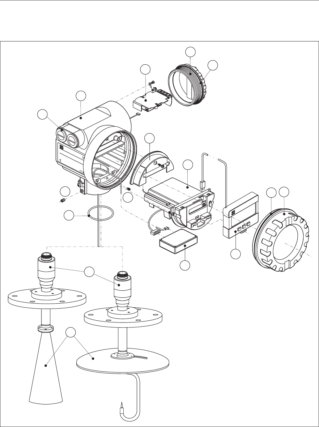
Micropilot M FMR250 with HART/4...20 mA Trouble-shooting
Endress + Hauser 77
Spare parts Micropilot M FMR250, T12 housing with separate wiring and electronics
compartment
L00-FMR250xx-00-00-06-xx-002
ENDRESS+HAUSER
MICROPILOT FMR
IP 65
Order Code:
Ser.-No.:
Messbereich
Measuring range
U 16...36V DC
4...20 mA
max.20 m
Made in Germany Maulburg
T>
70°C :
At >85°C
ENDRESS+HAUSER
ENDRESS+HAUSER
10
65
65
25
65
11
30
35
40
31
12
12 20
65
50
55

Trouble-shooting Micropilot M FMR250 with HART/4...20 mA
78 Endress + Hauser
10 Housing - for E+H service only!
543180-0022 Housing T12, Aluminium, coated, G1/2, PAL
543180-0023 Housing T12, Aluminium, coated, NPT1/2, PAL
543180-0024 Housing T12, Aluminium, coated, M20, PAL
543180-1023 Housing T12, Aluminium, NPT1/2, PAL, cover, EEx d
52006204 Housing T12, Aluminium, G1/2, PAL, cover, EEx d
52006205 Housing T12, Aluminium, M20, PAL, cover, EEx d
11 Hood for terminal compartment
52005643 Hood T12
12 Screw set
535720-9020 Set of screws housing F12/T12
20 Cover
52005936 Cover F12/T12 Aluminium, window, gasket
517391-0011 Cover F12/T12 Aluminium, coated, gasket
25 Cover for terminal compartment
518710-0020 Cover T3/T12, Aluminium, coated, gasket
30 Electronics
52024952 Electronics FMR250, Ex, HART
31 HF module
52024953 HF module FMR250, 26 GHz
35 Terminal module / power supply board
52013302 Terminal module 4pole, 2-wire, HART, EEx d
52018949 Terminal module 4pole, 2-wire, HART, EEx ia, overvoltage protection
40 Display
52005585 Display VU331
50 Antenna assembly with process connection on request!
55 Horn antenna
52025230 Horn FMR250 80mm/3", VA
52025231 Horn FMR250 100mm/4", VA
55 Parabolic antenna
52025233 Parabolic reflector 197x25, 316L

Micropilot M FMR250 with HART/4...20 mA Trouble-shooting
Endress + Hauser 79
65 Sealing kit
535720-9010 consists of:
2 x gasket Pg13.5 FA
2 x O-ring 17.0x2.0 EPDM
1 x O-ring 49.21x3.53 EPDM
2 x O-ring 17.12x2.62 FKM
1 x O-ring 113.9x3.63 EPDM
1 x O-ring 72.0x3.0 EPDM

Trouble-shooting Micropilot M FMR250 with HART/4...20 mA
80 Endress + Hauser
Spare parts Micropilot M FMR250, F23 housing with combined wiring and electrinics
compartment
Stainless steel housing on request!
20 Cover
52018670 Cover F23, 316L, sight glass, gasket
52018671 DeCoverckel F23, 316L, gasket

Micropilot M FMR250 with HART/4...20 mA Trouble-shooting
Endress + Hauser 81
9.7 Return
The following procedures must be carried out before a transmitter is sent to Endress+Hauser e.g.
for repair or calibration:
• Remove all residue which may be present. Pay special attention to the gasket grooves and crevices
where fluid may be present. This is especially important if the fluid is dangerous to health, e.g.
corrosive, poisonous, carcinogenic, radioactive, etc.
• Always enclose a duly completed "Declaration of contamination" form (a copy of the “Declaration
of contamination” is included at the end of this operating manual). Only then can Endress
+Hauser transport, examine and repair a returned device.
• Enclose special handling instructions if necessary, for example a safety data sheet as per EN 91/
155/EEC.
Additionally specify:
• An exact description of the application.
• The chemical and physical characteristics of the product.
• A short description of the error that occurred (specify error code if possible)
• Operating time of the device.
9.8 Disposal
In case of disposal please seperate the different components according to their material consistence.
9.9 Software history
9.10 Contact addresses of Endress+Hauser
The addresses of Endress+Hauser are given on the back cover of this operating manual. If you have
any questions, please do not hesitate to contact your E+H representative.
Software version /
Date
Software changes Documentation changes
V 01.01.00 / 09.2004 Original software.
Operated via:
– ToF Tool from version 2.0
– HART communicator DXR375
with Rev. 1, DD 1.

Technical data Micropilot M FMR250 with HART/4...20 mA
82 Endress + Hauser
10 Technical data
10.1 Additional technical data
10.1.1 Input
Measured variable The measured variable is the distance between a reference point and a reflective surface (i.e.
medium surface).
The level is calculated based on the tank height entered.
The level can be converted into other units (volume, mass) by means of a linearization.
10.1.2 Output
Output signal 4…20 mA with HART protocol
Signal on alarm Error information can be accessed via the following interfaces:
•Local display:
– Error symbol (see Page 34)
– Plain text display
• Current output
• Digital interface
Linearization The linearization function of the Micropilot M allows the conversion of the measured value into any
unit of length or volume. Linearization tables for calculating the volume in cylindrical tanks are pre-
programmed. Other tables of up to 32 value pairs can be entered manually or semi-automatically.
10.1.3 Auxiliary energy
Ripple HART 47...125 Hz: Uss = 200 mV (at 500 Ω)
Max. noise HART 500 Hz...10 kHz: Ueff = 2.2 mV (at 500 Ω)
10.1.4 Performance characteristics
Reference operating
conditions
• temperature = +20 °C (68 °F) ±5 °C (9 °F)
• pressure = 1013 mbar abs. (14.7 psia) ±20 mbar (0.3 psi)
• relative humidity (air) = 65 % ±20%
•ideal reflector
• no major interference reflections inside the signal beam
Maximum measured error Typical statements for reference conditions, include linearity, repeatability, and hysteresis:
• up to 1 m: ±30 mm
• ex 1 m: ±15 mm (or 0.04% of measuring range, whatever is larger)
Resolution Digital / analog in % 4…20 mA
• FMR250: 1mm / 0.03 % of measuring range
Reaction time The reaction time depends on the parameter settings (min. 1 s). In case of fast level changes, the
instrument needs the reaction time to indicate the new value.

Micropilot M FMR250 with HART/4...20 mA Technical data
Endress + Hauser 83
Influence of ambiente
temperature
The measurements are carried out in accordance with EN 61298-3:
• digital output (HART):
–FMR250
average TK: 5 mm/10 K, max. 15 mm over the entire temperature range -40 °C...+80 °C
• Current output (additional error, in reference to the span of 16 mA):
–Zero point (4 mA)
average TK: 0,03 %/10 K, max. 0,45 % over the entire temperature range -40 °C...+80 °C
–Span (20 mA)
average TK: 0,09 %/10 K, max. 0,95 % over the entire temperature range -40 °C...+80 °C
10.1.5 Operating conditions: Environment
Ambient temperature range Ambient temperature for the transmitter: -40 °C ... +80 °C (-40 °F … +176 °F), -50 °C
(-58 °F) on request.
The functionality of the LCD display may be limited for temperatures
Ta<-20 °C and Ta>+60 °C.
A weather protection cover should be used for outdoor operation if the instrument is exposed to
direct sunlight.
Storage temperature -40 °C … +80 °C (-40 °F … +176°F), -50 °C (-58 °F) on request.
Climate class DIN EN 60068-2-38 (test Z/AD)
Vibration resistance DIN EN 60068-2-64 / IEC 68-2-64: 20…2000 Hz, 1 (m/s2)2/Hz
Cleaning of the antenna The antenna can get contaminated, depending on the application. The emission and reception of
microwaves can thus eventually be hindered. The degree of contamination leading to an error
depends on the medium and the reflectivity, mainly determined by the dielectric constant εr. If the
medium tends to cause contamination and deposits, cleaning on a regular basis is recommended.
Care has to be taken not to damage the antenna in the process of a mechanical or hose-down
cleaning (eventually air purge connection). The material compatibility has to be considered if
cleaning agents are used!
The maximum permitted temperature at the flange should not be exceeded.
Electromagnetic compatibility • Interference Emission to EN 61326, Electrical Equipment Class B
• Interference Immunity to EN 61326, Annex A (Industrial) and NAMUR Recommendation
NE 21 (EMC)
• A standard installation cable is sufficient if only the analogue signal is used. Use a screened cable
when working with a superimposed communications signal (HART).

Technical data Micropilot M FMR250 with HART/4...20 mA
84 Endress + Hauser
10.1.6 Operating conditions: Process
Dielectric constant • in free space: εr ≥ 1.6
10.1.7 Mechanical construction
Weight • F12/T12 housing: approx 6 kg + weight of flange
• F23 housing: approx 9.4 kg + weight of flange
10.1.8 Certificates and approvals
CE approval The measuring system meets the legal requirements of the EC-guidelines. Endress+Hauser confirms
the instrument passing the required tests by attaching the CE-mark.
RF approvals R&TTE, FCC
External standards and
guidelines
EN 60529
Protection class of housing (IP-code)
EN 61010
Safety regulations for electrical devices for measurement, control, regulation and laboratory use.
EN 61326
Emissions (equipment class B), compatibility (appendix A - industrial area)
NAMUR
Standards committee for measurement and control in the chemical industry
Ex approval Correlation of safety instructions (XA) and certificates (ZE) to the instrument:
Seal / Temperature E FKM Viton GLT, -40 °C...+200 °C (-40 °F...+392 °F)
Pressure -1 ...16 bar (...232 psi), E+H UNI flange: -1...1 bar (...14.5 psi)
Antenna cone PEEK
Wetted parts PEEK, seal and 316 L/1.4404/1.4435
Optional: top target positioner ±15°, seal: FKM Viton GLT
Instrument Certificate Explosion protection Output Communication Housing PTB 04 ATEX XA
FMR250 A Non-hazardous area A, B, K HART — — —
1 ATEX II 1/2G EEx ia IIC T6 A, B, K HART A, B, D in preparation XA313F-A
4 ATEX II 1/2G EEx d [ia] IIC T6 A, B, K HART C in preparation XA314F-A
G ATEX II 3G EEx nA II T6 A, B, K HART in preparation
B ATEX II 1/2GD EEx ia IIC T6, Alu blind cover A, B, K HART A, B, D in preparation XA312F-A
C ATEX II 1/2G EEx ia IIC T6
ATEX II 1/3D
A, B, K HART A, B, D in preparation XA312F-A
D ATEX II 1/2D, Alu blind cover A, B, K HART C in preparation XA315F-A
E ATEX II 1/3D A, B, K HART C in preparation XA315F-A

Micropilot M FMR250 with HART/4...20 mA Technical data
Endress + Hauser 85
Control Drawings Correlation of Control Drawings (ZD) to the instrument:
10.1.9 Supplementary Documentation
Supplementary
Documentation
• Technical Information (TI390F/00/en)
• Operating Instructions "Description of instrument functions" (BA291F/00/en)
Instrument Certificate Explosion protection Output Communication Housing ZD
FMR250 S FM IS A, B, K HART A, B, D ZD168F/00/en
T FM XP A, B, K HART C ZD169F/00/en
U CSA IS A, B, K HART A, B, D ZD170F/00/en
V CSA XP A, B, K HART C ZD171F/00/en
Appendix Micropilot M FMR250 with HART/4...20 mA
86 Endress + Hauser
11 Appendix
11.1 Operating menu HART (display modul), ToF Tool
L00-FMR250xx-19-00-01-en-036
safety settings
basic setup
output on alarm
MIN -10% 3.6mA
hold
MAX 110% 22mA
tank shape
vessel / silo
media type
dome ceiling
horizontal cyl.
unknown
metal silo
concrete silo
bin / bunker
dome
stockpile
conveyor belt
liquid
solid bypass
stilling well
flat ceiling
sphere
level/ullage
level DU
ullage DU
level CU
ullage CU
selection
mapping
common
extended map..
commun. address
present error
tag no.
fixed cur. value
4mA value 20mA value
enter value
medium cond.
medium cond.
unknown
DK: < 1.9
DK: 1.9 … 4
DK: 4 … 10
DK: > 10
unknown
DC: 1.6 ... 1.9
DC: 1.9 … 2.5
DC: 2.5 … 4
DC: 4 … 7
DC: > 7
linearisation
manual
semi-automatic
table on
horicontal cyl
linear
clear table
dist./meas value
D and L
are displayed
no. of preambels
language
previous error
outp. echo loss
alarm
hold
ramp %MB/min
process cond.
process cond.
standard
calm surface
turb. surface
add. agitator
fast change
test: no filter
standard
fast change
slow change
test: no filter
customer unit
table no.
input level
input volume
customer unit
customer unit
check distance
distance = ok
dist. too small
manual
dist. unknown
dist. too big
low output limit
off
on
back to home
enter time
default: 100 s
clear last error
protocol+sw-no.
plot settings
envelope curve
env.curve+FAC
env.curve+cust.map
ramp %span/min
empty calibr.
empty calibr.
enter value
enter value
linearisation
range of mapping
pres. Map dist
input of
mapping range
is displayed
curr. output mode
format display
decimal
reset
for reset code
see manual
recording curve
single curve
cyclic
Note! The default values of the parameters are typed in boldface.
delay time
in case of echo loss
max. 4000 sec.
default: 30 s
full calibr.
full calibr.
enter value
enter value
next point
yes
no
start mapping
cust. Tank map
off
on
inactive
active
reset
no. of decimals
x
x.x
x.xx
x.xxx
unlock parameter
for reset code
see manual
serial no.
linearisation
extended calibr.
output
envelope curve
display
diagnostics
system parameter
01
00
010
002
00A
001
040
040
040
050
060
0A0
0C0
003
00B
041
041
008
061
092
0A1
012
004
00C
042
043
044
045
042
042
051
062
093
0A2
0C2
0E1
013
005
005
052
054
063
094
0A3
0E2
014
006
006
045
053
055
064
068 069
095
0A4
0C4
04
05
06
0E
09
0A
0C
1/16”
user specific output on alarm
enter value
011
standard
fixed current
fixed current
Micropilot M FMR250 with HART/4...20 mA Appendix
Endress + Hauser 87
L00-FMR250xx-19-00-02-en-036
dist./meas.value
D and L
are displayed
simulation
sim. off
sim. level
sim. volume
sim. current
sep. character
. point
, comma
measured dist.
distance unit
max. scale
max. scale
safety distance
from blocking
distance
default: 0.1m
dist./meas.value
D and L
are displayed
echo quality
is displayed
simulation value
display test
off
on
measured level
download mode
diameter vessel
in safety dist.
alarm
self holding
warning
check distance
distance = ok
dist. too small
manual
dist. unknown
dist. too big
offset
will be added to the
measured level
output current
ackn. alarm overspill protection
no
yes
standard
german WHG
range of mapping
input of
mapping range
output dampingAntenna extens.
enter value
default: 5 s
length FAR10 -
for FMR230 only
application par.
Return to Group Selection
not modified
modified
start mapping
off
on
pipe diameter
enter value
blocking dist.
is displayed
dist./meas.value
D and L
are displayed
008
065
096
0A5
0C5
046
046
015
008
056
066
097
0A6
0C8
047
016
051
057
067
017 018
052
058058
0A8
053
059
008
007

Appendix Micropilot M FMR250 with HART/4...20 mA
88 Endress + Hauser
11.2 Description of functions
!Note!
A detailed description of the function groups, functions and parameters is given in the
documentation BA291F/00/en "Description of the instrument functions of the Micropilot M" on
the enclosed CD-ROM.
Micropilot M FMR250 with HART/4...20 mA Appendix
Endress + Hauser 89
11.3 Function and system design
11.3.1 Function (Measuring principle)
The Micropilot is a "downward-looking" measuring system, operating based on the time-of-flight
method. It measures the distance from the reference point (process connection) to the product
surface. Radar impulses are emitted by an antenna, reflected off the product surface and received
again by the radar system.
L00-FMR250xx-15-00-00-en-001
Input
The reflected radar impulses are received by the antenna and transmitted into the electronics. A
microprocessor evaluates the signal and identifies the level echo caused by the reflection of the radar
impulse at the product surface. The unambiguous signal identification is accomplished by the
PulseMaster® software, based on many years of experience with time-of-flight technology.
The distance D to the product surface is proportional to the time of flight t of the impulse:
D = c · t/2,
with c being the speed of light.
Based on the known empty distance E, the level L is calculated:
L = E – D
Refer to the above figure for the reference point for "E".
The Micropilot is equipped with functions to suppress interference echoes. The user can activate
these functions. They ensure that interference echoes (i.e. from internals and struts seams) are not
interpreted as level echo.
20 mA
100%
4mA
0%
D
L
F
E
flange:
reference point of
measurement
flange:
reference point of
measurement
threaded
connection
1 ½” (R 1
:
reference point of
measurement
BSPT ½”)
or 1½ NPT
Appendix Micropilot M FMR250 with HART/4...20 mA
90 Endress + Hauser
Output
The Micropilot is commissioned by entering an empty distance E (=zero), a full distance F (=span)
and an application parameter. The application parameter automatically adapts the instrument to the
process cond.. The data points “E” and “F” correspond with 4mA and 20mA for instruments with
current output. They correspond with 0 % and
100 % for digital outputs and the display module.
A linearization with max. 32 points, based on a table entered either manually or
semi-automatically, can be activated locally or remotely. This function provides a measurement in
engineering units and a linear output signal for spheres, horizontal cylindrical tanks and vessels with
conical outlet.
11.3.2 Equipment architecture
Stand-alone
The instrument provides a 4…20 mA output with HART protocol.
4…20 mA output with HART protocol
The complete measuring system consists of:
L00-FMR2xxxx-14-00-06-en-001
If the HART communication resistor is not built into the supply unit, it is necessary to insert a
communication resistor of 250 Ω into the 2-wire line.
ENDRESS + HAUSER
E
+–
%
ENDRESS + HAUSER
RMA 422
1
# % &
Copy
G H I
P Q R S
, ( )‘
A B C
Paste
Page
On
Page
Up
DeleteBksp
Insert
J K L
T UV
_ < >
D E F
Hot Key
+ Hot Key
M N O
W XY Z
+ * /
4
7
.
2
5
8
0
375
FIELD COMMUNICATOR
3
6
9
-
DELTABAR:* * * * * * * *
ONLINE
1 QUICK SETUP
2 OPERATING MENU
4 SV 0 °C
3 PV 352 mbar
HELP SAVE
dsdmdm
df das.
asdas fa
asas la.
- FieldCare
- ToF Tool - FieldTool
Package
- FieldCare
- ToF Tool - FieldTool
Package
HART handheld
DXR375
FXA191
or
DXR375
transmitter power
supply unit
RMA422
or RN221N
(communication resistor
included)
PLC
Commubox
FXA191
operating and
display module
VU331
service adapter
FXA193

Micropilot M FMR250 with HART/4...20 mA Appendix
Endress + Hauser 91
On-site operation
• with display and operating module VU331,
• with a Personal Computer, FXA193 and the operating software "ToF Tool - FieldTool Package"
respectively "FieldCare".
The ToF Tool is a graphical operating software for instruments from Endress+Hauser that operate
based on the time-of-flight principle (radar, ultrasonic, guided micro-impulse). It assists with
commissioning, securing data, signal analysis and documentation of the measuring point.
Remote operation
• with HART handheld DXR375,
• with a Personal Computer, Commubox FXA191 and the operating software "ToF Tool - FieldTool
Package" respectively "FieldCare".
11.3.3 Patents
This product may be protected by at least one of the following patents.
Further patents are pending.
• US 5,387,918 i EP 0 535 196
• US 5,689,265 i EP 0 626 063
• US 5,659,321
• US 5,614,911 i EP 0 670 048
• US 5,594,449 i EP 0 676 037
• US 6,047,598
• US 5,880,698
• US 5,926,152
• US 5,969,666
• US 5,948,979
• US 6,054,946
• US 6,087,978
• US 6,014,100

Micropilot M FMR250 with HART/4...20 mA Index
92 Endress + Hauser
Index
A
accessories . . . . . . . . . . . . . . . . . . . . . . . . . . . . . . . . . . . . 64
air purge . . . . . . . . . . . . . . . . . . . . . . . . . . . . . . . . . . . . . 23
alarm . . . . . . . . . . . . . . . . . . . . . . . . . . . . . . . . . . . . . . . . 38
antenna size. . . . . . . . . . . . . . . . . . . . . . . . . . . . . . . . . . . 13
application errors in liquids. . . . . . . . . . . . . . . . . . . . . . . . 69
application errors in solids . . . . . . . . . . . . . . . . . . . . . . . . 71
B
basic setup . . . . . . . . . . . . . . . . . . . . . . . . . . . . . . 42, 44, 59
beam angle. . . . . . . . . . . . . . . . . . . . . . . . . . . . . . . . . . . . 16
bypass . . . . . . . . . . . . . . . . . . . . . . . . . . . . . . . . . . . . . . . 52
C
CE mark . . . . . . . . . . . . . . . . . . . . . . . . . . . . . . . . . . . . . 10
commissioning . . . . . . . . . . . . . . . . . . . . . . . . . . . . . . . . . 41
Commubox . . . . . . . . . . . . . . . . . . . . . . . . . . . . . . . . . . . 29
Commuwin II . . . . . . . . . . . . . . . . . . . . . . . . . . . . . . . . . 29
connecting . . . . . . . . . . . . . . . . . . . . . . . . . . . . . . . . . . . . 27
connection . . . . . . . . . . . . . . . . . . . . . . . . . . . . . . . . . 29–30
D
declaration of conformity . . . . . . . . . . . . . . . . . . . . . . . . . 10
declaration of contamination. . . . . . . . . . . . . . . . . . . . . . . 81
degree of protection . . . . . . . . . . . . . . . . . . . . . . . . . . . . . 30
designated use . . . . . . . . . . . . . . . . . . . . . . . . . . . . . . . . . . 6
dielectric constant . . . . . . . . . . . . . . . . . . . . . . . . . . . 46, 48
dimensions. . . . . . . . . . . . . . . . . . . . . . . . . . . . . . . . . . . . 12
display . . . . . . . . . . . . . . . . . . . . . . . . . . . . . . . . . . . . . . . 33
disposal . . . . . . . . . . . . . . . . . . . . . . . . . . . . . . . . . . . . . . 81
distance . . . . . . . . . . . . . . . . . . . . . . . . . . . . . . . . 42, 52–53
DXR375. . . . . . . . . . . . . . . . . . . . . . . . . . . . . . . . . . . . . . 29
E
echo mapping. . . . . . . . . . . . . . . . . . . . . . . . . . . . . . . . . . 54
echo quality . . . . . . . . . . . . . . . . . . . . . . . . . . . . . . . . 73–74
empty calibration . . . . . . . . . . . . . . . . . . . . . . 42, 50, 60–61
engineering hints . . . . . . . . . . . . . . . . . . . . . . . . . . . . . . . 15
envelope curve. . . . . . . . . . . . . . . . . . . . . . . . . . . . . . 56, 62
equipotential bonding. . . . . . . . . . . . . . . . . . . . . . . . . . . . 30
error messages . . . . . . . . . . . . . . . . . . . . . . . . . . . . . . . . . 38
Ex approval . . . . . . . . . . . . . . . . . . . . . . . . . . . . . . . . . . . 84
exterior cleaning . . . . . . . . . . . . . . . . . . . . . . . . . . . . . . . 63
F
F12 housing . . . . . . . . . . . . . . . . . . . . . . . . . . . . . . . . 25, 27
F23 housing . . . . . . . . . . . . . . . . . . . . . . . . . . . . . . . . 25, 27
FHX40 . . . . . . . . . . . . . . . . . . . . . . . . . . . . . . . . . . . . . . . 65
full calibration . . . . . . . . . . . . . . . . . . . . . . . . 42, 51, 60–61
function . . . . . . . . . . . . . . . . . . . . . . . . . . . . . . . . . . . . . . 89
function groups . . . . . . . . . . . . . . . . . . . . . . . . . . . . . . . . 32
functions . . . . . . . . . . . . . . . . . . . . . . . . . . . . . . . . . . . . . 32
FXA191 . . . . . . . . . . . . . . . . . . . . . . . . . . . . . . . . . . . . . . 29
FXA193 . . . . . . . . . . . . . . . . . . . . . . . . . . . . . . . . . . . . . . 29
H
handheld unit DXR375. . . . . . . . . . . . . . . . . . . . . . . . . . . 39
HART. . . . . . . . . . . . . . . . . . . . . . . . . . . . . . . . . . 27, 29, 39
I
installation . . . . . . . . . . . . . . . . . . . . . . . . . . . . . . . . . . . . 11
installation in stilling well . . . . . . . . . . . . . . . . . . . . . . . . . 11
installation in vessel . . . . . . . . . . . . . . . . . . . . . . . . . . 11, 19
interference echo . . . . . . . . . . . . . . . . . . . . . . . . . . . . . . . 73
interference echoes. . . . . . . . . . . . . . . . . . . . . . . . . . . . . . 53
K
key assignment . . . . . . . . . . . . . . . . . . . . . . . . . . . . . . . . . 34
L
level . . . . . . . . . . . . . . . . . . . . . . . . . . . . . . . . . . . . . . . . . 42
lock . . . . . . . . . . . . . . . . . . . . . . . . . . . . . . . . . . . . . . 35–36
M
maintenance. . . . . . . . . . . . . . . . . . . . . . . . . . . . . . . . . . . 63
mapping . . . . . . . . . . . . . . . . . . . . . . . . . . . . . 53–54, 61–62
maximum measured error. . . . . . . . . . . . . . . . . . . . . . . . . 82
measuring conditions . . . . . . . . . . . . . . . . . . . . . . . . . . . . 17
measuring principle . . . . . . . . . . . . . . . . . . . . . . . . . . . . . 89
media group . . . . . . . . . . . . . . . . . . . . . . . . . . . . . . . . . . . 48
media type . . . . . . . . . . . . . . . . . . . . . . . . . . . . . . . . . . . . 59
Mediengruppe . . . . . . . . . . . . . . . . . . . . . . . . . . . . . . . . . 18
medium property . . . . . . . . . . . . . . . . . . . . . . . . . 46, 48, 60
N
nameplate. . . . . . . . . . . . . . . . . . . . . . . . . . . . . . . . . . . . . . 8
notes on safety conventions and symbols. . . . . . . . . . . . . . . 7
O
operatin menu . . . . . . . . . . . . . . . . . . . . . . . . . . . . . . . . . 86
operating menu . . . . . . . . . . . . . . . . . . . . . . . . . . . . . . . . 32
operation . . . . . . . . . . . . . . . . . . . . . . . . . . . . . . . . . . 31, 35
operation menu . . . . . . . . . . . . . . . . . . . . . . . . . . . . . . . . 31
operational safety . . . . . . . . . . . . . . . . . . . . . . . . . . . . . . . . 6
optimisation . . . . . . . . . . . . . . . . . . . . . . . . . . . . . . . . . . . 73
ordering structure. . . . . . . . . . . . . . . . . . . . . . . . . . . . . . . . 8
orientation . . . . . . . . . . . . . . . . . . . . . . . . . . . . . . . . . 11, 73
P
pipe diameter . . . . . . . . . . . . . . . . . . . . . . . . . . . . . . . . . . 52
process conditions. . . . . . . . . . . . . . . . . . . . . . . . . . . . 47, 49
R
repairs . . . . . . . . . . . . . . . . . . . . . . . . . . . . . . . . . . . . . . . 63
repairs to Ex-approved devices . . . . . . . . . . . . . . . . . . . . . 63
replacement . . . . . . . . . . . . . . . . . . . . . . . . . . . . . . . . . . . 63
replacing seals . . . . . . . . . . . . . . . . . . . . . . . . . . . . . . . . . 63
Reset . . . . . . . . . . . . . . . . . . . . . . . . . . . . . . . . . . . . . . . . 37
return. . . . . . . . . . . . . . . . . . . . . . . . . . . . . . . . . . . . . . . . 81
RF approvals. . . . . . . . . . . . . . . . . . . . . . . . . . . . . . . . . . . 84
RMA422 . . . . . . . . . . . . . . . . . . . . . . . . . . . . . . . . . . . . . 29
RN221N. . . . . . . . . . . . . . . . . . . . . . . . . . . . . . . . . . . . . . 29

Micropilot M FMR250 with HART/4...20 mA Index
Endress + Hauser 93
S
safety distance. . . . . . . . . . . . . . . . . . . . . . . . . . . . . . . . . . 42
safety instructions . . . . . . . . . . . . . . . . . . . . . . . . . . . . . . . . 6
service interface FXA193. . . . . . . . . . . . . . . . . . . . . . . . . . 64
software history. . . . . . . . . . . . . . . . . . . . . . . . . . . . . . . . . 81
spare parts. . . . . . . . . . . . . . . . . . . . . . . . . . . . . . . . . . . . . 75
stilling well . . . . . . . . . . . . . . . . . . . . . . . . . . . . . . . . . . . . 52
system error messages . . . . . . . . . . . . . . . . . . . . . . . . . . . . 67
T
T12 housing . . . . . . . . . . . . . . . . . . . . . . . . . . . . . . . . 26–27
tank shape. . . . . . . . . . . . . . . . . . . . . . . . . . . . . . . . . . 44–45
technical data . . . . . . . . . . . . . . . . . . . . . . . . . . . . . . . . . . 82
terminal compartment. . . . . . . . . . . . . . . . . . . . . . . . . . . . 27
ToF Tool . . . . . . . . . . . . . . . . . . . . . . . . . . 29, 39, 59, 62, 86
top target positioner . . . . . . . . . . . . . . . . . . . . . . . . . . 14, 23
trouble-shooting . . . . . . . . . . . . . . . . . . . . . . . . . . . . . . . . 66
trouble-shooting instructions . . . . . . . . . . . . . . . . . . . . . . . 66
turn housing . . . . . . . . . . . . . . . . . . . . . . . . . . . . . . . . 11, 24
U
unlock parameter . . . . . . . . . . . . . . . . . . . . . . . . . . . . 35–36
V
vessel / silo. . . . . . . . . . . . . . . . . . . . . . . . . . . . . . . . . 48, 60
Vessel installations. . . . . . . . . . . . . . . . . . . . . . . . . . . . . . . 15
VU331 . . . . . . . . . . . . . . . . . . . . . . . . . . . . . . . . . . . . 44, 56
W
warning . . . . . . . . . . . . . . . . . . . . . . . . . . . . . . . . . . . . . . 38
weather protection cover. . . . . . . . . . . . . . . . . . . . . . . . . . 64
Wetterschutzhaube . . . . . . . . . . . . . . . . . . . . . . . . . . . . . . 15
wiring . . . . . . . . . . . . . . . . . . . . . . . . . . . . . . . . . . . . . . . . 25

Micropilot M FMR250 with HART/4...20 mA Index
94 Endress + Hauser
"CAJ?P?RGMLMDAMLR?KGL?RGML
$EARCUSTOMER
"ECAUSEOFLEGALDETERMINATIONSANDFORTHESAFETYOFOUREMPLOYEESANDOPERATINGEQUIPMENTWENEEDTHIS $ECLARATIONOF
CONTAMINATION WITHYOURSIGNATUREBEFOREYOURORDERCANBEHANDLED0LEASEINCLUDETHECOMPLETELYFILLEDINDECLARATIONWITHTHE
DEVICEANDTHESHIPPINGDOCUMENTSINANYCASE!DDALSOSAFETYSHEETSANDORSPECIFICHANDLINGINSTRUCTIONSIFNECESSARY
)HEREBYCERTIFYTHATTHERETURNEDEQUIPMENTHASBEENCLEANEDANDDECONTAMINATEDACCTOGOODINDUSTRIALPRACTICESANDISIN
COMPLIANCEWITHALLREGULATIONS4HISEQUIPMENTPOSESNOHEALTHORSAFETYRISKSDUETOCONTAMINATION
4YPEOFDEVICESENSOR 3ERIALNO
-EDIUMCONCENTRATION 4EMPERATURE 0RESSURE
#LEANEDWITH #ONDUCTIVITY 6ISCOSITY
5?PLGLEFGLRQDMPKCBGSKSQCBMARKTHEAPPROPRIATEHINTS
RADIOACTIVE EXPLOSIVE CAUSTIC POISONOUS HARMFULTO
HEALTH
BIOLOGICALLY
HAZARDOUS
INFLAMMABLE SAFE
0C?QMLDMPPCRSPL
!MKN?LWB?R?
#OMPANY #ONTACTPERSON
$EPARTMENT
!DDRESS 0HONE
&AXEMAIL
9OURORDERNO
0LACEDATE #OMPANYSTAMPANDLEGALLYBINDINGSIGNATURE
SAFE

www.endress.com/worldwide
BA284F/00/en/08.04
52025089
CCS/FM+SGML 6.0