Endress and Hauser and Co NMR8XE Tank Level Probing Radar User Manual Micropilot NMR81
Endress and Hauser GmbH and Co Tank Level Probing Radar Micropilot NMR81
User Manual
Application
Micropilot NMR8 Series intelligent tank gauges are designed for high accuracy liquid
level measurement in storage and process applications. They fulfill the exacting
demands of tank inventory management, inventory control, custody transfer, loss
control, total cost saving, and safe operation.
Typical areas of application
• Precise level measurement of oil (fuels), chemicals, and alcohol in free space
• Tank mounted intelligence makes NMR8x ideal for single or multi-task
installations, measuring the liquid level and integrating a wide range of tank
sensor measurement functions including: Liquid level, Water level, Temperature
and Pressure.
Your benefits
• SIL2/3 Certified (Min, Max, Continuous Level) (in preparation)
• Up to 6 SIL relay outputs
• Measures liquid level to an accuracy of +/- 0.5 mm (¹⁄₃₂ in)
• Wetted parts are completely separated from the electronic circuit
• Tank top mounting as small as 2"/DN50 flange
• Wide range of output signals including V1, Modbus RS 485, and HART protocol
• Suitable for atmospheric and high pressure applications up to 16 bar/
1.6 MPa (232 psi)
• Maintenance prediction of the instrument
• Integration of e.g. temperature, water level, pressure, overfill prevention sensor
• Direct connection of spot or average temperature sensor
• Robust IP66/68, NEMA Type 4x/6P enclosure
• Operation and display in a wide variety of local languages
Products Solutions Services
Technical Information
Micropilot NMR81
Tank Gauging
TI01252G/00/EN/02.16

Micropilot NMR81
2 Endress+Hauser
Table of contents
Document information ....................... 3
Symbols .................................... 3
Function and system design ................... 5
Measuring principle ............................ 5
Integration of tank sensors ....................... 6
Measuring system ............................. 7
Input ..................................... 8
Measured variable ............................. 8
Maximum measuring range ...................... 8
Operating frequency ........................... 8
Transmitting power ............................ 8
HART Ex ia/IS active input ....................... 8
Output ................................... 9
I/O modules ................................. 9
"Modbus RS485": Technical data ................... 10
"V1": Technical data ........................... 11
"4-20mA HART" I/O module (Ex d/XP or Ex i/IS):
Technical data .............................. 11
"Digital I/O module": Technical data ................. 11
Power supply ............................. 12
Terminal assignment .......................... 12
Supply voltage .............................. 12
Cable entries ............................... 13
Cable specification ............................ 13
Overvoltage protection ......................... 13
Performance characteristics .................. 14
Reference operating conditions ................... 14
Measured value resolution ...................... 14
Maximum measured error ....................... 14
Hysteresis ................................. 14
Repeatability ............................... 14
Linearity .................................. 14
Long-term drift .............................. 14
Influence of ambient temperature ................. 14
Installation ............................... 15
Installation conditions ......................... 15
Environment .............................. 18
Ambient temperature range ..................... 18
Ambient temperature limits ..................... 18
Classification of environmental conditions according to
DIN EN 60721-3-4 ........................... 19
Storage temperature .......................... 19
Humidity .................................. 19
Degree of protection .......................... 19
Shock resistance ............................. 19
Vibration resistance ........................... 19
Electromagnetic compatibility (EMC) ............... 19
Process .................................. 20
Process temperature range ...................... 20
Process pressure range ......................... 20
Dielectric constant ............................ 20
Custody transfer approval ................... 21
Mechanical construction .................... 22
Dimensions ................................ 22
Weight ................................... 24
Materials .................................. 25
Operability ............................... 27
Operating concept ............................ 27
Operating options ............................ 27
Local operation .............................. 27
Remote operation ............................ 28
Operation via service interface .................... 28
Certificates and approvals ................... 29
CE mark ................................... 29
RCM-Tick marking ............................ 29
Ex approval ................................ 29
Dual seal according to ANSI/ISA 12.27.01 ............ 29
Functional Safety (SIL) ......................... 29
WHG ..................................... 29
Weight & Measure approval ..................... 29
Radio standard EN302372-1/2 ................... 29
FCC / Industry Canada ......................... 29
Non-ionizing radiation protection .................. 30
Test, certificate .............................. 30
Other standards and guidelines ................... 30
Ordering information ....................... 32
Ordering information .......................... 32
Calibration certificate .......................... 32
Customized parametrization ..................... 33
Marking .................................. 33
Application packages ....................... 34
Advanced tank measurement methods .............. 34
Accessories ............................... 37
Device-specific accessories ...................... 37
Communication-specific accessories ................ 39
Service-specific accessories ...................... 39
System components ........................... 39
Documentation ............................ 40
Technical Information (TI) ...................... 40
Brief Operating Instructions (KA) .................. 40
Operating Instructions (BA) ..................... 40
Description of Device Parameters (GP) ............... 40
Safety instructions (XA) ........................ 40
Registered trademarks ...................... 41
Micropilot NMR81
Endress+Hauser 3
Document information
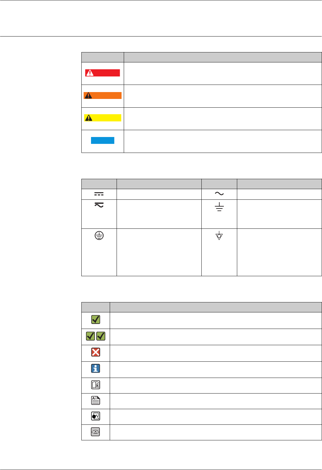
Symbols Safety symbols
Symbol Meaning
DANGER
DANGER!
This symbol alerts you to a dangerous situation. Failure to avoid this situation will result in
serious or fatal injury.
WARNING
WARNING!
This symbol alerts you to a dangerous situation. Failure to avoid this situation can result in
serious or fatal injury.
CAUTION
CAUTION!
This symbol alerts you to a dangerous situation. Failure to avoid this situation can result in
minor or medium injury.
NOTICE
NOTE!
This symbol contains information on procedures and other facts which do not result in
personal injury.
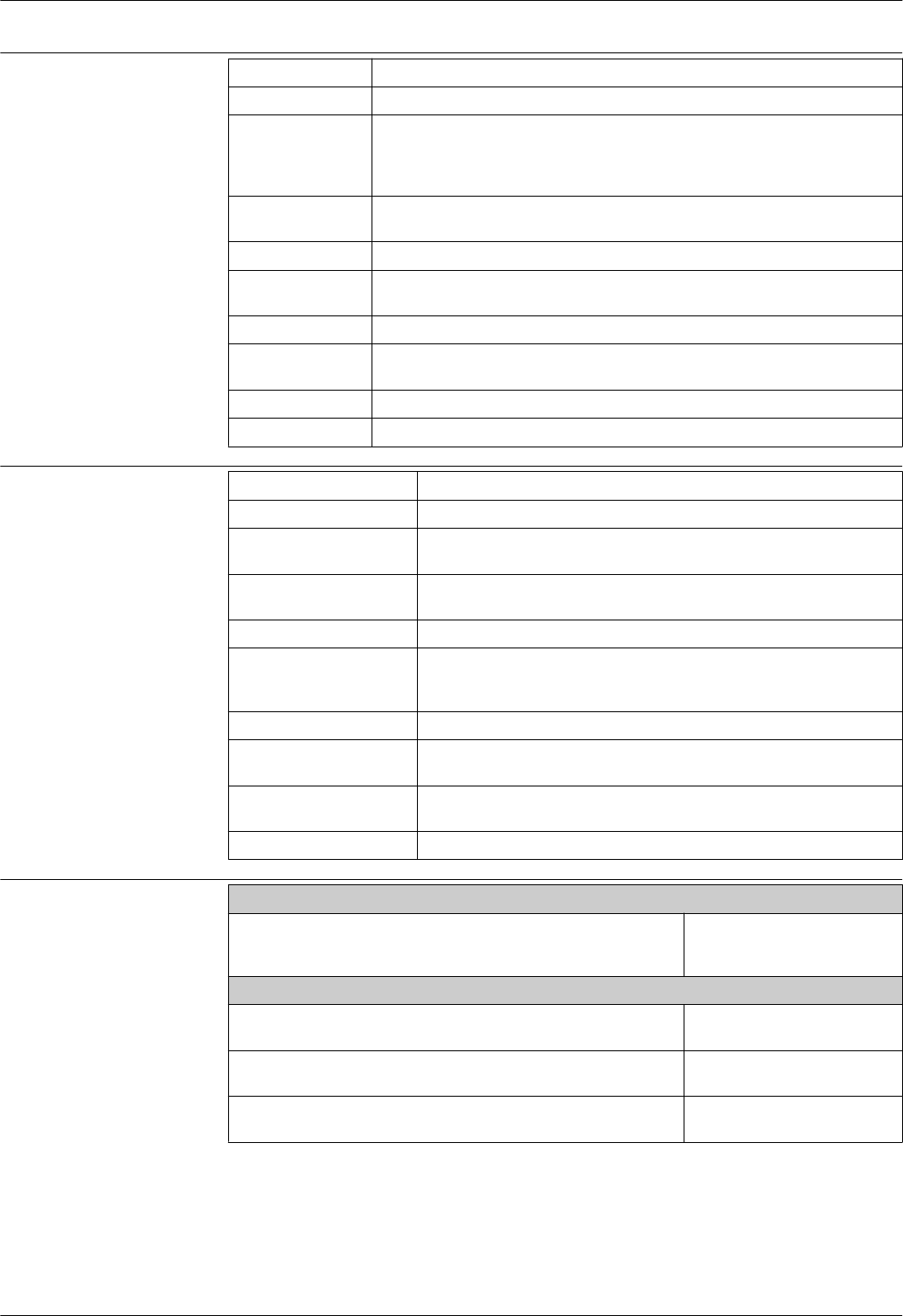
Electrical symbols
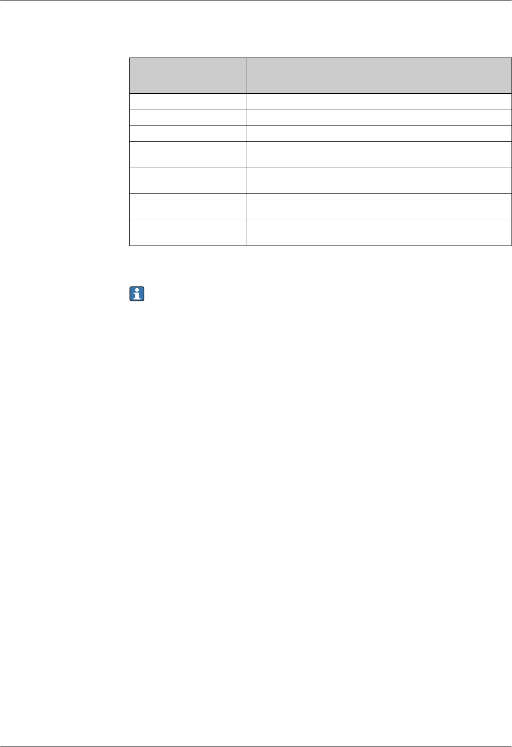
Symbol Meaning Symbol Meaning
Direct current Alternating current
Direct current and alternating current Ground connection
A grounded terminal which, as far as
the operator is concerned, is
grounded via a grounding system.
Protective ground connection
A terminal which must be connected
to ground prior to establishing any
other connections.
Equipotential connection
A connection that has to be connected
to the plant grounding system: This
may be a potential equalization line
or a star grounding system depending
on national or company codes of
practice.
Symbols for certain types of information
Symbol Meaning
Permitted
Procedures, processes or actions that are permitted.
Preferred
Procedures, processes or actions that are preferred.
Forbidden
Procedures, processes or actions that are forbidden.
Tip
Indicates additional information.
Reference to documentation
Reference to page
Reference to graphic
Visual inspection

Micropilot NMR81
4 Endress+Hauser
Symbols in graphics
Symbol Meaning
1, 2, 3 ... Item numbers
,…
,
Series of steps
A, B, C, ... Views
A-A, B-B, C-C, ... Sections
-
Hazardous area
Indicates a hazardous area.
.
Safe area (non-hazardous area)
Indicates the non-hazardous area.
Micropilot NMR81
Endress+Hauser 5
Function and system design
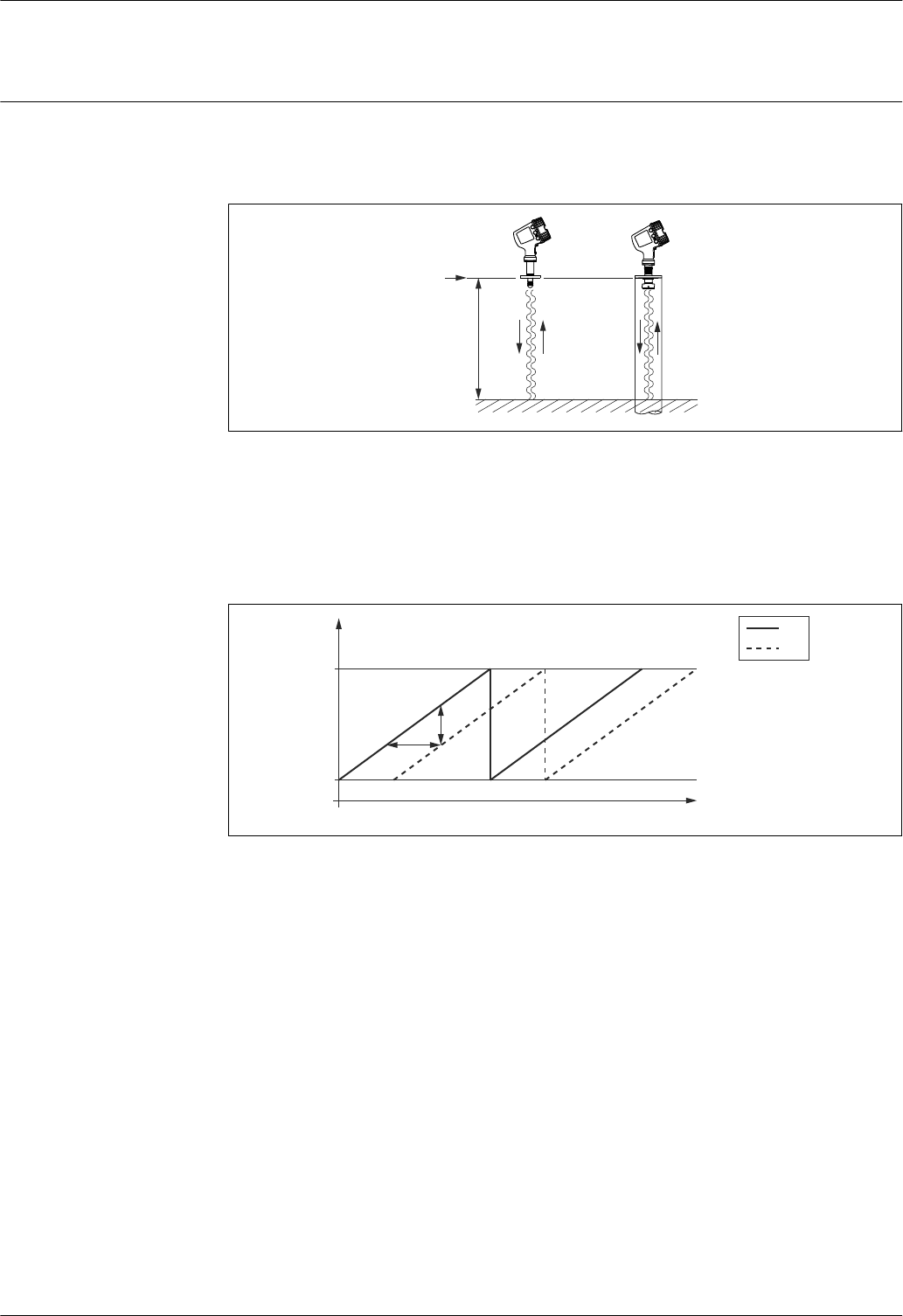
Measuring principle Micropilot is a directional level radar, operating based on the "Frequency-Modulated Continuous
Wave" principle (FMCW). The radar emits a precise crystal-oscillated, continuously varying frequency
wave from the antenna. The wave is reflected off the product surface and received again by the radar
system.
D
R
A0023768
1 FMCW principle: Emission and reflection of the continuous wave.
R Reference point of the measurement
D Distance between R and the product surface
The frequency of this wave is precisely modulated in the form of a sawtooth signal between two limit
frequencies f1 and f2:
f
t
1
2
f2
f1
Δt
Δf
A0023771
2 FMCW principle: Results of the frequency modulation
1 Emitted signal
2 Received signal
Thus, at any given time the frequencies of the emitted and the received signal differ by
Δf = k Δt
where Δt is the transit time and k is the known slope of the frequency modulation.
Δt, on the other hand, is determined by the distance D between the reference point R and the
product surface:
D = (c Δt) / 2
where c is the speed of propagation of the wave.
In summary, D can be calculated from the measured frequency shift Δf. D is then used to calculate
the contents of the tank.
Micropilot NMR81
6 Endress+Hauser
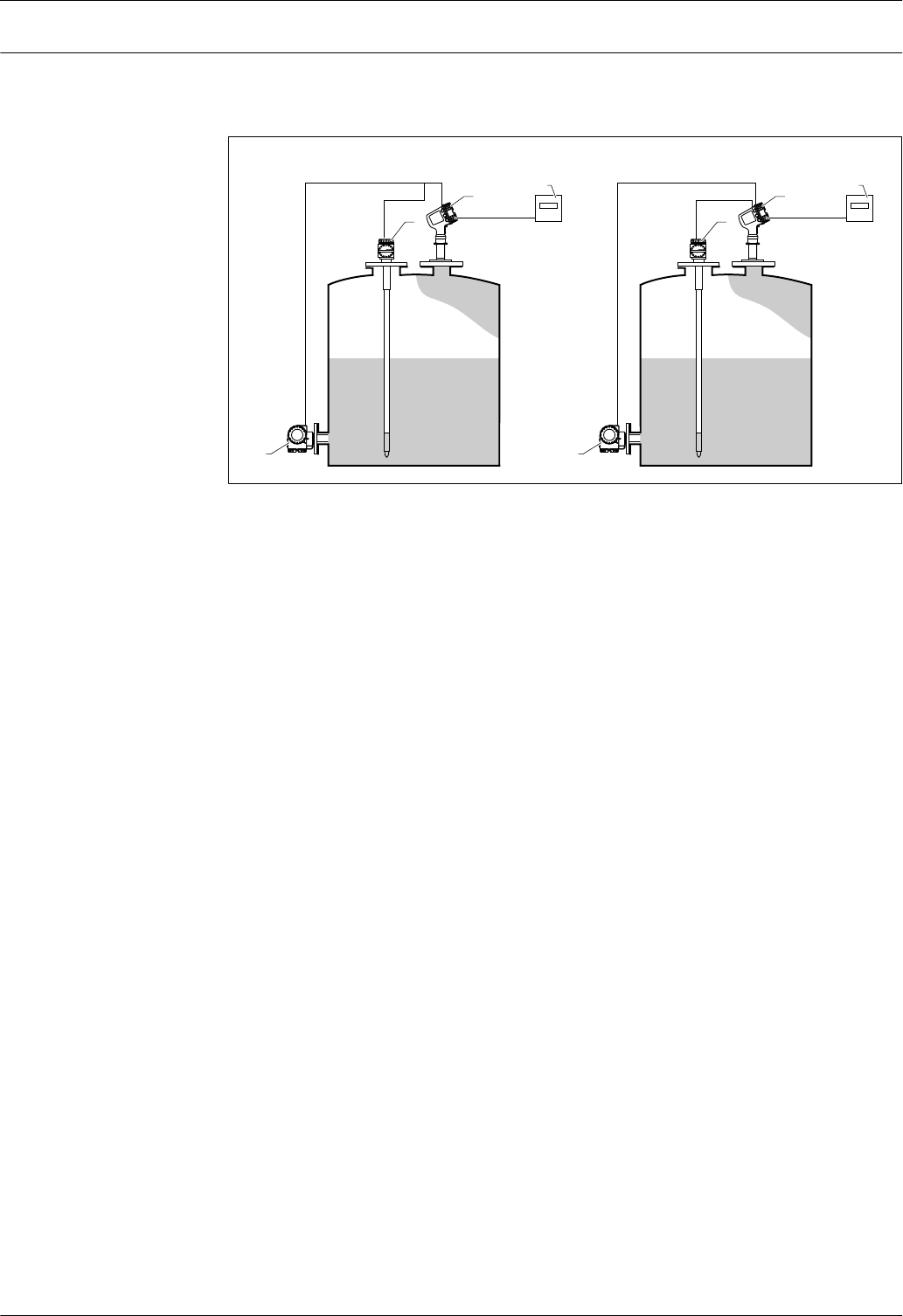
Integration of tank sensors In addition to measuring the level, the device can also be used for the integration of tank sensors
into tank inventory systems. All measured and calculated values can be displayed at the built-in
display. Via a field communication protocol, they can be transferred to an inventory control system.
3 3
4 4
2 2
1 1
HART 4-20 mA
AB
HART HART
5 5
A0023767
3 Integration of tank sensors with Micropilot (Example)
A HART multidrop mode
B HART and analog mode
1 Pressure transmitter
2 Average temperature transmitter
3 Micropilot
4 Field protocol transmits data to an inventory control system
5 Inventory control system (e.g. Tankvision NXA820 or Tankvision Professional NXA85)
Micropilot NMR81
Endress+Hauser 7
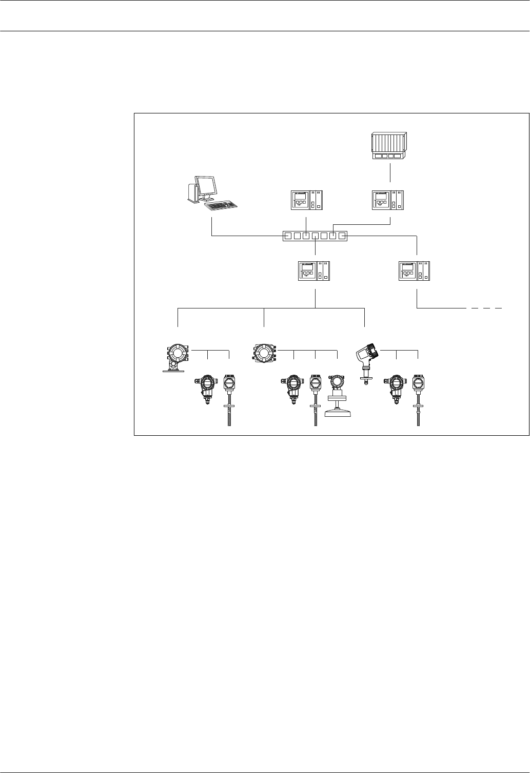
Measuring system •From single tank level measurement to the largest oil refinery applications, Endress+Hauser tank
gauging devices are an integral part of tank farm management solutions. A wide variety of data
output protocols are available for seamless integration into many commonly used systems.
• A primary example is Tankvision from Endress+Hauser. Tankvision is a scalable system offering
local tank management for multiple loops via Modbus or V1 protocols. Accumulated data is
available to DCS and other plant management systems via a Host Link.
NXA820
NXA820
NXA820
NXA820
8
910
12
7
1
223 3 5 2 3
4 6
8
13
11
15
14
A0027700
4 Integration of tank gauging devices into an inventory management system (typical example)
1 Proservo NMS8x
2 Pressure transmitter (e.g. Cerabar)
3 Temperature transmitter (e.g. Prothermo)
4 Tankside Monitor NRF81
5 Micropilot S FMR5xx
6 Micropilot NMR8x
7 Field protocol (e.g. Modbus, V1)
8 Tankvision Tank Scanner NXA820
9 Ethernet
10 Ethernet switch
11 Internet Browser
12 Tankvision Data Concentrator NXA821
13 Tankvision Host Link NXA822
14 Modbus
15 DCS or PLC
Micropilot NMR81
8 Endress+Hauser
Input
Measured variable The measured variable is the distance between a reference point (mounting flange) and a reflective
surface (e.g. product surface).
Maximum measuring range The maximum measuring range depends on the dielectric constant εr of the measured medium and
on the size of the antenna:
Dielectric constant εrAntenna 1)
50mm/2" 80mm/3" 100mm/4"
1.4 to 1.9 0.8 to 4 m (2.6 to 13 ft) 15 m (49 ft) 25 m (82 ft)
1.9 to 4 8 m (26 ft) 30 m (98 ft) 50 m (164 ft) 2)
4 to 10 20 m (66 ft) 60 m (197 ft) 2) 70 m (230 ft) 2)
> 10 30 m (98 ft) 70 m (230 ft) 2) 70 m (230 ft) 2)
1) Feature 100 of the product structure
2) For devices with Weight+Measure approval: Maximum measuring range: 30 m (97 ft)
For dielectric constants (DC values) of many media commonly used in various industries refer
to:
•the Endress+Hauser DC manual (CP01076F)
• the Endress+Hauser "DC Values App" (available for Android and iOS)
For devices with Weight+Measure approval (option LK or LL of ordering feature 590
"Additional Approval"): Maximum measuring range: 0.8 to 30 m (2.6 to 97 ft)
The actual usable measuring range depends on additional criteria like the mounting location or
possible interference reflections.
Operating frequency Device Operating frequency
NMR81 approx. 78 GHz
Transmitting power Device Peak pulse power Average output power
NMR81 6.3 mW 63 µW
HART Ex ia/IS active input
D
E
G
F
C
B
A
1
1
1
1
13
2
3
2
2 4
1
HR
CDI
WP
on
SIM
2
2
3
3
4
4
1
1
2
2
3
3
4
4
5
5
6
6
7
7
8
8
POWER
i
E1
1
2
CDI
D
C
1234
1234
A0027364
5 HART Ex ia/IS active input
E1 HART +
E2 HART -
The device has a HART Ex ia/IS active input. Additional features are provided if the following
Endress+Hauser devices are connected:
Prothermo NMT
The measured level is transmitted to the Prothermo. Prothermo uses this level to calculate the
average temperature of the product.
Micropilot NMR81
Endress+Hauser 9
Output
I/O modules
E
G
F
1
1
1
1 3
2
2
2 4
HR
CDI
WP
on
SIM
POWER
i
D
C
B
A
1
1
2
2
3
3
4
4
1
1
2
2
3
3
4
4
5
5
6
6
7
7
8
8
D
E
F
C
B
A
1
1
1
13
2
2 4
1
HR
CDI
WP
on
SIM
2
2
3
3
4
4
1
1
2
2
3
3
4
4
5
5
6
6
7
7
8
8
i
G1
3
2
POWER
A0027363
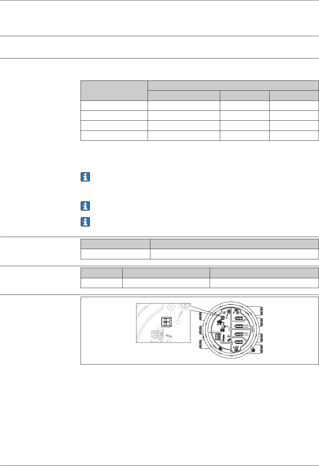
6 Position of the I/O modules in the terminal compartment
The terminal compartment contains up to four I/O modules, depending on the order code.
• Modules with four terminals can be in any of these slots.
• Modules with eight terminals can be in slot B or C.
The exact assignment of the modules to the slots is dependent on the device version. For a
detailed description refer to the Operating Instructions of the device in question.
The following restrictions apply when selecting the modules:
•The device may contain a maximum of four I/O modules.
• A maximum of two I/O modules with 8 terminals is possible.
Ordering feature 040: "Primary Output"
NMx8x - XX xx xxxxxx ...
040
Option Number of I/O modules Type of I/O module Number of terminals Technical data
A1 1 Modbus RS485 4 → 10
B1 1 V1 4 → 11
E1 1 4-20mA HART Ex d/XP 8 → 11
H1 1 4-20mA HART Ex i/IS 8 → 11
Ordering feature 050: "Secondary IO Analogue"
NMx8x - xx XX xxxxxx ...
050
Option Number of I/O
modules
Type of I/O module Number of terminals Technical data
A1 1 1 x "Ex d/XP 4-20mA HART + RTD input" 1 x 8 → 11
A2 2 2 x "Ex d/XP 4-20mA HART + RTD input" 2 x 8 → 11
B1 1 1 x "Ex i/IS 4-20mA HART+ RTD input" 1 x 8 → 11
B2 2 2 x "Ex i/IS 4-20mA HART+ RTD input" 2 x 8 → 11
C2 2 1 x "Ex i/IS 4-20mA HART + RTD input"
1 x "Ex d/XP 4-20mA HART + RTD input"
2 x 8 → 11
X0 0 none 0 -
Micropilot NMR81
10 Endress+Hauser
Ordering feature 060: "Secondary IO Digital Exd"
NMx8x - xx xx XXxxxx ...
060
Option Number of I/O modules Type of I/O module Number of terminals Technical data
A1 1 1 x "2x relay + 2x discrete I/O" 1 x 4 → 11
A2 2 2 x "2x relay + 2x discrete I/O" 2 x 4 → 11
A3 3 3 x "2x relay + 2x discrete I/O" 3 x 4 → 11
B1 1 1x "Modbus RS485" 1 x 4 → 10
B2 2 1x "Modbus RS485"
1 x "2x relay + 2x discrete I/O"
2 x 4 → 10
→ 11
B3 3 1x "Modbus RS485"
2 x "2x relay + 2x discrete I/O"
3 x 4 → 10
→ 11
X0 0 none 0 -
"Modbus RS485": Technical
data No. of units Maximum 15 instruments per loop
Baud rate Selectable:
•600 bit/s
• 1 200 bit/s
• 2 400 bit/s
• 4 800 bit/s
• 9 600 bit/s
• 19 200 bit/s
Parity Selectable:
• Odd
• Even
• None
Cable Three-wire cable with screening. The screening must be connected inside the housing.
Termination resistors To be set as required in specific environments
Topology • Serial bus
•Tree structure
Transmission distance Maximum 1 200 m (3 900 ft) including limbs or branches;
branches under 3 m (9.8 ft) are negligible
Instrument address Each transmitter has an individual bus address configured in the software of the
transmitter.
Isolation Bus inputs are electrically isolated from the other electronics.
Error on alarm Error message classified according to NAMUR NE 107
Micropilot NMR81
Endress+Hauser 11
"V1": Technical data No. of units Maximum 10 instruments per loop
Baud rate 3 300 bit/s
Parity Selectable:
• Odd
• Even
• None
Cable • Two-wire twisted pair; screening recommended
• Two-wire unscreened
Termination resistors Not required
Topology • Serial bus
• Tree structure
Transmission distance Maximum 6 000 m (19 700 ft)
Instrument address Each transmitter has an individual bus address configured in the software of the
transmitter.
Isolation Serial communication circuit isolated from other circuits
Error on alarm Error message classified according to NAMUR NE 107
"4-20mA HART" I/O module
(Ex d/XP or Ex i/IS):
Technical data
No. of units Max. 6 instruments per loop
Baud rate 1 200 bit/s
Cable Two-wire, twisted pair screened cable;
Core cross section: 0.2 to 2.5 mm2 (24 to 13 AWG)
Topology • Serial bus
• Tree structure
Transmission distance Maximum 1 200 m (3 900 ft)
Instrument address Each transmitter on a signal loop has an individual bus address. This is defined
within the transmitter software and / or auxiliary configuration environment
such as host system or Field Communicator 475.
Isolation Bus inputs are electrically isolated from the other electronics
Connection of a Prothermo
NMT
The measured level is transmitted to the Prothermo. Prothermo uses this level
to calculate the average temperature of the product.
Connection of a RTD
temperature probe
3-wire or 4-wire connection
Error on alarm Error message classified according to NAMUR NE 107
"Digital I/O module":
Technical data Output
Relay switching power for resisitive load • 30 VDC @ 2 A
• 250 VDC @ 0.1 A
• 250 VAC @ 2 A
Input
Maximum pick-up voltage • 250 VAC
•250 VDC
Minimum drop-out voltage • 25 VAC
• 5 VDC
Current consumption at maximum voltage • ≤ 1 mA (DC)
• ≤ 2 mA (AC)
Micropilot NMR81
12 Endress+Hauser
Power supply
Terminal assignment
D
E
F
C
B
A
1
1
1
13
2
2 4
1
HR
CDI
WP
on
SIM
2
2
3
3
4
4
1
1
2
2
3
3
4
4
5
5
6
6
7
7
8
8
i
D
E
F
C
B
A
1
1
1
1 3
2
2 4
1
HR
CDI
WP
on
SIM
2
2
3
3
4
4
1
1
2
2
3
3
4
4
5
5
6
6
7
7
8
8
i
G1
3
2
POWER
G1
3
2
POWER
G1 L
G3 N
AC 85...264 V
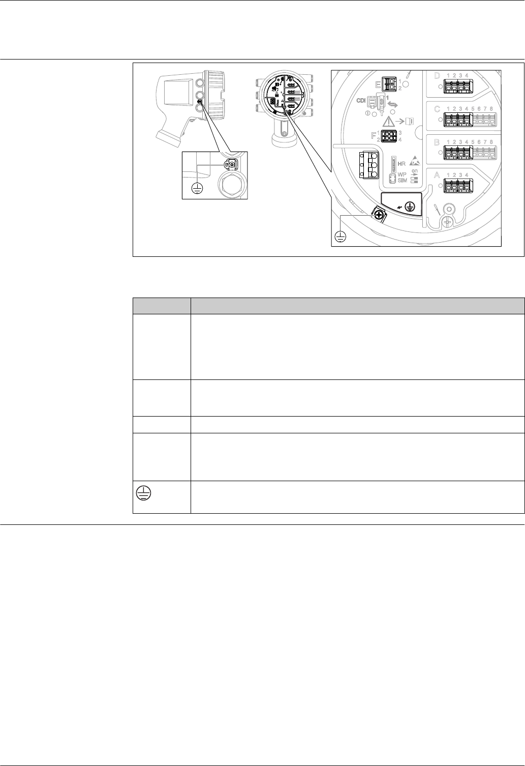
A0026372
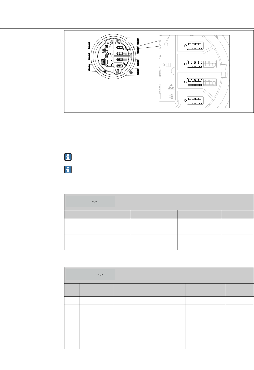
7 Terminal compartment (typical example) and ground terminals
Terminal area Module
A/B/C/D
Up to four I/O modules, depending on the order code → 9
•Modules with four terminals can be in any of these slots.
• Modules with eight terminals can be in slot B or C.
The exact assignment of the modules to the slots is dependent on the device version. For
a detailed description refer to the Operating Instructions of the device in question.
E HART Ex i/IS interface
• E1: H+
• E2: H-
F Remote display (in preparation)
G
Power supply: 85 to 264 VAC
• G1: L
• G2: not connected
• G3: N
A0018339
Protective ground connection
Supply voltage 100 to 240 VAC
Micropilot NMR81
Endress+Hauser 13
Cable entries Ordering feature 090 "Electrical Connection" 1) Cable entries (with blind plugs)
A 7 x thread M20
B 7 x thread M25
C 7 x thread G1/2
D 7 x thread G3/4
E 7 x thread NPT1/2
F 7 x thread NPT3/4
1) Position 13 of the order code, e.g. NMx8x-xxxxxxxxxxxxA...
For the following devices with TIIS Ex d approval, cable glands are attached to the device (see
position 1 and 2 of the order code). These cable glands must be used.
•Micropilot NMR81-TA...
• Micropilot NMR81-TC...
• Micropilot NMR81-TE...
Cable specification Terminals
Terminal Wire cross section
Signal and power supply
•Spring terminals (NMx8x-xx1...)
• Screw terminals (NMx8x-xx2...)
0.2 to 2.5 mm2 (24 to 13 AWG)
Ground terminal in the terminal compartment max. 2.5 mm2 (13 AWG)
Ground terminal at the housing max. 4 mm2 (11 AWG)
Power supply line
Standard device cable is sufficient for the power line.
HART communication line
•Standard device cable is sufficient if only the analog signal is used.
• Shielded cable is recommended if using the HART protocol. Observe the grounding concept of the
plant.
Modbus communication line
• Observe the cable conditions from the TIA-485-A, Telecommunications Industry Association.
• Additional conditions: Use shielded cable.
V1 communication line
• Two wire (twisted pair) screened or un-screened cable
• Resistance in one cable: ≤ 120 Ω
• Capacitance between lines: ≤ 0.3 µF
Overvoltage protection On the communication and power lines; according to IEC 60060-1 /DIN 60079-14:
10 kA, 8/20 μs, 10 pulses according to IEC 60060-1 / DIN 60079-14
Micropilot NMR81
14 Endress+Hauser
Performance characteristics
Reference operating
conditions
According to OIML R85 (2008)
•Temperature: –25 to +55 °C (–13 to 131 °F)
• Atmospheric pressure
• Relative humidity (air): 65 % ±15 %
• Medium with good reflectivity and calm surface
• Signal beam hits the tank wall only at one side
• No major interference reflections inside the signal beam
Measured value resolution ≤ 0.1 mm (0.004 in)
Maximum measured error The following values are valid for a measuring distance up to 30 m (100 ft)
Ordering feature 150 "Accuracy, Weight + Measure Approval" 1) Maximum measured error
• NTA: Maximum Performance, NMi type approval (in preparation)
•PTA: Maximum Performance, PTB type approval (in preparation)
±0.5 mm (±¹⁄₃₂ in)
• NTC: Custody transfer type approval according to NMi (in preparation)
• PTC: Custody transfer type approval according to PTB (in preparation)
±1 mm (±¹⁄₁₆ in)
• ICR: Standard version, w/o calibration certificate
• ICW: Standard version, 3-point calibration certificate
• ICX: Standard version, 5-point calibration certificate
±1 mm (±¹⁄₁₆ in)
1) Position 21 to 23 in the order code (e.g. NMR8x-xxxxxxxxxxxxxxxxxxxxICR...)
Hysteresis 0.2 mm (0.008 in)
Repeatability 0.2 mm (0.008 in)
Linearity Within maximum measured error
Long-term drift Within the specified error of measurement
Influence of ambient
temperature
Within the specified accuracy according to OIML R85 (2008)
Micropilot NMR81
Endress+Hauser 15
Installation
Installation conditions Mounting position
General conditions
• Do not install in the centre of the tank.
• Do not install above a filling stream.
• Avoid any tank installations (e.g. limit switches, temperature probes) within in the signal beam.
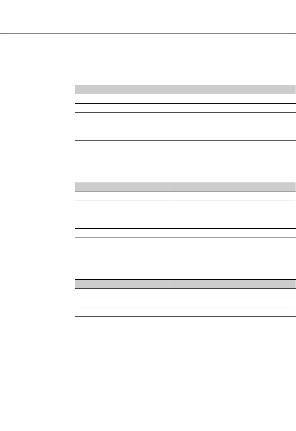
Minimum wall distance for the 50mm/2" antenna 1)
Measuring range Minimum wall distance
5 m (16 ft) 0.3 m (0.98 ft)
10 m (33 ft) 0.6 m (1.9 ft)
15 m (49 ft) 0.9 m (2.9 ft)
20 m (66 ft) 1.2 m (3.9 ft)
25 m (82 ft) 1.5 m (4.9 ft)
30 m (98 ft) 1.8 m (5.9 ft)
1) Ordering feature 100 "Antenna", option AB
Minimum wall distance for the 80mm/3" antenna 1)
Measuring range Minimum wall distance
5 m (16 ft) 0.17 m (0.55 ft)
10 m (33 ft) 0.33 m (1.1 ft)
15 m (49 ft) 0.5 m (1.6 ft)
20 m (66 ft) 0.67 m (2.2 ft)
25 m (82 ft) 0.83 m (2.7 ft)
30 m (98 ft) 1.0 m (3.3 ft)
1) Ordering feature 100 "Antenna", option AC
Minimum wall distance for the 100mm/4" antenna 1)
Measuring range Minimum wall distance
5 m (16 ft) 0.13 m (0.44 ft)
10 m (33 ft) 0.27 m (0.87 ft)
15 m (49 ft) 0.4 m (1.3 ft)
20 m (66 ft) 0.53 m (1.7 ft)
25 m (82 ft) 0.67 m (2.2 ft)
30 m (98 ft) 0.8 m (2.6 ft)
1) Ordering feature 100 "Antenna", option AD

Micropilot NMR81
Endress+Hauser 17
Vertical alignment of the 50mm(2") and 80mm (3") antenna
For optimum measuring accuracy the antenna must be installed at right angles to the medium
surface. An adjustable seal is available for the alignment → 38.
Vertical alignment of the 100mm(4") antenna
For optimum measuring accuracy the antenna must be installed at right angles to the medium
surface. For this purpose the 100mm(4") antenna always has an alignment unit. A level tool
indicating the correct alignment is attached to the alignment tool.
±25°
90 °
A
1
A0027776
8 Alignment unit of the 100mm(4") antenna
1 Level tool indicating the correct alignment
Micropilot NMR81
18 Endress+Hauser
Environment
Ambient temperature range Device –40 to +60 °C (–40 to +140 °F)
Display
module
–20 to +70 °C (–4 to +158 °F)
The readability of the display may be impaired at temperatures outside this temperature
range.
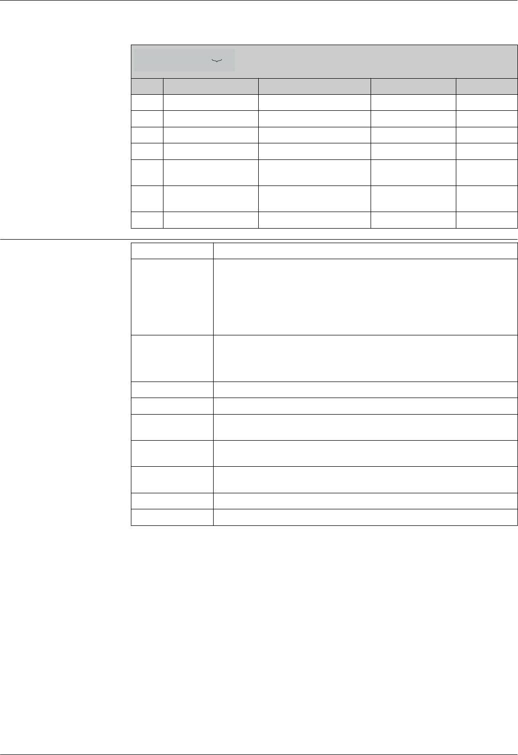
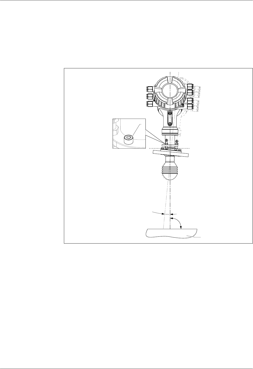
Ambient temperature limits The following diagrams take into account only functional aspects. There may be further
restrictions for certified device versions. Please refer to the separate Safety Instructions.
Device configuration
The ambient temperature limits depend on the I/O modules present in the slots of the terminal
compartment. Data are given for the following five typical configurations:
I/O configuration
D
C
B
A
1
1
2
2
3
3
4
4
1
1
2
2
3
3
4
4
5
5
6
6
7
7
8
8
A0023888
1 (worst case)
2 (best case) - - - -
3 - -
4 - - -
5 -
Micropilot NMR81
Endress+Hauser 19
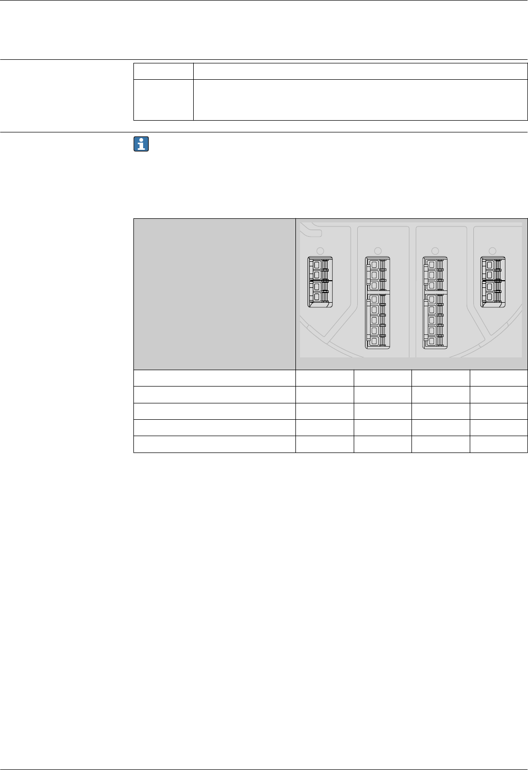
With a temperature (Tp) at the process connection the admissible ambient temperature (Ta) is
reduced according to the following diagram (temperature derating):
Ambient temperature limits for NMR81
Temperature unit: °C (°F)
Tp
P5 P4
P3
P2
P1 Ta
A0019351
I/O configuration P1 P2 P3 P4 P5
TpTaTpTaTpTaTpTaTpTa
1 -40
(-40)
55
(131)
55
(131)
55
(131)
200
(392)
48
(119)
200
(392)
-40
(-40)
-40
(-40)
-40
(-40)
2 -40
(-40)
60
(140)
60
(140)
60
(140)
200
(392)
55
(131)
200
(392)
-40
(-40)
-40
(-40)
-40
(-40)
3 -40
(-40)
55
(131)
55
(131)
55
(131)
200
(392)
51
(124)
200
(392)
-40
(-40)
-40
(-40)
-40
(-40)
4 -40
(-40)
60
(140)
60
(140)
60
(140)
200
(392)
53
(128)
200
(392)
-40
(-40)
-40
(-40)
-40
(-40)
5 -40
(-40)
55
(131)
55
(131)
55
(131)
200
(392)
50
(122)
200
(392)
-40
(-40)
-40
(-40)
-40
(-40)
Classification of
environmental conditions
according to DIN EN
60721-3-4
4K5, 4K6, 4B1, 4M7, 4Z2, 4Z3, 4Z8
Storage temperature –50 to +80 °C (–58 to +176 °F)
Humidity ≤ 95 %
Degree of protection •IP68/66 according to DIN EN 60529
• Type 6P/4x according to NEMA 250
Shock resistance •30 g (18 ms) according to DIN EN 60068-2-27 (1993)
• Classification according to DIN EN 60721-3-4: 4M7
Vibration resistance •20 to 2 000 Hz, 1 (m/s2)2/Hz according to DIN EN 60068-2-64 (1994)
• This corresponds to an acceleration value of 4.5 g and fulfills class 4M7 of DIN EN 60721-3-4
(1995)
Electromagnetic
compatibility (EMC)
•Transient emissions according to DIN EN 61326, class B
• Interference resistance according to DIN EN 61326, Appendix A (Industry use) and NAMUR
recommendation NE21

Micropilot NMR81
20 Endress+Hauser
Process
Process temperature range Device Process temperature range
NMR81 –40 to +200 °C (–40 to 392 °F)
Process pressure range Device Process pressure range
NMR81 –1 to +16 bar (–14.5 to +232 psi)
Dielectric constant Application Dielectric constant
Free space εr ≥ 1.9
Micropilot NMR81
Endress+Hauser 21
Custody transfer approval
Ordering feature 150
"Accuracy, Weight + Measure
Approval" 1)
Accuracy properties
ICR Standard version (±1 mm), without calibration certificate
ICW Standard version (±1 mm), 3-point calibration certificate
ICX Standard version (±1 mm), 5-point calibration certificate
NTA (in preparation) Maximum performance (±0.5 mm), type approval according to NMi, OIML
R85, API 3.1B, ISO4622, factory calibration certificate
NTC (in preparation) Custody transfer (±1 mm) type approval according to NMi, OIML R85, API
3.1B, ISO4622, factory calibration certificate
PTA (in preparation) Maximum performance (±0.5 mm), PTB type approval, factory calibration
certificate
PTC (in preparation) Custody transfer (±1 mm) type approval per PTB, factory calibration
certificate
1) Position 21 to 23 in the order code (e.g. NMR8x-xxxxxxxxxxxxxxxxxxxxICR...)
Micropilot NMR8x that are certified for Custody Transfer applications are calibrated on a
certified production rig. The production rig reference standard is a laser tracker with an
absolute accuracy of ±0.016 mm and a resolution of 0.0001 mm. Calibration is performed at 10
equally-spaced measuring points over the full measuring range.
The Maximum Permissible Error (MPE) is ±0.5 mm (±¹⁄₃₂ in) for Maximum performance
models, and ±1 mm (±¹⁄₁₆ in) for Custody transfer models. The resultant Factory Calibration
Certificate is included in the scope of delivery along with the respective type approval
certificate.
Micropilot NMR81
22 Endress+Hauser
Mechanical construction
Dimensions Housing
144 (5.67)
215 (8.46)
ø201 (7.91)
A0023482
9 Dimensions of the electronics housing; unit of measurement: mm (in); adapters for cable entries are not
taken into account in this drawing.
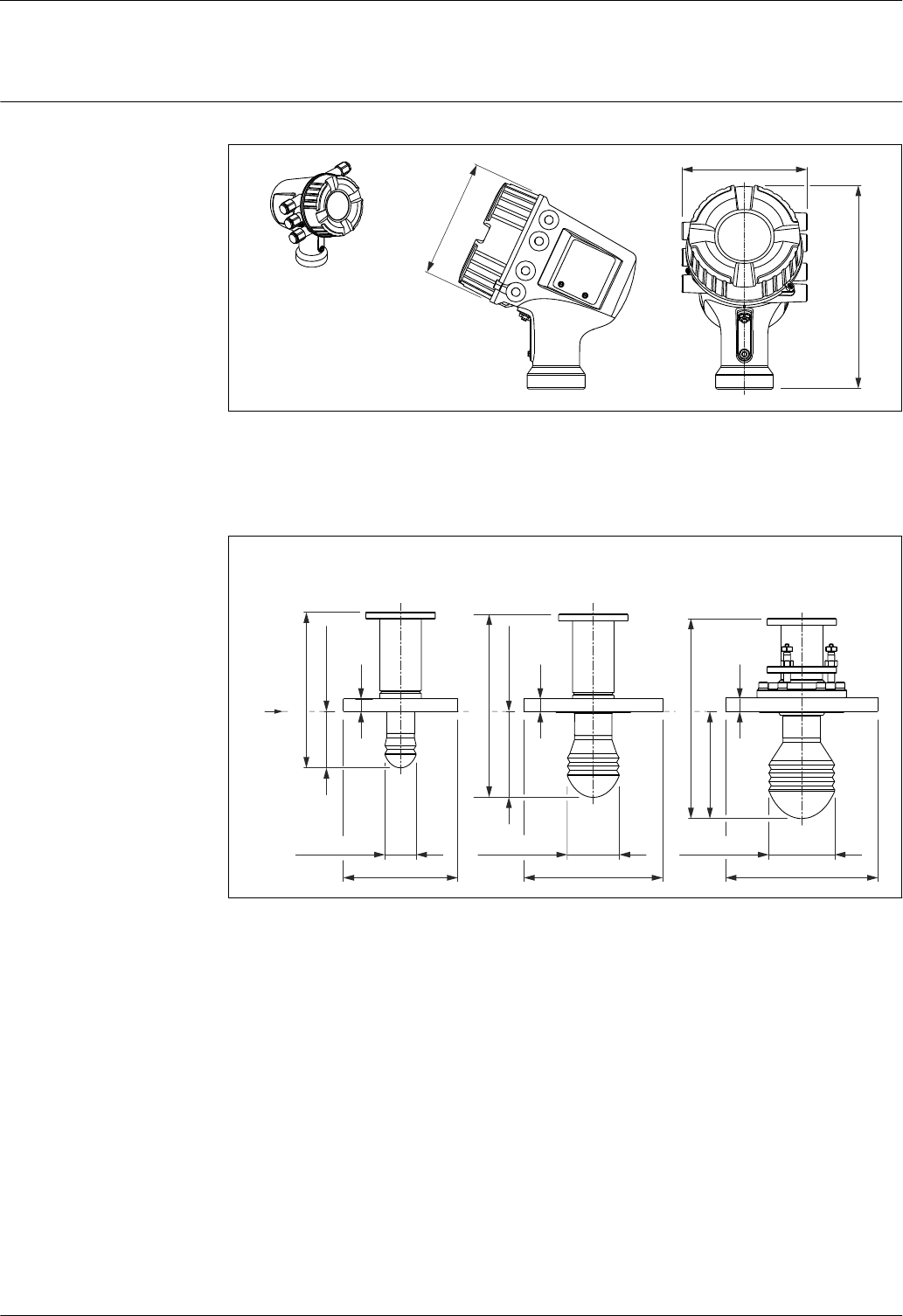
Process connection and sensor
C
øE
ø95 (3.74)
288.5 (11.4)
154.5 (6.08)
B
øE
ø75 (2.95)
264.5 (10.5)
124 (4.88)
A
224.5 (8.84)
øE
ø45 (1.77)
81.5 (3.21)
b
b
b
R
A0023871
10 Antenna size; unit of measurement: mm (in)
A Antenna: 50mm/2"
B Antenna: 80mm/3"
C Antenna: 100mm/4"
R Reference point of the measurement
Micropilot NMR81
Endress+Hauser 23
Flanges according to ASME B16.5
Pressure
rating 1) Dimension Nominal diameter 1)
2" 3" 4" 6" 8" 10"
150 lbs
b 19.1 mm
(0.75 in)
23.9 mm
(0.94 in)
23.9 mm
(0.94 in)
25.4 mm
(1 in)
28.4 mm
(1.12 in)
30.2 mm
(1.19 in)
E 152.4 mm
(6 in)
190.5 mm
(7.5 in)
228.6 mm
(9 in)
279.4 mm
(11 in)
342.9 mm
(13.5 in)
406.4 mm
(16 in)
300 lbs
b 22.4 mm
(0.88 in)
28.4 mm
(1.12 in)
31.8 mm
(1.25 in)
36.6 mm
(1.44 in)
- -
E 165.1 mm
(6.5 in)
209.5 mm
(8.25 in)
254 mm
(10 in)
317.5 mm
(12.5 in)
- -
1) Ordering feature 140 (position 18 to 20 of the order code)
Flanges according to EN1092-1 (suitable for DIN2527)
Pressure
rating 1) Dimension Nominal diameter 1)
DN50 DN80 DN100 DN150 DN200 DN250
• PN10
• PN16
b 18 mm
(0.71 in)
20 mm
(0.79 in)
20 mm
(0.79 in)
22 mm
(0.87 in)
24 mm
(0.94 in)
26 mm
(1.02 in)
E 165 mm
(6.5 in)
200 mm
(7.87 in)
220 mm
(8.66 in)
285 mm
(11.2 in)
340 mm
(13.4 in)
405 mm
(15.9 in)
• PN25
• PN40
b 20 mm
(0.79 in)
24 mm
(0.94 in)
24 mm
(0.94 in)
28 mm
(1.1 in)
- -
E 165 mm
(6.5 in)
200 mm
(7.87 in)
235 mm
(9.25 in)
300 mm
(11.8 in)
- -
1) Ordering feature 140 (position 18 to 20 of the order code)
Flanges according to JIS B2220
Pressure
rating 1) Dimension Nominal diameter 1)
50A 80A 100A 150A 200A 250A
10 K
b 16 mm
(0.63 in)
18 mm
(0.71 in)
18 mm
(0.71 in)
22 mm
(0.87 in)
22 mm
(0.87 in)
24 mm
(0.94 in)
E 155 mm
(6.1 in)
185 mm
(7.28 in)
210 mm
(8.27 in)
280 mm
(11 in)
330 mm
(13 in)
400 mm
(15.7 in)
1) Ordering feature 140 (position 18 to 20 of the order code)
Flanges according to JPI 7S-15
Pressure
rating 1) Dimension Nominal diameter 1)
80A 100A 150A
150 lbs b 23.9 mm (0.94 in) 23.9 mm (0.94 in) 25.4 mm (1 in)
E 190.5 mm (7.5 in) 228.6 mm (9 in) 279.4 mm (11 in)
300 lbs b 28.4 mm (1.12 in) 31.8 mm (1.25 in) 25.4 mm (1 in)
E 209.5 mm (8.25 in) 254 mm (10 in) 279.4 mm (11 in)
1) Ordering feature 140 (position 18 to 20 of the order code)
Micropilot NMR81
24 Endress+Hauser
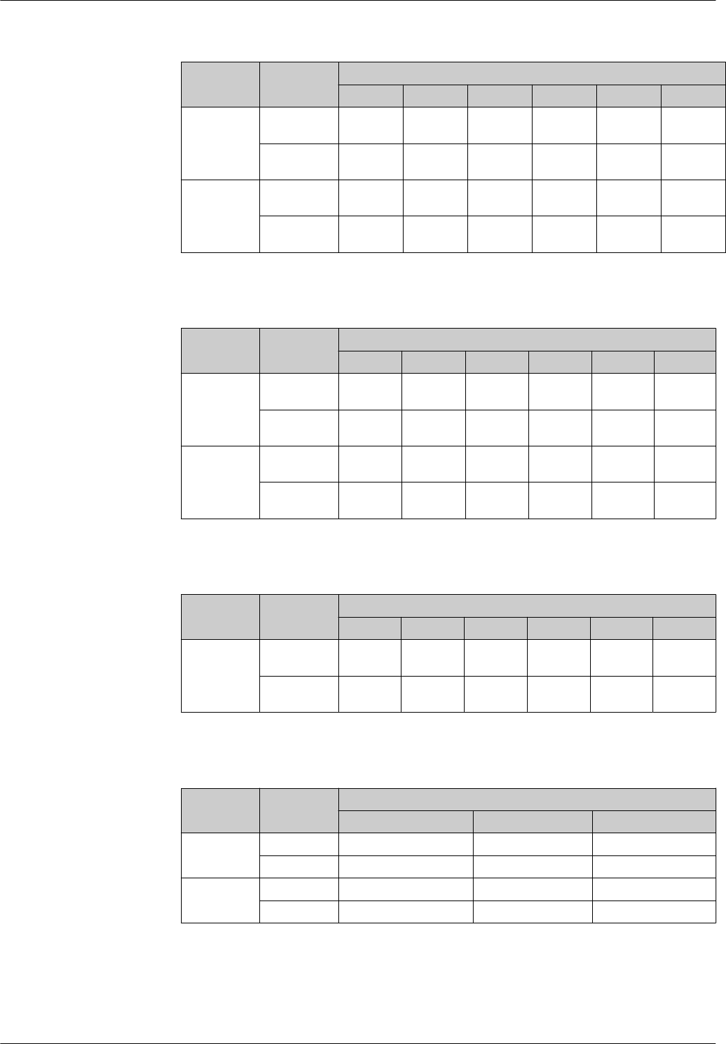
UNI flanges
øK
øD
ø23 (0.91)
ø12 (0.47)
øK
60°
90°
15°
øD
ø26 (1.02)
øK
øD
ø29 (1.14)
60°
AA
A-A
8 (0.31)
3
1
2
M80x1.5
B
D
C
A0027691
11 UNI flanges
B UNI flange DN150/6"/150
C UNI flange DN200/8"/200
D UNI flange DN250/10"/250
Position Option of ordering
feature 140
("Process
Connection") 1)
Suitable for ⌀D ⌀K Material
B RKJ • DN150, PN10/16 (EN1092-1)
•NPS 6" Cl. 150 (ASME B16.5)
• 10K 150A (JIS B2220)
280 mm
(11.0 in)
240 mm
(9.45 in)
1.4301
C RLJ • DN200, PN10/16 (EN1092-1)
• NPS 8" Cl. 150 (ASME B16.5)
• 10K 200A (JIS B2220)
340 mm
(13.4 in)
294.5 mm
(11.6 in)
D RMJ • DN250, PN10/16 (EN1092-1)
• NPS 10" Cl. 150 (ASME B16.5)
• 10K 250A (JIS B2220)
405 mm
(15.9 in)
358 mm
(14.1 in)
1) Position 18 to 20 of the order code)
Weight •Housing with electronics: approx. 12 kg (26 lb)
• Sensor and process connection: 6 to 36 kg (13 to 80 lb); dependent on the device version
Micropilot NMR81
Endress+Hauser 25
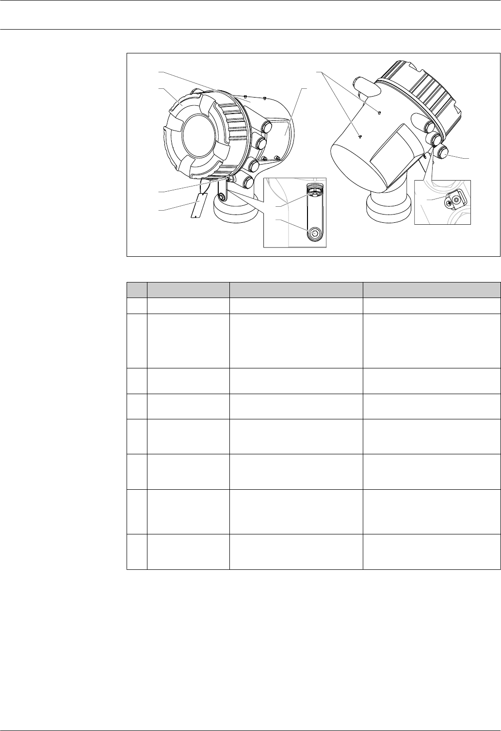
Materials Materials of housing
1
7
8
9
2
4
3
6
5
10
A0027788
Pos. Part Materials for Aluminum version 1) Materials for stainless steel version 2)
1 Housing AC 43000 T6 316L (1.4404)
2 Cover • Cover: AC 43000 T6
• Window: Glass
• Seal: FVMQ
• Thread-coating: Graphite-based
lubricant varnish
• Cover: 316L (1.4404)
• Window: Glass
• Seal: FVMQ
• Thread-coating: Graphite-based
lubricant varnish
3 Cover lock • Capstan screw: 316L (1.4404)
•Clamp: 316L (1.4435)
• Capstan screw: 316L (1.4404)
• Clamp: 316L (1.4435)
4 Tag for measuring
point label
316L (1.4404) 316L (1.4404)
5 Pressure release
stopper for Ex i/IS
chamber
316L (1.4404) 316L (1.4404)
6 Pressure release
stopper for Ex d/XP
chamber
• Stopper: 316L (1.4404)
•O-ring: EPDM
• Stopper: 316L (1.4404)
• O-Ring: EPDM
7 Nameplate • Sticker: Plastic
• Sealing screw: A4
• O-ring: FKM
• Nameplate: 316L (1.4404)
• Groove pins: 316Ti (1.4571)
• Sealing screw: A4
• O-ring: FKM
8 Dummy screws for
weather protection
cover
• Screw: A4-70
•O-ring: EPDM
• Screw: A4-70
• O-ring: EPDM
Micropilot NMR81
26 Endress+Hauser
Pos. Part Materials for Aluminum version 1) Materials for stainless steel version 2)
9 Dummy plug, cable
gland or adapter 3) • Dummy plug
– 1.4435
– LD-PE
• Adapter:
– Ms/Ni (TIIS)
– 1.4404 (other versions)
• Seal:
– EPDM
– NBR
– PTFE tape
• Dummy plug
– 1.4435
– LD-PE
• Adapter:
– Ms/Ni (TIIS)
– 1.4404 (other versions)
• Seal:
– EPDM
– NBR
– PTFE tape
10 Ground terminal • Screw: A4-70
• Spring washer: A4
• Clamp and holder: 316L (1.4404)
• Screw: A4-70
• Spring washer: A4
• Clamp and holder: 316L (1.4404)
1) Ordering feature 070 "Housing", Option "AA"; position 11/12 of the order code: NXXXX-xxxxxxxxxxAA...
2) Ordering feature 070 "Housing", Option "BA"; position 11/12 of the order code: NXXXX-xxxxxxxxxxBA...
3) Depending on device version
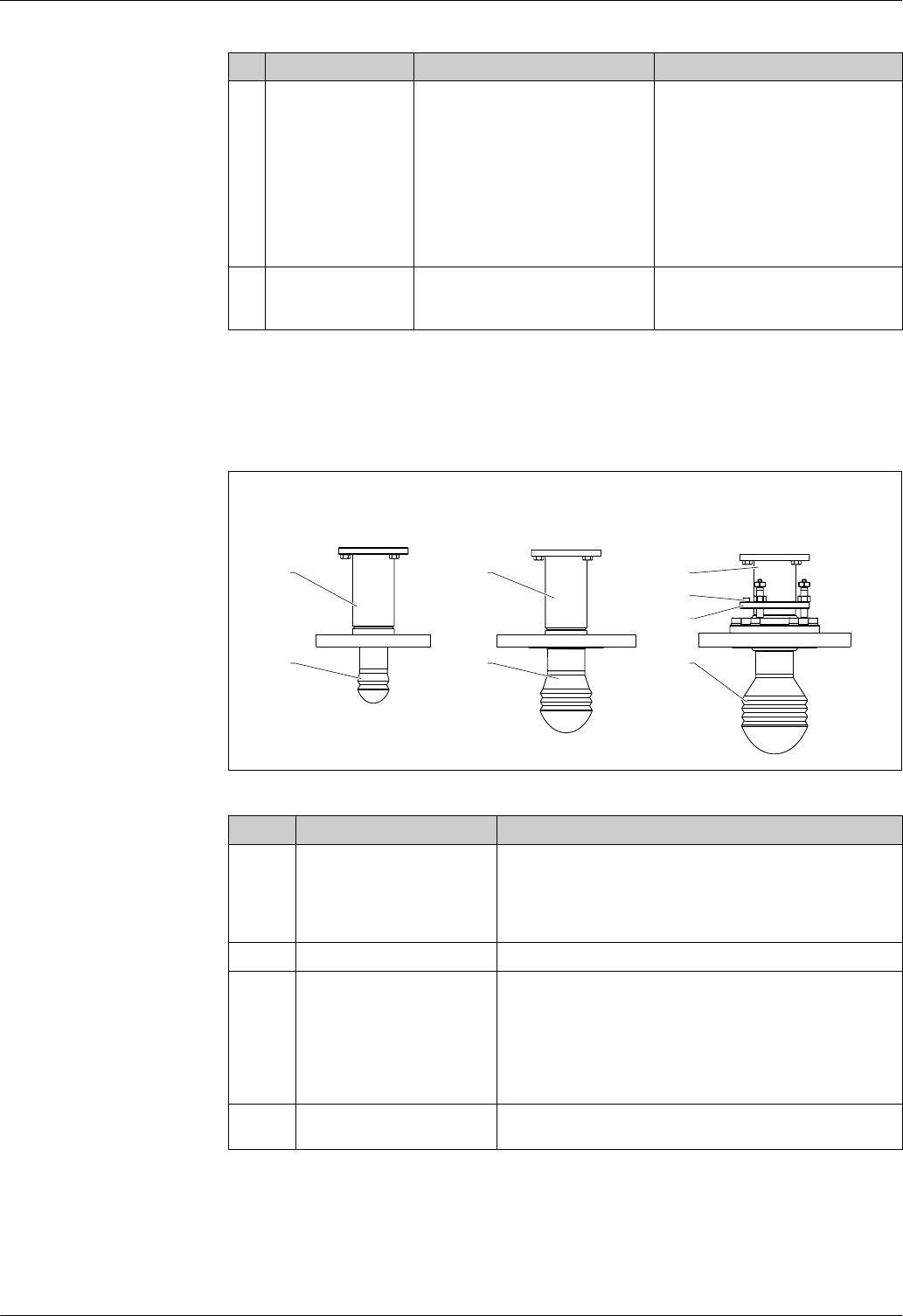
Materials for antenna and process connection
CBA
1 1 1
4 4 4
2
3
A0026322
Pos. Part Material
1 Shaft and flange • Shaft and flange: 316L (1.4404)
•Screws to housing: A2
• Spring washer: 316L (1.4404)
• Insulating sleeve: PPS-GF40
• Set screw: A4
2 Level tool 303 (1.4305)
3 Alignment unit • Locking unit: 316L (1.4404)
• Seal: FKM/FFKM/HNBR
• Locking screws: A4
• Adjusting bolts: 316 (1.4401)
• Nuts for adjusting bolts: A4
• Capstan head screw: A2;
secured by thread-locking fluid
4 Lens antenna • Lens: PTFE
• Seal: FKM/FFKM/HNBR
Micropilot NMR81
Endress+Hauser 27
Operability
Operating concept Operator-oriented menu structure for user-specific tasks
•Commissioning
• Operation
• Diagnostics
• Expert level
Operating languages
• English
• German
• Japanese
Feature 500 of the product structure determines which of these languages is preset on delivery.
Quick and safe commissioning
•Guided menus ("Make-it-run" wizards) for applications
• Menu guidance with brief explanations of the individual parameter functions
Reliable operation
Standardized operation at the device and in the operating tools
Efficient diagnostics increase measurement reliability
• Remedy information is integrated in plain text
• Diverse simulation options
Operating options •Local display; operation via the local display is possible without opening the device.
• Tank Gauging system
• Plant Asset Management tool (e.g. FieldCare); connected via
– HART
– Service port (CDI)
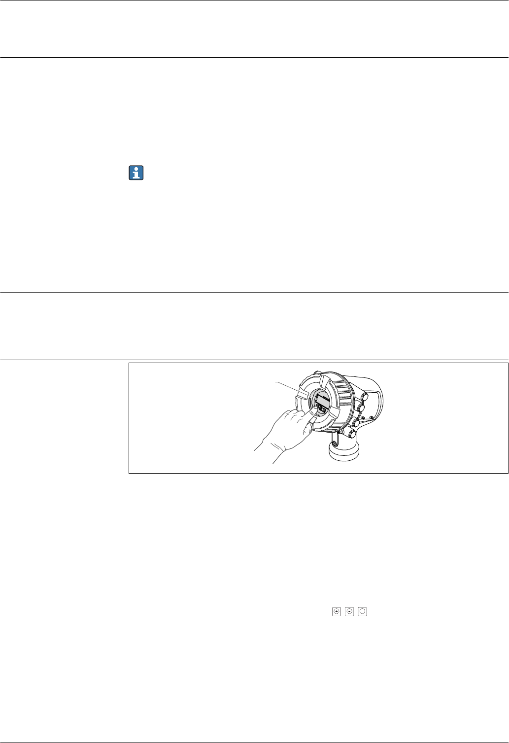
Local operation
1
A0023753
12 Local operation of the Micropilot NMR81/NMR84
1 Display and operating module
Display elements
•4-line display
• White background lighting; switches to red in event of device errors
• Format for displaying measured variables and status variables can be individually configured
• Permitted ambient temperature for the display: –20 to +70 °C (–4 to +158 °F)
The readability of the display may be impaired at temperatures outside the temperature range.
Operating elements
• External operation via touch control; 3 optical keys: , ,
E
• Operating elements also accessible in various hazardous areas
Micropilot NMR81
28 Endress+Hauser
Remote operation
NXA820
5
6
4
1 2 3
7
A0025621
13 Remote operation of Tank Gauging devices
1 Proservo NMS8x
2 Tankside Monitor NRF81
3 Micropilot NMR8x
4 Field protocol (e.g. Modbus, V1)
5 Tankvision Tank Scanner NXA820
6 Ethernet
7 Computer with operating tool (e.g. FieldCare)
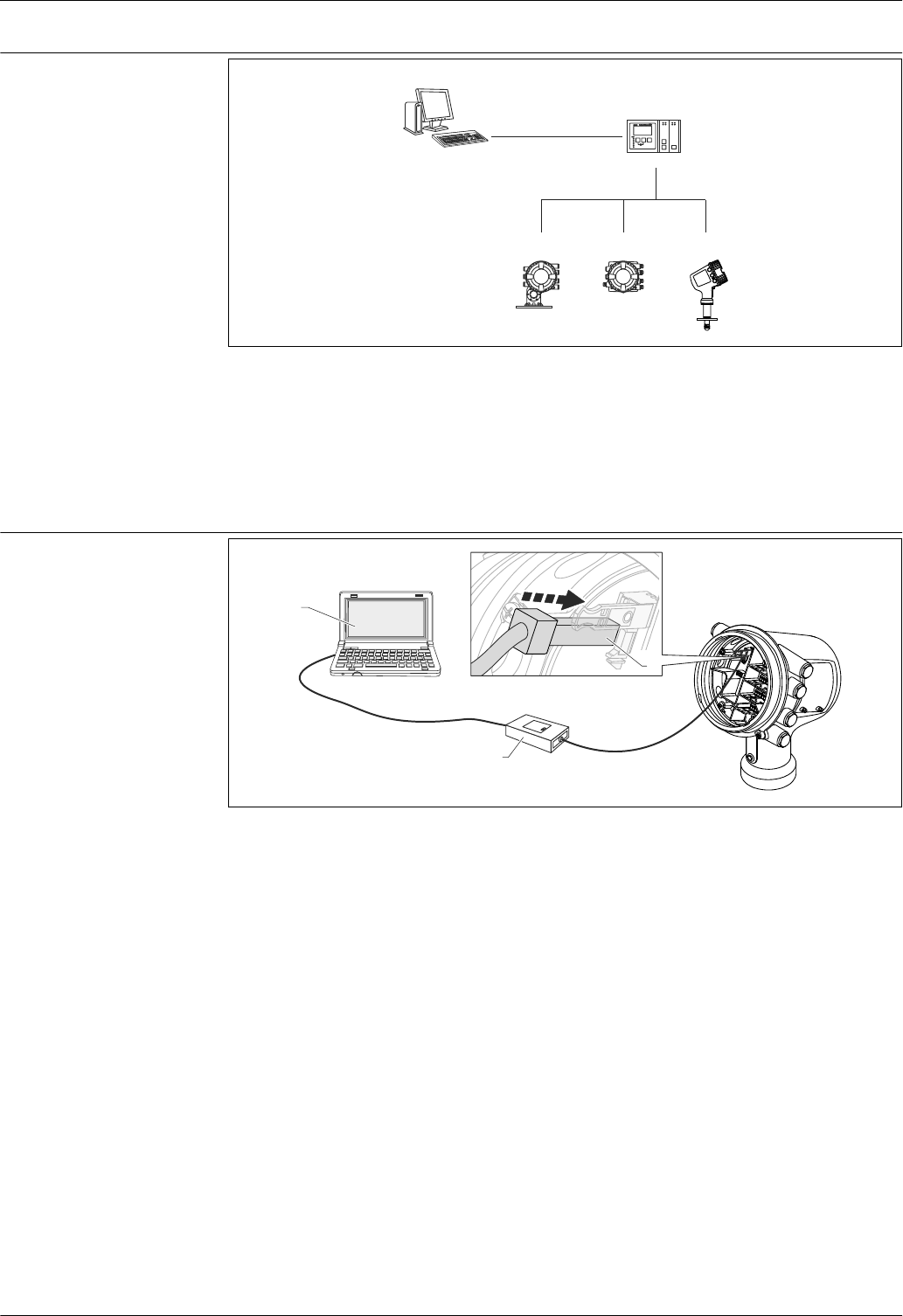
Operation via service
interface
2
3
1
A0023737
14 Operation via service interface
1 Service interface (CDI = Endress+Hauser Common Data Interface)
2 Commubox FXA291
3 Computer with "FieldCare" operating tool and "CDI Communication FXA291" COM DTM
Micropilot NMR81
Endress+Hauser 29
Certificates and approvals
CE mark The measuring system meets the legal requirements of the applicable EC guidelines. These are listed
in the corresponding EC Declaration of Conformity together with the standards applied.
Endress+Hauser confirms successful testing of the device by affixing to it the CE mark.
RCM-Tick marking The supplied product or measuring system meets the ACMA (Australian Communications and Media
Authority) requirements for network integrity, interoperability, performance characteristics as well
as health and safety regulations. Here, especially the regulatory arrangements for electromagnetic
compatibility are met. The products are labelled with the RCM- Tick marking on the name plate.
A0029561
Ex approval The devices are certified for use in hazardous areas and the relevant safety instructions are provided
in the separate "Safety Instructions" (XA) document. Reference is made to this document on the
nameplate.
The separate documentation "Safety Instructions" (XA) containing all the relevant explosion
protection data is available from your Endress+Hauser Sales Center. Allocation of the XA to the
device version: → 40
Dual seal according to
ANSI/ISA 12.27.01
The devices have been designed according to ANSI/ISA 12.27.01 as dual seal devices, allowing the
user to waive the use and save the cost of installing external secondary process seals in the conduit
as required by the process sealing sections of ANSI/NFPA 70 (NEC) and CSA 22.1 (CEC). These
instruments comply with the North-American installation practice and provide a very safe and cost-
saving installation for pressurized applications with hazardous fluids.
Further information can be found in the Safety Instructions (XA) of the relevant devices.
Functional Safety (SIL) in preparation
WHG in preparation
Weight & Measure approval •OIML R85 (2008) (in preparation)
• NMi (in preparation)
• PTB (in preparation)
• PAC (in preparation)
• LNE (in preparation)
• WELMEC (in preparation)
• GOST (in preparation)
The device has a sealable locking switch according to the Weight & Measure requirements. This
switch locks all software parameters related to the measurement. The switching status is
indicated on the display and via the communication protocol.
Radio standard
EN302372-1/2
The devices are conform with the TLPR (Tanks Level Probing Radar) standard EN302372-1/2 and
can always be used in closed tanks or bins. For installation, points a to f in Annex B of EN302372-1
have to be taken into account.
FCC / Industry Canada This device complies with Part 15 of the FCC rules. Operation is subject to the following two
conditions: (1) This device may not cause harmful interference, and (2) this device must accept any
interference received, including interference that may cause undesired operation.
This device complies with Industry Canada licence-exempt RSS standard(s). Operation is subject to
the following two conditions: (1) This device may not interference, and (2) this device must accept
any interference, including interference that may cause undesired operation of the device.
Le présent appareil est conforme aux CNR d'Industrie Canada applicables aux appareils radio exempts
de licence. L'exploitation est autorisée aux deux conditions suivantes : (1) l'appareil ne doit pas
Micropilot NMR81
30 Endress+Hauser
produire de brouillage, et (2) l'utilisateur de l'appareil doit accepter tout brouillage radioélectrique
subi, même si le brouillage est susceptible d'en compromettre le fonctionnement.
[Any] changes or modifications not expressly approved by the party responsible for compliance could
void the user's authority to operate the equipment.
Non-ionizing radiation
protection
According to guideline 2004/40/EG-ICNIRP Guidelines EN50371
Test, certificate Ordering feature 580
"Test, Certificate"
Designation
JA 3.1 Material certificate, wetted metallic parts, EN10204-3.1 inspection certificate
JB Conformity to NACE MR0175, wetted metallic parts
JE Conformity to NACE MR0103, wetted metallic parts
KD Helium leak test, internal procedure, inspection certificate
KE Pressure test, internal procedure, inspection certificate
KG PMI test (XRF), internal procedure, wetted metallic parts, inspection certificate
KP Liquid penetrant test AD2000-HP5-3(PT), wetted/pressurized metallic parts,
inspection certificate
KQ Liquid penetrant test ISO23277-1 (PT), wetted/pressurized metallic parts, inspection
certificate
KR Liquid penetrant test ASME VIII-1 (PT), wetted/pressurized metallic parts, inspection
certificate
KS Welding documentation, wetted/pressurized seams
Other standards and
guidelines
Industry standards
•Directive 2002/95/EC: "Restriction of Hazardous Substances Directive" (RoHS)
• Directive 2004/22/EC: "Measuring Instruments Directive" (MID)
• Directive 97/23/EC: "Pressure Equipment Directive" (PED)
• IEC61508: "Functional Safety of Electrical/Electronic/Programmable Electronic Safety-related
Systems" (SIL)
• NACE MR 0175, NACE MR 0103: "Sulfide stress cracking resistant metallic materials for oilfield
equipment"
• API Recommended Practice 2350: "Overfill Protection for Storage Tanks in Petroleum Facilities"
• API MPMS: "Manual of Petroleum Measurement Standards"
• EN 1127: "Explosive atmospehres - Explosion prevention and protection"
• IEC 60079: "Equipment protection"
• EN 1092: "Flanges and their joints"
• EN 13463: "Non-electrical equipment for use in potentially explosive atmospheres"
• TIA-485-A: "Electrical Characteristics of Generators and Receivers for Use in Balanced Digital
Multipoint Systems "
• IEC61511: "Functional safety - Safety instrumented systems for the process industry sector"
• IEEE 754: "Standard for Binary Floating-Point Arithmetic for microprocessor systems "
• ISO4266: "Petroleum and liquid petroleum products - measurement of level and temperature in
storage tanks by automatic methods"
• ISO6578: "Refrigerated hydrocarbon liquids - Static measurement - Calculation procedure"
• ISO 11223: "Petroleum and liquid petroleum products - Determination of volume, density and
mass of the contents of verical cylindrical tanks by Hybrid Tank Measurement Systems"
• ISO15169: "Petroleum and liquid petroleum products - Direct static measurement - Measurement
of content of vertical storage tanks by hydrostatic tank gauging"
• JIS K2250: "Petroleum Measurement Tables"
• JIS B 8273: "Bolted flange for pressure vessels"
• G.I.I.G.N.L.: "LNG Custody transfer handbook"
• NAMUR NE043: "Standardization of the Signal Level for the Failure Information of Digital
Transmitters"
• NAMUR NE107: "Self-Monitoring and Diagnosis of Field Devices"
• PTBA-A-4.2: "Volume measuring devices for liquids in a stationary condition - Storage containers
and their measuring devices"ur

Micropilot NMR81
Endress+Hauser 31
Metrological standards
•OIML R85 (2008) "Requirements for ambient temperature low –25 °C (–13 °F) and ambient
temperature high +55 °C (+131 °F)
• "Mess- und Eichverordnung" (Calibration regulations for the Federal Republic of Germany)
• Directive 2004/22/EC of the European Parliament and of the Council of 31 March 2004 on
measuring instruments
Micropilot NMR81
32 Endress+Hauser
Ordering information
Ordering information Detailed ordering information is available from the following sources:
•In the Product Configurator on the Endress+Hauser website: www.endress.com -> Click "Corporate"
-> Select your country -> Click "Products" -> Select the product using the filters and search field ->
Open product page -> The "Configure" button to the right of the product image opens the Product
Configurator.
• From your Endress+Hauser Sales Center: www.addresses.endress.com
Product Configurator - the tool for individual product configuration
•Up-to-the-minute configuration data
• Depending on the device: Direct input of measuring point-specific information such as
measuring range or operating language
• Automatic verification of exclusion criteria
• Automatic creation of the order code and its breakdown in PDF or Excel output format
• Ability to order directly in the Endress+Hauser Online Shop
Calibration certificate Option of ordering
feature 150 "Accuracy,
Weight + Measure
Approval" 1)
Calibration certificate Position of the calibration points 2)
ICW 3-point • 2 m (6.6 ft)
•15 m (49 ft)
• 30 m (98 ft)
ICX 5-point • 2 m (6.6 ft)
• 9 m (30 ft)
• 15 m (49 ft)
• 21 m (69 ft)
• 30 m (98 ft)
• NTA (in preparation)
•NTC (in preparation)
• PTA (in preparation)
• PTC (in preparation)
10-point • 2 m (6.6 ft)
• 6 m (20 ft)
• 9 m (30 ft)
• 12 m (39 ft)
• 15 m (49 ft)
• 18 m (59 ft)
• 21 m (69 ft)
• 24 m (79 ft)
• 27 m (89 ft)
• 30 m (98 ft)
1) Positions 21 to 23 of the order code
2) Distance measured from the lower edge of the mounting flange
The position of the calibration points may vary by ±1 cm (±0.04 in).
The calibration points are checked under reference conditions.
Micropilot NMR81
Endress+Hauser 33
Customized parametrization Option of ordering feature 570 "Service" Meaning
IJ Customized parametrization HART (in preparation)
IX Customized parametrization V1 (in preparation)
IZ Customized parametrization Modbus (in preparation)
If one of these options has been selected, customer specific presets can be selected for the following
parameters:
Parameter Selection list / range of values
Tank reference height 0 to 999 999.9 mm
Marking Option of ordering feature 895
"Marking"
Meaning
Z1 Tagging (TAG)
Z2 Bus address
Optionally, the device can be ordered with a specific tagging and/or bus address according to the
table above. When the respective option is selected, the tag or bus address must be defined in an
additional specification.
Micropilot NMR81
34 Endress+Hauser
Application packages
Advanced tank measurement
methods
The device software provides the following tank measurement methods:
•Direct level measurement → 34
• Hybrid tank measurement system (HTMS) → 35
• Hydrostatic tank shell correction (HyTD) → 36
• Thermal tank shell correction (CTSh) → 36
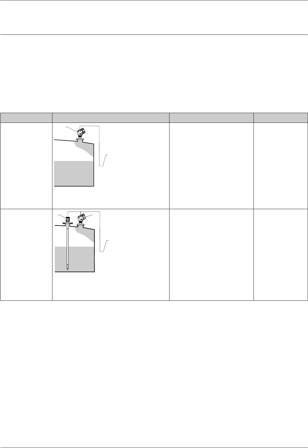
Direct level measurement
If no advanced tank measurement methods have been selected, level and temperature are measured
directly.
Direct level measurement modes
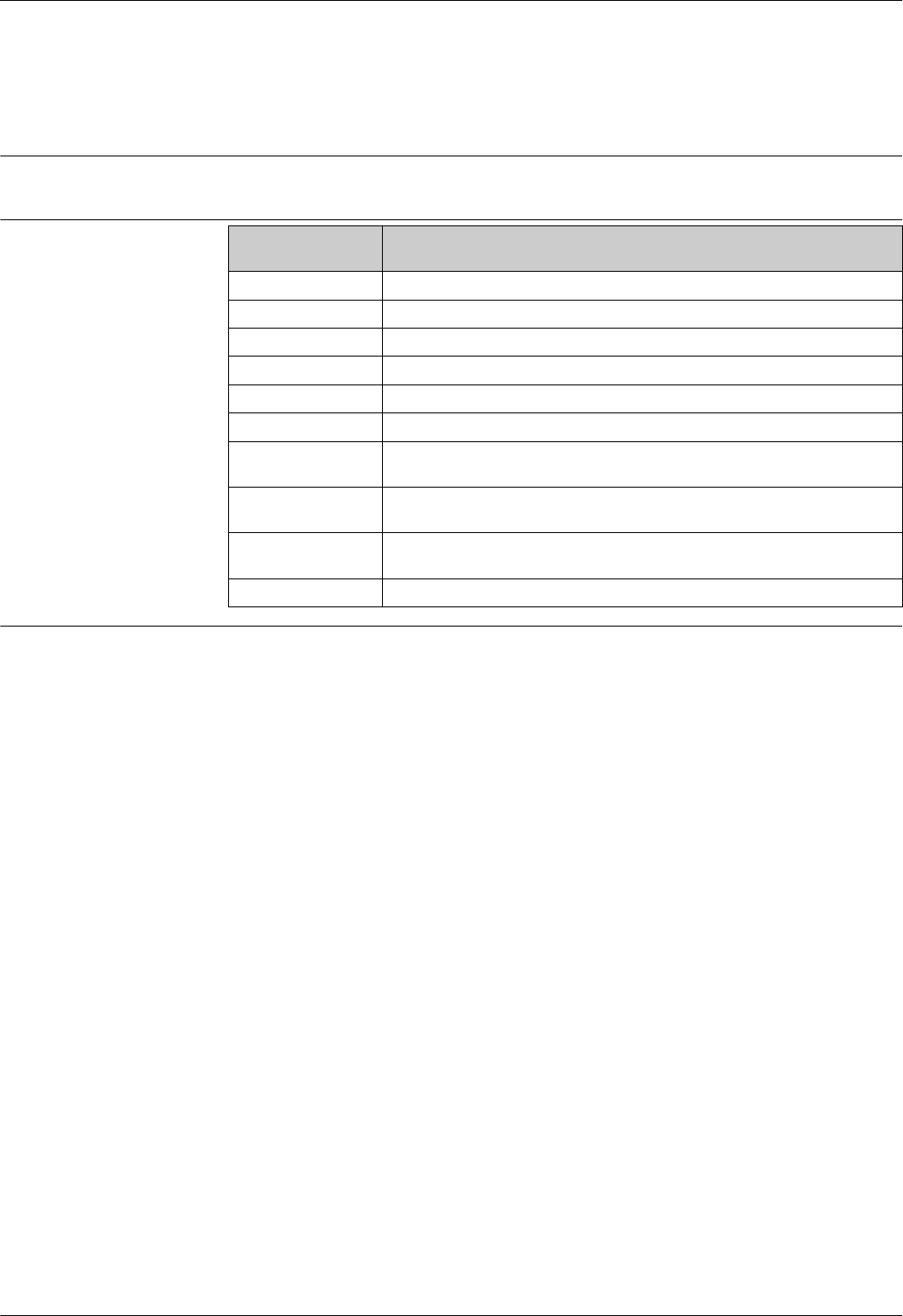
Measuring mode Installation example Measured variables Calculated variables
Level only
1
2
A0027111
1 Micropilot
2 To inventory management system
Level None
Level + temperature
3 1
2
A0027112
1 Micropilot
2 To inventory management system
3 Temperature transmitter (point or average)
• Level
•Temperature (point or average)
None
Micropilot NMR81
Endress+Hauser 35
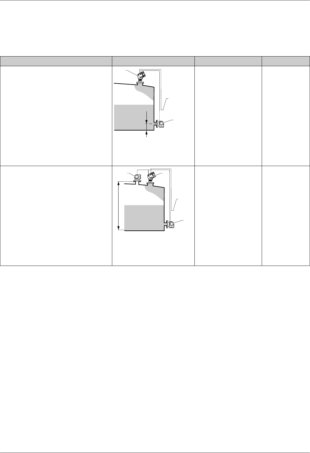
Hybrid tank measurement system (HTMS)
HTMS uses level and pressure measurements to calculate the contents of the tank and (optionally)
the density of the medium.
HTMS measuring modes
Measuring mode Installation example Measured variables Calculated variables
HTMS + P1
This mode should be used in atmospheric (i.e.
non-pressurized) tanks
3
D1
1
2
A0027113
1 Micropilot
2 To inventory management system
3 Pressure transmitter (bottom)
• Level
•Bottom pressure (at position
D1)
Density of the
medium
HTMS + P1 + P3
This mode should be used in non- atmospheric
(i.e. pressurized) tanks
3
4 1
D3
2
A0027114
1 Micropilot
2 To inventory management system
3 Pressure transmitter (bottom)
4 Pressure transmitter (top)
• Level
•Bottom pressure (at position
D1)
• Top pressure (at position
D3)
Density of the
medium
Micropilot NMR81
36 Endress+Hauser
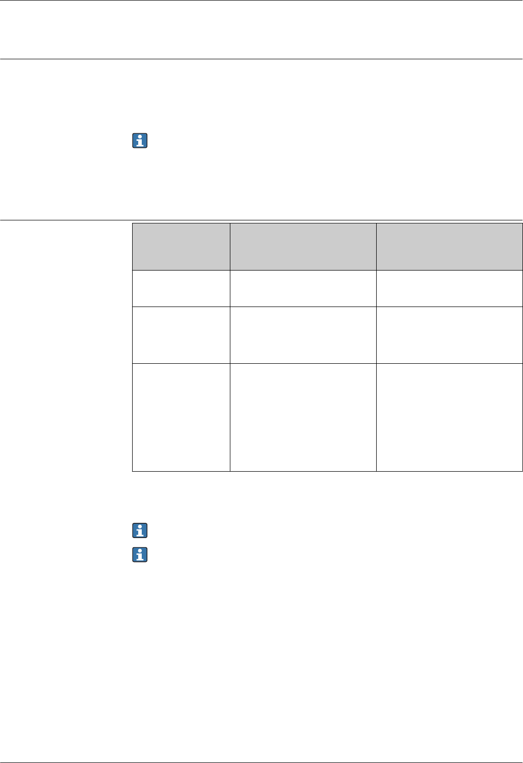
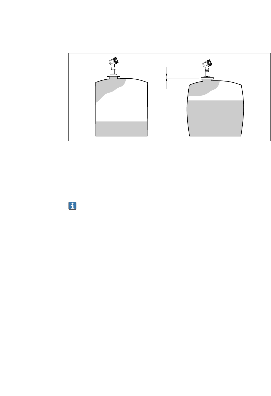
Hydrostatic tank shell correction (HyTD)
The hydrostatic tank shell correction can be used to compensate for vertical movement of the Gauge
Reference Height due to bulging of the tank shell caused by the hydrostatic pressure exerted by the
liquid stored in the tank. The compensation is based on a linear approximation obtained from
manual hand dips at several levels distributed over the full range of the tank.
Δx
A0023774
15 Movement Δx of the Gauge Reference Height due to the bulging of the tank shell caused by hydrostatic
pressure
Thermal tank shell correction (CTSh)
The thermal tank shell correction can be used to compensate for vertical movement of the Gauge
Reference Height due to temperature effects on the tank shell or stilling well. The calculation is
based on the thermal expansion coefficients of steel and on insulation factors for both the dry and
wetted part of the tank shell.
This correction is recommended for any tank gauge operating at conditions deviating
considerably from the conditions during calibration and for extremely high tanks. For
refrigerated, cryogenic and heated applications this correction is highly recommended.
Micropilot NMR81
Endress+Hauser 37
Accessories
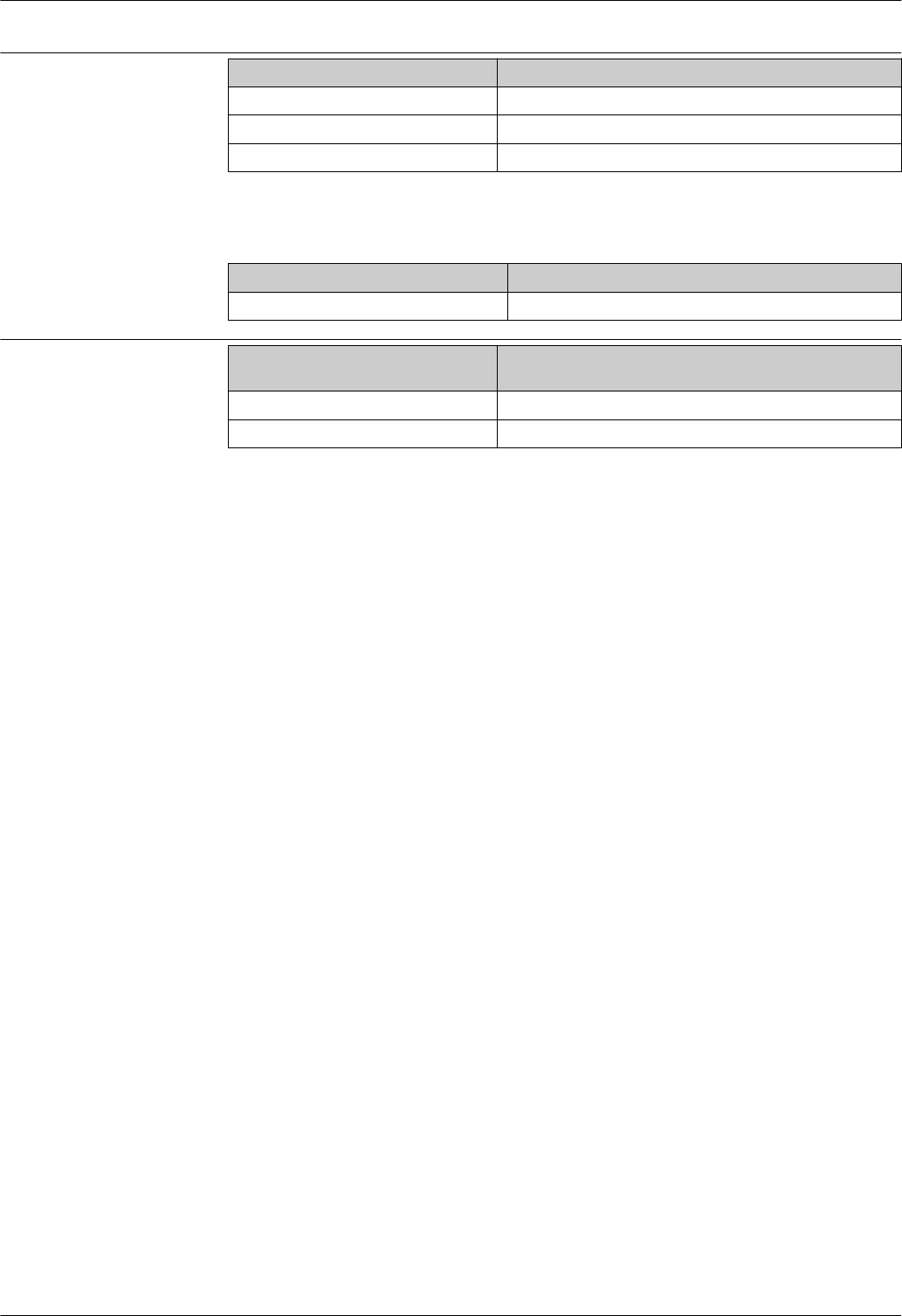
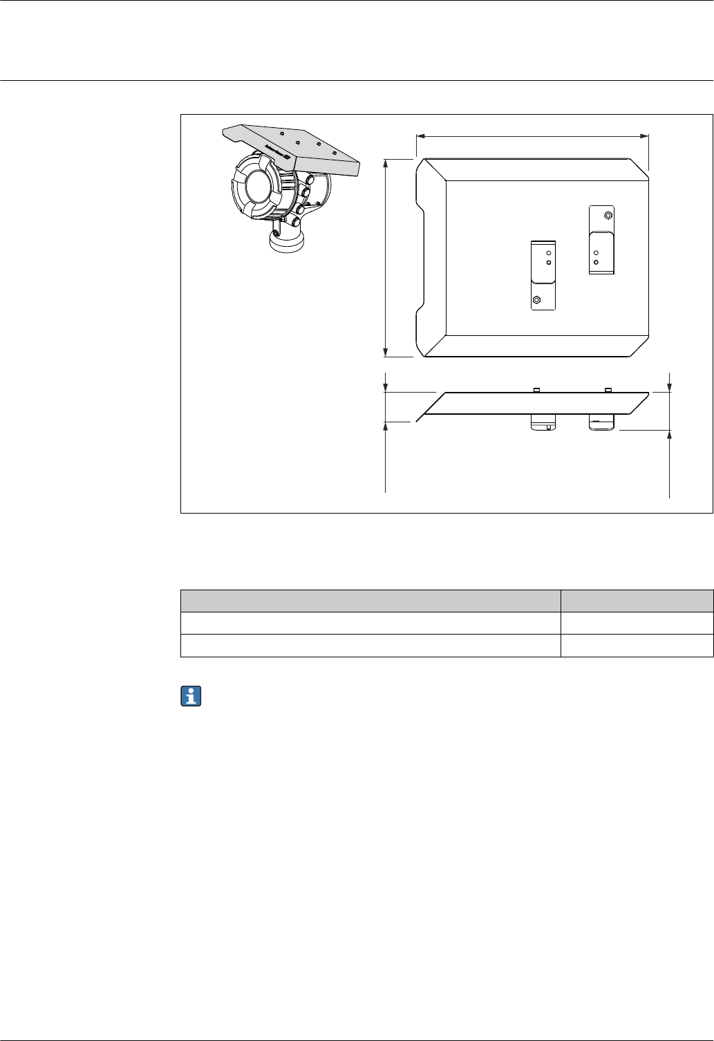
Device-specific accessories Weather protection cover
56.1 (2.21)
32.5 (1.28) 319 (12.6)
361.6 (14.2)
A0028019
16 Weather protection cover; dimensions: mm (in)
Materials
Part Material
Protection cover and mounting brackets 316L (1.4404)
Screws and washers A4
The weather protection cover can be ordered together with the device (ordering feature 620
"Accessory Enclosed", option PA "Weather Protection Cover") or as an accessory.
Micropilot NMR81
38 Endress+Hauser
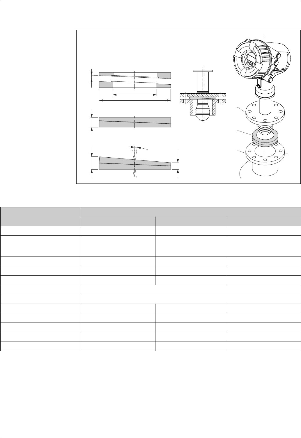
Adjustable seal
h
2
3
1
4°
øD
ød
hmax
hmin
±8°
A0027787
17 Adjustable seal used to align the device by ±8 °
Property Ordering feature 620 "Accessory Enclosed" 1)
PS PT PU
Order code 2) 71285499 71285501 71285503
Compatible with • DN50 PN10-40
•ASME 2" 150lbs
• JIS 50A 10K
DN80 PM10-40 • ASME 3" 150lbs
• JIS 80A 10K
Length of screws 100 mm (3.9 in) 100 mm (3.9 in) 100 mm (3.9 in)
Size of screws M14 M14 M14
Material FKM FKM FKM
Process pressure –0.1 to +0.1 bar (–1.45 to +1.45 psi)
Process temperature –40 to +80 °C (–40 to +176 °F)
ØD 105 mm (4.13 in) 142 mm (5.59 in) 133 mm (5.24 in)
Ød 60 mm (2.36 in) 89 mm (3.5 in) 89 mm (3.5 in)
h 16.5 mm (0.65 in) 22 mm (0.87 in) 22 mm (0.87 in)
hmin 9 mm (0.35 in) 14 mm (0.55 in) 14 mm (0.55 in)
hmax 24 mm (0.95 in) 30 mm (1.18 in) 30 mm (1.18 in)
1) With this ordering feature the adjustable seal is supplied together with the device.
2) This order code must be used if the adjustable seal is ordered separately.

Micropilot NMR81
Endress+Hauser 39
Communication-specific
accessories Accessory Description
Commubox FXA195
HART
For intrinsically safe HART communication with FieldCare via the USB interface.
For details refer to Technical Information TI00404F
Accessory Description
Commubox FXA291 Connects Endress+Hauser field devices with CDI interface (= Endress+Hauser
Common Data Interface) to the USB interface of a computer.
For details refer to Technical Information TI00405C
Accessory Description
WirelessHART Adapter
SWA70
Connects field devices to a WirelessHART network.
The WirelessHART adapter can be mounted directly at a HART device and is easly
integrated into an existing HART network. It ensures safe data transmission and
can be operated in parallel with other wireless networks.
For details refer to Operating Instructions BA00061S
Accessory Description
Fieldgate FXA320 Gateway for remote monitoring of connected 4-20mA measuring devices via web
browser.
For details refer to Technical Information TI00025S and Operating
Instructions BA00053S
Accessory Description
Fieldgate FXA520 Gateway for remote diagnosis and parametrization of connected HART measuring
devices via web browser.
For details refer to Technical Information TI00025S and Operating
Instructions BA00051S
Service-specific accessories Accessory Description
FieldCare Endress+Hauser's FDT-based Plant Asset Management tool.
Helps to configure and maintain all field devices of your plant. By supplying status
information it also supports the diagnosis of the devices.
For details refer to Operating Instructions BA00027S and BA00059S.
System components Accessory Description
RIA15 Compact process display unit with very low voltage drop for universal use to display
4 to 20 mA/HART signals
For details refer to Technical Information TI01043K.
Tankvision
•Tank Scanner NXA820
• Data Concentrator
NXA821
• Host Link NXA822
Inventory Management System with completely integrated software for operation
via standard web browser
For details refer to Technical Information TI00419G.
Micropilot NMR81
40 Endress+Hauser
Documentation
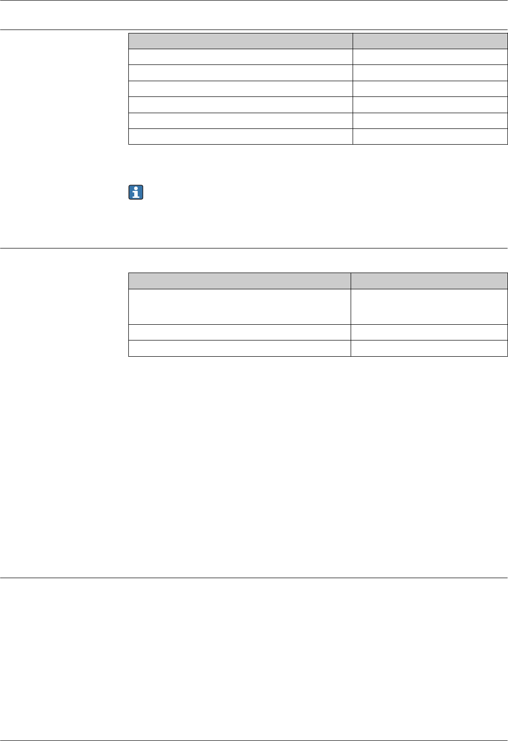
Technical Information (TI) The Technical Information contains all the technical data on the device and provides an overview of
the accessories and other products that can be ordered for the device.
Device Technical Information
Micropilot NMR81 TI01252G
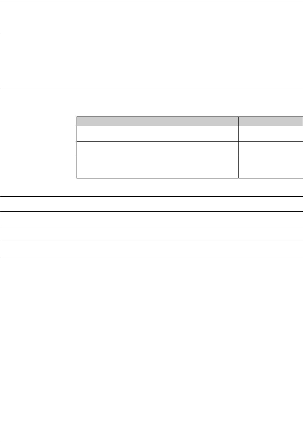
Brief Operating Instructions
(KA)
The Brief Operating Instructions contain all the essential information from incoming acceptance to
initial commissioning.
Device Brief Operating Instructions
Micropilot NMR81 KA01194G
Operating Instructions (BA) The Operating Instructions contain all the information that is required in various phases of the life
cycle of the device: from product identification, incoming acceptance and storage, to mounting,
connection, operation and commissioning through to troubleshooting, maintenance and disposal.
It also contains a detailed explanation of each individual parameter in the operating menu (except
the Expert menu). The description is aimed at those who work with the device over the entire life
cycle and perform specific configurations.
Device Operating Instructions
Micropilot NMR81 BA01450G
Description of Device
Parameters (GP)
The Description of Device Parameters provides a detailed explanation of each individual parameter in
the 2nd part of the operating menu: the Expert menu. It contains all the device parameters and
allows direct access to the parameters by entering a specific code. The description is aimed at those
who work with the device over the entire life cycle and perform specific configurations.
Description of Device Parameters (GP) for Micropilot NMR81
Device Description of Device Parameters
Micropilot NMR81 GP01068G (in preparation)
Safety instructions (XA) Ordering feature 010
"Approval"
Meaning XA
BE • ATEX II 1/2 G Ex ia/db IIC T4...T1 Ga/Gb
•ATEX II 2 (1) G Ex db [ia Ga] IIC T4...T1 Gb
XA01410G (in preparation)
FE FM C/US XP-AIS Cl.I Div.1 Gr.A-D, AEx d[ia] IIC T4...T1 XA01436G (in preparation)
IE • IECEx Ex ia/db IIC T4...T1 Ga/Gb
• IECEx Ex db [ia Ga] IIC T4...T1 Gb
XA01410G (in preparation)

Micropilot NMR81
Endress+Hauser 41
Registered trademarks
FieldCare®
Registered trademark of the Endress+Hauser Process Solutions AG, Reinach, Switzerland
MODBUS®
Registered trademark of the MODBUS-IDA, Hopkinton, MA, USA


www.addresses.endress.com
*unbekannt*