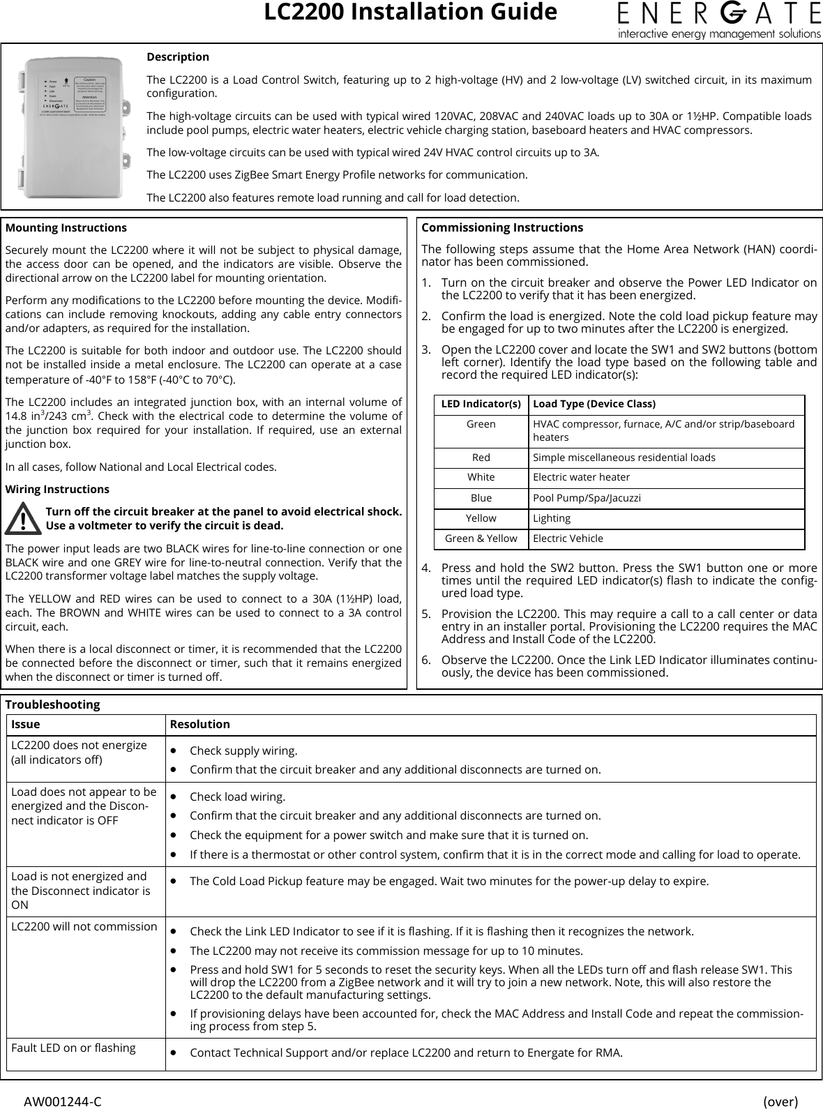
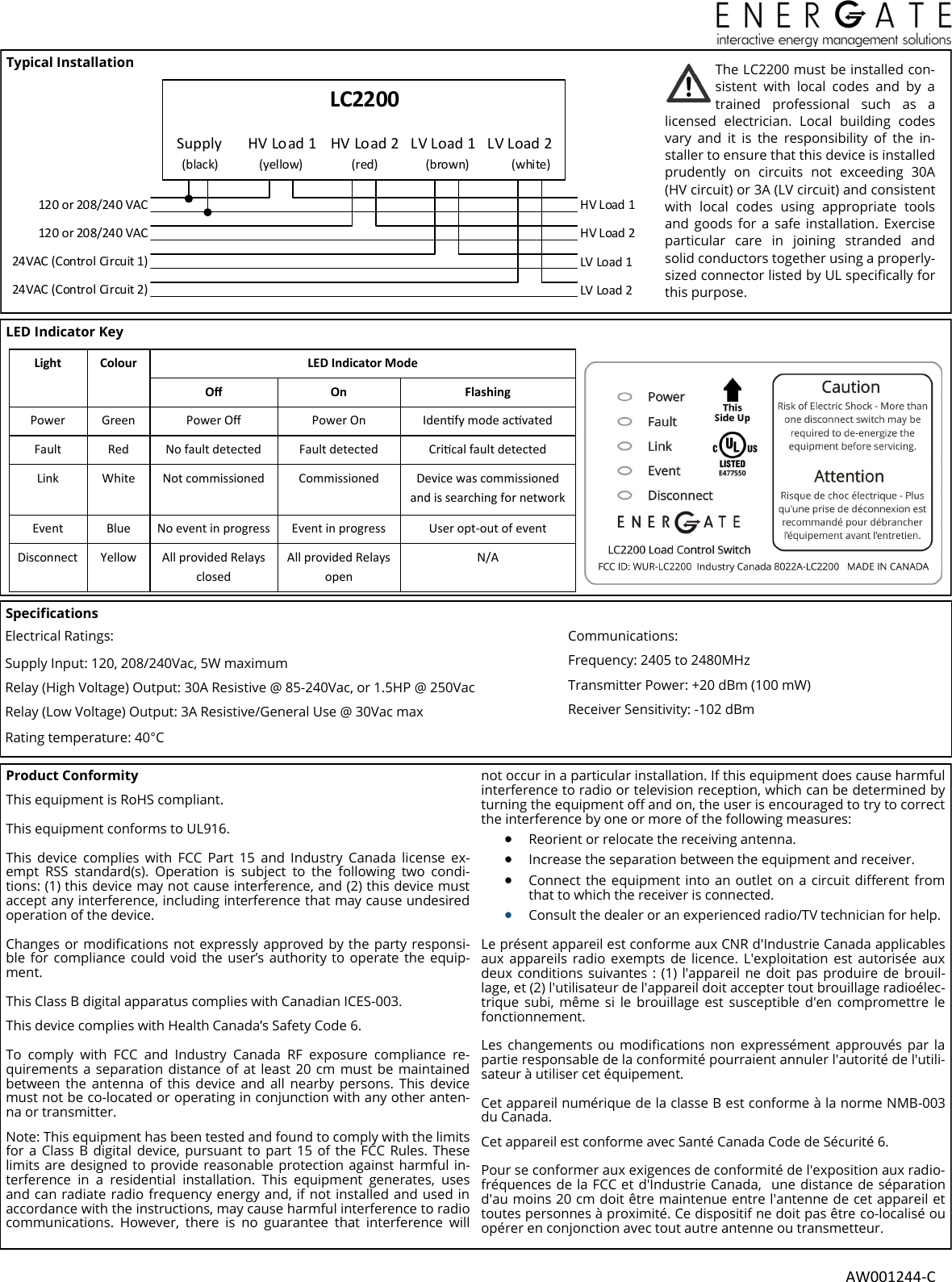
Energate LC2200 LC2200 Load Control Switch User Manual

Energate Inc. LC2200 Load Control Switch

User Manual

 AW001244-C    (over) LC2200 Installation Guide Description The LC2200 is a Load Control Switch, featuring up to 2 high-voltage (HV) and 2  low-voltage (LV) switched circuit, in its maximum conguration. The high-voltage circuits can be used with typical wired 120VAC, 208VAC and 240VAC loads up to 30A or 1½HP. Compatible loads include pool pumps, electric water heaters, electric vehicle charging station, baseboard heaters and HVAC compressors.  The low-voltage circuits can be used with typical wired 24V HVAC control circuits up to 3A.   The LC2200 uses ZigBee Smart Energy Prole networks for communication. The LC2200 also features remote load running and call for load detection. Mounting Instructions Securely mount the LC2200 where it will not be subject to physical damage, the  access door  can be  opened, and  the  indicators  are  visible.  Observe  the directional arrow on the LC2200 label for mounting orientation.  Perform any modications to the LC2200 before mounting the device. Modi-cations can  include  removing knockouts,  adding any  cable  entry connectors and/or adapters, as required for the installation. The LC2200 is suitable for both indoor and outdoor use. The LC2200 should not be installed inside a metal enclosure. The LC2200 can operate at a case temperature of -40°F to 158°F (-40°C to 70°C). The  LC2200 includes  an  integrated  junction box,  with  an  internal  volume  of 14.8 in3/243 cm3. Check with the electrical code  to determine the volume of the  junction  box  required  for  your  installation.  If  required,  use  an  external junction box. In all cases, follow National and Local Electrical codes. Wiring Instructions Turn o the circuit breaker at the panel to avoid electrical shock. Use a voltmeter to verify the circuit is dead. The power input leads are two BLACK wires for line-to-line connection or one BLACK wire and one GREY wire for line-to-neutral connection. Verify that the LC2200 transformer voltage label matches the supply voltage. The  YELLOW  and  RED  wires  can  be  used  to  connect  to  a  30A  (1½HP)  load, each. The BROWN and WHITE wires can be  used to  connect  to a  3A control circuit, each.  When there is a local disconnect or timer, it is recommended that the LC2200 be connected before the disconnect or timer, such that it remains energized when the disconnect or timer is turned o. Commissioning Instructions The following steps assume that the Home Area Network (HAN) coordi-nator has been commissioned. 1. Turn on the circuit breaker and observe the Power LED Indicator on the LC2200 to verify that it has been energized.  2. Conrm the load is energized. Note the cold load pickup feature may be engaged for up to two minutes after the LC2200 is energized. 3. Open the LC2200 cover and locate the SW1 and SW2 buttons (bottom left corner).  Identify the load type based on the following table and record the required LED indicator(s):  4. Press and hold the SW2 button. Press the SW1 button one or more times until the required LED indicator(s) ash to indicate the cong-ured load type. 5. Provision the LC2200. This may require a call to a call center or data entry in an installer portal. Provisioning the LC2200 requires the MAC Address and Install Code of the LC2200. 6. Observe the LC2200. Once the Link LED Indicator illuminates continu-ously, the device has been commissioned.  LED Indicator(s)  Load Type (Device Class) Green HVAC compressor, furnace, A/C and/or strip/baseboard heaters Red Simple miscellaneous residential loads White Electric water heater Blue Pool Pump/Spa/Jacuzzi Yellow Lighting Green & Yellow Electric Vehicle Troubleshooting Issue Resolution LC2200 does not energize (all indicators o)   Check supply wiring.   Conrm that the circuit breaker and any additional disconnects are turned on. Load does not appear to be energized and the Discon-nect indicator is OFF   Check load wiring.   Conrm that the circuit breaker and any additional disconnects are turned on.   Check the equipment for a power switch and make sure that it is turned on.   If there is a thermostat or other control system, conrm that it is in the correct mode and calling for load to operate. Load is not energized and the Disconnect indicator is ON   The Cold Load Pickup feature may be engaged. Wait two minutes for the power-up delay to expire. LC2200 will not commission   Check the Link LED Indicator to see if it is ashing. If it is ashing then it recognizes the network.   The LC2200 may not receive its commission message for up to 10 minutes.   Press and hold SW1 for 5 seconds to reset the security keys. When all the LEDs turn o and ash release SW1. This will drop the LC2200 from a ZigBee network and it will try to join a new network. Note, this will also restore the LC2200 to the default manufacturing settings.   If provisioning delays have been accounted for, check the MAC Address and Install Code and repeat the commission-ing process from step 5.   Fault LED on or ashing   Contact Technical Support and/or replace LC2200 and return to Energate for RMA.
     AW001244-CTypical Installation  Product Conformity  This equipment is RoHS compliant.  This equipment conforms to UL916.  This  device  complies  with  FCC  Part  15  and  Industry  Canada  license  ex-empt  RSS  standard(s).  Operation  is  subject  to  the  following  two  condi-tions: (1) this device may not cause interference, and (2) this device must accept any interference, including interference that may cause undesired operation of the device.  Changes or modications not expressly approved by the party responsi-ble  for compliance  could  void the  user’s authority to  operate the equip-ment.  This Class B digital apparatus complies with Canadian ICES-003. This device complies with Health Canada’s Safety Code 6.   To  comply  with  FCC  and  Industry  Canada  RF  exposure  compliance  re-quirements a separation distance of  at least 20  cm  must be  maintained between  the  antenna  of  this  device  and  all  nearby  persons.  This  device must not be co-located or operating in conjunction with any other anten-na or transmitter. Note: This equipment has been tested and found to comply with the limits for a Class  B  digital  device,  pursuant  to  part 15 of  the  FCC Rules. These limits are  designed to  provide reasonable  protection against harmful in-terference  in  a  residential  installation.  This  equipment  generates,  uses and can radiate radio frequency energy and, if not installed and used in accordance with the instructions, may cause harmful interference to radio communications.  However,  there  is  no  guarantee  that  interference  will not occur in a particular installation. If this equipment does cause harmful interference to radio or television reception, which can be determined by turning the equipment o and on, the user is encouraged to try to correct the interference by one or more of the following measures:   Reorient or relocate the receiving antenna.   Increase the separation between the equipment and receiver.   Connect the  equipment into an outlet on a circuit dierent  from that to which the receiver is connected.   Consult the dealer or an experienced radio/TV technician for help.  Le présent appareil est conforme aux CNR d'Industrie Canada applicables aux  appareils  radio  exempts  de licence.  L'exploitation est  autorisée  aux deux  conditions suivantes : (1)  l'appareil  ne doit pas produire  de brouil-lage, et (2) l'utilisateur de l'appareil doit accepter tout brouillage radioélec-trique  subi,  même  si  le  brouillage  est  susceptible  d'en  compromettre le fonctionnement.  Les  changements  ou  modications  non  expressément approuvés  par  la partie responsable de la conformité pourraient annuler l'autorité de l'utili-sateur à utiliser cet équipement.  Cet appareil numérique de la classe B est conforme à la norme NMB-003 du Canada. Cet appareil est conforme avec Santé Canada Code de Sécurité 6.   Pour se conformer aux exigences de conformité de l'exposition aux radio-fréquences de la FCC et d'Industrie Canada,   une distance de séparation d'au moins 20 cm doit être maintenue entre l'antenne de cet appareil et toutes personnes à proximité. Ce dispositif ne doit pas être co-localisé ou opérer en conjonction avec tout autre antenne ou transmetteur. Specications     Colour LED Indicator Mode Light O On Flashing Power Green Power O Power On Idenfy mode acvated Fault Red No fault detected Fault detected Crical fault detected Link White Not commissioned Commissioned Device was commissioned and is searching for network Event Blue  No event in progress Event in progress User opt-out of event Disconnect Yellow All provided Relays closed All provided Relays open N/A LED Indicator Key The LC2200 must be installed con-sistent  with  local  codes  and  by  a trained  professional  such  as  a licensed  electrician.  Local  building  codes vary  and  it  is  the  responsibility  of  the  in-staller to ensure that this device is installed prudently  on  circuits  not  exceeding  30A (HV circuit) or 3A (LV circuit) and consistent with  local  codes  using  appropriate  tools and  goods  for  a  safe  installation. Exercise particular  care  in  joining  stranded  and solid conductors together using a properly-sized connector listed by UL specically for this purpose. HV Load 1HV Load 2LV Load 1LV Load 2LC2200Supply HV Load 1    HV Load 2   LV Load 1   LV Load 2    (black)         (yellow)               (red)                (brown)              (white)120 or 208/240 VAC120 or 208/240 VAC24VAC (Control Circuit 1)24VAC (Control Circuit 2)Electrical Ratings: Supply Input: 120, 208/240Vac, 5W maximum Relay (High Voltage) Output: 30A Resistive @ 85-240Vac, or 1.5HP @ 250Vac Relay (Low Voltage) Output: 3A Resistive/General Use @ 30Vac max Rating temperature: 40°C  Communications: Frequency: 2405 to 2480MHz Transmitter Power: +20 dBm (100 mW) Receiver Sensitivity: -102 dBm

Navigation menu