EnergyICT NV RTUS2-WC DATA CONCENTRATOR COLLECTING METER DATA OVER WAENIS RF NETWORK User Manual EMNL000057 01 EN EVOGate 2 0
EnergyICT NV DATA CONCENTRATOR COLLECTING METER DATA OVER WAENIS RF NETWORK EMNL000057 01 EN EVOGate 2 0
USERS MANUAL

EVOGate 2.0
with RTU+Server2
Installation Manual
Serial Number
Document Code
EMNL000057_01_EN EVOGate 2.0
2 / 29
Copyright
EnergyICT n.v. Copyright 2011 by EnergyICT n.v. All rights reserved. The information in this document is subject to change
without notice and does not represent a commitment on the part of EnergyICT. The software described in this document is
furnished under a license agreement, and may be used or copied only in accordance with the terms of that agreement. No part
of this document may be reproduced, transmitted, transcribed, stored in any retrieval system, or translated into any language
by any means, electronic or mechanical, including photocopying and recording, for any purpose other than the licensee's
personal use without the express written permission of EnergyICT. In no event will EnergyICT be responsible for any damages,
including any lost profits, lost savings or other incidental or consequential damages arising out of the use of this product.
Disclaimer
The information contained in this message (including any attachments) is confidential and intended solely for the attention and
use of the named addressee(s). It must not be disclosed to any person without our authority. If you are not the intended
recipient, please delete it from your system immediately - any disclosure, copying or distribution thereof or any action taken or
omitted to be taken in reliance thereon is prohibited and may be unlawful.
3 / 29
Table of contents
Safety Precautions ........................................................................................................................................4
Notice on Interference ..................................................................................................................................5
Chapter 1: Introduction ........................................................................................................ 6
About the EVOGate 2.0 .................................................................................................................................7
EVOGate 2.0 Component Overview ...............................................................................................................8
Technical Specifications ..............................................................................................................................10
RTU+Server2 Casing...................................................................................................................................11
IP Enclosure Casing ....................................................................................................................................12
RTU+Server2 Labels ...................................................................................................................................14
IP Enclosure Labels.....................................................................................................................................16
LED Indications...........................................................................................................................................19
Chapter 2: Mounting and Wiring......................................................................................... 20
Mounting Instructions IP Enclosure .............................................................................................................21
Power Supply Wiring Safety Guidelines........................................................................................................21
Power Supply Wiring Instructions EVOGate 2.0............................................................................................22
Power Supply Wiring RTU+Server2 .............................................................................................................23
Chapter 3: Communication Interfaces................................................................................ 24
Overview Communication Interfaces............................................................................................................25
Double Ethernet Connection........................................................................................................................26
Double USB 2.0 Host Connection.................................................................................................................26
GSM/GPRS Modem......................................................................................................................................27
Wavenis RF Modem ....................................................................................................................................28
Appendix ............................................................................................................................. 29
4 / 29
Safety Precautions
Precautions The EVOGate 2.0 with RTU+® Server2 has been designed and tested with US
norms and has left the factory in a safe condition. The present installation manual
contains important information and warnings which have to be followed by the
user to ensure safe operation and to retain the unit in safe condition.
Interventions Any interventions to the EVOGate 2.0 with RTU+® Server2 must be done by
technical service staff only.
Note
+ Changes or modifications not expressly approved by the responsible party
for compliance (EnergyICT®) could void the user's authority to operate the
equipment.
Clock The device contains a real-time clock with 6 day autonomy in case of absence of
power.
WARNING! When activating the Wavenis modem, an RF antenna must already be connected
to the EVOGate 2.0! The absence of an antenna during activation will cause
irreparable damage to the modem.
Consult “Wavenis RF Modem” on page 27 for more information.
5 / 29
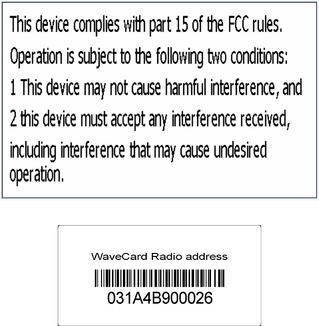
Notice on Interference
FCC The EVOGate 2.0 complies with Part 15 of the FCC Rules / Industry Canada license-
exempt RSS standard(s). Operation is subject to the following two conditions: (1)
this device may not cause harmful interference, and (2) this device must accept any
interference received, including interference that may cause undesired operation.
Class B digital
device
This Class B digital apparatus complies with Canadian ICES-003.
Use of radio
frequency
energy
This device generates, uses and can radiate radio frequency energy and, if not
installed and used in accordance with the instructions, may cause harmful
interference to radio communications.
However, there is no guarantee that interference will not occur in a particular
installation.
Preventing
interference
If this equipment does cause harmful interference to radio or television reception,
which can be determined by turning the equipment off and on, the user is
encouraged to try to correct the interference by one or more of the following
measures:
+ Reorient or relocate the receiving antenna
+ Increase the distance between the equipment and the receiver
+ Connect the equipment into an outlet on a circuit different from that to which
the receiver is connected.
+ Consult the dealer or an experienced radio/TV technician for help.
Notice on Industry Canada (IC) certification
Under Industry Canada regulations, this radio transmitter may only operate using an antenna of a type
and maximum (or lesser) gain approved for the transmitter by Industry Canada. To reduce potential
radio interference to other users, the antenna type and its gain should be so chosen that the equivalent
isotropically radiated power (e.i.r.p.) is not more than that necessary for successful communication.
This radio transmitter (IC: 9864A-RTUS2WC) has been approved by Industry Canada to operate with
the antenna types listed below with the maximum permissible gain and required antenna impedance for
each antenna type indicated. Antenna types not included in this list, having a gain greater than the
maximum gain indicated for that type, are strictly prohibited for use with this device
Antenna type used for certification measurements : Antenex FG9026
Antenna specs:
- Frequency range : 902 – 928 MHz
- VSWR : < 1.5:1 Max
- Nominal Gain : 6 dBd
- Nominal impedance : 50 Ohm
- Polarization : vertical

6 / 29
Chapter 1: Introduction
Introduction This chapter provides the user with an introduction to the EVOGate 2.0, its main
internal components (including EnergyICT’s RTU+ Server2 data concentrator) and
its main functions.
Chapter
description
This chapter describes the following topics:
Topic Page
About the EVOGate 2.0 [7]
EVOGate 2.0 Component Overview [8]
Technical Specifications [10]
RTU+Server2 Casing [11]
IP Enclosure Casing [12]
RTU+Server2 Labels [14]
IP Enclosure Labels [16]
LED Indications [18]

7 / 29
About the EVOGate 2.0
Description The EVOGate 2.0 is positioned as the generic ODM Water solution for utility
applications in the United States.
EVOGate 2.0’s main component is the RTU+ Server2 concentrator; which is built
around a core feature set and is provided with a robust casing. The RTU+ Server2
is installed inside the EVOGate 2.0’s IP enclosure resisting easily to any industrial
environment. The RTU+ Server2 also offers unprecedented upstream and
downstream flexibility and splits expensive communication over multiple endpoints,
allowing utilities to optimize the implementation of various AMI technologies.
Main functions
The table below lists the main functions of the RTU+ Server2:
Function Description
Data collection Data is collected and stored per definable interval
period; the device is able to store a virtually unlimited
amount of data, depending on its memory capacity. For
more information on memory capacity, see “Technical
Specifications” on page 10.
Pulse data is collected via the digital inputs and meter
data is collected via the standard serial interface or via
an optional communication interface.
Data transfer The RTU+ Server2 can transfer data to EnergyICT’s
advanced EIServer meter data management solution
using the EIWebp+ push protocol, via its Ethernet
ports, or via an optional communication interface.
Fixed network
management and
remote monitoring
The RTU+ Server2 has embedded network
management capability and serves as master
concentrator in a
Wavenis
RF network, with multiple
Wavenis endpoints acting as slaves. For more
information, see “Wavenis RF Modem” on page 27.
8 / 29
EVOGate 2.0 Component Overview
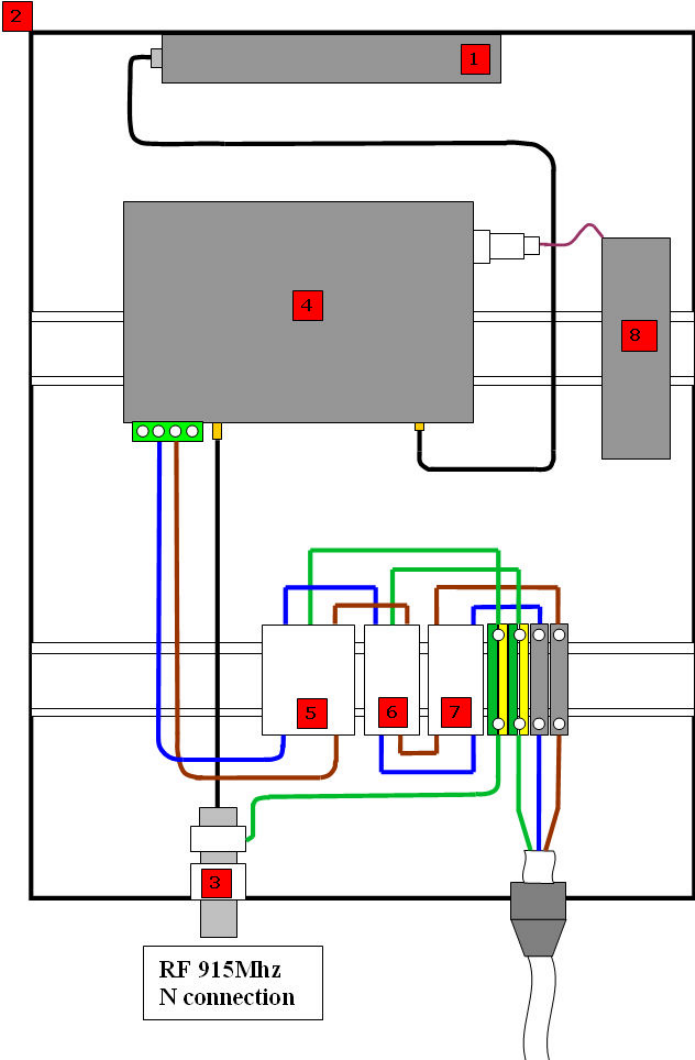
Overview Listed below are EVOGate 2.0’s main components.
The EVOGate 2.0 entails all components described here at purchase, except for the
Wavenis antenna (and coax cable) which need to be purchased separately. Consult
the Appendix for more information.

9 / 29
Description
Component Type
1. GSM Antenna CANT000021
2. IP Polyester enclosure Schneider Electric NSYPLM43
3. N-to-N Surge protection
Phoenix contact 2818148
4. Data concentrator DIN Rail mounted
RTU+Server2
5. Net Filter DIN Rail mounted
Phoenix contact 2788977
6. Surge Protector DIN Rail mounted
Phoenix contact 2856812
7. Automatic Fuse DIN Rail mounted
Phoenix contact 0916608
8. Battery CBAT000003
Important!
Battery may need to be installed by
the customer (application
dependent).

10 / 29
Technical Specifications
Feature Implementation
HOUSING IP Enclosure Housing Protection:
• IP 66
• Type NSYPLM43 (See p. 12 for more technical characteristics)
Internal RTU+Server2 Housing:
• Plastic enclosure 183 * 174 * 62 mm. (including optional connector cover)
• Material: PC ABS (UL94 5VA compliant)
• Fixation: DIN Rail connection
POWER • Universal Power Supply: 100 VAC - 230 VAC
BATTERY • Internal Lithium ion battery pack, based on GP Battery Swing 4400 Cells
• Usage: UPS functionality.
o When main power is cut, unit survives for maximum 6 days.
• Discharge temp: -40 °C - +65°C
• Charge temp: -10°C - +60°C
• Voltage: 7,4V / 12Ah
• Fuel Gauge circuit with I2C communication 5V signaling
• Configuration: 2S3P
• Recharging time: 24 to 48 hours
• Certification: UN3480
CONSUMPTION • Max. 6 VA
FUSE • 6 A
MEMORY
RTU+SERVER2
• 128 MByte SDRAM (32-bit wide)
•
256 MByte Managed NAND Flash (up to 2GByte on request). Memory extension is
not possible.
OPERATING
SYSTEM
• Linux
SOFTWARE • Plug and Play configured software cooperating with EIServer
• Data collection software with extended protocol library
SOFTWARE
UPGRADES
• via Ethernet
• via USB
• via GPRS (possible but not recommended)
TEMPERATURE • Extended temperature range from -20° C to +60° C
TAMPER
DETECTION
• Tamper contact via a “cover-
removed” alarm: when the internal cover is removed,
an alarm signal is sent to the meter data management platform.
CERTIFICATIONS • CCSAUS certified
• Emission: FCC Part 15, FCC ID : VS7RTUS2-WC / IC : 9864A-RTUS2WC
11 / 29
RTU+Server2 Casing
Overview
The RTU+ Server2 resides in a PC ABS UL94 5VA-compliant plastic enclosure. This
cover shields the motherboard and all internal components from the outside. 3 screws
are used to fasten this cover to the mounting plate.
Dimensions Plastic enclosure 183 * 174 * 62 mm.
12 / 29
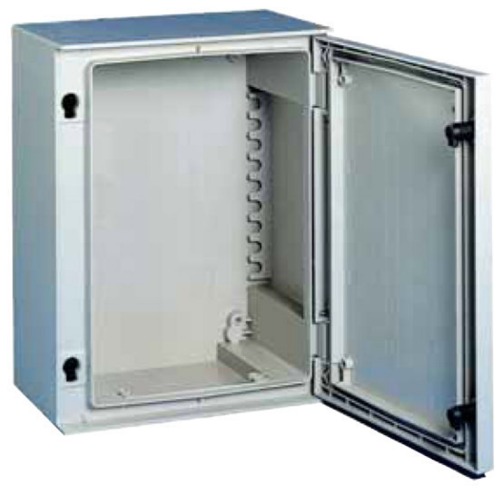
IP Enclosure Casing
Overview
The RTU+ Server2 and all EVOGate 2.0 components are mounted into a Polyester
wall-mounting enclosure IP 66 Type NSYPLM43:
Technical
specifications
• Monobloc wall-mounting enclosure made from polyester reinforced with
fiberglass, molded by hot compression, RAL 7032 grey color.
• Degree of protection IP 66 according to IEC 60529.
• Resistance to external mechanical impacts:
– Plain door enclosures IK 10 (20 joules).
• Locking device outside the sealed area, guaranteeing the tightness of IP 66
over time.
• Locking system:
– 2 locks with double-bar insert
• Door opening angle: 180°.
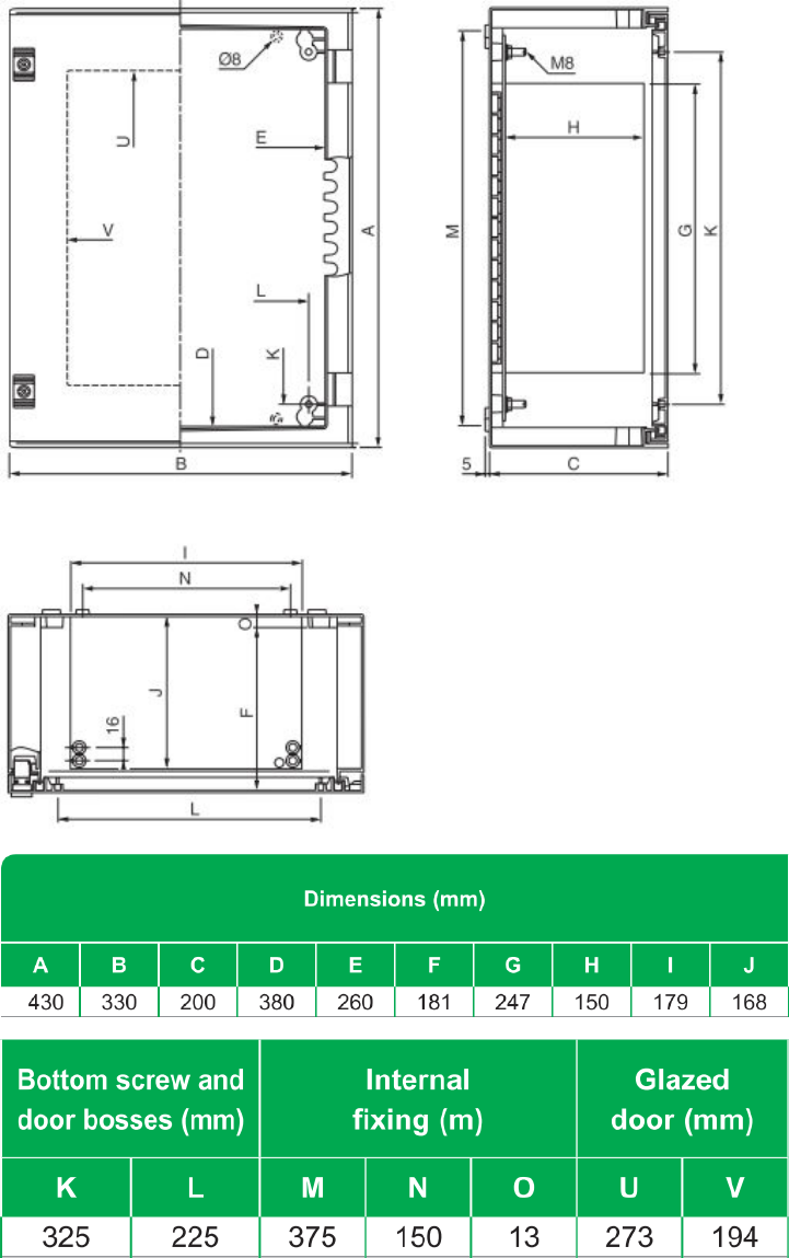
13 / 29
Dimensions
14 / 29
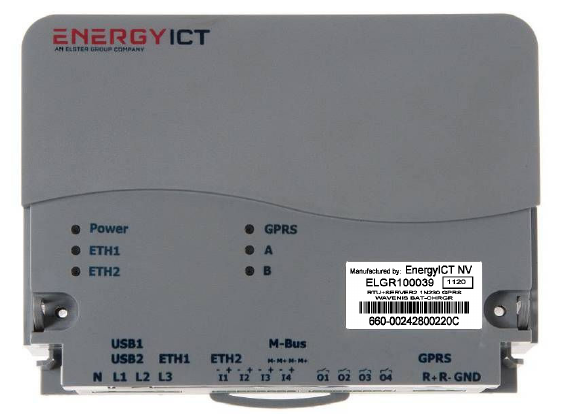
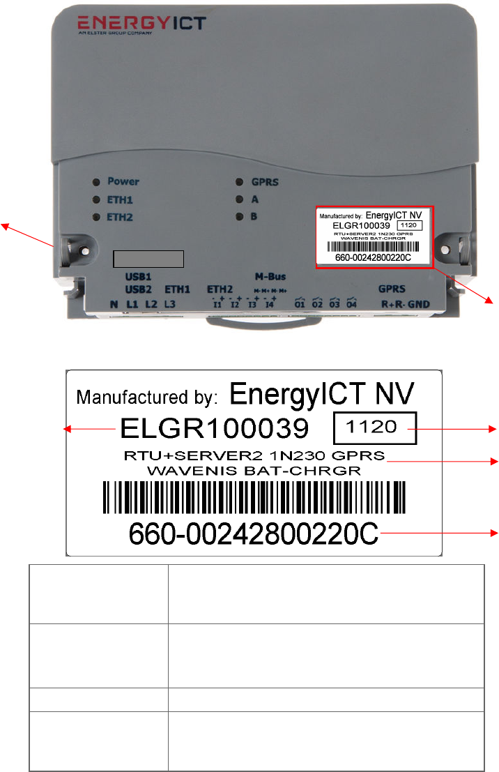
RTU+Server2 Labels
Overview The RTU+ Server2 has the following 2 labels located on its casing:
Label A This label contains the RTU+Server2’s article code and unique serial number:
1. Article code The code of the product.
Consult the Appendix for a full overview of available
product types, their article codes and spare parts.
2. Production Time
XXYY:
• XX: Production Year (last two digits of the
year)
• YY: Production Week
3. Description The description of the data concentrator
4. Serial number XXX – YYYYYYYYYYYY
• XXX: Family Type
• YYYYYYYYYYYY: Unique Serial Number
Label A
Label B
2
3
4
1
Max. 50 mA
15 / 29
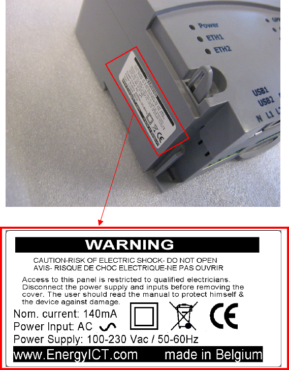
Label B This label depicts the power input specifications and warning content:
16 / 29
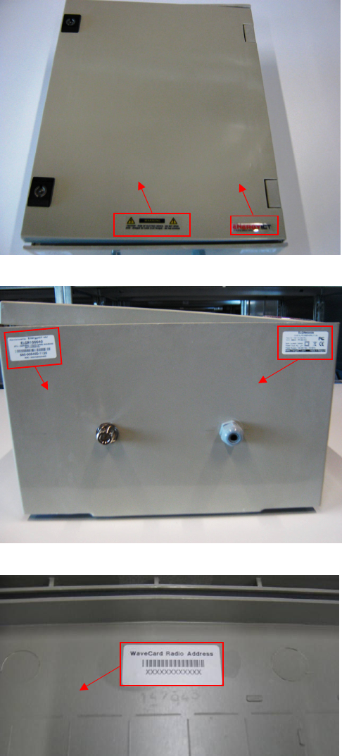
IP Enclosure Labels
Overview The IP enclosure has:
• 2 labels located on its front panel:
• 2 labels located on its bottom panel:
• 1 label located on the inside of its door:
Label C
Label D
Label E
Label F
Label G
17 / 29
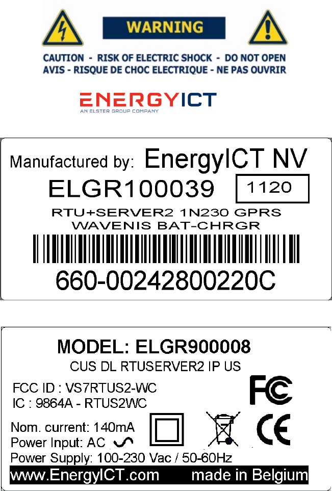
Label C Warning label:
Label D EnergyICT logo:
Label E Identical as Label A:
Label F The FCC and IC Label; also depicts the article number of the EVOGate 2.0:
18 / 29
Label G The WaveCard Radio address label:
19 / 29
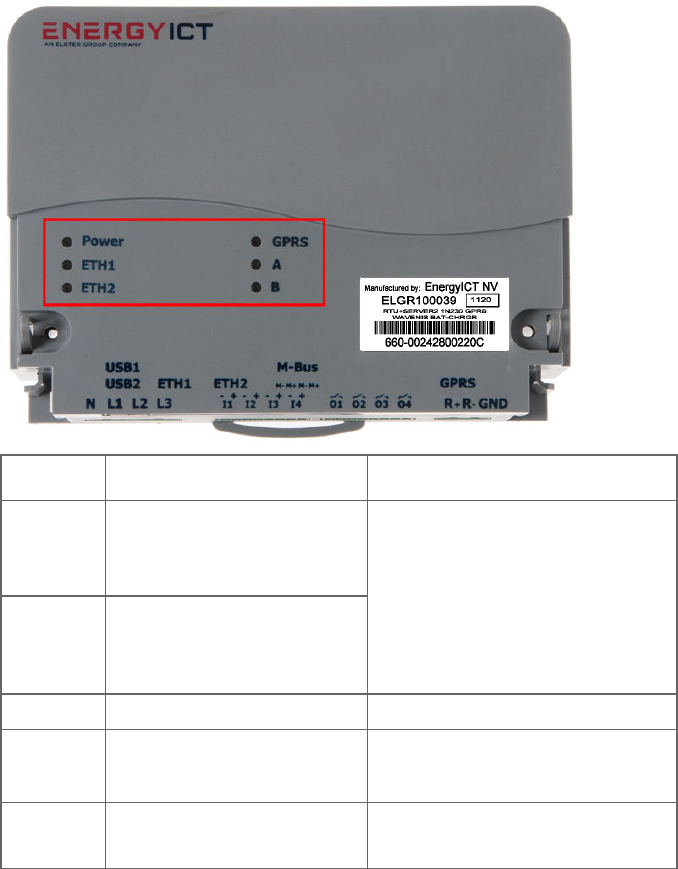
LED Indications
Introduction The RTU+Server2 data concentrator has 6 LEDs located on the top cover of the
enclosure.
Power Power LED ON when the unit is powered.
ETH1
1st Ethernet port LED.
ETH2 2nd Ethernet port LED.
- When OFF: no link integrity
(no cable connected)
- When ON: link integrity
(link with HUB)
- When blinking:
receiving data
GPRS GPRS LED ON when transmitting data
A Application Dependent - When blinking at 0.5Hz:
receiving data
B
Reserved Reserved

20 / 29
Chapter 2: Mounting and Wiring
Introduction This chapter provides information on the physical installation of the polyester
enclosure, including mounting and wiring instructions.
Chapter
description
This chapter describes the following topics:
Topic Page
Mounting Instructions IP Enclosure [20]
Power Supply Wiring Safety Guidelines [20]
Power Supply Wiring Instructions EVOGate 2.0 [21]
Power Supply Wiring RTU+Server2 [22]
21 / 29
Mounting Instructions IP Enclosure
Power Supply Wiring Safety Guidelines
Securing the
device
The RTU+Server2 concentrator is internally protected by fuse resistors. Power
rating: 2W. Fuse type : Welwyn Components ULW2-100RJA25
Wiring The following additional guidelines must be taken into account:
+ The unit must have a permanent connection to fixed wiring
+ The power supply must be connected to the power connector of the RTU+
Server2 by means of solid wiring.
Cables The concentrator was designed and tested to operate safely in an industrial and
residential environment. However, you must take care to use one of two options:
+ Shielded network cables (FTP cables)
+ Unshielded network cables (UTP cables)
Power
specifications
Power specifications are located on label B and label F, as mentioned under the
labels section on page 14 and 16.
Mounting the
IP Enclosure
The IP enclosure can be mounted directly on the walls. The seals and caps supplied as
standard with the enclosure guarantee that it maintains its degree of protection and
insulation.
There are 3 options:
• Wall-fixing lugs
• Post-fixing device
• Blanking Plates
Important!
Included in the EVOGate 2.0 package is a document which describes these options.
However, none of these options are part of the EVOGate package and need to be
purchased from Schneider. Please refer to the Schneider website to purchase these
options.
22 / 29
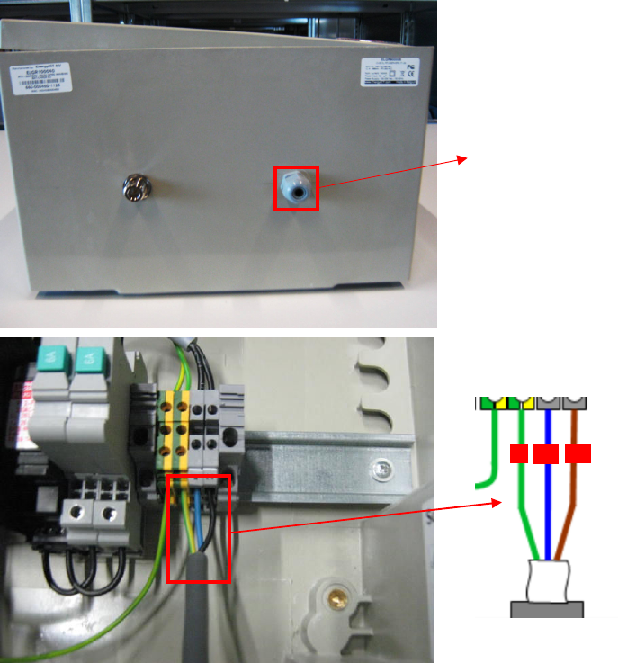
Power Supply Wiring Instructions EVOGate 2.0
Power
connector
The power supply cable gland is located to the right on the bottom panel of the
EVOGate 2.0’s enclosure. The cable gland only accepts AC input signals.
Power supply
wiring
connections
Connect the electrical wire to the cable gland carefully.
Power Supply
Cable Gland
G
L1
L2
23 / 29
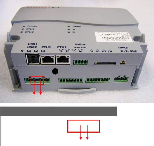
Power Supply Wiring RTU+Server2
Power
connector
The power supply connector is located at the bottom left corner of the RTU+
Server2. The connector only accepts AC input signals.
Single wire or
two wires
The connector accepts single wires of 0,2 to 2,5 mm² (24 to 14 AWG) or two wires
of 0,2 to 1,0 mm² (24 to 18 AWG).
Power supply
wiring
connections
Important!
The RTU+Server2 is already fully connected at EVOGate 2.0 purchase.
Circuit Physical Connection
2F 115V
L1 L2
L1 L2
x
x

24 / 29
Chapter 3: Communication Interfaces
Introduction The EnergyICT RTU+ Server2 is configured with a number of communication
interfaces for downstream communication to the meters as well as upstream
communication to a central data management system.
Chapter
description
This chapter contains information on the communication cards of the
RTU+Server2.
Important!
All communication interfaces are already in place at purchase; installation and
maintenance may only be carried out by qualified personnel.
Topic Page
Overview Communication Interfaces
[24]
Upstream
Double Ethernet Connection [25]
Double USB 2.0 Interface [25]
GSM/GPRS Modem [26]
Downstream
Wavenis RF Modem [27]
25 / 29
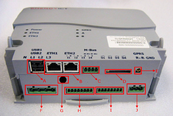
Overview Communication Interfaces
Description The overview of the RTU+ Server2 standard communication interfaces is shown
below:
A. Double USB connectors F. Power input connector
B. Double Ethernet connectors G. RF Wavenis antenna connector
C. Wired M-Bus connector
(Not Applicable)
H. Digital inputs
(Not Applicable)
D. SIM-card interface I. Digital outputs
(Not Applicable)
E. GSM/GPRS antenna connector J. RS-485 connector
(Not Applicable)
26 / 29
Double Ethernet Connection
Description The RTU+ Server2 uses the Ethernet 10/100 Base-T standard. Every unit features
2 standard Ethernet ports, as depicted below, and can be connected to a LAN
network using standard straight-through LAN RJ-45 connectors. Link Integrity and
Rx indication LEDs are located on the connector.
To make a direct connection to a PC, a crossover LAN cable should be used.
Double USB 2.0 Host Connection
Description The RTU+ Server2 uses the USB 2.0 standard. Every unit features 2 standard USB
interfaces, as depicted below, next to the Ethernet ports. Both connections can, for
example, be used to connect keyboards and memory sticks for software updates.
IMPORTANT USB ports may exclusively be used for service purposes.
A maximum of 50 mA is allowed.
USB devices must be removed during normal operation.
27 / 29
GSM/GPRS Modem
Description
This card equips the RTU+ Server2 with a high tech GSM/GPRS modem. This
allows collected data to be transmitted over the Internet without a need for a fixed
connection.
Note
+ The advanced GSM/GPRS EDGE modem is available on request: this
technology offers increased data transmission speeds and is supported by all
major providers.
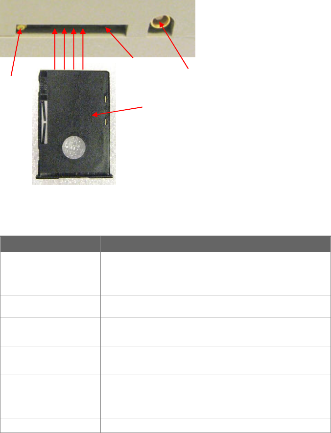
Installation
In order to function, the GSM/GPRS modem requires a SIM-card.
This SIM-card has to be placed inside a SIM-card holder A and placed inside B on
the modem itself, before switching on the RTU+ Server2. Next, the GSM-antenna
has to be screwed into C. Press D to eject the SIM-card holder.
Technical
specifications
Feature Implementation
Frequency
Bands
Quad-band module includes support for GSM 850 and
PCS 1900
Compliant to GSM Phase 2/2+
Transmit Power Class 1 (1W) at GSM 850 and PCS 1900
GPRS
Connectivity
GPRS multi-slot class 10
GPRS mobile station class B
Temperature
Range
Normal operation: -20°C to +60°C
GPRS
GPRS data downlink transfer: max. 85.6 kbps
GPRS data uplink transfer: max. 42.8 kbps
Coding scheme: CS-1, CS-2, CS-3 and CS-4
SIM Interface Supported SIM card: 1V8, 3V
B
C
A
D
28 / 29
Wavenis RF Modem
Description
This module empowers the RTU+ Server2 to serve as master in a Wavenis RF
network.
Wavenis is an integrated wireless communication application capable of high
performance network management and 2-way endpoint monitoring, remote data
collection and scheduled polling.
Communication management for extended networks is achieved via smart
gateways, repeaters and end-points.
Stored data is uploaded to EIServer via EnergyICT’s proprietary EIWeb+ protocol.
The RF module is embedded at the factory.
Important!:
• The Wavenis RF antenna and coax cable need to be ordered separately!
EnergyICT recommends the Antenex FG9026 as this was used for the
FCC / IC tests.
• When activating the Wavenis modem, an RF antenna must already be
connected to the EVOGate 2.0! The absence of an antenna during activation
will cause irreparable damage to the modem.
Consult the Appendix for more information.
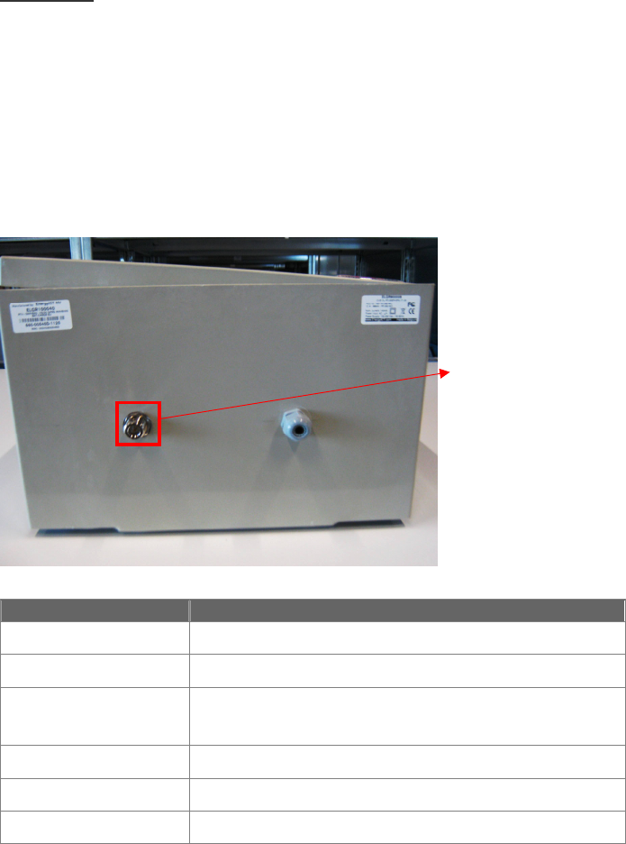
Antenna
connection
Technical
specifications
Feature Implementation
Frequency range 915 MHz
Output power Maximum +27 dBm (500 mW)
Receiver sensitivity (-110)dBm @ 19.2 kbps
(-113)dBm @ 4.8 kbps
Channels 16 channels (hopping)
Data rate Maximum: up tot 100 kbps
Range Outdoor: up to 1000 meters (line-of-sight)
Wavenis
Antenna
Connector

29 / 29
Appendix
Article
numbers
This number represents the code for the concentrator type. If you experience problems
with your concentrator or wish to purchase spare parts, please refer to the specific article
number:
Article Number Description
EVOGate 2.0
ELGR900008
RTU+Server2 + IP Enclosure + Wavenis 915Mhz
500mW US + Battery + Protection GPRS/GSM +
Protection Wavenis + Breaker + Filter + GPRS
Antenna + NO Wavenis Antenna
Antenex FG9026 Wavenis Antenna
(Needs to be purchased separately)
CCBL000033 Low loss coax cable, 10meter. N–male both sides
(Needs to be purchased separately)
Spare Parts
CBAT000003 Battery
CANT000021 GSM Antenna