Enersys 4C6567426F78 INDUSTRIAL BATTERY CONTROLLER LEGACYBOX User Manual installation instructions rev 0
Enersys Inc. INDUSTRIAL BATTERY CONTROLLER LEGACYBOX installation instructions rev 0
Enersys >
User Manual

Installation and setup of the Legacy box battery monitor device on motive power
batteries
1.0 Materials and Equipment
Appropriate Legacy box per section 2.0, with wire ties, level sensor grommet, ring terminals, and tapping screws
Noalox Antioxidant joint compound 1 oz container for single device installation– part #92634 or bottle for multiple
device installation – part # 828102
Drill with a #29 or 1/8” drill bit and a ½” drill bit
Wire stripper and crimper
¼” socket or nut driver
2.0 Battery Requirements
2.1 Flooded batteries are to have the Legacy box with the electrolyte sensor, part #.
2.2 Sealed batteries are to have the Legacy box without the electrolyte sensor, part # .
2.3 Do not attempt installation on any EX batteries or on any 5 or 7 plate cells due to insufficient space.
3.0 Hardware Installation
3.1 Mounting
3.1.1 Mount and secure the device with wire ties as close to the battery terminal as possible. The
device should sit flat on top of the battery.
3.1.2 Orientate the device where the output cables exiting the Legacy box device are directed towards
the battery terminal and the LED display is facing up.
3.2 Positive Sense Wire (Red) Connection
3.2.1 Route the red wire through the positive terminal insulator. Do not route the wire under the battery’s
intercell connectors.
3.2.2 Cut the wire to the required length, strip 1/4”, and crimp ring terminal.
3.2.3 Drill a hole 1/4” deep in the positive battery post with a # 29 or 1/8” drill bit and connect the ring
terminal with the supplied # 8 sheet metal screw.
3.3 Negative Sense Wire (Black) Connection
3.3.1 Route the black wire through the negative terminal insulator. Do not route the wire under the
battery’s intercell connectors.
3.3.2 Cut the wire to the required length, strip 1/4”, and crimp ring terminal.
3.3.3 Drill a hole 1/4” deep in the negative battery post with a # 29 or 1/8” drill bit and connect the ring
terminal with the supplied # 8 sheet metal screw. The Green LED should start blinking on and off.

3.4 Balance Sense Wire (Grey) Connection
3.4.1 For flooded batteries route the grey wire from the Legacy box device onto the negative terminal of
a cell located closest to the center of the battery. This should be the cell which will have the
highest temperature during operation. For (VRLA Batteries) route the grey wire from the Legacy
Box device onto the negative terminal of the cell that is located at half voltage of the battery
regardless of cell location. Do not route the wire under the battery’s intercell connectors. Do not
exceed 20 cells from the negative terminal of the battery.
3.4.2 Cut the wire to the required length, strip 1/4”, and crimp ring terminal.
3.4.3 Drill a hole 1/4” deep in the cell post with a # 29 or 1/8” drill bit and connect the ring terminal with
the supplied # 8 sheet metal screw.
3.5 Apply Noalox Anti oxidant joint compound to all screws and ring lugs. Reposition all terminal and
connector insulators.
3.6 Insert the thermal probe at a cell intersection close to the center of the battery. The probe should be
inserted all the way to the strain relief. Do not install at a partition.
3.7 Electrolyte Level Sensor Installation (Flooded Batteries Only)
3.7.1 Cut the level indicator to the specific length per table below. Length is measured from the
grommet seating surface of the sensor to the edge of the metal tip.
CELL TYPE LENGTH (INCH) +/- .01
E55L, E75L, E85, 85G, 85P, 55GL, 75GL, E100, E100X, E110 1.73
E115, E140, E140X, E155,100G, 100P 2.00
E140, E140X, E155 2.12
E75, E125, 55G, 75G, 85PFC, 125G, 125P, 125PFC 2.35
E85D 3.00
E125D 4.50
E100D 5.00
3.7.2 Strip 1/8” of the plastic off the end of the electrolyte probe to expose metal.
3.7.3 Drill a 1/2” hole in a cell cover located where the connected gray wire was installed as close to the
center of the battery cell on the positive side of the terminal.
NOTE: The electrolyte probe must be installed in the same cell that has the gray balance wire
connected!
3.7.4 Insert flexible rubber grommet into the 1/2” hole and insert the electrolyte probe into the rubber
grommet.
NOTE: Do not allow the electrolyte level probe to be in contact with the battery’s electrolyte while
the device is de-energized!
3.8 Secure wires with supplied wire ties at intervals not exceeding 6 in. The fuse holder should be supported
and secured to prevent damage.
Note: The device is subject to discharge the battery with a current draw of 60 mA – Do not allow the
Legacy Box device to be installed to the battery for long periods without providing a periodic boost charge
every 90 days.
4.0 Legacy Box Configuration
4.1 Once the Legacy Box is installed, the Legacy Box must be set-up in the software. Plug a Legacy Box
antenna into the USB port of a PC with the Legacy Box Reporting Suite installed. Start Legacy Box Report
software.
4.2 Create a new site if one does not already exist.
4.3 Double-click on the Site Name to open it. Previously added Legacy Box’s may be shown. To add a new
Legacy Box, click on the scan button at the top left. The software will scan for all available Legacy Box’s.
Check the “Add” box for all Legacy Box’s you wish to configure and hit the “+Add” button on the right. The
Legacy Boxs can be identified by matching the Address (HEX) field to the S/N ICTW on the device.
4.4 The Legacy Boxs you have added should now be added to the site view. If you have added multiple
Legacy Box’s at once and you are unsure which Legacy Box is on each battery, click on the eye icon in the
left column. This will make the blue leds on that Legacy Box blink for 15 seconds. Double click on the
battery serial number to open the Legacy Box you wish to configure.
4.5 Configure the Legacy Box for the battery it is installed on. See the example below.
4.5.1 Battery SN# - Enter the battery serial number (9 digits).
4.5.2 Fleet number – Enter customer Fleet number (optional).
4.5.3 Model – Enter the battery type, ex: 18-E100-21
4.5.4 Cells – Enter the number of cells on the battery
4.5.5 Cells Bal.- Enter the number of cells sensed between the Legacy Box’s black wire and the Legacy
Box’s gray wire. For example, installation shown in figure 1, this would be set to 9 cells.
4.5.6 Bat. Techno – Select the appropriate type of battery. Choose between STD FLOODED for most
types, HG flooded for high gravity flooded, FAST US for Express batteries, OP CH for opportunity
charged batteries, LOW MAIN for Deserthog, or VRLA for sealed products.
4.5.7 Capacity (Ah) – Enter the nominal Ah of the battery.
4.5.8 Balance – Check this box for all batteries.
4.5.9 Water Level Probe – Check this box for all batteries with an electrolyte probe installed.
4.5.10 Dates – Enter the dates for the “Date Manufac. Bat.”, the “Date Inst. Sys.”, the “Date of last serv.”
(optional), and the “Date of next serv.” Field (optional).
4.5.11 Owner – Enter owners name or leave default as “ENERSYS”.
4.5.12 Battery Group – Select battery group or create a new one.
4.5.13 Security Code: Check and enter security code to protect a Legacy Box device from being
read/written using a security code (4 number blocks with numbers between 0 to 255).
4.6 Once you have entered all of the required information, click on the “WRITE IDCARD” button. Select the
“Write” button and confirm settings are written.
4.7 Click on the “Cycles” tab. Find the button called “Reset Cycles” and click on it Select “Continue” when the
warning message appears. This will erase any memory in the Legacy Box. Installation is now complete.
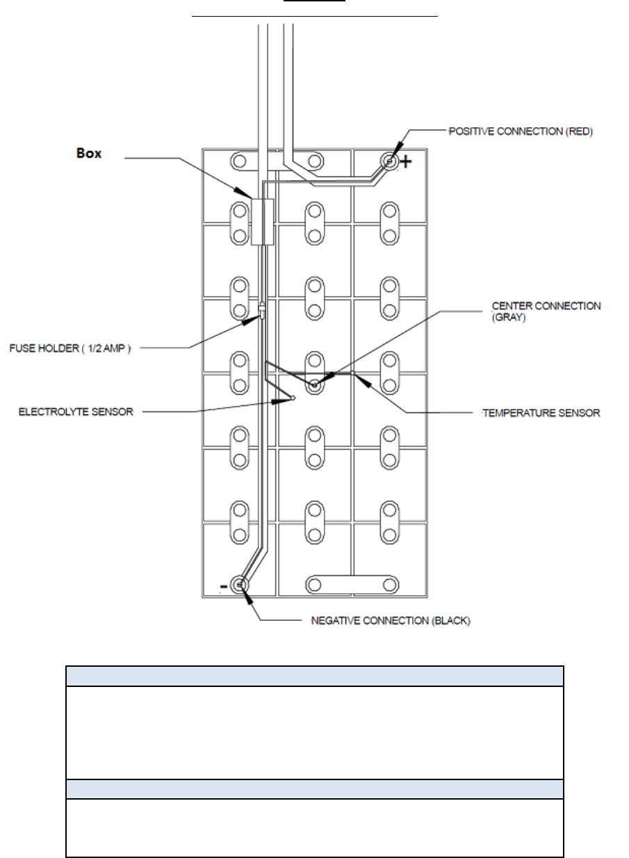
FIGURE 1
EXAMPLE Legacy Box INSTALLATION
FCC Part 15.19 Warning Statement
THIS DEVICE COMPLIES WITH PART 15 OF THE FCC RULES. OPERATION
IS SUBJECT TO THE FOLLOWING TWO CONDITIONS: (1) THIS DEVICE MAY
NOT CAUSE HARMFUL INTERFERENCE, AND (2) THIS DEVICE MUST
ACCEPT ANY INTERFERENCE RECEIVED, INCLUDING INTERFERENCE THAT
MAY CAUSE UNDESIRED OPERATION.
FCC Part 15.21 Warning Statement
NOTE: EnerSys Inc. IS NOT RESPONSIBLE FOR ANY CHANGES OR MODIFICATIONS NOT
EXPRESSLY APPROVED BY THE PARTY RESPONSIBLE FOR COMPLIANCE. SUCH
MODIFICATIONS COULD VOID THE USER’S AUTHORITY TO OPERATE THE EQUIPMENT.