Enforcement Video TRN410 MIC-WRL-TRN-410 User Manual High Fidelity Microphone User Guide
Enforcement Video, LLC (d.b.a. WatchGuard Video) MIC-WRL-TRN-410 High Fidelity Microphone User Guide
User Manual
Document Revision: ReviewDraft_072318_G
Draft

Important Notice
Copyright © 2018 WatchGuard, Inc. All rights reserved. This document
and supporting data are the exclusive property of WatchGuard, Inc. and
may not be copied and/or reproduced without permission.
Software and firmware updates
WatchGuard is committed to the continual testing and improvement of
our software and firmware. As new revisions become available, these
updates will be made available to your agency; fees may apply depending
on your licensing agreement.
Contact information
WatchGuard, Inc.
415 East Exchange Parkway
Allen, Texas 75002
Customer Service: 1-800-605-6734
Customer Service web portal:
https://support.watchguardvideo.com/hc/en-us
Send us your suggestions
Tell us about your experience and how you are using the HiFi
Microphone. We will do our best to accommodate any suggestions you
may have in future revisions.
U.S. customers, call Customer Service or submit a ticket through the
Customer Service web portal. International customers, contact your local
distributor or submit a ticket through the Customer Service web portal.
Trademark notices
All marks, names, and logos mentioned herein are the property of their
respective owners.
ii
WGD00091
Revision ReviewDraft_
072318_G
Draft

FCC and IC notices
This equipment complies with Part 15 of the FCC rules and Industry
Canada licence-exempt RSS standard(s). This equipment should only be
used with the antenna supplied by WatchGuard. Any changes or
modifications not expressly approved by the manufacturer could void the
user's authority to operate the equipment.
Cet appareil est conforme à la Partie 15 des règlements de la FCC et
Industrie Canada exempts de licence standard RSS. Cet appareil doit être
utilisé uniquement avec l'antenne fournie par WatchGuard. Tout
changement ou modification non expressément approuvée par le
fabricant pourrait annuler l'autorité de l'utilisateur de faire fonctionner
l'appareil.
This device complies with Part 15 of the FCC rules and Industry Canada
licence-exempt RSS standard(s) subject to the following two conditions:
1. This device may not cause harmful interference.
2. This device must accept all interference received, including interference
that may cause undesired operation.
Cet appareil est conforme à la Partie 15 des règlements de la FCC et
Industrie Canada exempts de licence standard RSS soumis aux deux
conditions suivantes:
1. Cet appareil ne peut causer des interférences nuisibles.
2. Cet appareil doit accepter toutes les interférences reçues, y compris les
interférences qui peuvent perturber le fonctionnement.
Under Industry Canada regulations, this radio transmitter may only
operate using an antenna of a type and maximum (or lesser) gain
approved for the transmitter by Industry Canada. To reduce potential
radio interference to other users, the antenna type and its gain should be
so chosen that the equivalent isotropically radiated power (e.i.r.p.) is not
more than that necessary for successful communication.
Conformément à la réglementation d'Industrie Canada, cet émetteur radio
ne peut fonctionner à l'aide d'une antenne d'un type et maximum (ou
moins) Gain approuvé pour l'émetteur par Industrie Canada. Pour réduire
le risque d'interférence avec d'autres utilisateurs, le type d'antenne et
son gain doivent être choisis afin que la puissance isotrope rayonnée
équivalente (PIRE) ne dépasse pas ce qui est nécessaire pour une
communication réussie.
The radio transmitter IC:9073A-TRN410 and the base IC:9073A-CHG410
have been approved by Industry Canada to operate with the antenna
types listed below with the maximum permissible gain and required
antenna impedance for each antenna type indicated. Antenna types not
iii
WGD00091
Revision ReviewDraft_
072318_G
Draft

included in this list, having a gain greater than the maximum gain
indicated for that type, are strictly prohibited for use with this device.
lAntenna type (radio transmitter): WatchGuard Video part number
WGP01589 unity gain (0dBi), 50 Ohm impedance
lAntenna type (base): WatchGuard Video part number WGP01573 unity
gain (0 dBi), 50 ohm impedance
Cet émetteur radio IC:9073A-TRN410 et la base IC:9073A-CHG410 ont
été approuvés par Industrie Canada pour fonctionner avec les types
d'antennes énumérés ci-dessous avec le gain maximal admissible et
l'impédance d'antenne requise pour chaque type d'antenne indiqué.
Types d'antennes ne figurent pas dans cette liste, ayant un gain
supérieur au gain maximum indiqué pour ce type, sont strictement
interdites pour une utilisation avec cet appareil.
lType d'antenne (émetteur radio): WatchGuard Video part number
WGP01589 unity gain (0dBi), 50 Ohm impedance
lType d'antenne (base): WatchGuard Video part number WGP01573 unity
gain (0 dBi), 50 Ohm impedance
The antennas used for this transmitter must be installed to provide a
separation distance of at least 20 cm from all persons and must not be
co-located or operating in conjunction with any other antenna or
transmitter.
Les antennes pour cet émetteur doivent être installées en assurant une
distance d'au moins 20 cm de toute personne et ne doivent pas être
situées à proximité ni utilisées en conjonction d'autre antenne ou
émetteur.
This device complies with Health Canada’s Safety Code. The installer of
this device should ensure that RF radiation is not emitted in excess of the
Health Canada’s requirement. Information can be obtained at
http://www.hc-sc.gc.ca/ewh-semt/pubs/radiation/radio_guide-
lignes_direct/index-eng.php
Cet appareil est conforme avec Santé Canada Code de sécurité 6. Le
programme d’installation de cet appareil doit s’assurer que les
rayonnements RF n’est pas émis au-delà de l’exigence de Santé Canada.
Les informations peuvent être obtenues: http://www.hc-
sc.gc.ca/ewh-semt/pubs/radiation/radio_guide-lignes_
direct/index-eng.php
iv
WGD00091
Revision ReviewDraft_
072318_G
Draft

Contents
Contents
Introduction 7
Welcome 8
About this Document 8
Related documents and information 8
About the HiFi Microphone 9
Technical specifications 10
Warranty Information 10
HiFi Microphone 15
Overview 16
Using the HiFi Microphone 17
Beginning a shift 17
During a shift 17
Ending a shift 17
Base 18
Status LEDs 19
DVR cable connection 20
Antenna connection 20
Contacts for charging and synchronizing 21
Transmitter 21
Talk/Mute slide button 22
Display 23
Display backlight button 23
Mode button 23
Status LEDs 24
Power switch 25
WGD00091
Revision ReviewDraft_
072318_G
v
Draft

Contents
Contacts for charging and synchronizing 25
External microphone jack 26
Display 26
Status icons 27
Mode icons 28
Synchronizing the Transmitter and the Base 29
Charging the Transmitter 30
Charging in a vehicle with the ignition off 31
Using Two HiFi Microphones 31
Best Practices and Troubleshooting 33
Best Practices 34
Installation best practices 34
Usage best practices 34
Troubleshooting 35
If you have no reception... 35
If you have poor reception, static, or noise... 35
If the transmitter does not respond to or synchronize with the
base... 36
Index 37
vi
WGD00091
Revision ReviewDraft_
072318_G
Draft


Introduction
Welcome
Welcome to the WatchGuard HiFi Microphone User Guide. This guide is
designed to walk you through the basics of using your HiFi Microphones
(HiFi Mics) to help your WatchGuard 4RE DVRs collect quality audio
evidence.
About this Document
The HiFi Microphone User Guide covers the basic parts of the HiFi Mic as
well as its most common functions including:
lSynchronizing the transmitter (mic) and the base so the DVR can record
audio
lCharging the mic
lTriggering a recorded event from the mic
lPutting the mic into Covert mode
lSetting up the mic to notify you when it has a change to its status
Note: This user guide covers the basic use of the HiFi
Mic. It is not a comprehensive manual for every possible
action or situation you could experience with the HiFi Mic.
If you have a question about the HiFi Mic that is not
covered in the user guide, contact your WatchGuard
representative.
Related documents and information
For subjects related to the WatchGuard 4RE system that are not covered
by the HiFi Microphone User Guide, see the following documents:
l4RE In-Car DVR Quick Start Guide
l4RE In-Car DVR Installation Poster
l4RE In-Car DVR User Guide
8
WGD00091
Revision ReviewDraft_
072318_G
Draft

About the HiFi Microphone
About the HiFi Microphone
The HiFi Microphone (HiFi Mic) is one of the WatchGuard components for
transmitting audio to the 4RE DVR (digital video recorder) during the
video recording process.
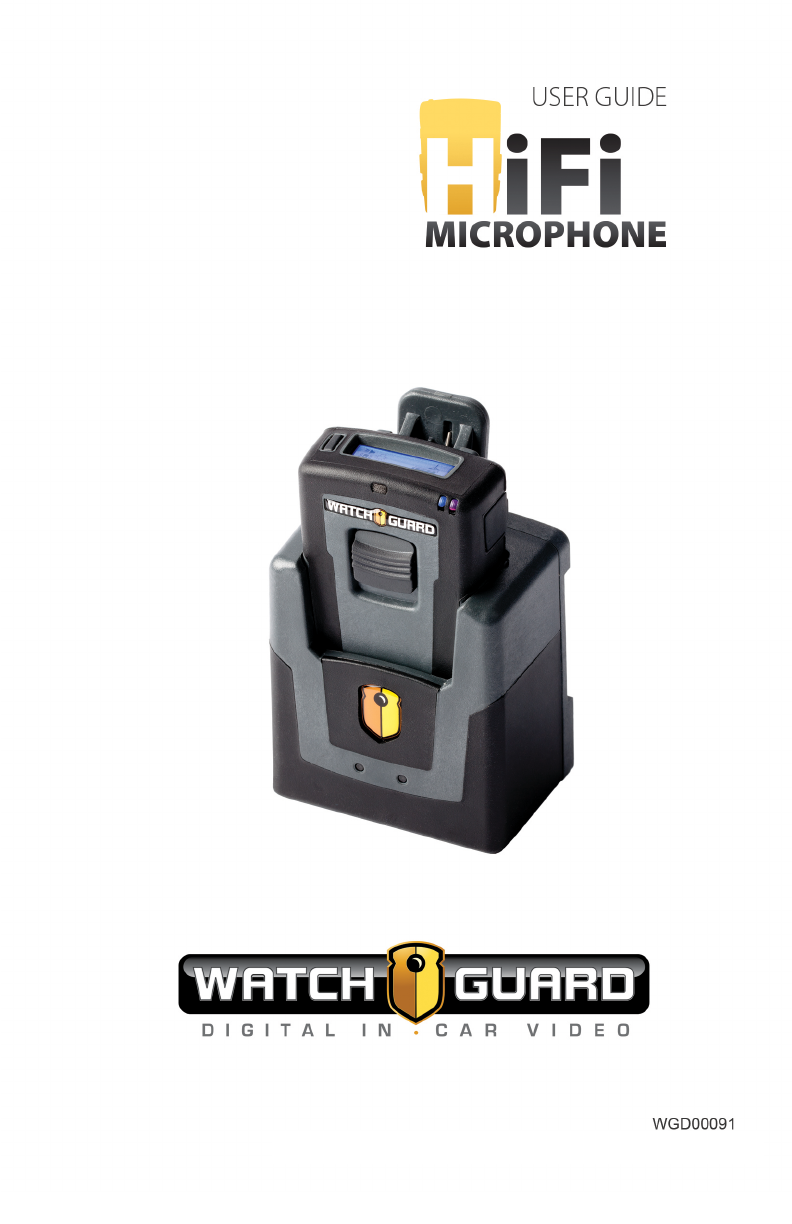
The HiFi Mic consists of two parts:
lBase: The base is the part of the HiFi Mic that is mounted in the vehicle
and physically connects to the DVR and the antenna.
lTransmitter (mic): The mic is the part of the HiFi Mic that you attach to
your apparel or duty belt.
The HiFi Mic performs the following major functions:
lTransmits audio
lSynchronizes the mic and the base so the DVR can record transmitted
audio
lCharges the mic
lTriggers a recorded event
lDisables all mic lights and sounds for Covert mode
lNotifies you when it has a change in its status
WGD00091
Revision ReviewDraft_
072318_G
9
Draft

Introduction
Technical specifications
The following table lists the technical specifications for the HiFi Mic:
Operating
voltage
Transmitter: 4.2 VDC
Base: 12 VDC
Frequency 900 MHz (902 – 928 MHz) – 52 channels, digital spread
spectrum
Operating
range
Over 1 mile in open line of sight
Important! Operating
range differs according to
the environment.
Jacks Transmitter: Lapel microphone jack
Base: 8-pin RJ-45 for power, audio out, and trigger out
Battery Capacity: Lithium-ion 4.2 VDC/1200mAh
Charging time: 3 hours
Stand-by time: 25 days
Talk time: 8-12 hours
Note: Performance can
degrade as the battery ages.
Warranty Information
WatchGuard, Inc., in recognition of its responsibility to provide quality
systems, components, and workmanship, warrants each system, part,
and component it manufactures first sold to an end user to be free from
defects in material and workmanship for a period of one-year from the
date of purchase. A defective component that is repaired or replaced
under this limited warranty will be covered for the remainder of the
original warranty period. Where defects in material or workmanship may
occur, the following warranty terms and conditions apply:
10
WGD00091
Revision ReviewDraft_
072318_G
Draft

Warranty Information
Warrantor
This warranty is granted by WatchGuard, Inc., 415 East Exchange
Parkway, Allen, TX 75002, Telephone: 1-800-605-6734.
Parties to whom warranty is intended
This warranty extends to the original end user of the equipment only and
is not transferable. Any exceptions must be approved in writing from
WatchGuard, Inc..
Parts and components covered
All parts and components and repair labor of the warranted unit
manufactured and/or installed by WatchGuard, Inc. are covered by this
warranty, except those parts and components excluded below.
Parts and components not covered
The limited warranty excludes normal wear-and-tear items such as
frayed or broken cords, broken connectors, scratched or broken displays
or consumable items such as batteries. WatchGuard, Inc. reserves the
right to charge for damages resulting from abuse, improper installation,
or extraordinary environmental damage (including damages caused by
spilled liquids) to the unit during the warranty period at rates normally
charged for repairing such units not covered under the limited warranty.
In cases where potential charges would be incurred due to said
damages, the agency submitting the system for repairs will be notified.
Altered, damaged, or removed serial numbers results in voiding this
limited warranty. If while under the warranty period, it is determined that
the WatchGuard, Inc. system was internally changed, modified, or repair
attempted, the system warranty will become null and void.
Limited liability
WatchGuard, Inc.’s liability is limited to the repair or replacement of
components found to be defective by WatchGuard, Inc. WatchGuard,
Inc. will not be liable for any direct, indirect, consequential, or incidental
damages arising out of the use of or inability to use the system even if the
unit proved to be defective. WatchGuard, Inc. will not be responsible for
any removal or re-installation cost of the unit or for damages caused by
improper installation.
WGD00091
Revision ReviewDraft_
072318_G
11
Draft

Introduction
Remedy
If, within the duration of this warranty, a unit or component covered by
this warranty is returned to WatchGuard, Inc. and proves to be defective
in material or workmanship, WatchGuard, Inc. shall (at its option) repair
or replace any defective components or offer a full refund of the purchase
price. Replacement of a defective component(s) pursuant to this
warranty shall be warranted for the remainder of the warranty period
applicable to the system warranty period.
Shipping
During the first ninety (90) days of the initial warranty period,
WatchGuard, Inc. will provide a prepaid shipping label to return any
defective unit for end users in the continental United States provided
serial numbers are submitted with the request. In such event, contact
WatchGuard, Inc.’s Customer Service Department to request a return
material authorization (RMA) number. Failure to obtain and use a
WatchGuard, Inc. prepaid shipping label in the first ninety days (90) on
the return shipment will result in the end user being responsible for
shipping costs to WatchGuard, Inc. After the first ninety (90) days, the
end user will be responsible for any shipping charges to WatchGuard,
Inc. WatchGuard, Inc. will return ship the product to a customer within
the continental United States by prepaid ground shipping only. Any
expedited shipping costs are the responsibility of the end user.
Customers that are outside the continental United States will be
responsible for all transportation costs both to and from WatchGuard,
Inc.’s factory for warranty service, including without limitation to any
export or import fees, duties, tariffs, or any other related fees that may
be incurred during transportation.
You may also obtain warranty service by contacting your local
WatchGuard, Inc. Authorized Service Center (ASC) for shipping
instructions. A list of local ASCs may be obtained by contacting
WatchGuard, Inc.’s Customer Service Department. Customers will be
responsible for all transportation costs to and from the local ASC for
warranty service.
Extended warranty
Extended warranties may be purchased directly from WatchGuard, Inc.
Any and all extended warranties must be purchased prior to the
expiration of any previous warranty. Failure to purchase an extended
warranty prior to the expiration of the warranty period will require the
covered unit to be physically inspected at the facility of the manufacturer
and any repairs necessary to bring the unit back to full working order
must be performed prior to the issuance of any new warranty. The
12
WGD00091
Revision ReviewDraft_
072318_G
Draft

Warranty Information
customer will be responsible for the cost of the inspection (equal to 1
hour of labor) plus the standard costs associated with any required
repairs. Should you have any further questions regarding the
WatchGuard, Inc. limited warranty, please direct them to:
WatchGuard, Inc.
Attn: Customer Service Department
415 East Exchange Parkway
Allen, Texas 75002
1-800-605-6734
https://support.watchguardvideo.com/hc/en-us
www.watchguardvideo.com
WGD00091
Revision ReviewDraft_
072318_G
13
Draft

14
WGD00091
Revision ReviewDraft_
072318_G
Introduction
This page intentionally left blank.
Draft

HiFi Microphone
HiFi Microphone
In this section...
lHiFi Microphone (HiFi Mic) overview (page 16)
lUsing the HiFi Mic (page 17)
lBase features (page 18)
lTransmitter features (page 21)
lDisplay icons (page 26)
lSynchronizing the base and the transmitter (page 29)
lCharging the transmitter (page 30)
lUsing two HiFi Mics in the same vehicle (page 31)
WGD00091
Revision ReviewDraft_
072318_G
15
Draft
HiFi Microphone
Overview
The WatchGuard HiFi Microphone
(HiFi Mic) consists of two parts:
lBase (page 18)
lTransmitter (mic) (page 21)
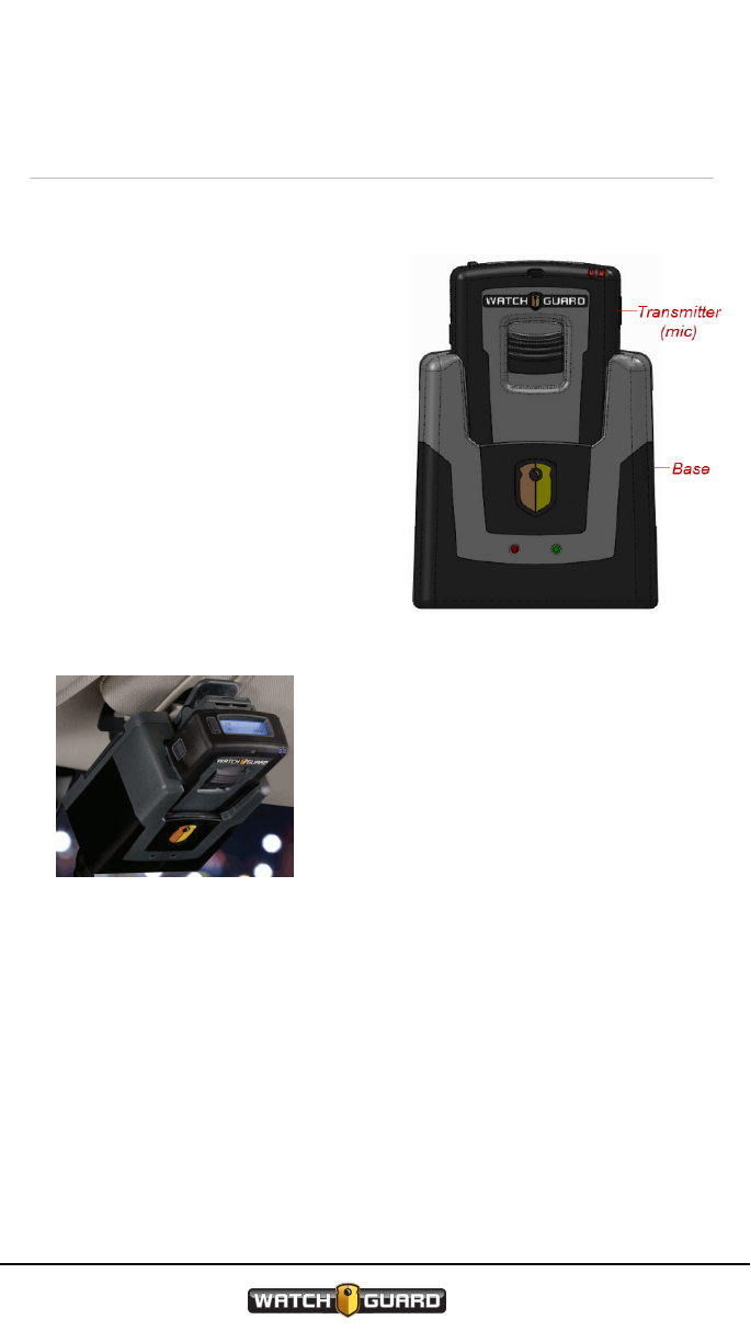
The base is mounted inside the
vehicle and holds the mic when you
are not using it. The mic must be
synchronized with the base in order
for the DVR to record audio. This mic
and base pairing allows the DVR to
detect the mic and its audio
transmission. For information on
syncing the mic with the base, see
Synchronizing the Transmitter and
the Base on page 29.
The base is commonly mounted on
the headliner or center console.
During your shift, you can attach the
mic to your apparel using an alligator
clip or to your duty belt using a
longer belt clip. For information
about these and other accessories,
contact your WatchGuard
representative.
For most agencies, microphones are configured to be inactive (on but not
recording) by default. Triggering a recorded event automatically
activates all microphones. For information on triggering a recorded event
from the HiFi Mic, see Talk/Mute slide button on page 22.
16
WGD00091
Revision ReviewDraft_
072318_G
Draft

Using the HiFi Microphone
Using the HiFi Microphone
You use the HiFi Mic throughout your shift to help your 4RE DVR collect
quality audio evidence.
Beginning a shift
1. Remove the transmitter (mic) from the base and power it on (see Power
switch on page 25).
2. Verify whether the mic is synchronized with the base in your vehicle (see
Status icons on page 27).
3. If needed, sync the mic with the base (see Synchronizing the
Transmitter and the Base on page 29).
During a shift
4. As needed, trigger a recorded event from the transmitter (mic) (see
Talk/Mute slide button on page 22).
5. As needed, mute the transmitted audio from the mic (see Talk/Mute slide
button on page 22).
6. As needed, change the notification mode of the mic (see Mode button on
page 23).
7. As needed, activate the mic's Covert mode (see Mode button on page
23).
Ending a shift
8. Power off the transmitter (mic) (see Power switch on page 25).
Note: WatchGuard recommends that you power
off the mic before you put it in the base to
charge, but this step is not required.
9. Place the mic in the base to charge (see Charging the Transmitter on
page 30).
WGD00091
Revision ReviewDraft_
072318_G
17
Draft

HiFi Microphone
Base
The base is the part of the HiFi Microphone (HiFi Mic) that is mounted in
the vehicle and physically connects to the 4RE DVR and the antenna. The
base:
lSynchronizes with the transmitter (mic) so the DVR can record the audio
the HiFi Mic transmits (see Synchronizing the Transmitter and the Base
on page 29)
lCharges the mic while the mic rests in the base (see Charging the
Transmitter on page 30)
lHolds the mic while you are not using it
Features on the base include:
lStatus LEDs (page 19)
lDVR cable connection (page 20)
lAntenna connection (page 20)
lContacts for charging and syncing with the mic (page 21)
Note: A version of the base exists that only serves as a
charger for the HiFi Mic. This version of the base is not
used in the vehicle. For information about the charge-only
base, contact your WatchGuard representative.
18
WGD00091
Revision ReviewDraft_
072318_G
Draft

Status LEDs
Status LEDs
The HiFi Mic has status LEDs on both the base
and the transmitter (mic). You can use these
LEDs in conjunction with the icons on the
display to determine the status of the HiFi Mic.
On the base, the status LEDs are on the front,
just under the WatchGuard shield symbol.
The LEDs on the base can help indicate the
status of certain functions of the HiFi Mic:
lSynchronizing: As the base syncs
with the mic, both the red and green
LEDs flash. Once the base and mic are
synced, either the green LED turns on
or the red LED starts flashing,
depending on whether the mic is fully charged or begins to charge. For
information about synchronizing the mic with the base, see
Synchronizing the Transmitter and the Base on page 29.
lCharging: The red LED flashes while the mic is charging. When the
mic's battery is fully charged, the red LED turns off and the green LED
turns on. For information about charging the mic in the base, see
Charging the Transmitter on page 30.
lNormal operation: When the base and mic are on and functioning
normally, but not transmitting audio to be recorded, the green LED is on.
lRecording: When the audio transmitted from the mic is being recorded,
the green LED is on. For information about triggering a recorded event
from the HiFi Mic, see Talk/Mute slide button on page 22.
lMuted: When the mic is muted, the green LED flashes. For information
about muting the HiFi Mic, see Talk/Mute slide button on page 22.
lTurned off: When the mic is turned off and not in the base, the red LED
flashes.
lCovert mode: When the mic is in Covert mode, the LEDs on the base
behave normally. Covert mode does not change the LED behavior on the
base. For information on using the HiFi Mic in Covert mode, see Mode
button on page 23.
lLost connection/out of range: If the base loses connection to or is out
of range of the mic, the red LED flashes until the connection is
reestablished.
For information on the status LEDs on the mic, see Status LEDs on page
24; for information on the icons on the display, see Display on page 26.
WGD00091
Revision ReviewDraft_
072318_G
19
Draft
HiFi Microphone
DVR cable connection
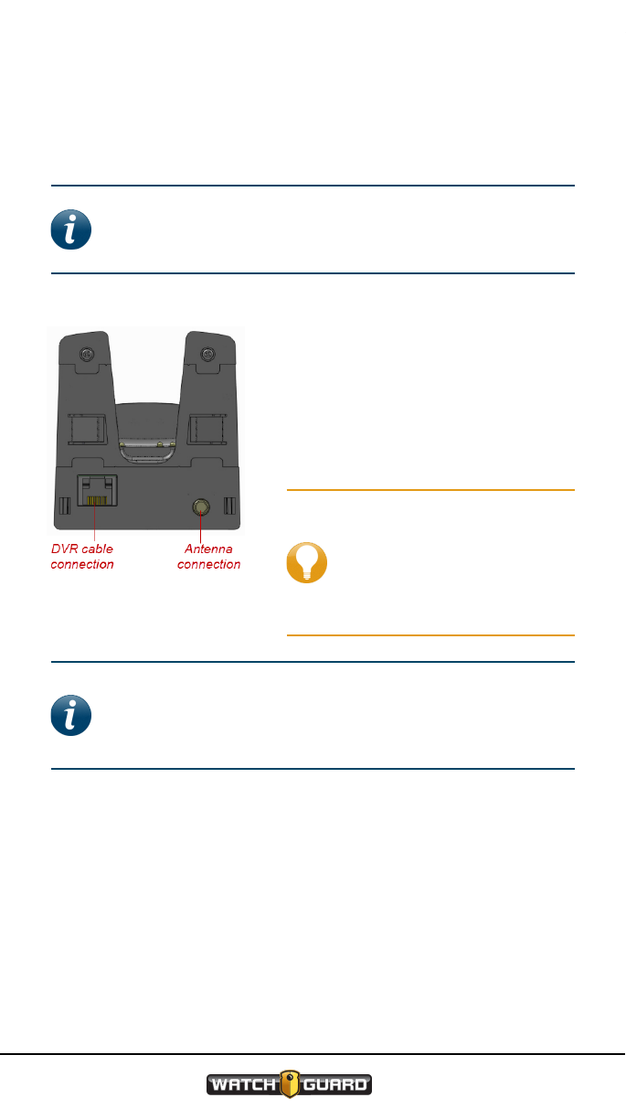
The DVR cable connection is on the back of the base. Connect the DVR
system interface cable to this connection point.
Note: WatchGuard recommends that you use a short
cable (3-foot) to connect the HiFi Mic base to the DVR.
Keeping the cable short helps maintain audio quality.
Antenna connection
The antenna connection is on the
back of the base. Connect the
window-mount antenna to this
connection point.
Tip: Finger-tighten the
SMA connector when you
connect the antenna to
the base. Using hand
tools can damage the
connector.
Note: You should only use the 900 MHz antenna that you
received from WatchGuard with the HiFi Mic. Using a
different antenna can compromise wireless performance
and audio quality.
20
WGD00091
Revision ReviewDraft_
072318_G
Draft
Contacts for charging and synchronizing
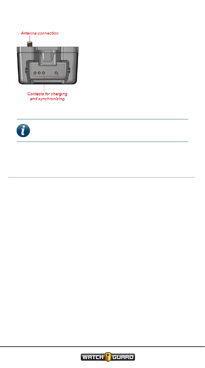
Contacts for charging and
synchronizing
The contacts for charging the
transmitter (mic) and synchronizing
the mic with the base are inside on
the floor of the base. These contacts
physically line up with those on the
bottom of the mic and make it
possible for the base to charge and
sync with the mic.
Note: This graphic shows the base from above, looking
down into it.
Transmitter
The transmitter (mic) is the part of the HiFi Microphone (HiFi Mic) that
you attach to your apparel or duty belt. The mic:
lTransmits audio through the base for the DVR to record
lMutes transmitted audio, as needed (see Talk/Mute slide button on page
22)
lTriggers the DVR to start recording, as needed (see Talk/Mute slide
button on page 22)
lCommunicates its status using the display and the status LEDs (for
information about the icons on the display, see Display on page 26; for
information on the status LEDs, see Status LEDs on page 24)
WGD00091
Revision ReviewDraft_
072318_G
21
Draft
HiFi Microphone
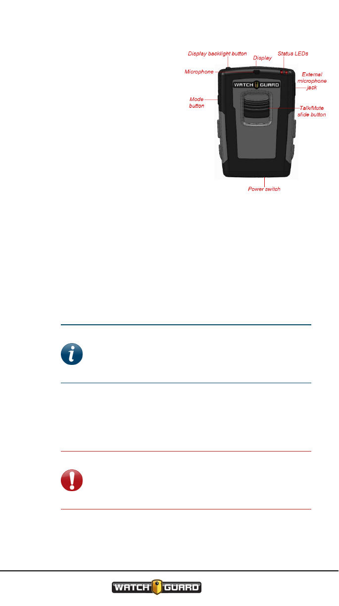
Features on the mic include:
lTalk/Mute slide button
(below)
lDisplay (page 26)
lDisplay Backlight button
(page 23)
lMode button (page 23)
lStatus LEDs (page 24)
lPower switch (page 25)
lExternal microphone jack
(page 26)
Talk/Mute slide button
The Talk/Mute slide button is on the front of the transmitter (mic). Once
you have turned the mic on and synchronized it with the base, the
Talk/Mute button has two functions:
lTriggers the DVR to begin a recorded event
If the DVR is not recording, slide the Talk/Mute button down and
release it to trigger the DVR to begin a recorded event.
Note: If a recorded event is triggered on the
DVR by something other than the HiFi Mic, the
mic audio automatically begins transmitting to
the DVR.
The mic indicates that it is transmitting audio using both an icon on the
display (Record icon) and the status LEDs (green LED is on). For
information on the icons on the display, see Display on page 26; for
information on the status LEDs, see Status LEDs on page 24.
Important! You cannot stop a recorded event
using the HiFi Mic. You can only stop a recording,
even one triggered from the HiFi Mic, using the
DVR display.
22
WGD00091
Revision ReviewDraft_
072318_G
Draft
Display
lMutes the audio being transmitted to the DVR
If the DVR is recording, slide the Talk/Mute button down and hold it to
mute any audio being transmitted to the DVR; no audio is recorded while
you hold the Talk/Mute button down.
The mic indicates that its audio is muted using both an icon on the
display (Mute icon) and the status LEDs (green LED flashes).
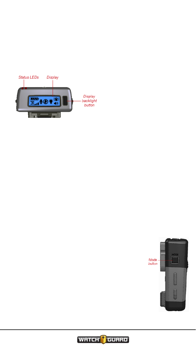
Display
The display is on the top of
the transmitter (mic). The
display shows icons that
indicate the current mic
status (battery, connection,
signal) and mode
(recording/muted, Covert, vibrate/beep/silent). For more information
about the display and its icons, see Display on page 26.
Display backlight button
The Display Backlight button is on the top of the transmitter (mic),
next to the display. When you press this button, the background of the
display lights up, allowing you to see the display icons better, especially
in low-light conditions. When you press the button, the display backlight
turns on for ten seconds.
Mode button
The Mode button is on the left side of the transmitter
(mic), as you look at the front of the mic. The Mode
button has two primary functions:
lChanges the notification mode
The notification mode is one of the ways the mic
lets you know that its status has changed, for
example, the battery is low or it has moved out of
range of the base.
WGD00091
Revision ReviewDraft_
072318_G
23
Draft

HiFi Microphone
You can set the notification mode to any one of four options:
oVibrate and beep
oNo notification
oVibrate only
oBeep only
Press the Mode button twice within two seconds to change the
notification mode. (Pressing it once turns the display backlight on.) As
you continue to press the Mode button within two seconds, the
notification mode cycles through the four options.
The mic indicates which mode is active using an icon on the display
(notification icons). For information on the icons on the display, see
Display on page 26.
lActivates (or deactivates) Covert mode
Covert mode disables the status LEDs and audio notifications on the mic
so no light or sound comes from it without your action. In Covert mode,
the display backlight only lights when you press the Display Backlight
button.
Press and hold the Mode button for two seconds to activate (or
deactivate) Covert mode.
The mic indicates whether it is in Covert mode using an icon on the
display (Covert Mode icon). For information on the icons on the display,
see Display on page 26.
Status LEDs
The HiFi Mic has status LEDs on both the base and the transmitter (mic).
You can use these LEDs in conjunction with the icons on the display to
determine the status of the HiFi Mic.
On the mic, the status LEDs are on the front top-right corner. The LEDs
on the mic help indicate the status of certain functions of the HiFi Mic:
lSynchronizing: As the mic syncs with the base, both the red and green
LEDs flash. Once the mic and base are synced, either the green LED
turns on or the red LED starts flashing, depending on whether the mic is
fully charged or begins to charge. For information about synchronizing
the mic with the base, see Synchronizing the Transmitter and the Base on
page 29.
lCharging: The red LED flashes while the mic is charging. When the
mic's battery is fully charged, the red LED turns off and the green LED
turns on. For information about charging the mic in the base, see
Charging the Transmitter on page 30.
24
WGD00091
Revision ReviewDraft_
072318_G
Draft
Power switch
lNormal operation: When the mic and base are on and functioning
normally, but not transmitting audio to be recorded, both of the LEDs are
off.
lRecording: When the audio transmitted from the mic is being recorded,
the green LED is on. For information about triggering a recorded event
from the HiFi Mic, see Talk/Mute slide button on page 22.
lMuted: When the mic is muted, the green LED flashes. For information
about muting the HiFi Mic, see Talk/Mute slide button on page 22.
lTurned off: When the mic is turned off and not in the base, both of the
LEDs are off.
lCovert mode: When the mic is in Covert mode, both of the LEDs are off.
For information on using the HiFi Mic in Covert mode, see Mode button on
page 23.
lLost connection/out of range: If the mic loses connection to or is out
of range of the base, the red LED flashes until the connection is
reestablished.
For information on the status LEDs on the base, see Status LEDs on page
19; for information on the icons on the display, see Display on page 26.
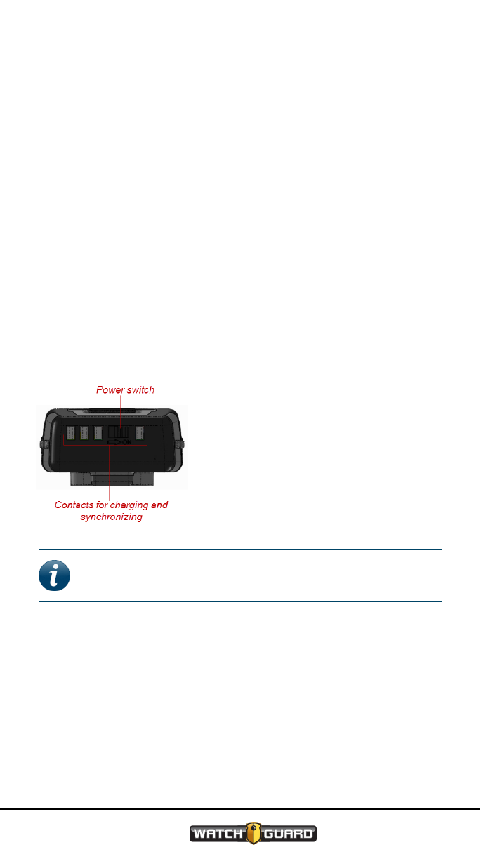
Power switch
The Power switch is on the bottom of
the transmitter (mic) between the
contacts for charging and
synchronizing. Slide this switch to
power the mic on or off.
Note: WatchGuard recommends that you power off the
mic before you put it in the base to charge.
Contacts for charging and synchronizing
The contacts for charging the transmitter (mic) and synchronizing the
mic with the base are on the bottom of the mic. These contacts physically
line up with those inside on the floor of the base and make it possible for
the base to charge and sync with the mic.
WGD00091
Revision ReviewDraft_
072318_G
25
Draft

HiFi Microphone
External microphone jack
The external microphone jack is on the right side of
the transmitter (mic), as you look at the front of the
mic. If you want to use the optional lapel
microphone available from WatchGuard, you can
connect it to the HiFi Mic using the external
microphone jack.
Open the external microphone jack cover and
connect the lapel microphone cable at this point.
Note: The optional lapel microphone can be
less susceptible to wind noise and help provide better
quality audio. For information about the accessory lapel
microphone that WatchGuard offers, contact your
WatchGuard representative.
Display
The display is on the top of the transmitter (mic). The display shows
icons that indicate the current mic status and mode.
Note: This graphic only shows where on the display the
icons can appear. Some of these icons will never appear
on the display at the same time.
26
WGD00091
Revision ReviewDraft_
072318_G
Draft
Status icons
Status icons
The status icons on the display indicate the battery, connection, and
signal states.
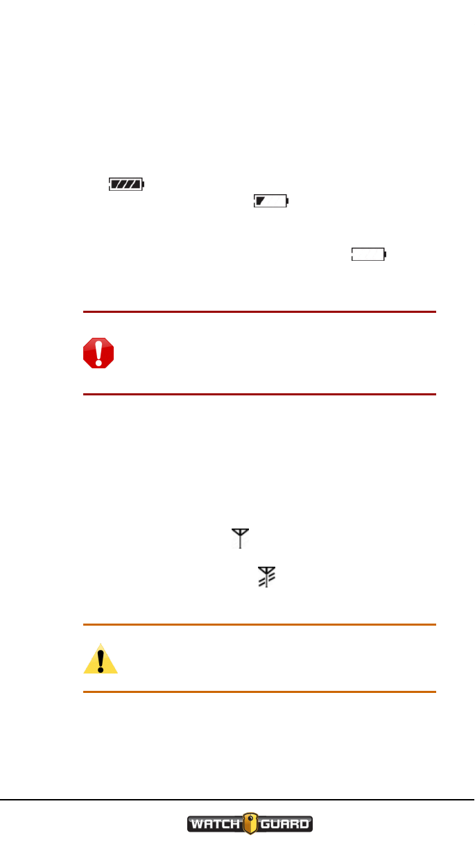
lBattery level: The Battery Level icon is on the top left of the display
and looks like a battery on its side. This icon indicates the charged level of
the transmitter (mic) battery. When the icon shows the battery with all
four bars , the battery is fully charged. When the icon shows less
then four bars, one bar for example , the charge level of the battery
is less than fully charged. (With the battery level icon showing only one
bar, the battery charge is less than 25 percent.)
When the Battery Level icon shows only the outline , the battery
is low; you should place the mic in the base to charge as soon as
possible.
Warning! If the battery outline begins blinking,
the charge level has moved below normal
operational limits; you should place the mic in the
base to charge immediately.
While the mic is charging, the bars in the Battery Level icon cycle on
and off in series.
For information on charging the mic battery, see Charging the
Transmitter on page 30.
lConnection: The Connection icon is on the bottom left of the display,
just under the Battery Level icon, and looks like an antenna. This icon
indicates the state of the connection between the base and the mic. When
the icon shows only the antenna , the mic and the base are synced and
have a fully established connection. When the icon shows the antenna
with blinking diagonal bars across it , the mic and base connection has
weakened.
Caution: When the connection between the mic
and the base weakens, the transmitted audio
quality decreases.
WGD00091
Revision ReviewDraft_
072318_G
27
Draft

HiFi Microphone
When the antenna and diagonal bars blink together, the mic and the base
have lost their connection.
Warning! When the mic and the base lose their
connection, no audio is transmitted to the DVR.
lSignal strength: The Signal Strength icon appears just to the right of
the Connection icon and looks like a set of stair-stepped bars. This icon
indicates the strength of the received signal from the base to the mic.
When the icon shows all four stair-stepped bars , the signal is
strong. When the icon shows less than four bars, two bars for example
, the signal is weaker.
Note: A weaker signal can cause lower quality
audio to be transmitted to the DVR.
Mode icons
The mode icons on the display indicate whether the transmitter (mic)
audio is being recorded, which notification mode is active, and whether
Covert mode has been activated.
lRecord: The Record icon appears in the middle of the display, just to the
right of the Signal Strength icon, and looks like an old-fashioned
microphone . The icon indicates that the transmitted audio is being
recorded by the DVR. For more information, see Talk/Mute slide button on
page 22.
lMute: The Mute icon appears in the middle of the display and looks like a
circled Record icon with a slash through it . The icon indicates that
audio is no longer being recorded by the DVR. For more information, see
Talk/Mute slide button on page 22.
lCovert mode: The Covert Mode icon appears in the middle of the
display, just to the left of the notification icons, and looks like a light bulb.
This icon indicates whether Covert mode has been activated. When the
icon shows a darkened light bulb , Covert mode has been activated.
When the icon shows a lit light bulb , Covert mode has been
deactivated. For more information, see Mode button on page 23.
28
WGD00091
Revision ReviewDraft_
072318_G
Draft

Synchronizing the Transmitter and the Base
lNotification: The notification icons appear in the top and bottom right
corners of the display. There are two notification icons:
oVibrate: The Vibrate icon appears in the top right corner of the
display and looks like a cell phone with squiggly lines on either side
. The icon indicates that the mic vibrates to show a change in its
status.
oBeep: The Beep icon appears in the bottom right corner of the
display and looks like the side view of a speaker with lines coming out
of it . The icon indicates that the mic beeps to show a change in
its status.
Both notification icons can appear together (the mic vibrates and beeps
to indicate a status change), separately, or not at all (there is no
notification of a status change). For more information, see Mode button
on page 23.
Synchronizing the Transmitter and the
Base
The transmitter (mic) and the base in the vehicle must be synchronized
before the DVR can record the audio that the mic transmits. The pairing
that is created when the mic and the base sync with each other lets them
identify each other's communication. (For information on the mic, see
Transmitter on page 21; for information on the base in the vehicle, see
Base on page 18.)
Mics that stay in the same vehicle from shift to shift remain synchronized
with the base in that vehicle. If you move your mic between vehicles or
take it from a pool of mics inside the agency, then you must sync the mic
with the base in the vehicle before you can use it.
Note: A version of the base exists that only serves as a
charger for the HiFi Microphone (HiFi Mic). This version of
the base is not used in the vehicle. For information about
the charge-only base, contact your WatchGuard
representative.
WGD00091
Revision ReviewDraft_
072318_G
29
Draft

HiFi Microphone
The mic and the base in the vehicle sync automatically when you place
the mic in the powered base for a few seconds. To sync the mic with the
base:
1. Power the DVR on and verify it is ready to use.
2. Power the mic on (see Power switch on page 25).
3. Place the mic into the base.
The LEDs on the mic and the base flash and the mic beeps as the pair
syncs.
Note: Once the mic and base are synced, either
the green LEDs turn on (the mic is ready to use)
or the red LEDs start flashing (the mic needs
charging). For information on charging the mic,
see Charging the Transmitter below.
4. Remove the mic from the base and verify their connection on the mic's
display (see Status icons on page 27).
Charging the Transmitter
The battery in the transmitter (mic) must be charged before you can use
the HiFi Microphone (HiFi Mic). The base (either the vehicle base or the
charge-only base) serves as the charger for the mic.
To charge the mic:
1. Power off the mic (see Power switch on page 25).
2. Place the mic in a base.
Note: WatchGuard recommends that you power off the
mic before you put it in the base to charge, but this step
is not required.
If the base is in the vehicle, the base syncs with the mic before the mic
begins to charge. (For more information about syncing the mic and the
base, see Synchronizing the Transmitter and the Base on page 29.) If
the base is a charge-only base, usually used inside your office, the mic
begins charging immediately.
30
WGD00091
Revision ReviewDraft_
072318_G
Draft

Charging in a vehicle with the ignition off
Note: The version of the base that serves only as a
charger for the HiFi Mic is not used in the vehicle. For
information about the charge-only base, contact your
WatchGuard representative.
As the mic charges, the red LEDs flash and the bars in the Battery
Level icon on the display cycle in series. When the mic is fully charged,
the green LEDs turn on and the Battery Level icon shows four bars.
After 30 minutes, the mic is approximately 50 percent charged; the mic
is fully charged after three hours.
Note: If you charge your mic in a charge-only base, you
may need to resync the mic with the base in your vehicle
when you want use it again.
Charging in a vehicle with the ignition off
When you shut down your vehicle, the DVR shuts down with it. Because
the HiFi Mic base is connected to the vehicle through the DVR, the base
shuts down as well.
After ten minutes, the base powers back up and begins to charge the
transmitter (mic). The base remains on for four hours to fully charge the
mic, then the base shuts down.
Using Two HiFi Microphones
For the most part, using two HiFi Microphones (HiFi Mics) in a vehicle is
just like using one. If you use two HiFi Mics in the same vehicle, you need
to implement two items to minimize potential interference:
lWhen you install the HiFi Mic antennas, install them horizontally in the
upper right and upper left corners of the windshield, to keep them as far
apart as possible
lIf you are only using one of the transmitters (mics), dock the unused mic
in its vehicle base
WGD00091
Revision ReviewDraft_
072318_G
31
Draft

32
WGD00091
Revision ReviewDraft_
072318_G
HiFi Microphone
This page intentionally left blank.
Draft


Best Practices and Troubleshooting
Best Practices
The items in the following sections are considered WatchGuard best
practices.
Note: These best practices are meant to help you have
the best experience possible with your HiFi Microphones
(HiFi Mics). They are not required.
Installation best practices
Keep the following best practices in mind when you install a HiFi Mic in
your vehicle:
lUse a short cable (3-foot) when you connect the HiFi Mic base to the DVR;
keeping the cable short helps maintain audio quality
lUse the 900 MHz antenna that you received from WatchGuard with the
HiFi Mic; using a different antenna can compromise wireless performance
and audio quality
lInstall the antenna horizontally in the upper right corner of the
windshield (as you look out the windshield); this placement helps
minimize potential interference
lIf you use two HiFi Mics in your vehicle, install the antennas horizontally
in the upper right and upper left corners of the windshield to keep them
as far apart as possible; these placements help minimize potential
interference
lFinger-tighten the SMA connector when you connect the antenna to the
base; using hand tools can damage the connector
Usage best practices
Keep the following best practices in mind when you use your HiFi Mic:
lPower off the transmitter (mic) before you put it in the base to charge
lIf you have two HiFi Mics in your vehicle, but you are only using one of the
mics, dock the unused mic in its vehicle base; the unused empty base
can interfere with the HiFi Mic that is being used
34
WGD00091
Revision ReviewDraft_
072318_G
Draft

Troubleshooting
Troubleshooting
If your HiFi Microphone (HiFi Mic) is not functioning properly, refer to the
sections below for possible remedies.
If you have no reception...
lCheck that the power switch on the transmitter (mic) is on (see Power
switch on page 25)
lCheck that the mic battery is charged (see Status icons on page 27)
lCheck the connection between the DVR and the base (see DVR cable
connection on page 20)
lCheck that the mic and the base are synced, have a good connection, and
that the mic has a strong signal from the base (see Status icons on page
27)
Tip: If your HiFi Mic still has no reception after trying all
of the above steps, contact WatchGuard Customer
Service for further help.
If you have poor reception, static, or noise...
lCheck the location of the antenna (see Installation best practices on page
34)
lCheck the antenna connection on the base (see Antenna connection on
page 20)
lCheck that the transmitter (mic) and the base are synced, have a good
connection, and that the mic has a strong signal from the base (see
Status icons on page 27)
lIf you have two HiFi Mics in the vehicle, check whether one of them is
unused and NOT docked in its base (see Using Two HiFi Microphones on
page 31)
Tip: If your HiFi Mic still has poor reception, static, or
noise after trying all of the above steps, contact
WatchGuard Customer Service for further help.
WGD00091
Revision ReviewDraft_
072318_G
35
Draft

Best Practices and Troubleshooting
If the transmitter does not respond to or synchronize with
the base...
lCheck that the transmitter (mic) battery is charged (see Status icons on
page 27)
lCheck the connection between the DVR and the base (see DVR cable
connection on page 20)
lCheck that the power switch on the mic is on (see Power switch on page
25), turn it off and back on, then try again to sync the mic and the base
(see Synchronizing the Transmitter and the Base on page 29)
Tip: If your mic still does not respond to or synchronize
with the base after trying all of the above steps, contact
WatchGuard Customer Service for further help.
36
WGD00091
Revision ReviewDraft_
072318_G
Draft

Index
Index
A
activate Covert mode, 24
alert icons, 29
alert mode, 23
antenna
best practices, 34
connecting, 20
icon, 27
B
backlight, 23
bars, signal strength, 28
base
contacts, 21
mounted, 16
overview, 18
status LEDs, 19
synchronizing with
transmitter, 29
Battery Level icon, 27
Beep icon, 29
beep mode, 23
best practices, 34
antenna, 34
DVR connection, 34
installation, 34
bulb icon, 28
buttons
Display Backlight, 23
Mode, 23
Mute, 22-23
Power switch, 25
record, 22
Talk, 22
C
charge level, 27
charging
base LEDs, 19
display icon, 27
transmitter, 30
transmitter LEDs, 24
with ignition off, 31
connecting
antenna, 20
DVR, 20
Connection icon, 27
contacts
base, 21
transmitter, 25
Covert mode
activate, 24
base LEDs, 19
display icon, 28
transmitter LEDs, 25
Covert Mode icon, 28
D
dark bulb icon, 28
deactivate Covert mode, 24
disable lights and sounds,
24
Display Backlight button, 23
display icons, 26-29
alert, 29
Battery Level, 27
Beep, 29
Connection, 27
Covert Mode, 28
Mute, 28
notification, 29
Record, 28
Signal Strength, 28
WGD00091
Revision ReviewDraft_
072318_G
37
Draft

Index
Vibrate, 29
display, overview, 23, 26
dual microphone
configuration, 31
DVR, connecting, 20, 34
E
external mic jack, 26
I
icons
alert, 29
antenna, 27
bars, 28
Battery Level, 27
Beep, 29
Connection, 27
Covert Mode, 28
display, 26-29
microphone, 28
mode, 28
Mute, 28
notification, 29
Record, 28
Signal Strength, 28
status, 27
synchronized, 27
transmitting, 28
Vibrate, 29
ignition off, charging with,
31
J
jack, external mic, 26
K
key the mic, 22
L
lapel mic jack, 26
LCD, 23
LEDs
base, 19
transmitter, 24-25
light, display, 23
lightbulb icon, 28
lost connection
base LEDs, 19
display icon, 27
transmitter LEDs, 25
M
mic
charging, 30
contacts, 25
does not sync with base,
36
overview, 21
status LEDs, 24-25
synchronizing with base,
29
mic jack, 26
microphone icon, 28
Mode button, 23
mode icons, 28
mounted, 16
multiple microphones, 31
Mute button, 22-23
Mute icon, 28
muted
base LEDs, 19
display icon, 28
transmitter LEDs, 25
N
no mic response, 36
no reception, 35
no synchronization, 36
noise, 35
normal usage, 17
base LEDs, 19
transmitter LEDs, 25
notification icons, 29
38
WGD00091
Revision ReviewDraft_
072318_G
Draft

Index
notification mode, 23
O
out of range
base LEDs, 19
display icon, 27
transmitter LEDs, 25
P
pairing, 29-30
poor reception, 35
Power switch, 25
R
recommendations
antenna, 34
DVR connection, 34
installation, 34
record button, 22
Record icon, 28
record stop, 22
recording, 22
base LEDs, 19
display icon, 28
transmitter LEDs, 25
S
Signal Strength icon, 28
slide button, 22
specifications, 10
static, 35
status icons, 27
status LEDs
base, 19
transmitter, 24-25
stopping a recording, 22
synchronized icon, 27
synchronizing
base contacts, 21
base LEDs, 19
display icon, 27
overview, 29
transmitter contacts, 25
transmitter LEDs, 24
T
Talk button, 22
technical specifications, 10
transmitter
charging, 30
contacts, 25
overview, 21
status LEDs, 24-25
synchronizing with base,
29
transmitting
base LEDs, 19
display icon, 28
transmitter LEDs, 25
triggering a recording, 22
turned off
base LEDs, 19
transmitter LEDs, 25
turning on/off, 25
two microphone
configuration, 31
U
using during shift, 17
V
vehicle off, charging with, 31
Vibrate icon, 29
vibrate mode, 23
W
warranty, 10-12
workflow, 17
WGD00091
Revision ReviewDraft_
072318_G
39
Draft

40
WGD00091
Revision ReviewDraft_
072318_G
Index
This page intentionally left blank.
Draft