Engineering 1000R-02 Pocket Remote User Manual
Engineering Industries Pocket Remote Users Manual
Users Manual

E N G I N E E R I N G I N D U S T R I E S Engineering Industries
PO Box 11767
Glendale, AZ 85318-1767
Lighting 1000 Rev. A
Congratulations on your purchase of the inline wireless low-voltage lighting controller system, patent pending. The
system is easy to install and adds a new dimension in customizing your indoor and outdoor low-voltage lighting.
FEATURES
The wireless low-voltage controller system can turn all existing and new low-voltage lighting installations into a zoned
system with wireless control (a zone can consist of one or several controllers). Multiple controllers can be wired on one
transformer. Multiple controllers can be controlled using a single button on your pocket remote. Most dimmers can be
used with this system. Timers can be used and when power is restored the controllers maintain the on/off position prior to
the power interruption (i.e. if the lights were on prior to the timer turning off, the lights will be on when the timer restores
power).
REMOTE OPERATION
Your pocket remote has four buttons you can use to control four separate zones with as many controllers per zone as you
like. The remote buttons correspond to the following zones:
Zone 1 – upper left button
Zone 2 – upper right button
Zone 3 – lower left button
Zone 4 – lower right button
Pressing the button and releasing within two seconds turns the zone on. Pressing the button and holding it down for more
than two seconds turns the zone off. The remote comes from the factory with a battery installed, when replacing, simply
remove the lower portion of your remote to expose the battery (CR2032). Obstructions at the top of the remote, such as
your hand or fingers, will decrease the remote range significantly.
INSTALLATION INSTRUCTIONS
1. Unplug the low-voltage power transformer from the wall outlet.
CAUTION: DO NOT install the controller unit in the high-voltage side (wall plug) of the transformer.
2. Determine the power requirement for your installation. Refer to the Power Requirement section for help
determining the total wattage; do not exceed 150 watts on a single controller unit. Multiple controller units can be
installed for systems requiring more power capacity, see the Installation Example section for more information.
3. Determine where to install the controller unit in your existing/new installation. Realize the remote transmits radio
frequency much like an automatic garage door opener so line-of-sight is not required. Operating range can be as
much as 120 feet however it can vary depending on a number of things, so installing the controller in proximity to
where the lights will need to be controlled will yield the best results. For outdoor applications do not submerge the
controller unit, or locate it in an area where it can come in contact with large amounts of standing water. The
controller can be installed in a variety of ways, use the Installation Example section for possible suggestions.
4. Cut the low voltage wire where you want to install the controller, and strip the insulation off both ends.
5. Connect the power wires (wires connected to the transformer power supply) to the “INPUT” terminals on the
bottom of the controller unit. Most low-voltage lights are alternating current (AC) so it does not matter which wire
goes on the positive side or the negative side. In the very rare case direct current (DC) lights are being
controlled; connect the positive and negative wires according to the markings on the “INPUT” side of the
controller.
NOTE: Be sure not to loosen the two outer mounting screws, connect all wires to the four inner terminals.
6. Connect the load wires (wires with the lights you intend to control) to the “OUTPUT” side of the controller unit.
Again, since most low-voltage lights are alternating current (AC) so it does not matter which wire goes on the
positive side or the negative side. In the very rare case direct current (DC) lights are being controlled; connect the
positive and negative wires according to the markings on the “OUTPUT” side of the controller.
7. Plug the transformer power supply back into the wall receptacle.
All controllers are set at the factory to zone one which will operate using the button located in the upper left of your
remote. If you want to control the lights using a different button (zone) refer to the Zone and Code Settings section. For
best results position controller antenna straight out from the lid.
E N G I N E E R I N G I N D U S T R I E S Engineering Industries
PO Box 11767
Glendale, AZ 85318-1767
Lighting 1000 Rev. A
POWER LIMITATION
The total wattage of all bulbs that are controlled on a single controller cannot exceed 150 watts. For example, 3
floodlights at 20 watts each plus 6 walkway lights at ten watts each would have a total power rating of 120 watts (20 watts
+20 watts +20 watts +10 watts +10 watts +10 watts +10 watts +10 watts +10 watts =120 watts). For lighting systems that
exceed this power requirement, see the Installation Example section for wiring multiple controllers on a single zone.
ZONE AND CODE SETTINGS
Four separate zones are available on each remote.
Controller Zone Setting:
Remove the controller lid by using a Phillips screwdriver to remove the four screws on the controller top; be very
careful not to damage the antenna when removing the lid. The zones are set using the sliding switches located in
the upper left corner. The controller zone is set by moving the slide switch to the right. Only the top four slide
switches are used to set the zone, and only one of the four slide switches can be switched in the “on” position.
For example, if the switch labeled number 2 is in the on position, the controller will respond to zone number 2,
corresponding to button two on the remote (switches 1, 3, and 4 must be in the off position).
The remote and all controllers using a specific remote must be set to the same ID code. Multiple remotes can be used in
the same proximity while controlling different zones if the remotes are set to a unique ID code. You can change your
controllers and remote to a unique ID code if a neighbor has a wireless low-voltage system and it interferes with yours, so
long as the ID code for all of your controllers matches your remote.
Controller and Remote Code Settings:
Setting the ID code in the controller is done much the same way as setting the zone. The ID code is changed
using switches 5-8. Setting the ID code in the remote is done by removing the top of the remote and using the
slide switches 1-4. Switch 1 in the remote corresponds to switch 5 in the controller. For example, turning switch
3 in the remote on, and switch 7 in the controller on will yield the same ID code and the remote will control that
controller.
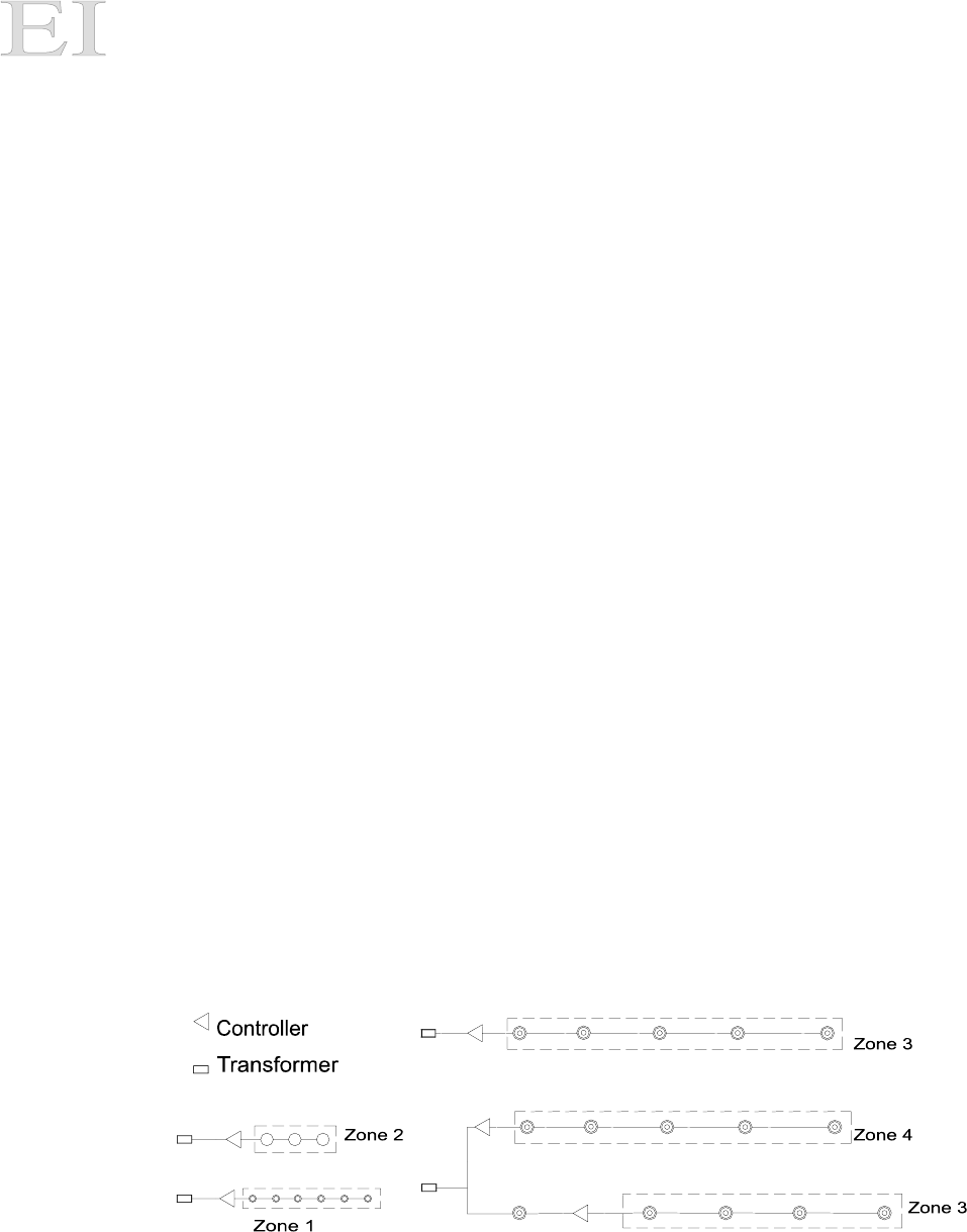
INSTALLATION EXAMPLE
This section contains a diagram of one installation example using multiple controllers and transformers. In this example
zones 1, 2, 3, and 4 are controlled separately. Notice that multiple controllers can be connected to a single transformer
that is over the 150-watt power rating as long as each controller does not control lights that total more than 150 watts. If
you want to control more lights with a single button, simply set multiple controllers to the same zone. Zones 3 and 4 are
on the same transformer but are switches using different remote buttons. This example also shows that separate
transformers can be switched simultaneously by setting controllers to the same zone (zone 3 in this example). One light
connected between the controller and the transformer is not controlled by zone 3. The zones can be located inside and
outside and do not need to be in the same proximity.

E N G I N E E R I N G I N D U S T R I E S Engineering Industries
PO Box 11767
Glendale, AZ 85318-1767
Lighting 1000 Rev. A
RADIO FREQUENCY NOTIFICATION
This equipment has been tested and found to comply with the limits for a Class B digital device, pursuant to Part 15 of the
FCC Rules. These limits are designed to provide reasonable protection against harmful interference in a residential
installation. This equipment generates, uses and can radiate radio frequency energy and if not installed and used in
accordance with the instructions, may cause harmful interference to radio communications. However, there is no
guarantee that interference will not occur in a particular installation. If this equipment does cause harmful interference to
radio or television reception, which can be determined by turning the equipment off and on, the user is encouraged to try
to correct the interference by one or more of the following measures:
• Reorient or relocate the controller antenna.
• Increase the separation between the equipment and the controller.
• Connect the equipment into an outlet on a circuit different from that to which the controller transformer is
connected.
• Consult the dealer or an experienced radio/TV technician for help.
The user is cautioned that changes and modifications made to the equipment without the approval of the manufacturer
could void the user’s authority to operate this equipment.
FCC ID: QRQ1000R-02
This device complies with Part 15 of the FCC Rules.
Operation is subject to the following two conditions:
(1) This device may not cause harmful interference and
(2) This device must accept any interference received, including interference that may cause undesired operation.
Limited Warranty
30-Day Exchange Policy: Engineering Industries (EI) warrants this product against defects in material or workmanship to the original purchaser
for a period of 30 days after the purchase date. To receive a replacement unit, you must present your receipt and
return the original equipment to EI
What’s Not Covered: This warranty only covers defects arising from normal usage and does not cover any malfunction or failure resulting
from misuse, abuse, alteration, modification, or repair. This warranty does not cover controllers subject to power
requirements above the stated rating of 150 watts, nor does it cover controllers subject to standing water conditions.
Additional Limitations: EI shall not be liable for incidental, special or consequential damages resulting from the use of the product or arising
out of any breach of this warranty. All implied warranties, if any, including implied warranties of merchantability and
fitness for a particular purpose, are limited in duration to the duration of this warranty. Some states do not allow the
exclusion or limitation of incidental or consequential damages, or limitations on how long an implied warranty lasts, so
the above exclusions or limitations may not apply to you. No other warranty, written or verbal, will be honored for this
product. This warranty gives you specific legal rights and you may also have other rights that vary from state to state.