Ensight Fluent Transition Assistance From To For Post Processing User Manual En Sight
2017-12-05
User Manual: Ensight Fluent-Ensight-Transition Fluent-EnSight-Transition EnSight10_Docs www3.ensight.com 3:
Open the PDF directly: View PDF ![]() .
.
Page Count: 26
Transition Assistance
from Fluent to EnSight
for Post Processing
Transitioning from Fluent to EnSight for Post
processing
This document highlights the main areas of differences and methodologies which
users should be aware of if they are attempting to transition from Fluent to
EnSight for post processing.
2017
Kevin Colburn
ANSYS, Inc
11/13/2017

Transition Assistance from Fluent to EnSight Page 2
ANSYS, Inc.
2166 N Salem Street, Ste 101
Apex, NC 27523 www.ansys.com
Transition Information
With the introduction of EnSight into the tools available from ANSYS for post processing, the
EnSight team have put together a short “Transition/Orientation Document”. This document’s purpose is
to help users who were used to post processing techniques/methods from Fluent to get oriented to the
techniques, methods, and processes within EnSight for post processing Fluent data. This document
focuses on Fluent-centric operations or environments and the frequently asked questions/main
differences in basic operation within EnSight.
Users are still suggested to utilize the normal EnSight Documentation (Getting Started, HowTo,
User Manual) to learn/understand/utilize EnSight for their post processing needs.
Contents
What’s the best way to bring data from Fluent into EnSight? ................................................................. 3
How do I create Contours in EnSight? ...................................................................................................... 4
Why does my variable distribution look different in Fluent and EnSight? ............................................... 7
Transient Variable Range/Palette ........................................................................................................... 11
Computing Variables in EnSight .............................................................................................................. 12
What’s the EnSight equivalent of Fluent’s Mass Weighted functions? .................................................. 13
Why does the variable value look wrong/missing on the symmetry plane? .......................................... 14
Why does the variable value look wrong on the boundary part? .......................................................... 15
Periodic Streamlines ............................................................................................................................... 16
Rigid Body Motion for Multiple Rotating Reference Frame (MRF) solutions ......................................... 22
Discrete Phase Handling (Particle Tracks) ............................................................................................... 24
Limitations for Fluent to EnSight ............................................................................................................ 25

Transition Assistance from Fluent to EnSight Page 3
ANSYS, Inc.
2166 N Salem Street, Ste 101
Apex, NC 27523 www.ansys.com
What’s the best way to bring data from Fluent into EnSight?
Users have two options to bring the data from Fluent into EnSight: exporting the .dat/.cas format (the
native Fluent format), and loading the dataset with the Fluent reader of EnSight, or exporting the
dataset from Fluent into EnSight Case Gold format and then loading it with the EnSight Case
reader. What's the difference between these two approaches?
Aspect
EnSight Case Format
Fluent Reader (.cas/.dat)
Files
A lot of files and disk space - for each
timestep, there will be one geometry
file (if transient geometry) + one file for
each variable. So, the number of files
grows quickly for transient simulations
Less disk space and files than the EnSight
Case Gold format
Performance
This is the native format of EnSight. The
software is optimized for this format.
Therefore, using this format will result
in less CPU memory and ~ 3X quicker
loading time
The Fluent reader is slower and requires
more memory
Variables on
Boundaries
Fluent does the extrapolation of the
variables onto the boundary parts and
exports them. Therefore, the values are
present on the boundary parts and are
correctly calculated
Fluent doesn't export the values of the
variables onto these parts.
Variables on
Symmetry
Planes
Similar to the point above, Fluent
calculates the value of the variables on
the symmetry plane parts and exports
them into the Case Gold
Fluent doesn't export the values of all
variables onto the symmetry plane parts
Discrete
Phase
Discrete Phase can be exported from
Fluent to Measured Format and
included in the EnSight Case format.
No discrete phase
Computing
Variables
For Volume-based calculations (e.g.
Volume Weighted average), the most
accurate method is to use Elemental
Variables (not Nodal). Specify Elemental
variables on export.
The elemental-only variables available in
the .cas/.dat reader are well suited for
volume based calculations.
Suggestion: Utilize the Fluent export to EnSight Case Format (nodal data) as the most appropriate,
quickest, and most accurate method for getting your data from Fluent to EnSight.

Transition Assistance from Fluent to EnSight Page 4
ANSYS, Inc.
2166 N Salem Street, Ste 101
Apex, NC 27523 www.ansys.com
How do I create Contours in EnSight?
Fluent and EnSight use slightly different terminology, that can trip a user. In this case, Contours is to be
considered a false friend word.
In order to see the distribution of a variable on a 2D part, in Fluent the user creates a Contour. This is a
new part, and is always shown with the distribution of the variable that has been used for its creation.
In EnSight, if the user wants to see the distribution of a variable on a part, s/he will change the "color"
attributes of the part itself to be colored by that variable. This operation will not create a new part, since
the "color by" is considered an attribute of the existing part and not a new part all together. The user
can change the variable s/he is using to color by any time.
EnSight also contains a Contour feature. This is not the same as the Fluent Contour. When the user
creates a Contour in EnSight, this creates a new part that consists on the iso-bar of the variable: 1D lines
that show where the variable has a set value.
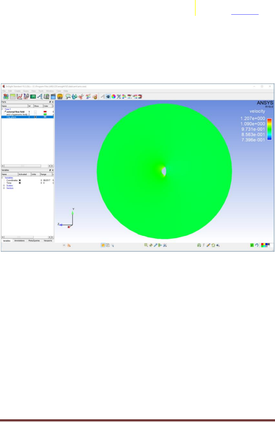
Let's see an example. Launch EnSight and, from the Welcome window, select the AMI Dataset example
session. Select part 1 in the part list, right-click on it -> Clips -> X. This will create a new part with ID = 3,
called Clip_plane. This is a slice in the X direction of the 3D domain.
Now, select this new part in the part list, right-click -> Color by -> Select variable. In the pop up menu
that appears, select the variable pressure (under Scalars). You will see that now the part shows the
distribution of this variable, but no new parts are created in the part list.
Transition Assistance from Fluent to EnSight Page 5
ANSYS, Inc.
2166 N Salem Street, Ste 101
Apex, NC 27523 www.ansys.com
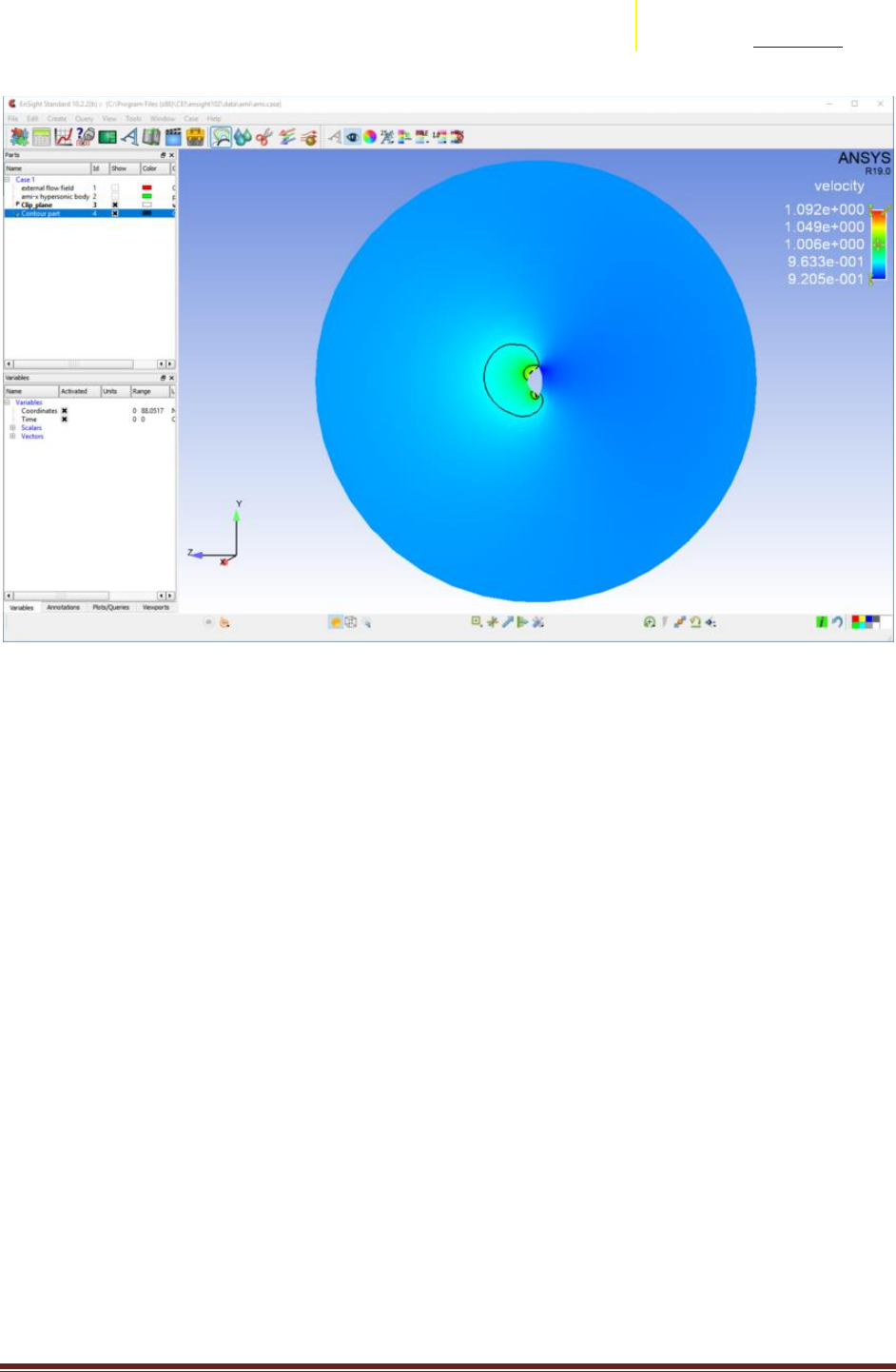
You can right-click again on part 3 and set it this time to be colored by the vector variable velocity. Note
how, also this time, a new part was not created. This is because the color-by is considered an attribute
to a part, not a new part.
The min. and max. of the velocity palette are automatically set to the min. and max. of the variable at
the current timestep on the entire model. Right-click on the velocity legend in the viewport -> Palette ->
Set range to selected viewport min/max. This will change the min. and max. values to create a better
visualization.
Finally, we can create a Contour part and see what this is in EnSight. Right-click on the Clip_plane part in
the part list -> Create -> Contours. In the editor that opens, set as the Variable "velocity", and hit the
"Create with selected parts" button at the bottom of the widget. Note that a new part will appear on the
part list: the Contour part. Right-click on it -> Color by -> Black. Some black lines will appear on the clip.
These lines represent the path along which the velocity has a constant value. If you hide the Clip_plane
part (right-click on it -> Hide), you can see that the Contour part is only these lines.
Transition Assistance from Fluent to EnSight Page 7
ANSYS, Inc.
2166 N Salem Street, Ste 101
Apex, NC 27523 www.ansys.com
Why does my variable distribution look different in Fluent and EnSight?
The visualization of the distribution of a variable in Fluent and EnSight is done using different features:
Contours in Fluent, color-by part attribute in EnSight.
Once you have created the Contour in Fluent and colored the part in EnSight, there will still be some
differences in the visualization. The first clear difference is that the Fluent Contour appears with banded
colors, while in EnSight the colors transition smoother among the elements. It is possible to change the
palette settings in EnSight to get to a more Fluent-like visualization.
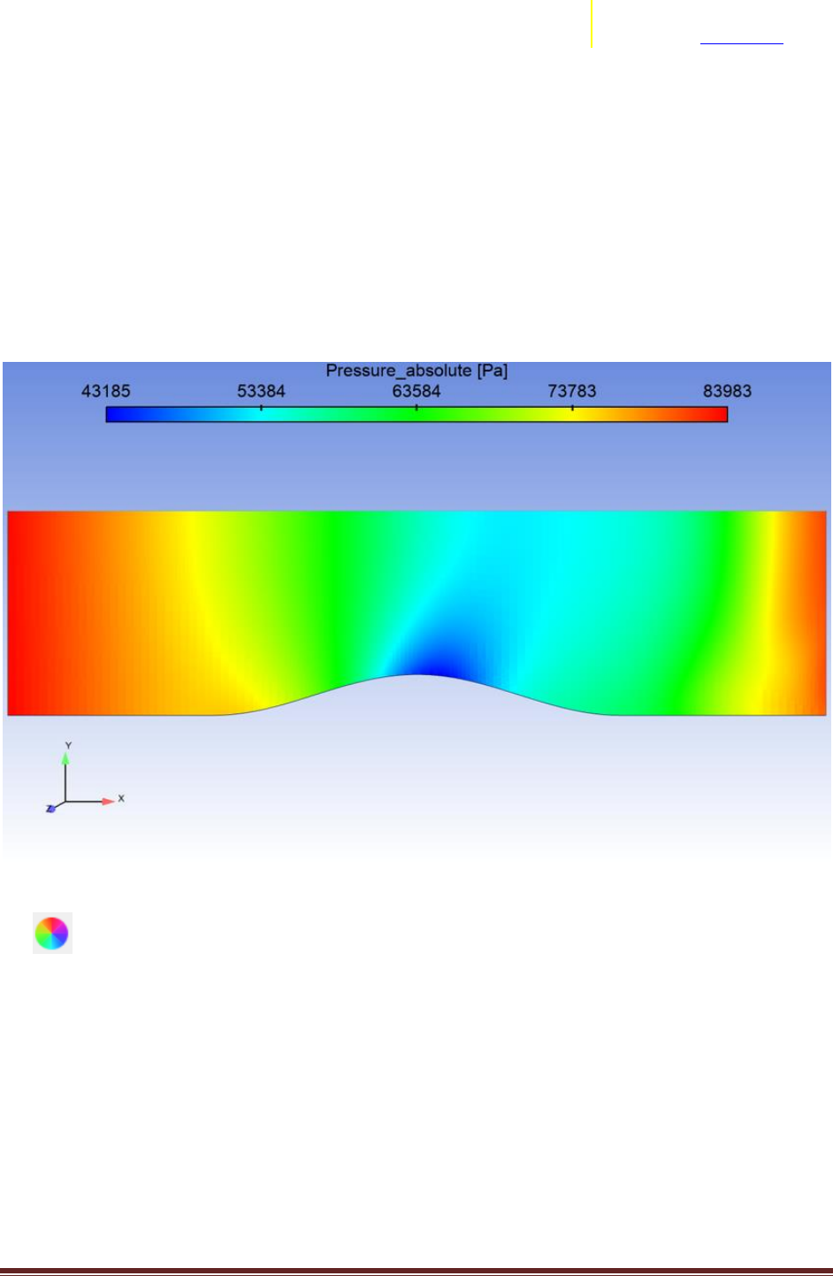
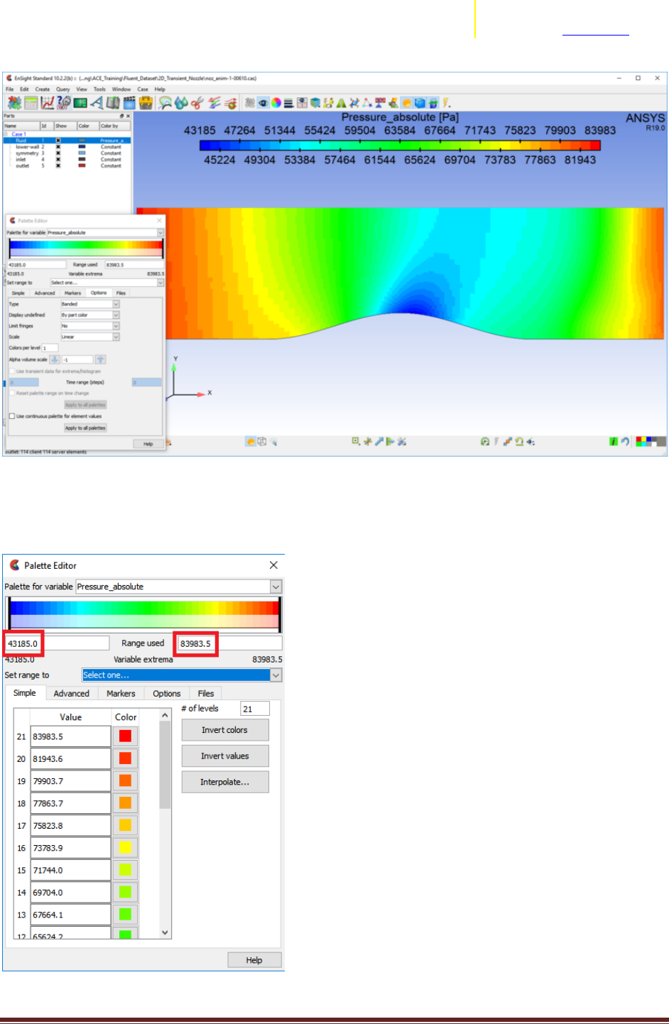
Dataset from the example 2D_Transient_Nozzle, colored by Pressure_Absolute
Select the part you are coloring by the variable, then open the Surface Property Editor by clicking on
the icon in the top toolbar. In the widget that opens, make sure the correct variable is selected,
and then click on the Edit palette.
This opens the palette settings. In the first "Simple" tab, the number of levels is set by default to 5. You
can change this to be 21, which is the number of level of the palette used by Fluent. Then, go in the
Options tab, and set Type to be Banded, and change the number of Colors per level from the default 16
to 0. The color distribution will now be more similar to the Fluent one.
Transition Assistance from Fluent to EnSight Page 8
ANSYS, Inc.
2166 N Salem Street, Ste 101
Apex, NC 27523 www.ansys.com
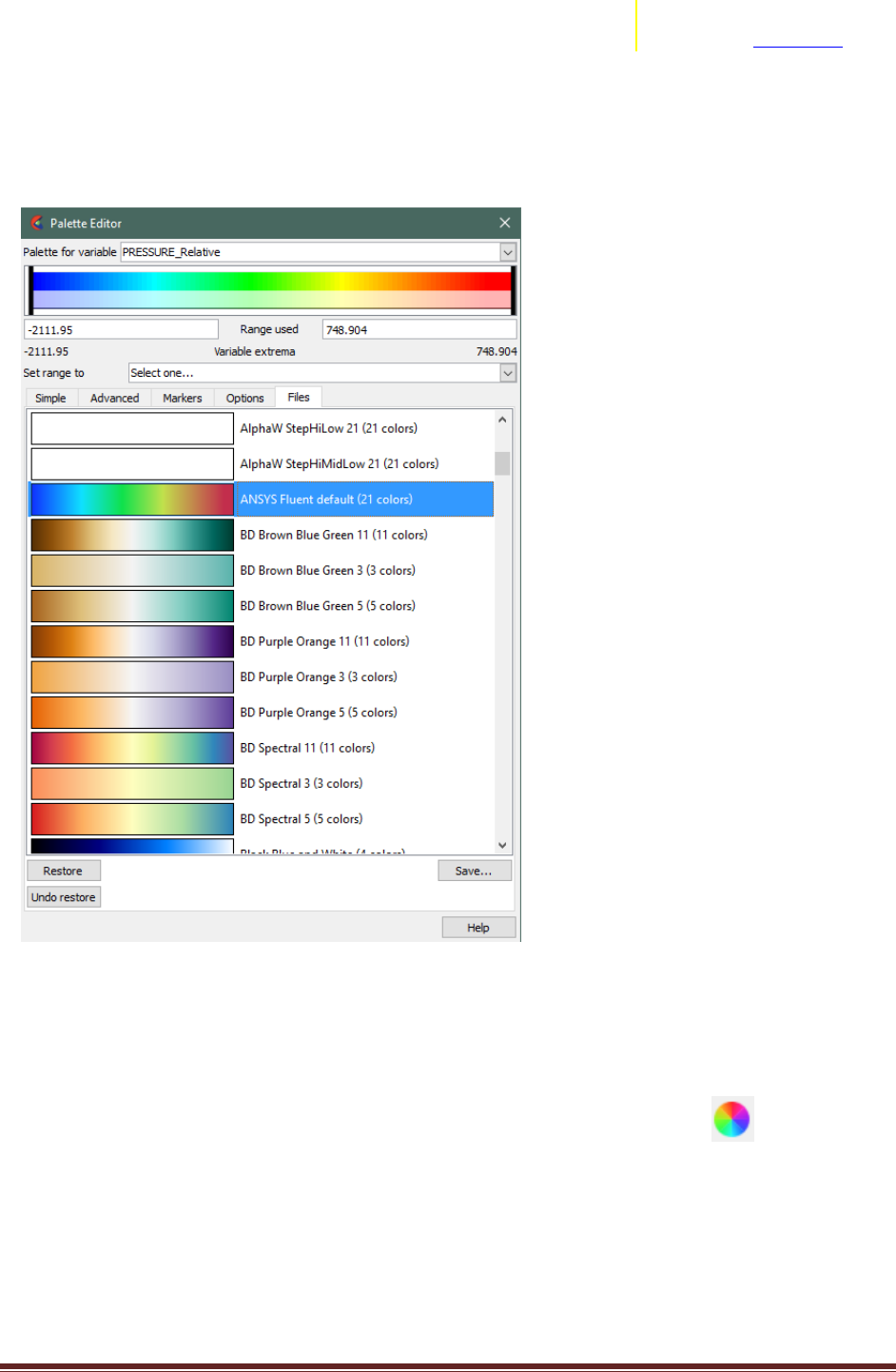
You might still see some difference. Make sure that the min. and max. values of the palette is the same
in Fluent and EnSight. You can change the values in EnSight from the Palette editor, by manually
changing the values in the Range used fields.
Transition Assistance from Fluent to EnSight Page 9
ANSYS, Inc.
2166 N Salem Street, Ste 101
Apex, NC 27523 www.ansys.com
Finally, you can utilize the “ANSYS Fluent Default” Color Palette for the palette coloration. To invoke this
palette, open the Palette Editor (as shown above), and select on the “Files” tab. You can then choose
from the color palette files to apply for this particular variable. In the alphabetical list, you can choose
the “ANSYS Fluent Default” palette, and select “Restore” at the bottom of the dialog.
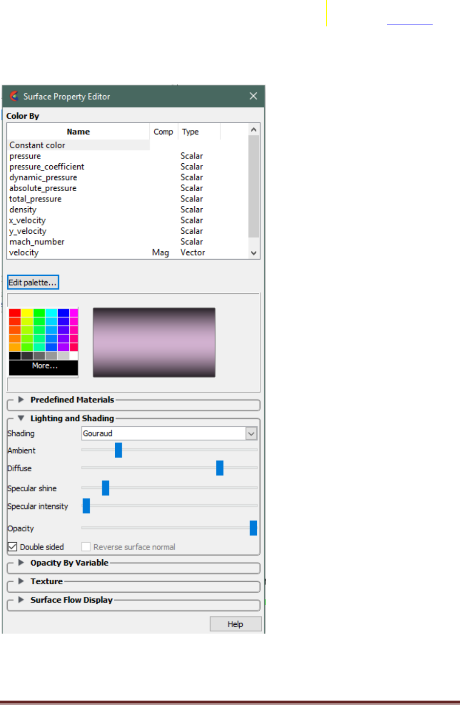
Lighting options. The light diffusivity setting for EnSight may be different, causing shading changes
effecting different parts of the color palette differently. You can inspect/change the lighting settings by
first selecting the part(s) you’d like to change, then selecting the Surface Color icon and adjust the
“Diffuse” setting. We’ve found that a setting of approximately 85% tends to match the diffusivity in
Transition Assistance from Fluent to EnSight Page 11
ANSYS, Inc.
2166 N Salem Street, Ste 101
Apex, NC 27523 www.ansys.com
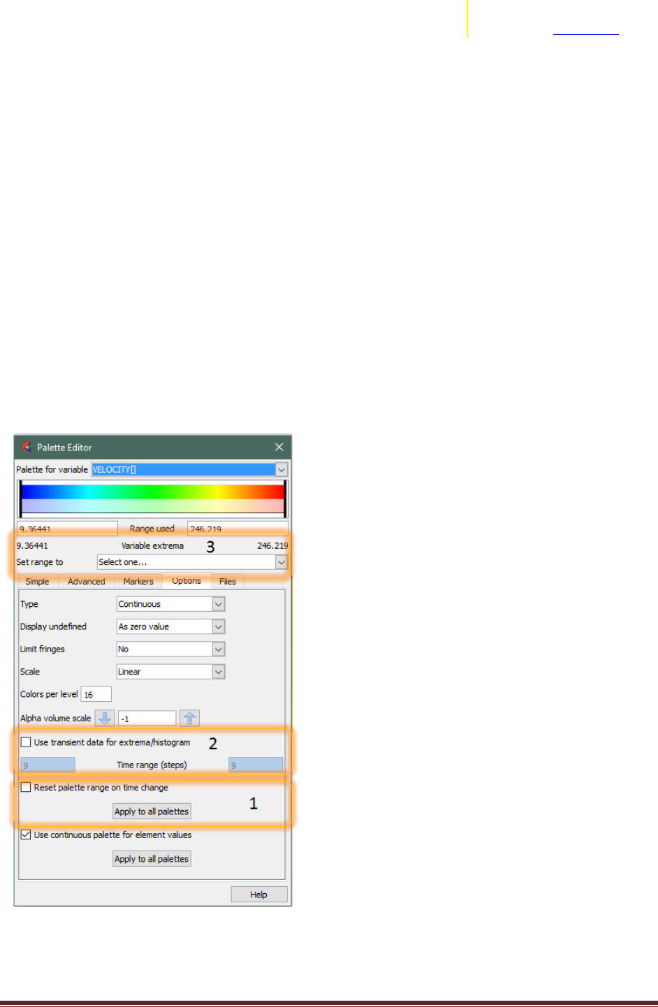
Transient Variable Range/Palette
EnSight’s default operation with Transient models and variables may be different to your Fluent
operation. With Transient models in EnSight, when the user first activates a variable (either through
coloration or part creation based on it), EnSight takes the variable’s extrema at that timestep to
determine the current range of the palette used for that variable. If the user changes timesteps, the
range is not automatically changed (by default), and therefore the coloration stays consistent between
timestep changes, but the range in the palette may not reflect the current range of the variable in the
model.
There are a few options in EnSight to cater to the changes in variable range over time.
Option 1: Automatically adjust the palette on timestep change (each timestep the min/max of the
palette is changed to match the current timestep’s min/max). Simply toggle on the “Reset palette range
on time change” option in the Palette Editor.
Option 2: You can turn on the “Use Transient data for extrema/histogram” to instruct EnSight to use the
temporal min/max to determine the “Set Range to..” in location (3) in the image below.

Transition Assistance from Fluent to EnSight Page 12
ANSYS, Inc.
2166 N Salem Street, Ste 101
Apex, NC 27523 www.ansys.com
Computing Variables in EnSight
EnSight has a fully featured calculator to determine new spatial, temporal derived variables
from a relatively wide set of both PreDefined functions (e.g. Spatial Mean, or Flow Rates) or user
defined equations (e.g. Cp = Pressure / Pdyn). In addition, you can calculate can derived quantities from
the solution based on either nodal or elemental based variables (variables defined at nodes/vertices or
elements/cells). Data read in through the Fluent .cas/.dat file reader into EnSight is elemental based,
while data exported from Fluent to the EnSight Case format can be either nodal or elemental. EnSight
can also convert from nodal to/from elemental data using a very basic straight averaging routine. As
Fluent’s solver is elemental based, if you desire to calculate elemental based variables (e.g. Volume
Weighted Average Temperature) as close to that reported by Fluent, you should utilize elemental
variables exported from Fluent, or directly through the .cas/.dat reader. The differences in variable
calculation between nodal and elemental variables differ only in regions which suffer from high
gradients relative to the discretization used.

Transition Assistance from Fluent to EnSight Page 13
ANSYS, Inc.
2166 N Salem Street, Ste 101
Apex, NC 27523 www.ansys.com
What’s the EnSight equivalent of Fluent’s Mass Weighted functions?
The Calculator feature of EnSight contains a few predefined variables that can be used to calculate mass
weighted averages.
The first function is SpaMeanWeighted(). This function takes as input two variables, and returns the
sum of variable1 * variable2 * the size of the elements divided by the sum of variable2 * the size of the
elements. So, it returns the average of variable1 weighted by variable2. If you set variable2 to be the
density, this is the same as the mass-weighted average. Note that this function works both on 2D and
3D elements (the only difference being, you'll need to use surface or volumetric density).
Fluent contains two functions that calculate Mass-Weighted Averages. From the Fluent documentation:
1. Surface Integral of Mass-Weighted Average
The mass-weighted average of a quantity is computed by dividing the summation of the value of the
selected field variable multiplied by the absolute value of the dot product of the facet area and
momentum vectors by the summation of the absolute value of the dot product of the facet area and
momentum vectors (surface mass flux)
EnSight's calculator function MassFluxAvg is the equivalent of this Fluent function. Note how this
definition includes velocity and Normal vector fields (which isn't the case for the next function).
2. Volume Integral of Mass-Weighted Average
The mass-weighted average of a quantity is computed by dividing the summation of the product of
density, cell volume, and the selected field variable by the summation of the product of density and cell
volume
EnSight's SpaMeanWeighted() function with volumetric density as the second variable is equivalent to
this function.
EnSight has a comprehensive Calculator to perform not only new spatial (e.g. Pressure / 0.5 *
rho * velocity2) or temporal variables (e.g. TemporalMean), the calculator can be used to calculate items
like Flow rate (Flow() function), Line/Surface/Volume integrals, boundary layer calculations, min
distance calculations, element metrics, and many more. Please reference the EnSight User Manual
Chapter on Calculator to obtain a broader picture of the capabilities within EnSight to derive analytical
quantities from the domain and variables.

Transition Assistance from Fluent to EnSight Page 14
ANSYS, Inc.
2166 N Salem Street, Ste 101
Apex, NC 27523 www.ansys.com
Why does the variable value look wrong/missing on the symmetry plane?
Note: This note is written as of EnSight version 10.2.2(b).
In Fluent, the user can visualize the values of variables on these symmetry planes. When the user then
brings the data into EnSight, some variables appear to be undefined on these symmetry planes.
Why does this happen?
The post processor contained in Fluent has information about the physics of the simulation, and how
this physics is implemented in the solver. It knows that this is a symmetry part, and therefore when the
user asks to visualize a variable on it, it knows how to take the values from the fluid domain and extract
them correctly onto the symmetry plane part. On the other hand, EnSight has no knowledge about the
settings of the simulation. For some variables, the data files that Fluent exports do not contain their
values on the part that corresponds to the symmetry plane, and EnSight doesn't know that this is a
symmetry plane, and it doesn't know how to correctly extract the values from the fluid domain onto this
part. Therefore, it leaves these variables as undefined.
Is there a work-around?
If you are reading Exported data from Fluent to EnSight Case format: YES. If you utilize the Fluent
export to EnSight format, you will receive variable values on boundaries like symmetry planes.
If you are reading Fluent .cas/.dat files : Unfortunately, there isn't any work around. The data simply
isn't contained in the files EnSight has access to, and EnSight cannot do the physical interpolations
needed to derive these values. One possibility is to use the calculator CaseMap function to map onto the
symmetry plane the value of the variables just inside the fluid. Note that this isn't an extrapolation, but
simply a copy-paste of the values from the fluid onto the symmetry part, so it will still show a slight
difference compared to the results in Fluent. A modification to the fluent reader is planned to attempt
to address this issue of missing/non existent variable values on certain boundaries (symmetry planes
being one of them).

Transition Assistance from Fluent to EnSight Page 15
ANSYS, Inc.
2166 N Salem Street, Ste 101
Apex, NC 27523 www.ansys.com
Why does the variable value look wrong on the boundary part?
As a part of the simulation set up in Fluent, the user can set some parts to be Boundaries, fixing
the value of a variable on them. When doing so, if the user creates a Contour for the Boundary part in
Fluent with this variable, s/he knows exactly what values will be visualized.
If now the user brings the data into EnSight and colors the Boundary part by the variable, it's possible
that the user will not see the expected value.
What is going on?
Fluent stores the information about the variable values at the elements centroid, usually. On a Boundary
part, though, the value that is imposed by the user is stored at the nodes. The element centroid will
contain a value that is the interpolation between the faces on the Boundary part and the neighboring
fluid elements - so, a value that will not correspond with what the user has set as Boundary condition.
When the user asks Fluent for a contour of the Boundary part, Fluent knows that this is a Boundary and
therefore, instead of showing the value of the variable at the element centroid, as it would usually do, it
shows the values at the nodes.
EnSight doesn't have access to the same level of knowledge. When the user asks to visualize a variable
on a part, EnSight doesn't know if the part is a Boundary part or not, and will simply show what the data
file contains. So, if the data file contains the variable stored at the elements centroid, this is what is
going to be visualized - which will look "wrong" to the user, and not consistent with what Fluent
displays.
The user can verify that, indeed, the data is the same in the two software by toggling off the "Node
values" in Fluent (which will force it to display the elemental values), or by using the Fluent console to
extract the values at the Boundary.
Transition Assistance from Fluent to EnSight Page 16
ANSYS, Inc.
2166 N Salem Street, Ste 101
Apex, NC 27523 www.ansys.com
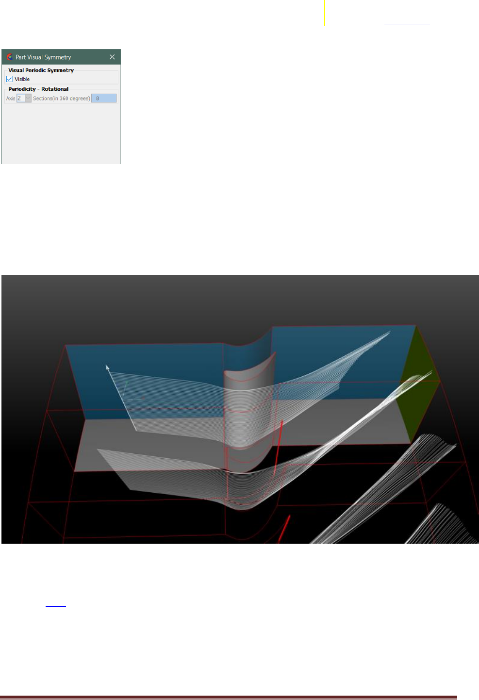
Periodic Streamlines
Introduction:
New in EnSight 10.2, is the ability to generate "Periodic Streamlines". This allows models which were
solved using Periodic Boundaries (sometimes referred to as Cyclic Boundaries) to create streamlines
which re-enter the domain when the streamline exits through one of the periodic face. The re-enter
point is the corresponding location on the matching periodic face. This can be quite helpful in visualizing
a complete streamline, rather than the streamline stopping when it has reached the physical extent of
the domain (rather than the computational extent of the domain). This capability exists for both
Streamlines (steady state) and Pathlines (transient).
Procedure:
There are two basic items which need to be setup for calculating Periodic Streamlines. (1) The parent of
the streamline (typically the fluid part(s)) must have their periodicity setup within the "Visual Symmetry"
dialog box. (2) When creating the streamline, you must have the "Compute Using Periodicity" option
turned ON.
Step 1:
The Parent of the streamline (typically the fluid part(s)) must have their periodicity setup. For each
parent part, the Visual Symmetry Dialog must be setup for the appropriate rotational periodicity.
The Axis of Periodicity must be set.
The Number of sections in a full 360 degrees must be set.
Transition Assistance from Fluent to EnSight Page 17
ANSYS, Inc.
2166 N Salem Street, Ste 101
Apex, NC 27523 www.ansys.com
Step 2:
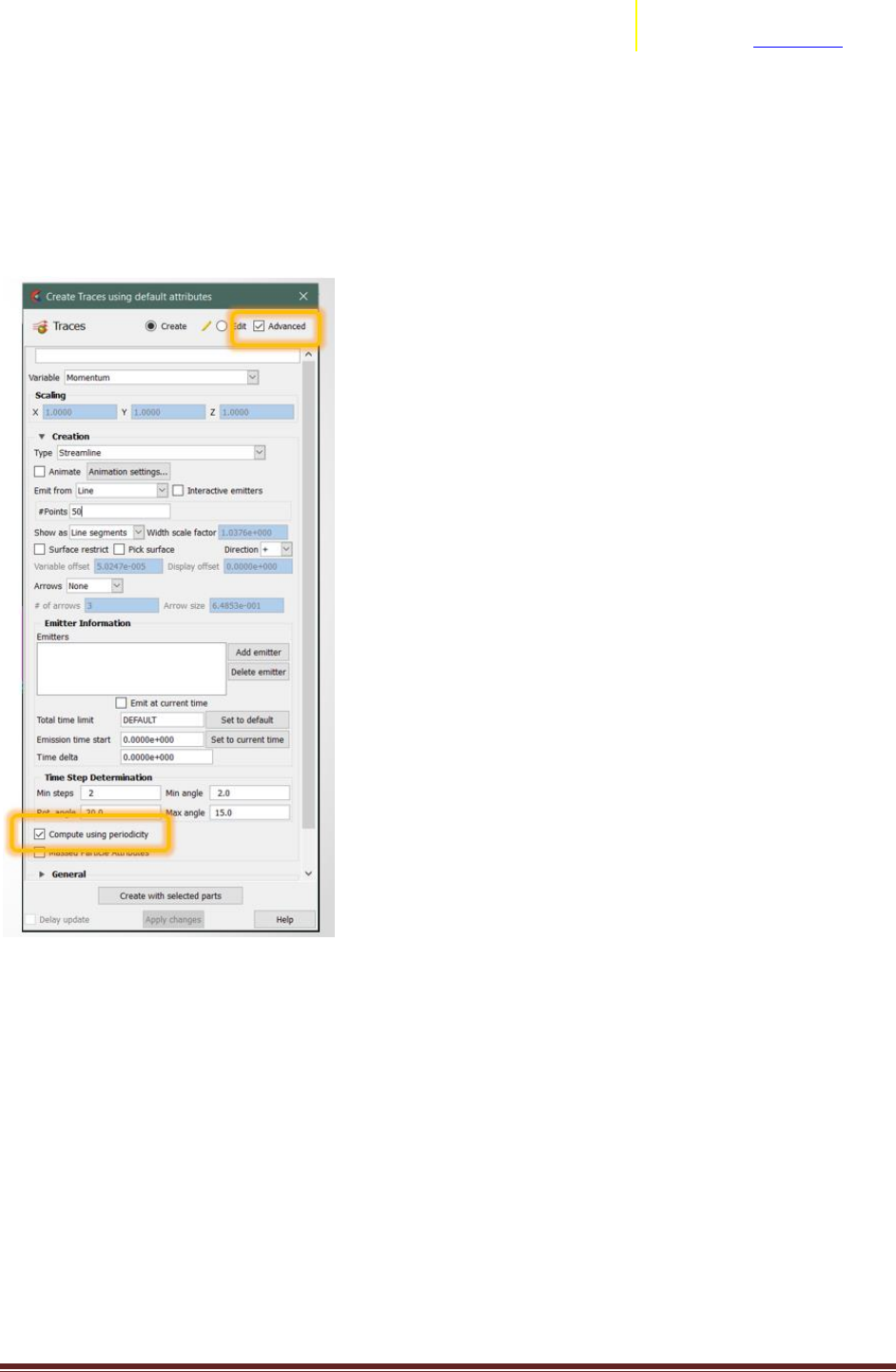
The creation of the streamline must have the "Compute using Periodicity" toggle enabled. This toggle
can be found in the "Advanced" section of the Create Traces Dialog:
Notes:
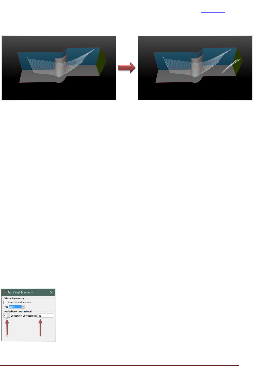
1. Most solvers apply this periodicity as a face boundary condition. However, in EnSight, the
specification of periodicity is done to the fluid domain, and NOT to the periodic face. In the example
below, both the orange and blue parts need to be specified as periodic for streamlines to correctly pass
through. If you fail to specify the blue part as periodic, the streamlines can appear to stop at the
interface.
Transition Assistance from Fluent to EnSight Page 18
ANSYS, Inc.
2166 N Salem Street, Ste 101
Apex, NC 27523 www.ansys.com
2. As the streamline exits the physical domain of the parents, the parents are checked for their
"periodicity", and if on, EnSight then looks at the periodic copy for existence of a domain and continues
to integrate the streamline. The visual presentation of the periodic streamline remains within the
physical boundaries of the parent part.
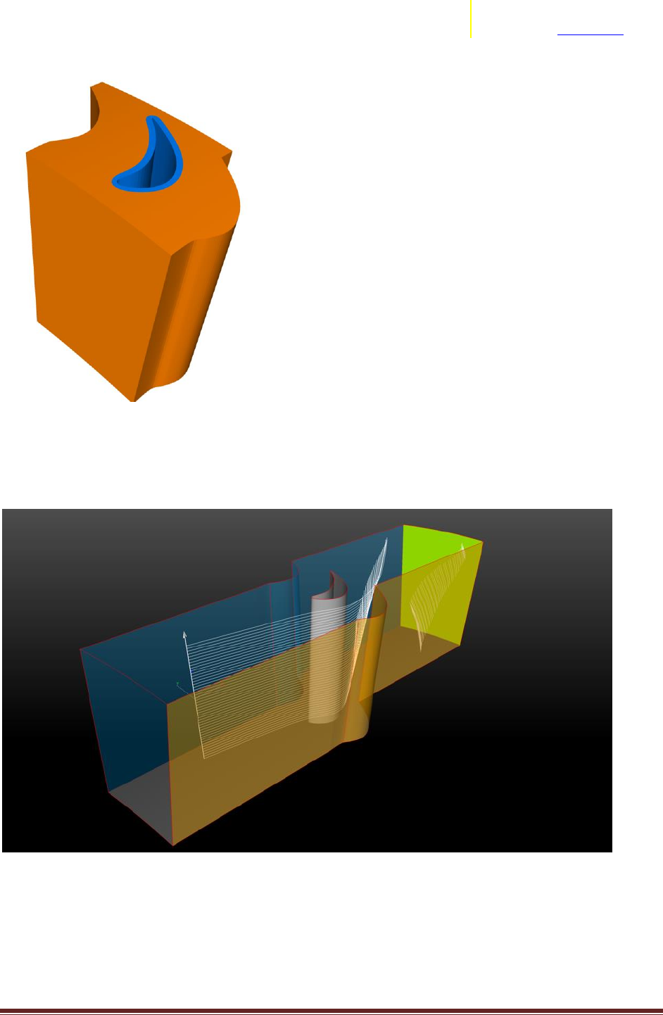
3. Passages can have different periodic (angular) extents. Each different periodic (angular) extent should
be a different part, so that you can specify the appropriate periodicity sector count for each angular
extent. In the example below, there are at least 3 fluid parts, allowing 3 different angular repeat sectors.
Transition Assistance from Fluent to EnSight Page 19
ANSYS, Inc.
2166 N Salem Street, Ste 101
Apex, NC 27523 www.ansys.com
You can see that this single rake of streamlines can be correctly computed through the different angular
passages, which in this case, results in what appears to be many streamlines in the downstream portion
(due to high swirl).
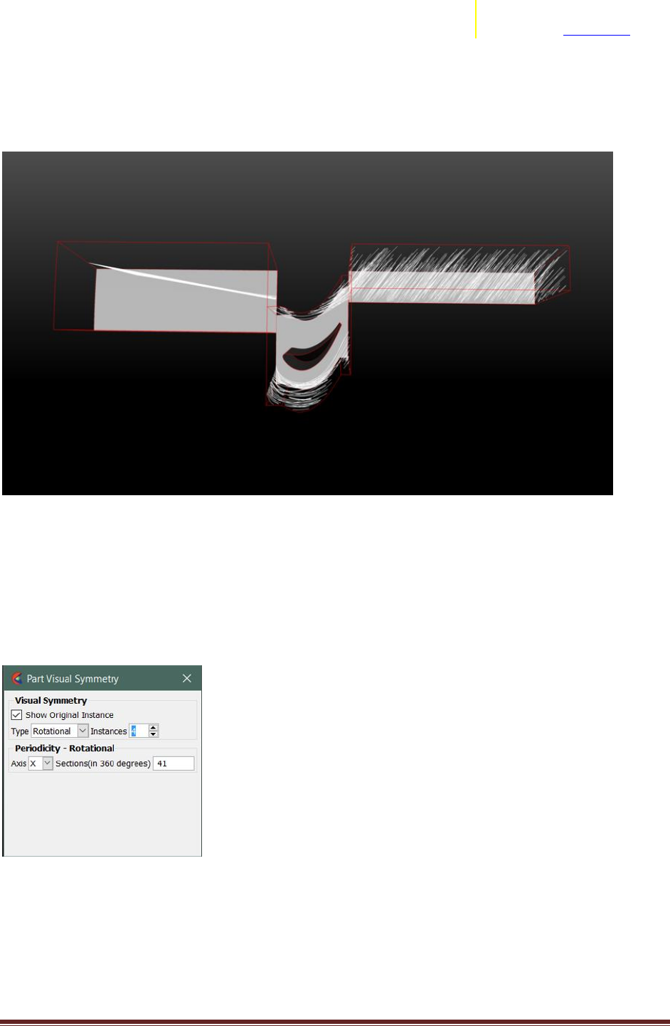
4. To visualize more than the one passage of streamlines, you must do the following two steps: (1) Fluid
Parent: Turn on the Rotational Symmetry and Instances in the Part Visual Symmetry Dialog, (2)
Streamline Part: Toggle on the "Visible" in the Part Visual Symmetry Dialog.
For the Fluid Parents, the dialog would look like:
For the Streamline Part, the dialog would look like:
Transition Assistance from Fluent to EnSight Page 20
ANSYS, Inc.
2166 N Salem Street, Ste 101
Apex, NC 27523 www.ansys.com
The reason why you only have a visible toggle in the Streamline's Part Visual Symmetry Dialog is that the
streamline may pass through different angular extents, requiring differing amounts of rotational offset
along its path. Therefore, it does not make sense to have a single angular setting for the streamline.
Instead, EnSight determines the angular setting based on which parent it currently is contained.
In the end, you can visualize a continuous streamline from inlet to outlet by visualizing more than a
single instance:
For a generic example to try yourself, please find below a link to an EnSight session file containing an
example dataset.
Download here
You have a single .ens file. Simply load this into EnSight. For setup, you will need to know that the
periodicity angular sector count is 41 (there are 41 sections in 360 degrees) about the X-axis. You should
be able to follow the above instructions to try out periodic streamlines.

Transition Assistance from Fluent to EnSight Page 21
ANSYS, Inc.
2166 N Salem Street, Ste 101
Apex, NC 27523 www.ansys.com
Caveats:
As of 22-Jan, the following caveats exist:
A. Does not work with Massed Traces
B. Does not work with Surface Restricted Traces.
C. Only works in Rotationally Periodic models.

Transition Assistance from Fluent to EnSight Page 22
ANSYS, Inc.
2166 N Salem Street, Ste 101
Apex, NC 27523 www.ansys.com
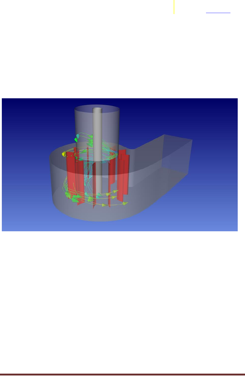
Rigid Body Motion for Multiple Rotating Reference Frame (MRF) solutions
Are you using Multiple Rotating Reference Frames (MRF) in your solver? There are a few
instances when utilizing the Rigid Body Motion capability in EnSight can provide a distinct advantage in
analyzing your results. If you are trying to evaluate streamlines in a MRF model within EnSight, you will
need the Rigid Body Motion capability. EnSight has an ability called “Rigid Body Motion” based on Euler
Transformations of both parts and vector variables as a function of time. How does this help? It is
common practice in many CFD codes to utilize a single reference of the grid, and either solve this
portion of the equations in a rotating reference frame (MRF), or apply a fixed rotation and solve a
transient solution. When operating in either of these types of situations, you can utilize EnSight’s Rigid
Body Motion to perform either simply visual rotation of the rotating parts, or to correctly integrate
pathlines through that region of the domain.
Initially, the Rigid Body Motion capability in EnSight was written to dynamically move geometry from
FEA or Rigid Body Solvers according to the commonly used “Euler Transformations”. This capability was
expanded to support its application in CFD models as well. The general capability of Rigid Body Motion
in EnSight allows for generic per part application of euler transformations of both the part’s coordinates
as well as vector quantities, so that you may use it to describe any rigid body motion. However, this
discussion here is focused on a common subset of this generic motion : Fixed rotation rate about an axis.
As this is a common requirement found in all types of analyses from pumps to hvac units, fans, stir
tanks, or turbomachinery, we have constructed a short User Defined Tool to ease the setup of the Rigid
Body Motion. This document will focus on the use of this tool for fixed rotate rate about an axis.
Example Dataset
An Example Dataset can be download here.
An example tutorial using this dataset and the UserDefinedTool for Rigid Body Motion setup :
Introduction to Using RBM in EnSight
Caveats:
Users should be using EnSight Case Gold format files.
Users ‘can’ setup multiple rotating parts, but this tool does not cater to that use-case.
No solvers exporting to EnSight Case Gold format currently take advantage of this, so users will have to
be aware of this capability, how to setup, and when to use it correctly.
Uses:
Transition Assistance from Fluent to EnSight Page 23
ANSYS, Inc.
2166 N Salem Street, Ste 101
Apex, NC 27523 www.ansys.com
Solver generated a single solution for an MRF solved domain. Pathlines + Rigid Body Motion will be
required to obtain correct integration of particle traces through moving domain.
Solver generated transient solution with fixed rotation of the grid. Rather than multiple Geometry files
for EnSight to load for each timestep, users should revert to a single geometry file + rigid body motion
setup to create efficient operation of EnSight.
Fixed motion boundary values (tires rotating). Use of Rigid Body Motion can be utilized to visualize the
rotation of the boundary. This is purely a visual alternative to frame mode rotation.

Transition Assistance from Fluent to EnSight Page 24
ANSYS, Inc.
2166 N Salem Street, Ste 101
Apex, NC 27523 www.ansys.com
Discrete Phase Handling (Particle Tracks)
EnSight can handle Discrete Phase information (i.e. particle tracks, droplets, solid objects,
discrete elements) into the post processing along with the typical continuous phase information. In
specific regards to Fluent Particle data, you can visit these two instructional videos on the basics of
getting your discrete phase data into EnSight:
Fluent Export of particle data to EnSight https://vimeo.com/146143322
Handling multiple injections: https://support.ceisoftware.com/hc/en-us/articles/203576198-Fluent-
Particle-Data-with-Multiple-Injections

Transition Assistance from Fluent to EnSight Page 25
ANSYS, Inc.
2166 N Salem Street, Ste 101
Apex, NC 27523 www.ansys.com
Limitations for Fluent to EnSight
Separate to the items listed above, there are known caveats and limitations with the export of
data from Fluent to EnSight format. These are captured in the Fluent Documentation. Presented below
are a list of the currently known items, and their reference into the online Fluent Documentation:
1. Changing Cell Zone Transient Datasets.
Important:
If the files that are exported during multiple transient simulations are to be used as a set, you should run
all of the simulations on the same platform, using the same number of processors. This ensures that all
of the files are compatible with each other.
Note: If you selected EnSight Case Gold from the File Type drop-down list, ANSYS Fluent does not
support exporting data files to EnSight during a transient calculation in which a new cell zone or surface
is created after the calculation has begun (as can be the case for an in-cylinder simulation, for example).
Link:
https://ansysproducthelpqa.win.ansys.com/account/secured?returnurl=/Views/Secured/corp/v190/flu_
ug/flu_ug_FileExportTransient_soln.html
2. EnSight Encas File name
Important: If you do not specify an EnSight Encas File Name, you will have to manually create an
appropriate .encas file.
Link:
https://ansysproducthelpqa.win.ansys.com/account/secured?returnurl=/Views/Secured/corp/v190/flu_
ug/flu_ug_FileExportTransient_part.html
3. Exporting Particle Data
Important: If you plan to export particle data to EnSight, you should first verify that you have already
written the files associated with the EnSight Case Gold file type by using the File/Export/Solution Data...
ribbon tab option.
Link:
https://ansysproducthelpqa.win.ansys.com/account/secured?returnurl=/Views/Secured/corp/v190/flu_
ug/flu_ug_sec_particle_history_export.html
4. User Defined Surfaces/Created Surfaces
Note: Data on user defined/created surfaces is not available for export to EnSight Case Gold file format.
Important:
For non-stationary reference zones, all the velocities are exported to EnSight as velocities relative to the
selected reference zone. See the informational note in Data Explorer Files for further details.
ANSYS Fluent supports exporting polyhedral data to EnSight.
Transition Assistance from Fluent to EnSight Page 26
ANSYS, Inc.
2166 N Salem Street, Ste 101
Apex, NC 27523 www.ansys.com
Link :
https://ansysproducthelpqa.win.ansys.com/account/secured?returnurl=/Views/Secured/corp/v190/flu_
ug/flu_ug_file_export_esight.html
5. Stationary/Rotating Zone
Important: When you are exporting data for Data Explorer, EnSight Case Gold, or I-deas Universal and
the reference zone is not a stationary zone, the data in the velocity fields is exported by default as
velocities relative to the motion specification of that zone. This data is always exported, even if you do
not choose to export any scalars. Any velocities that you select to export as scalars in the Quantities list
(for example, X Velocity, Y Velocity, Radial Velocity, and so on) are exported as absolute velocities. For
all other types of exported files, the velocities exported by default are absolute velocities.
Link:
https://ansysproducthelpqa.win.ansys.com/account/secured?returnurl=/Views/Secured/corp/v190/flu_
ug/flu_ug_file_export_data.html
6. Exporting Pathlines
Important: If you plan to write the pathline data in EnSight format, you should first verify that you have
already written the files associated with the EnSight Case Gold file type by using the File/Export...
ribbon tab option.
Link:
https://ansysproducthelpqa.win.ansys.com/account/secured?returnurl=/Views/Secured/corp/v190/flu_
ug/flu_ug_sec_graphics_pathlines.html%23x1-202200030.37
