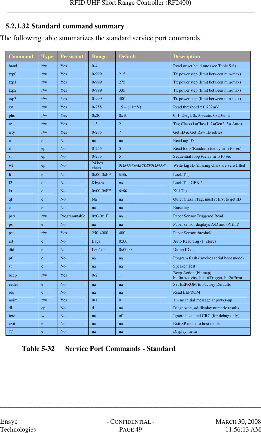
Ensyc Technologies RF24BLK UHF (900 MHz) RFID Reader User Manual RF2400 Spec rev1 0 071128
Ensyc Technologies UHF (900 MHz) RFID Reader RF2400 Spec rev1 0 071128
UserManual.wiki
>
Ensyc Technologies
>
RF24BLK User Manual
User Manual
Navigation menu
Upload a User Manual
Namespaces
Wiki Guide
HTML
PDF
Info
Views
User Manual
Discussion / Help
Navigation
![________________________________________________________________________ PRODUCT SPECIFICATION ii 5.2.1.2 Transmit Power Step (Txp[0-3]) command...................................37 5.2.1.3 Receive Threshold (rxt) command ................................................38 5.2.1.4 Phase (phs) command....................................................................38 5.2.1.5 Tag Class (tc) command ................................................................39 5.2.1.6 Read Retry (rrty) command...........................................................39 5.2.1.7 Read Tag (rt) command.................................................................39 5.2.1.8 Read Loop (rl) command...............................................................39 5.2.1.9 Sequential Loop (sl) command......................................................40 5.2.1.10 Write Tag (wt) command...............................................................40 5.2.1.11 Lock Tag (lt) command .................................................................40 5.2.1.12 Lock Tag G2 (l2) command...........................................................41 5.2.1.13 Access (apw)..................................................................................41 5.2.1.14 Kill Tag (kt) command...................................................................41 5.2.1.15 Quiet Tag (qt) command................................................................41 5.2.1.16 Erase Tag (et) command................................................................42 5.2.1.17 Paper Sensor Triggered Read (pstr) command..............................42 5.2.1.18 Paper Sensor (ps) command ..........................................................42 5.2.1.19 Paper Sensor Threshold (pst) command........................................43 5.2.1.20 Auto Read Tag (art) command......................................................43 5.2.1.21 Dump ID Data (did) command......................................................44 5.2.1.22 Program Flash (pf) command ........................................................44 5.2.1.23 Speaker Test (st) command............................................................44 5.2.1.24 Beep (beep) command ...................................................................45 5.2.1.25 Set EEPROM Defaults (eedef) command......................................45 5.2.1.26 Read EEPROM (ree) command.....................................................45 5.2.1.27 No initial message (noim) command .............................................45 5.2.1.28 Diagnostic (di) command ..............................................................46 5.2.1.29 Ignore CRC (icrc) command .........................................................48 5.2.1.30 Exit (exit) command.......................................................................48 5.2.1.31 Display menu (??) command.........................................................48 5.2.1.32 Standard command summary.........................................................49 5.2.2 Protected Commands.......................................................................................50 5.2.2.1 Password (pw) command...............................................................50 5.2.2.2 Transmit power (txp) command.....................................................50 5.2.2.3 Maximum transmit power (txpmax) command..............................50 5.2.2.4 Minimum transmit power (txpmin) command ...............................50 5.2.2.5 Channel select (chan) command....................................................51 5.2.2.6 Hop (hop) command......................................................................52 5.2.2.7 Gen2 Read (g2r) command ...........................................................52 5.2.2.8 Gen2 Write (g2w) command .........................................................52 5.2.2.9 Transmit zeros (t0) command........................................................52 5.2.2.10 Transmit ones (t1) command .........................................................53 5.2.2.11 Transmit alternating (ta) command ...............................................53 5.2.2.12 Transmit random (tr) command.....................................................53 5.2.2.13 Transmit data (td) command..........................................................53 5.2.2.14 Carrier on (con) command.............................................................54 5.2.2.15 Carrier off (coff) command............................................................54 5.2.2.16 Localization (local) command.......................................................54 5.2.2.17 Chipcon register read (ccr) command............................................54 5.2.2.18 Chipcon register write (ccw) command .........................................54 5.2.2.19 Protected command summary........................................................55 5.2.3 Service port error codes...................................................................................56 5.3 Radio Frequency Interface ................................................................................................57](https://usermanual.wiki/Ensyc-Technologies/RF24BLK/User-Guide-923324-Page-5.png)
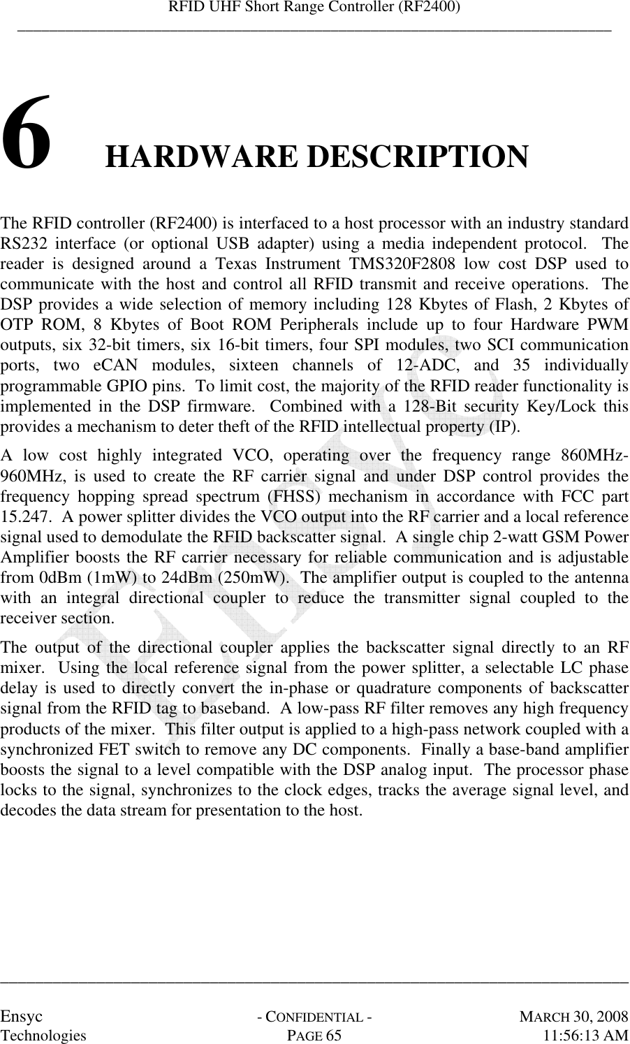
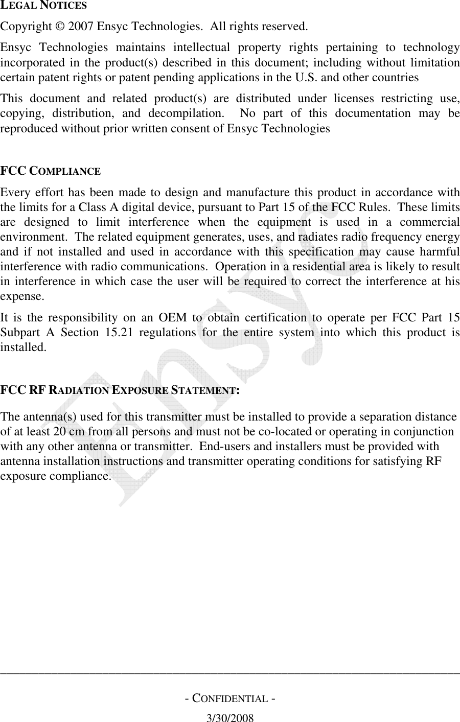
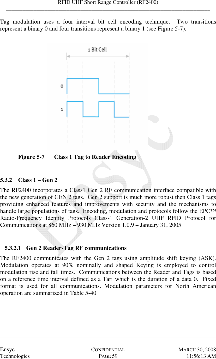
![RFID UHF Short Range Controller (RF2400) __________________________________________________________________________ ________________________________________________________________________ Ensyc - CONFIDENTIAL - MARCH 30, 2008 Technologies PAGE 12 11:56:13 AM 5.1.1.1 Message Packet Format Messages between the host and reader are binary data packets, consisting of a message payload encapsulated with two bytes preceding any message ([DLE][SOM]) and two bytes completing any message ([DLE][EOM]). All communications are initiated by the host. (Refer to Figure 5-1 and Table 5-1) Note: ITEMS IN PARENTHESIS (…) ARE NOT REQUIRED FOR ALL MESSAGES. [DLE] [SOM] [Payload] [DLE] [EOM] Figure 5-1 Message Packet Format Token Description [DLE] Data Link Escape token; 0x10 [SOM] Start of Message token; 0x01 [EOM] End of Message token; 0x02 Table 5-1 Message Encapsulation Characters In order to avoid ambiguities, if a data value in the payload is a DLE (0x10) character, the DLE (0x10) is repeated as the message packet is formed. 5.1.1.2 Host-to-Reader Payload The host to reader payload includes a session identification [SessionID], a target reader number [Reader#], a command to execute [Command], optional command data (CommandData), followed by a two byte CRC [CRC-CCITT16]. (Refer to Figure 5-2 and Table 5-2) [SessionID] [Reader#] [Command] (CommandData) [CRC-CCITT-16] Figure 5-2 Host to Reader Payload Format](https://usermanual.wiki/Ensyc-Technologies/RF24BLK/User-Guide-923324-Page-21.png)
![RFID UHF Short Range Controller (RF2400) __________________________________________________________________________ ________________________________________________________________________ Ensyc - CONFIDENTIAL - MARCH 30, 2008 Technologies PAGE 13 11:56:13 AM 5.1.1.3 Reader-to-Host Payload The reader to host payload includes a session identification [SessionID], a target reader number [Reader#], the command executed [CommandEcho], type of communication [CommCode], optional response data (ResponseData), followed by a two byte CRC [CRC-CCITT16]. (Refer to Figure 5-3, Table 5-2 and Table 5-3) [SessionID] [Reader#] [CommandEcho] [CommCode] (ResponseData) [CRC-CCITT16] Figure 5-3 Reader to Host Payload Format Payload Field Description [SessionID] Single-byte value. Every command gets a new number defined by the host. Every response matches the session ID of the initiating command. Normal session IDs can range from 0x01 to 0xFF. A SessionID of 0x00 in a command message forces the reader to repeat the previous response. This feature allows the Host to request the previous response in case of a communication error. [Reader # ] Single-byte value. In a Host command, a Reader # of 0x00 indicates that the command is addressed to all readers. A Reader will reply to commands only if its internal RDRNUM matches or if a command is addressed to all readers The factory default reader number is 0xFF. [Command] [CommandEcho] Single-byte value. Defines the command to be executed or has been executed (refer to section 5.1.2 for details). (CommandData) Variable length value specifying command parameters (refer to the section 5.1.2 for details) [CommCode] Single-byte value. Indicates the type of message or error. CommType < 0x80 indicates that a valid command was received. CommType >= 0x80 indicates that an error occurred, either in the command format, parameters, or in the execution of the command. (refer to Table 5-3 for details) (ResponseData) Contains a variable number of bytes (including none) (refer to section 5.1.1.4 for details). [CRC-CCITT16] Two bytes of CRC-CCITT16 polynomial (X^16+X^12+X^5+1) seed 0xFFFF. The CRC is calculated over all data from Session ID to Response Data inclusive. DLE packetization is not included into the CRC. The CRC is sent MSB first, LSB last. Table 5-2 Command/Response Payload Fields](https://usermanual.wiki/Ensyc-Technologies/RF24BLK/User-Guide-923324-Page-22.png)
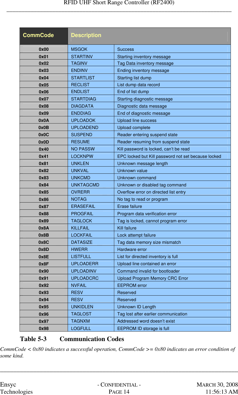
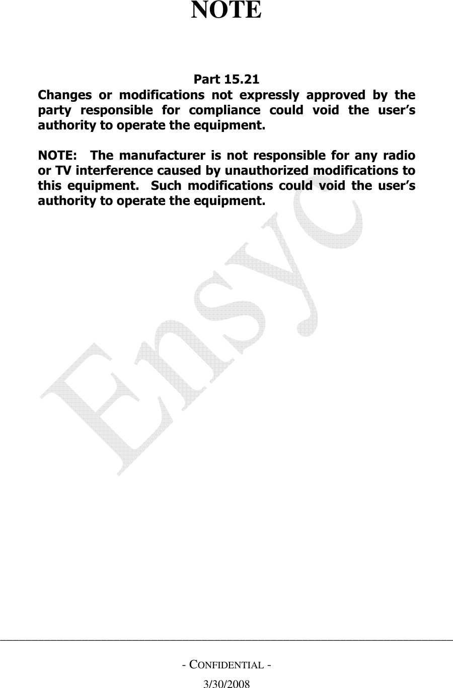
![RFID UHF Short Range Controller (RF2400) __________________________________________________________________________ ________________________________________________________________________ Ensyc - CONFIDENTIAL - MARCH 30, 2008 Technologies PAGE 15 11:56:13 AM 5.1.1.4 Response Data Formats The following sub-sections detail specific response data formats 5.1.1.4.1 Simple Command Response The RF2400 reader responds to a simple command (for example getting a reader parameter) with the specified number of bytes. 5.1.1.4.2 Low-Level Command Response In response to a tag-related low-level command such as Get Tag ID. The Response Data is sent to the Host in the following format (Refer to Figure 5-4 and Table 5-4) [TagDecodeStatus] [Antenna#] (TagDataLength) (TagData) Figure 5-4 Low-Level Command Response Low-Level Field Description [TagDecodeStatus] Single-byte value indicating status of data acquisition by a low-level command 0x00 – Good ID 0x01 – No tag 0x02 – Collision 0x03 – CRC Error (returned for Get Tag ID only) Bit4 – Kill password is locked Bit5 – Access password is locked [Antenna # ] Single-byte value indicating the Antenna number used for the current air interface transaction. The only valid value for the RF2400 is 0x00 (TagDataLength) Length of Tag Data in bytes Included for TagDecodeStatus of 0x00 "GoodID and 0x03 "CRC Error" only (TagData) Variable length defined by TagDataLength. Data is sent MSB first ending with the LSB of the last byte. Included for TagDecodeStatus of 0x00 "GoodID and 0x03 "CRC Error" only Table 5-4 Low-Level Response Fields 5.1.1.4.3 Error Response The RF2400 reader responds to every host command except when a communication error is detected. If a reader detects a CRC Error in a host payload, the message will be ignored. However, if the host detects a CRC Error, it may request the previous response by sending a packet with a [SessionID] of zero. If the host payload is less than four bytes long including the two bytes of CRC (no Reader# or Command) the reader will ignore the message. If the payload is four bytes](https://usermanual.wiki/Ensyc-Technologies/RF24BLK/User-Guide-923324-Page-24.png)
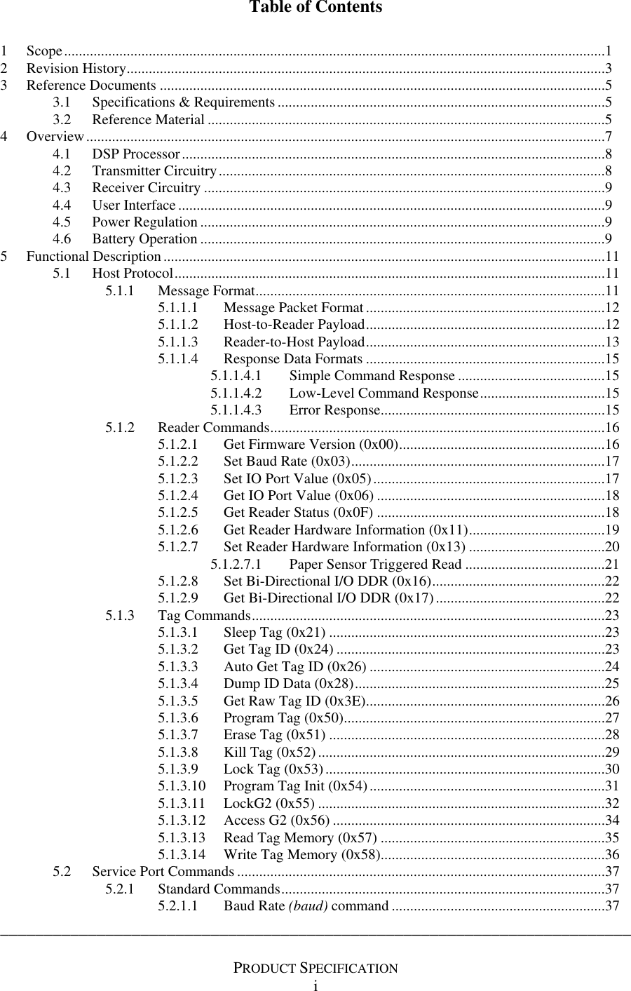
![RFID UHF Short Range Controller (RF2400) __________________________________________________________________________ ________________________________________________________________________ Ensyc - CONFIDENTIAL - MARCH 30, 2008 Technologies PAGE 16 11:56:13 AM long including the two bytes of CRC (no Command), the reader will respond with a 0x81 UNKLEN “unknown message length” [CommCode]. 5.1.2 Reader Commands The RF2400 controller responds to numerous commands using the media independent format described in paragraph 5.1. These commands provide a mechanism to configure (Set) the reader as well as retrieve (Get) reader status. The reader will respond to all Set commands with an echo of [SessionID], [Reader#], [CommandEcho], and [CommCode] followed by a two byte CRC [CRC-CCITT16] as described in paragraph 5.1.1.3. The reader will respond to all Get commands with an echo of [SessionID], [Reader#], [CommandEcho], [CommCode] and a variable length (ResponseData) field followed by a two byte CRC [CRC-CCITT16] as described in paragraphs 5.1.1.3 and 5.1.1.4. Any command may result in a [CommCode] of one of the following: MSGOK, UNKLEN, UNKVAL, and UNKCMD as defined in Table 5-1. Other possible codes are identified in the description of the specific command. If the RF2400 has been initialized into its integral bootloader firmware, there will be no response to host reader commands 5.1.2.1 Get Firmware Version (0x00) The Reader will reply with five (5) bytes specifying Localization Code, Reader Type, and Firmware Version Number. Response data is in binary hex format. The localization code and the reader type are stored in non-volatile memory and automatically configured for USA (0x01) operation on the initial firmware upload. Subsequent firmware updates preserve the existing configuration in non-volatile memory. Command Data Response Date Command Code Size Valid Values Size Valid Values 0x00 0 Bytes -- 5 Byte 1st Byte -- Localization Code 0x01 -- USA 0x02 -- Japan 0x03 -- E.U. 2nd Byte -- Reader Type 0x09 – RF1200 Reader 0x0A – RF2400 Reader 3rd Byte -- 0x00 4th Byte -- Major Revision # 5th Byte -- Minor Revision # Table 5-5 Get Firmware Version COMMAND DLE SOM SesID Rdr# Cmd CRCH CRCL DLE EOM 10 01 01 FF 00 54 0C 10 02 RESPONSE DLE SOM SesID Rdr# Echo Mtype Local Rtype Nused FverH FverL CRCH CRCL DLE EOM 10 01 01 FF 00 00 01 09 00 00 0A 75 A8 10 02 Get Firmware Version Example Note: this example reflects firmware version V0.10](https://usermanual.wiki/Ensyc-Technologies/RF24BLK/User-Guide-923324-Page-25.png)
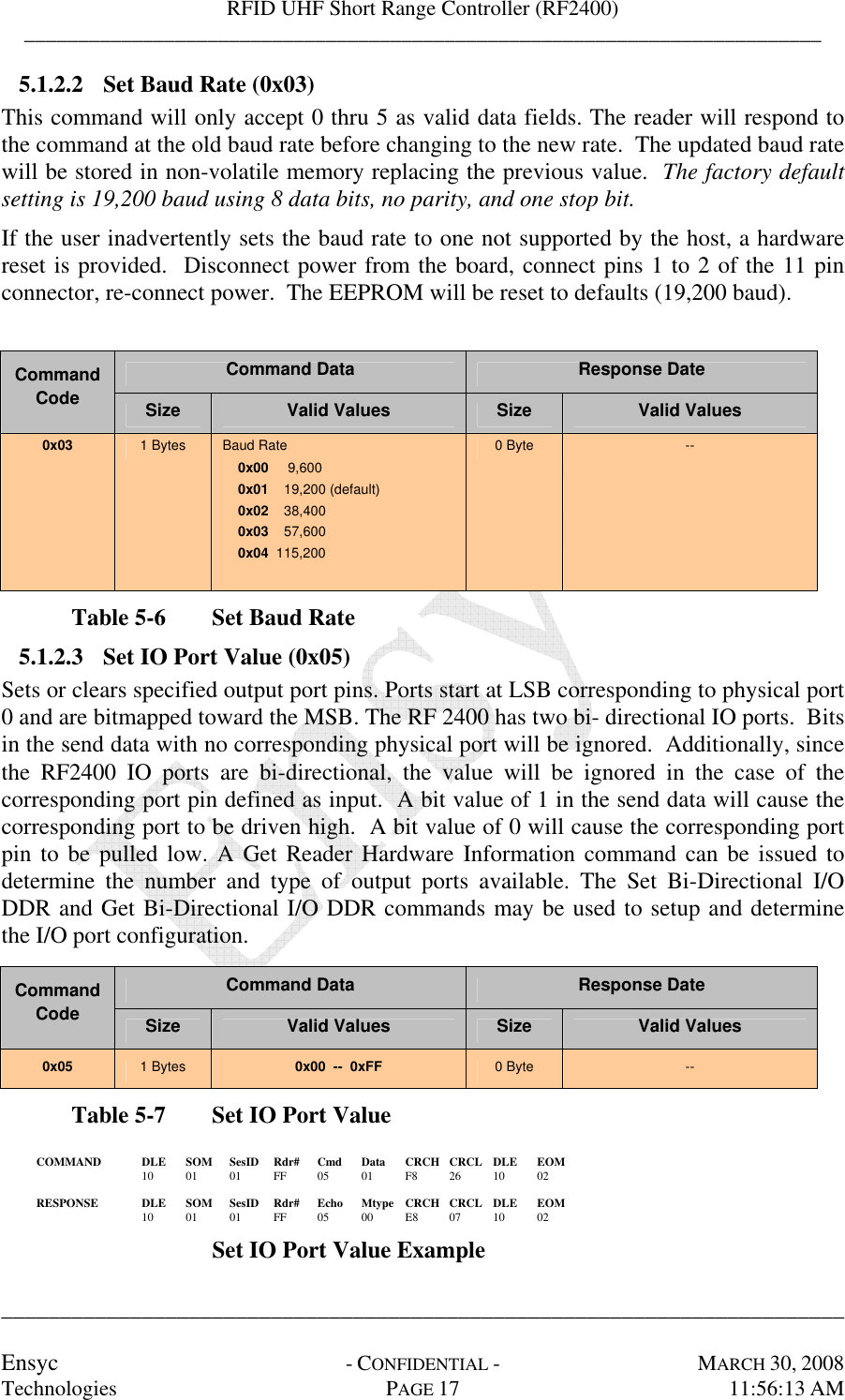
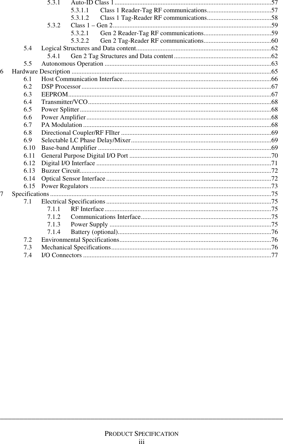
![RFID UHF Short Range Controller (RF2400) __________________________________________________________________________ ________________________________________________________________________ Ensyc - CONFIDENTIAL - MARCH 30, 2008 Technologies PAGE 20 11:56:13 AM 5.1.2.7 Set Reader Hardware Information (0x13) The Set Reader Hardware Information command provides a mechanism for the host to establish various aspects of the hardware. Command Data values are used to select specific parameters. Command Data Response Date Command Code Size Byte Valid Values Size Valid Values 2 Byte 1st 2nd 0x02 – Set Flags Bitmap Bit 0 – set to ignore host cmd CRC 0 Bytes 1 Byte 1st 0x06 – Localization Code (2) 1 Byte Reader Type 0x09 -- Single RFID Reader 1 Byte 1st 0x07 – Radio Type (2) 1 Byte Upper Nibble -- # of Antennas 0x0X -- One Antenna Lower Nibble – Frequency Band 0xX1 -- 868MHz 0xX2 -- 915MHz 0xX3 -- 950MHz 2 Bytes 1st 2nd 0x11 – Tag Class Bitmap: bit 0 – Class1 bit 1 – Gen2 Both set = auto detect 0 Bytes -- 2 Bytes 1st 2nd 0x17 – Paper Sensor Trigger Pstrs Bitmap: bit 0 – enable bit 1 – 0= reflection, 1= no reflection bit 2 – is ignored bit 3 – persistent bit 4 – use switch instead of sensor bit 5 – Store ID in EEPROM 0 Bytes -- 2 Bytes 1st 2nd 0x18 – Set TagID & Raw ID Retries # Retries 0 Bytes Def = 7-- 3 Bytes 1st 2,3 0x20 – Set Tx power step 0 Tx power 0 Bytes 3 Bytes 1st 2,3 0x21 – Set Tx power step 1 Tx power 0 Bytes 3 Bytes 1st 2,3 0x22 – Set Tx power step 2 Tx power 0 Bytes 3 Bytes 1st 2,3 0x23 – Set Tx power step 3 Tx power 0 Bytes 0x13 2 Bytes 1st 2nd 0x24 – Set Receive Threshold Threshold [102 (0x66) = 75mV] 0 Bytes Table 5-11 Set Reader Hardware Information (2) These commands are not yet implemented (unknown value Message Type returned) COMMAND DLE SOM SesID Rdr# Cmd Sub Data CRCH CRCL DLE EOM 10 01 01 FF 13 02 01 5E 62 10 02 RESPONSE DLE SOM SesID Rdr# Echo Mtype CRCH CRCL DLE EOM 10 01 01 FF 13 00 xx xx 10 02 Set Reader Hardware Example (Ignore CRC)](https://usermanual.wiki/Ensyc-Technologies/RF24BLK/User-Guide-923324-Page-29.png)
![RFID UHF Short Range Controller (RF2400) __________________________________________________________________________ ________________________________________________________________________ Ensyc - CONFIDENTIAL - MARCH 30, 2008 Technologies PAGE 30 11:56:13 AM 5.1.3.9 Lock Tag (0x53) The LOCK command sets and verifies the tag kill code. For Class 1 tags the lock code [0xA5] is also verified (Gen 2 has no lock code). This establishes the tag kill code and locks the tag preventing any further modification of the tag ID, or CRC. The command begins with a tag search which repeats up to the given number of find tag retries or until a valid tag is found. Subsequently, the Lock command is iterated up the number of lock retries or for Class 1 until the tag read response consists of only the CRC followed by the 12 bytes of Tag ID data indicating LOCK is verified. Note the kill code and lock code are not backscattered on locked Class 1 tags. For Gen 2 tags after the kill password is written both the EPC and kill password are locked and the tag response indicates success or failure which verifies the LOCK. Note the kill password is not backscattered on locked Gen2 tags. Since The RF2400 only supports tags written in 96 bit format, the only valid ID length is twelve (0x0C). Additionally, the lock command will only function on tags previously written in a 96-bit format having an IDLEN of 12 bytes. A successful operation is determined if LOCK is verified. If successful a MSGOK will be returned otherwise an error code indicating the failure will be returned. Error codes (CommCode) include HWERR, UNKTAGCMD, NOTAG, DATASIZE, TAGLOST, TAGLOCK, and LOCKFAIL. Command Data Response Date Command Code Size Valid Values Size Valid Values 0x50 7 Bytes 1st Byte—Tag Retries 0x00-0xFF 2nd Byte--Lock attempts 0x01-0xFF 3rd Byte-- ID Length 0x0C 4th – 7th Bytes Class 1 (first byte only) KILL code 0x00-0xFF Gen2 (all four bytes) kill password 0x00000000 – 0xFFFFFFFF 0 Bytes -- Table 5-22 Lock Tag](https://usermanual.wiki/Ensyc-Technologies/RF24BLK/User-Guide-923324-Page-39.png)
![RFID UHF Short Range Controller (RF2400) __________________________________________________________________________ ________________________________________________________________________ Ensyc - CONFIDENTIAL - MARCH 30, 2008 Technologies PAGE 37 11:56:13 AM 5.2 SERVICE PORT COMMANDS In addition to the binary message format, the RF2400 supports an ASCII communication mode providing a service menu using the existing RS232 interface. The RF2400 powers up accepting binary messages as described in section 5.1 above and posts a single line message containing the current version of the firmware. To activate the service menu, it is necessary to send the proper token lead-in sequence ([DLE][SMR]) as shown in Table 5-30. Two sets of commands are available; standard and protected provide user and factory/service personnel associated command and configuration menus. Token Description [DLE] Data Link Escape token; 0x10 (^p) [SMR] Service mode token; 0x04 (^d) Table 5-30 Service Port Lead-in sequence 5.2.1 Standard Commands Standard commands are available to all users and are documented in this specification. These commands provide a means to test the basic operation of the reader and to configure several operating parameters. Note all operating parameters can be returned to the factory defaults by installing the jumper JX and powering cycling the board. 5.2.1.1 Baud Rate (baud) command The baud rate (baud) command allows the user to reconfigure the RS232 interface baud rate. There are six baud rates available ranging from 9,600 baud to 115200 baud. Baud rates are represented using a single decimal parameter from 0 to 5: baud 0 = 9600, baud 1 = 19200, baud 2 = 38400, baud 3 =57600, and baud 4 = 115200,. The default RS232 configuration is 19,200 baud using 8 data bits, 1 stop bit, and no parity. The current baud rate is read using the baud <CR> and is displayed as a 0-4. A new baud rate is selected using baud=n<CR> where n represents the rate selected from 0-4. The current baud rate remains in effect until the new rate has been entered and the command line displays the command prompt. 5.2.1.2 Transmit Power Step (Txp[0-3]) command The transmit power step (txp[0-3]) command is used to set the four transmit power steps used to access a tag. The RF2400 reader always starts at the lowest power and successively increases the power level until a valid tag is found. Each transmit power step is represented using a single decimal parameter from 0 to 3. The power level at a particular power step is read using the txp[0-3]<CR> command. The associated power levels are represented by a decimal number from 0 to 600 and represent the approximate power levels shown in Table 5-31. A new transmit level is established using txp[0-3]=n<CR> where n is a decimal number from 0 to 600. Upon completion the command prompt is displayed.](https://usermanual.wiki/Ensyc-Technologies/RF24BLK/User-Guide-923324-Page-46.png)
![RFID UHF Short Range Controller (RF2400) __________________________________________________________________________ ________________________________________________________________________ Ensyc - CONFIDENTIAL - MARCH 30, 2008 Technologies PAGE 50 11:56:13 AM 5.2.2 Protected Commands The protected commands are for test and setup by qualified service technicians. They allow setting of parameters for transmit power, channel hopping and frequency selection. Additionally, the PLL frequency synthesizer internal registers can be accessed. These settings can affect the legal operation of the unit and are only available to manufacturing and service personnel. These commands are hidden and only active when the proper password has been entered using the password command. 5.2.2.1 Password (pw) command The password (pw) command is used to enable the protected service port commands. The pw command is entered using pw=n<CR> where n is a decimal number from 0 to 65535. If you require access to the protected commands, contact Ensyc Technologies or your local service representative for the password. The board may be power cycled to disable the protected commands or enter an invalid password e.g. pw=0000. Upon completion, the command prompt is displayed. 5.2.2.2 Transmit power (txp) command The transmit power (txp) command is used to set or read the output transmit power. Using txp<CR> will display the current transmit power level setting as a decimal number from 0 to 600. Using txp=n<CR> where n is a decimal number from 0 to 600 will set the current transmit power level. This setting is not limited by the maximum and minimum transmit power limits. Upon completion, the command prompt is displayed. Power cycling the board or exiting the SP mode will return the transmit power level to the default txp[0] setting. Upon completion, the command prompt is displayed. 5.2.2.3 Maximum transmit power (txpmax) command The maximum transmit power (txpmax) command is used to set or read the maximum allowed output transmit power. Using txpmax<CR> will display the maximum transmit power level setting as a decimal number from 0 to 600. Using txpmax=n<CR> where n is a decimal number from 0 to 600 will set the maximum transmit power level (refer to Table 5-31 Transmit Power Level). Additionally any transmit power step setting greater then the maximum limit will be set to the maximum limit and a message “adjust steps” is displayed. Upon completion, the command prompt is displayed. 5.2.2.4 Minimum transmit power (txpmin) command The minimum transmit power (txpmin) command is used to set or read the minimum allowed output transmit power. Using txpmin<CR> will display the minimum transmit power level setting as a decimal number from 0 to 600. Using txpmin=n<CR> where n is a decimal number from 0 to 600 will set the minimum transmit power level (refer to Table 5-31 Transmit Power Level). Additionally any transmit power step setting less then the maximum limit will be set to the minimum limit and a message “adjust steps” is displayed. Upon completion, the command prompt is displayed.](https://usermanual.wiki/Ensyc-Technologies/RF24BLK/User-Guide-923324-Page-59.png)
![RFID UHF Short Range Controller (RF2400) __________________________________________________________________________ ________________________________________________________________________ Ensyc - CONFIDENTIAL - MARCH 30, 2008 Technologies PAGE 62 11:56:13 AM 5.4 LOGICAL STRUCTURES AND DATA CONTENT 5.4.1 Gen 2 Tag Structures and Data content The Gen 2 tag memory is logically separated into four banks. Each bank may contain zero or more memory words. The memory map follows. Bank Area MSB Content LSB xxh User [15:0] . . . 11 User 00h User [N:N-15] 0Fh . . . 10h TID [15:0] 1Fh 10 TID 00h TID [31:16] 0Fh xxh EPC [15:0] . . . 20h EPC [N:N-15] 2Fh 10h PC [15:0] 1Fh 01 EPC 00h CRC-16 [15:0] 0Fh . . . 30h Access Password [15:0] 3Fh 20h Access Password [31:16] 2Fh 10h Kill Password [15:0] 1Fh 00 Reserved 00h Kill Password [31:16] 0Fh Table 5-42 Class 1 Gen 2 Memory Map User Memory is for user specific data storage. This region is Tag vendor specific. TID memory contains an 8 bit allocation class identifier, and information to describe any custom capabilities of the Tag. The TID may include a Tag mask-designer identified, Tag model number, Tag serial number, etc EPC memory contains a CRC16 to protect the EPC, a Protocol Control (PC) field to describe the length of the EPC, and the EPC (Electronic Product Code). The RF2400 currently supports an EPC of 12 bytes. Reserved memory contains the kill and access passwords. The default (un-programmed) value of the both passwords is zero. An Interrogator can use the kill password once to kill a Tag and render it silent thereafter. The access password, if non-zero shall require the interrogator to issue this Password before transitioning to the secured state. .](https://usermanual.wiki/Ensyc-Technologies/RF24BLK/User-Guide-923324-Page-71.png)