Enterasys Networks 2G4072 52 Users Manual N Standalone Series Installation Guide
2G4072-52 to the manual f7cf01f5-9034-4f18-ab99-6f572623a47b
2015-02-04
: Enterasys-Networks Enterasys-Networks-2G4072-52-Users-Manual-366781 enterasys-networks-2g4072-52-users-manual-366781 enterasys-networks pdf
Open the PDF directly: View PDF ![]() .
.
Page Count: 70
- Enterasys Matrix® N Standalone Series Installation Guide
- Notice
- Contents
- Preface
- Introduction
- Network Requirements
- Installation
- Troubleshooting
- Specifications
- Mode Switch Bank Settings and Optional Installations
- Index

7.5x9-inch cover with bleed on 4 sides
Enterasys Matrix®
N Standalone Series
Installation Guide
2G4072-52
P/N 9033973-04

i
Notice
Enterasys Networksreservestherighttomakechangesinspecificationsandotherinformationcontainedinthis
documentanditswebsitewithoutpriornotice.ThereadershouldinallcasesconsultEnterasys Networksto
determinewhetheranysuchchangeshavebeenmade.
Thehardware,firmware,orsoftwaredescribedinthisdocumentissubjecttochangewithoutnotice.
INNOEVENTSHALLENTERASYS NETWORKSBELIABLEFORANYINCIDENTAL,INDIRECT,SPECIAL,OR
CONSEQUENTIALDAMAGESWHATSOEVER(INCLUDINGBUTNOTLIMITEDTOLOSTPROFITS)ARISING
OUTOFORRELATEDTOTHISDOCUMENT,WEBSITE,ORTHEINFORMATIONCONTAINEDINTHEM,EVEN
IFENTERASYS NETWORKSHASBEENADVISEDOF,KNEWOF,ORSHOULDHAVEKNOWNOF,THE
POSSIBILITYOFSUCHDAMAGES.
Enterasys Networks, Inc.
50MinutemanRoad
Andover,MA01810
©2008Enterasys Networks, Inc.Allrightsreserved.
PartNumber: 9033973‐04 July 2008
ENTERASYS NETWORKS, ENTERASYS MATRIX, LANVIEW, MATRIX, ENTERASYS NETSIGHT, WEBVIEW, and any
logos associated therewith, are trademarks or registered trademarks of Enterasys Networks, Inc., in the United States and other
countries.For a complete list of Enterasys trademarks, see http://www.enterasys.com/company/trademarks.aspx.
All other product names mentioned in this manual may be trademarks or registered trademarks of their respective companies.
DocumentationURL:http://www.enterasys.com/support/manuals
DocumentacionURL:http://www.enterasys.com/support/manuals
DokumentationimInternet:http://www.enterasys.com/support/manuals
Electrical Hazard: Only qualified personnel should perform installation procedures.
Riesgo Electrico: Solamente personal calificado debe realizar procedimientos de instalacion.
Elektrischer Gefahrenhinweis: Installationen sollten nur durch ausgebildetes und qualifiziertes Personal
vorgenommen werden.
ii
Regulatory Compliance Information
Federal Communications Commission (FCC) Notice
ThisdevicecomplieswithPart15oftheFCCrules.Operationissubjecttothefollowingtwoconditions:(1)thisdevice
maynotcauseharmfulinterference,and(2)thisdevicemustacceptanyinterferencereceived,includinginterference
thatmaycauseundesiredoperation.
NOTE: ThisequipmenthasbeentestedandfoundtocomplywiththelimitsforaclassAdigitaldevice,pursuantto
Part15oftheFCCrules.Theselimitsaredesignedtoprovidereasonableprotectionagainstharmfulinterferencewhen
theequipmentisoperatedinacommercialenvironment.Thisequipmentuses,generates,andcanradiateradio
frequencyenergyandifnotinstalledinaccordancewiththeoperator’smanual,maycauseharmfulinterferenceto
radiocommunications.Operationofthisequipmentinaresidentialareaislikelytocauseinterferenceinwhichcase
theuserwillberequiredtocorrecttheinterferenceathisownexpense.
WARNING: Changesormodificationsmadetothisdevicewhicharenotexpresslyapprovedbytheparty
responsibleforcompliancecouldvoidtheuser’sauthoritytooperatetheequipment.
Industry Canada Notice
ThisdigitalapparatusdoesnotexceedtheclassAlimitsforradionoiseemissionsfromdigitalapparatussetoutinthe
RadioInterferenceRegulationsoftheCanadianDepartmentofCommunications.
Leprésentappareilnumériquen’émetpasdebruitsradioélectriquesdépassantleslimitesapplicablesauxappareils
numériquesdelaclassAprescritesdansleRèglementsurlebrouillageradioélectriqueédictéparleministèredes
CommunicationsduCanada.
Class A ITE Notice
WARNING: ThisisaClassAproduct.Inadomesticenvironmentthisproductmaycauseradiointerferenceinwhich
casetheusermayberequiredtotakeadequatemeasures.
Clase A. Aviso de ITE
ADVERTENCIA:EsteesunproductodeClaseA.Enunambientedomésticoesteproductopuedecausarinterferencia
deradioencuyocasopuedeserrequeridotomarmedidasadecuadas.
Klasse A ITE Anmerkung
WARNHINWEIS:DiesesProduktzähltzurKlasseA(Industriebereich).InWohnbereichenkanneshierdurchzu
Funkstörungenkommen,dahersolltenangemesseneVorkehrungenzumSchutzgetroffenwerden.
Product Safety
Thisproductcomplieswiththefollowing:UL60950,CSAC22.2No.60950,2006/95/EC,EN60950,IEC60950,
EN 60825,21 CFR 1040.10.
Seguridad del Producto
ElproductodeEnterasyscumpleconlosiguiente:UL60950,CSAC22.2No.60950,2006/95/EC,EN 60950,IEC 60950,
EN 60825,21 CFR1040.10.
Produktsicherheit
DiesesProduktentsprichtdenfolgendenRichtlinien:UL60950,CSAC22.2No.60950,2006/95/EC,EN60950,IEC
60950,EN 60825,21CFR1040.10.
iii
Electromagnetic Compatibility (EMC)
Thisproductcomplieswiththefollowing:47CFRParts2and15,CSAC108.8,2004/108/EC,EN55022,EN61000‐3‐2,
EN 61000‐3‐3,EN55024,AS/NZSCISPR22,VCCIV‐3.
Compatibilidad Electromágnetica (EMC)
EsteproductodeEnterasyscumpleconlosiguiente:47CFRPartes2y15,CSAC108.8,2004/108/EC,EN55022,
EN 55024,EN 61000‐3‐2,EN61000‐3‐3,AS/NZSCISPR22,VCCIV‐3.
Elektro- magnetische Kompatibilität ( EMC )
DiesesProduktentsprichtdenfolgendenRichtlinien:47CFRParts2and15,CSAC108.8,2004/108/EC,EN55022,
EN 61000‐3‐2,EN61000‐3‐3,EN55024,AS/NZSCISPR22,VCCIV‐3.
Hazardous Substances
ThisproductcomplieswiththerequirementsofEuropeanDirective,2002/95/EC,RestrictionofHazardousSubstances
(RoHS)inElectricalandElectronicEquipment.
European Waste Electrical and Electronic Equipment (WEEE) Notice
InaccordancewithDirective2002/96/ECoftheEuropeanParliamentonwasteelectricalandelectronicequipment
(WEEE):
1. Thesymbolaboveindicatesthatseparatecollectionofelectricalandelectronicequipmentisrequiredandthatthis
productwasplacedontheEuropeanmarketafterAugust13,2005,thedateofenforcementforDirective
2002/96/EC.
2. Whenthisproducthasreachedtheendofitsserviceablelife,itcannotbedisposedofasunsortedmunicipalwaste.
Itmustbecollectedandtreatedseparately.
3. IthasbeendeterminedbytheEuropeanParliamentthattherearepotentialnegativeeffectsontheenvironment
andhumanhealthasaresultofthepresenceofhazardoussubstancesinelectricalandelectronicequipment.
4. Itistheusers’responsibilitytoutilizetheavailablecollectionsystemtoensureWEEEisproperlytreated.
Forinformationabouttheavailablecollectionsystem,pleasegotowww.enterasys.com/support/ orcontact
EnterasysCustomerSupportat35361705586(Ireland).
iv
ѻ
ѻક䇈ᯢк䰘ӊ
Supplement to Product Instructions
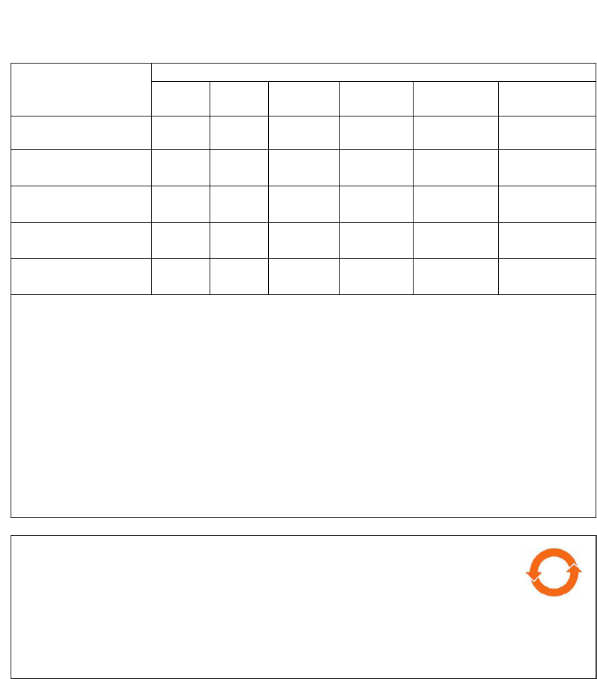
᳝↦᳝ᆇ⠽䋼ܗ㋴(Hazardous Substance)
䚼ӊৡ⿄
(Parts) 䪙
3E
∲
+J
䬝
&G
݁Ӌ䫀
&U
⒈㘨㣃
3%%
⒈Ѡ㣃䝮
3%'(
䞥ሲ䚼ӊ
(Metal Parts) hƻ ƻ h ƻ ƻ
⬉䏃ഫ
(Circuit Modules) hƻ ƻ h ƻ ƻ
⬉㓚ঞ⬉㓚㒘ӊ
(Cables & Cable Assemblies) hƻ ƻ h ƻ ƻ
ล᭭㘮ড়⠽䚼ӊ
(Plastic and Polymeric parts) ƻƻ ƻ ƻ ƻ h
⬉䏃ᓔ݇
(Circuit Breakers) ƻƻ h h ƻ ƻ
ƻ˖ 㸼⼎䆹᳝↦᳝ᆇ⠽䋼䆹䚼ӊ᠔᳝ഛ䋼ᴤ᭭Ёⱘ䞣ഛ SJ/T 11363-2006 ᷛޚ㾘ᅮⱘ䰤䞣㽕∖ҹϟDŽ
Indicates that the concentration of the hazardous substance in all homogeneous materials in the parts is
below the relevant threshold of the SJ/T 11363-2006 standard.
h˖ 㸼⼎䆹᳝↦᳝ᆇ⠽䋼㟇ᇥ䆹䚼ӊⱘᶤϔഛ䋼ᴤ᭭Ёⱘ䞣䍙ߎSJ/T 11363-2006 ᷛޚ㾘ᅮⱘ䰤䞣㽕∖DŽ
Indicates that the concentration of the hazardous substance of at least one of all homogeneous
materials in the parts is above the relevant threshold of the SJ/T 11363-2006 standard.
ᇍ䫔ଂП᮹ⱘ᠔ଂѻકᴀ㸼ᰒ⼎
߃߯կᑨ䫒ⱘ⬉ᄤֵᙃѻકৃ㛑ࣙ䖭ѯ⠽䋼DŽ⊼ᛣ᠔ଂѻકЁৃ㛑Ӯгৃ㛑ϡӮ᳝᠔᳝᠔߫ⱘ䚼ӊDŽ
This table shows where these substances may be found in the supply chain of Enterasys’ electronic
information products, as of the date of sale of the enclosed product. Note that some of the component types
listed above may or may not be a part of the enclosed product.
50
ℸ⦃ֱՓ⫼ᳳ䰤া䗖⫼ѢѻકᰃѻકݠЁ᠔㾘ᅮⱘᴵӊϟᎹ
The Environmentally Friendly Use Period (EFUP) for all enclosed products and their parts
are per the symbol shown here, unless otherwise marked. Certain parts may have a
different EFUP (for example, battery modules) and so are marked to reflect such. The
Environmentally Friendly Use Period is valid only when the product is operated under the
conditions defined in the product manual.
䰸䴲⡍߿ⱘᷛ⊼ℸᷛᖫЎ䩜ᇍ᠔⍝ঞѻકⱘ⦃ֱՓ⫼ᳳᷛᖫᶤѯ䳊䚼ӊӮ
᳝ϔϾϡৠⱘ⦃ֱՓ⫼ᳳ՟བ⬉∴ऩܗഫ䌈݊ѻકϞ

v
VCCI Notice
ThisisaclassAproductbasedonthestandardoftheVoluntaryControlCouncilforInterferencebyInformation
TechnologyEquipment(VCCI).Ifthisequipmentisusedinadomesticenvironment,radiodisturbancemayarise.
Whensuchtroubleoccurs,theusermayberequiredtotakecorrectiveactions.
BSMI EMC Statement — Taiwan
ThisisaclassAproduct.Inadomesticenvironmentthisproductmaycauseradiointerferenceinwhichcasetheuser
mayberequiredtotakeadequatemeasures.
vi
Safety Information
Class 1 Laser Transceivers
The single mode interface modules use Class 1 laser transceivers.
Read the following safety information before installing or operating these modules.
TheClass1lasertransceiversuseanopticalfeedbacklooptomaintainClass1operationlimits.Thiscontrolloop
eliminatestheneedformaintenancechecksoradjustments.Theoutputisfactoryset,anddoesnotallowanyuser
adjustment.Class1Lasertransceiverscomplywiththefollowingsafetystandards:
•21
CFR1040.10and1040.11U.S.DepartmentofHealthandHumanServices(FDA).
•IECPublication825(InternationalElectrotechnicalCommission).
• CENELECEN60825(EuropeanCommitteeforElectrotechnicalStandardization).
Whenoperatingwithintheirperformancelimitations,lasertransceiveroutputmeetstheClass1accessibleemission
limitofallthreestandards.Class1levelsoflaserradiationarenotconsideredhazardous.
Whentheconnectorisinplace,alllaserradiationremainswithinthefiber.Themaximumamountofradiantpower
exitingthefiber(undernormalconditions)is‐12.6dBmor55x10‐6watts.
Removingtheopticalconnectorfromthetransceiverallowslaserradiationtoemitdirectlyfromtheopticalport.The
maximumradiancefromtheopticalport(underworstcaseconditions)is0.8Wcm‐2or8x103Wm2sr‐1.
Donotuseopticalinstrumentstoviewthelaseroutput.Theuseofopticalinstrumentstoviewlaseroutput
increaseseyehazard.Whenviewingtheoutputopticalport,powermustberemovedfromthenetworkadapter.
Declaration of Conformity
ApplicationofCouncilDirective(s): 2004/108/EC
2006/95/EC
Manufacturer’sName: Enterasys Networks, Inc.
Manufacturer’sAddress: 50MinutemanRoad
Andover,MA01810
USA
EuropeanRepresentativeAddress: Enterasys Networks,Ltd.
NexusHouse,NewburyBusinessPark
LondonRoad,Newbury
BerkshireRG142PZ,England
ConformancetoDirective(s)/ProductStandards: ECDirective2004/108/EC
EN55022
EN61000‐3‐2
EN61000‐3‐3
EN55024
ECDirective2006/95/EC
EN60950
EN60825
EquipmentType/Environment: NetworkingEquipment,foruseinaCommercial
orLightIndustrialEnvironment.
Enterasys Networks, Inc.declaresthattheequipmentpackagedwiththisnoticeconformstotheabovedirectives.
vii
ENTERASYS NETWORKS, INC. FIRMWARE LICENSE AGREEMENT
BEFORE OPENING OR UTILIZING THE ENCLOSED PRODUCT,
CAREFULLY READ THIS LICENSE AGREEMENT.
Thisdocumentisanagreement(“Agreement”)betweentheenduser(“You”)andEnterasysNetworks,Inc.,onbehalf
ofitselfanditsAffiliates(ashereinafterdefined)(“Enterasys”)thatsetsforthYourrightsandobligationswithrespect
totheEnterasyssoftwareprogram/firmware(includinganyaccompanyingdocumentation,hardwareormedia)
(“Program”)inthepackageandprevailsoveranyadditional,conflictingorinconsistenttermsandconditions
appearingonanypurchaseorderorotherdocumentsubmittedbyYou.“Affiliate”meansanyperson,partnership,
corporation,limitedliabilitycompany,otherformofenterprisethatdirectlyorindirectlythroughoneormore
intermediaries,controls,oriscontrolledby,orisundercommoncontrolwiththepartyspecified.ThisAgreement
constitutestheentireunderstandingbetweentheparties,withrespecttothesubjectmatterofthisAgreement.The
Programmaybecontainedinfirmware,chipsorothermedia.
BYINSTALLINGOROTHERWISEUSINGTHEPROGRAM,YOUREPRESENTTHATYOUAREAUTHORIZEDTO
ACCEPTTHESETERMSONBEHALFOFTHEENDUSER(IFTHEENDUSERISANENTITYONWHOSEBEHALF
YOUAREAUTHORIZEDTOACT,“YOU”AND“YOUR”SHALLBEDEEMEDTOREFERTOSUCHENTITY)AND
THATYOUAGREETHATYOUAREBOUNDBYTHETERMSOFTHISAGREEMENT,WHICHINCLUDES,
AMONGOTHERPROVISIONS,THELICENSE,THEDISCLAIMEROFWARRANTYANDTHELIMITATIONOF
LIABILITY.IFYOUDONOTAGREETOTHETERMSOFTHISAGREEMENTORARENOTAUTHORIZEDTO
ENTERINTOTHISAGREEMENT,ENTERASYSISUNWILLINGTOLICENSETHEPROGRAMTOYOUANDYOU
AGREETORETURNTHEUNOPENEDPRODUCTTOENTERASYSORYOURDEALER,IFANY,WITHINTEN
(10)DAYSFOLLOWINGTHEDATEOFRECEIPTFORAFULLREFUND.
IFYOUHAVEANYQUESTIONSABOUTTHISAGREEMENT,CONTACTENTERASYSNETWORKS,LEGAL
DEPARTMENTAT(978)684‐1000.
YouandEnterasysagreeasfollows:
1. LICENSE. Youhavethenon‐exclusiveandnon‐transferablerighttouseonlytheone(1)copyoftheProgram
providedinthispackagesubjecttothetermsandconditionsofthisAgreement.
2. RESTRICTIONS. ExceptasotherwiseauthorizedinwritingbyEnterasys,Youmaynot,normayYoupermitany
thirdpartyto:
(a) Reverseengineer,decompile,disassembleormodifytheProgram,inwholeorinpart,includingforreasons
oferrorcorrectionorinteroperability,excepttotheextentexpresslypermittedbyapplicablelawandtothe
extentthepartiesshallnotbepermittedbythatapplicablelaw,suchrightsareexpresslyexcluded.
InformationnecessarytoachieveinteroperabilityorcorrecterrorsisavailablefromEnterasysuponrequest
anduponpaymentofEnterasys’applicablefee.
(b) IncorporatethePrograminwholeorinpart,inanyotherproductorcreatederivativeworksbasedonthe
Program,inwholeorinpart.
(c) Publish,disclose,copyreproduceortransmittheProgram,inwholeorinpart.
(d) Assign,sell,license,sublicense,rent,lease,encumberbywayofsecurityinterest,pledgeorotherwisetransfer
theProgram,inwholeorinpart.
(e) Removeanycopyright,trademark,proprietaryrights,disclaimerorwarningnoticeincludedonorembedded
inanypartoftheProgram.
viii
3. APPLICABLELAW. ThisAgreementshallbeinterpretedandgovernedunderthelawsandinthestateand
federalcourtsoftheCommonwealthofMassachusettswithoutregardtoitsconflictsoflawsprovisions.Youacceptthe
personaljurisdictionandvenueoftheCommonwealthofMassachusettscourts.Noneofthe1980UnitedNations
ConventionontheLimitationPeriodintheInternationalSaleofGoods,andtheUniformComputerInformation
TransactionsActshallapplytothisAgreement.
4. EXPORTRESTRICTIONS. YouunderstandthatEnterasysanditsAffiliatesaresubjecttoregulationbyagencies
oftheU.S.Government,includingtheU.S.DepartmentofCommerce,whichprohibitexportordiversionofcertain
technicalproductstocertaincountries,unlessalicensetoexporttheproductisobtainedfromtheU.S.Governmentor
anexceptionfromobtainingsuchlicensemayberelieduponbytheexportingparty.
IftheProgramisexportedfromtheUnitedStatespursuanttotheLicenseExceptionCIVundertheU.S.Export
AdministrationRegulations,YouagreethatYouareacivilenduseroftheProgramandagreethatYouwillusethe
Programforcivilendusesonlyandnotformilitarypurposes.
IftheProgramisexportedfromtheUnitedStatespursuanttotheLicenseExceptionTSRundertheU.S.Export
AdministrationRegulations,inadditiontotherestrictionontransfersetforthinSection1or2ofthisAgreement,You
agreenotto(i)reexportorreleasetheProgram,thesourcecodefortheProgramortechnologytoanationalofa
countryinCountryGroupsD:1orE:2(Albania,Armenia,Azerbaijan,Belarus,Cambodia,Cuba,Georgia,Iraq,
Kazakhstan,Laos,Libya,Macau,Moldova,Mongolia,NorthKorea,thePeople’sRepublicofChina,Russia,Tajikistan,
Turkmenistan,Ukraine,Uzbekistan,Vietnam,orsuchothercountriesasmaybedesignatedbytheUnitedStates
Government),(ii)exporttoCountryGroupsD:1orE:2(asdefinedherein)thedirectproductoftheProgramorthe
technology,ifsuchforeignproduceddirectproductissubjecttonationalsecuritycontrolsasidentifiedontheU.S.
CommerceControlList,or(iii)ifthedirectproductofthetechnologyisacompleteplantoranymajorcomponentofa
plant,exporttoCountryGroupsD:1orE:2thedirectproductoftheplantoramajorcomponentthereof,ifsuch
foreignproduceddirectproductissubjecttonationalsecuritycontrolsasidentifiedontheU.S.CommerceControl
ListorissubjecttoStateDepartmentcontrolsundertheU.S.MunitionsList.
5. UNITEDSTATESGOVERNMENTRESTRICTEDRIGHTS. TheenclosedProgram(i)wasdevelopedsolelyat
privateexpense;(ii)contains“restrictedcomputersoftware”submittedwithrestrictedrightsinaccordancewithsection
52.227‐19(a)through(d)oftheCommercialComputerSoftware‐RestrictedRightsClauseanditssuccessors,and(iii)in
allrespectsisproprietarydatabelongingtoEnterasysand/oritssuppliers.ForDepartmentofDefenseunits,the
ProgramisconsideredcommercialcomputersoftwareinaccordancewithDFARSsection227.7202‐3anditssuccessors,
anduse,duplication,ordisclosurebytheU.S.Governmentissubjecttorestrictionssetforthherein.
6. DISCLAIMEROFWARRANTY. EXCEPTFORTHOSEWARRANTIESEXPRESSLYPROVIDEDTOYOUIN
WRITINGBYENTERASYS,ENTERASYSDISCLAIMSALLWARRANTIES,EITHEREXPRESSORIMPLIED,
INCLUDINGBUTNOTLIMITEDTOIMPLIEDWARRANTIESOFMERCHANTABILITY,SATISFACTORY
QUALITY,FITNESSFORAPARTICULARPURPOSE,TITLEANDNON‐INFRINGEMENTWITHRESPECTTOTHE
PROGRAM.IFIMPLIEDWARRANTIESMAYNOTBEDISCLAIMEDBYAPPLICABLELAW,THENANYIMPLIED
WARRANTIESARELIMITEDINDURATIONTOTHIRTY(30)DAYSAFTERDELIVERYOFTHEPROGRAMTO
YOU.
7. LIMITATIONOFLIABILITY. INNOEVENTSHALLENTERASYSORITSSUPPLIERSBELIABLEFORANY
DAMAGESWHATSOEVER(INCLUDING,WITHOUTLIMITATION,DAMAGESFORLOSSOFBUSINESS,
PROFITS,BUSINESSINTERRUPTION,LOSSOFBUSINESSINFORMATION,SPECIAL,INCIDENTAL,
CONSEQUENTIAL,ORRELIANCEDAMAGES,OROTHERLOSS)ARISINGOUTOFTHEUSEORINABILITYTO
USETHEPROGRAM,EVENIFENTERASYSHASBEENADVISEDOFTHEPOSSIBILITYOFSUCHDAMAGES.
THISFOREGOINGLIMITATIONSHALLAPPLYREGARDLESSOFTHECAUSEOFACTIONUNDERWHICH
DAMAGESARESOUGHT.
THECUMULATIVELIABILITYOFENTERASYSTOYOUFORALLCLAIMSRELATINGTOTHEPROGRAM,
INCONTRACT,TORTOROTHERWISE,SHALLNOTEXCEEDTHETOTALAMOUNTOFFEESPAIDTO
ENTERASYSBYYOUFORTHERIGHTSGRANTEDHEREIN.
ix
8. AUDITRIGHTS. YouherebyacknowledgethattheintellectualpropertyrightsassociatedwiththeProgramare
ofcriticalvaluetoEnterasys,and,accordingly,Youherebyagreetomaintaincompletebooks,recordsandaccounts
showing(i)licensefeesdueandpaid,and(ii)theuse,copyinganddeploymentoftheProgram.Youalsograntto
Enterasysanditsauthorizedrepresentatives,uponreasonablenotice,therighttoauditandexamineduringYour
normalbusinesshours,Yourbooks,records,accountsandhardwaredevicesuponwhichtheProgrammaybedeployed
toverifycompliancewiththisAgreement,includingtheverificationofthelicensefeesdueandpaidEnterasysandthe
use,copyinganddeploymentoftheProgram.Enterasys’rightofexaminationshallbeexercisedreasonably,ingood
faithandinamannercalculatedtonotunreasonablyinterferewithYourbusiness.Intheeventsuchauditdiscovers
non‐compliancewiththisAgreement,includingcopiesoftheProgrammade,usedordeployedinbreachofthis
Agreement,YoushallpromptlypaytoEnterasystheappropriatelicensefees.Enterasysreservestheright,tobe
exercisedinitssolediscretionandwithoutpriornotice,toterminatethislicense,effectiveimmediately,forfailureto
complywiththisAgreement.Uponanysuchtermination,YoushallimmediatelyceasealluseoftheProgramandshall
returntoEnterasystheProgramandallcopiesoftheProgram.
9. OWNERSHIP. Thisisalicenseagreementandnotanagreementforsale.Youacknowledgeandagreethatthe
Programconstitutestradesecretsand/orcopyrightedmaterialofEnterasysand/oritssuppliers.Youagreeto
implementreasonablesecuritymeasurestoprotectsuchtradesecretsandcopyrightedmaterial.Allright,titleand
interestinandtotheProgramshallremainwithEnterasysand/oritssuppliers.Allrightsnotspecificallygrantedto
YoushallbereservedtoEnterasys.
10. ENFORCEMENT. YouacknowledgeandagreethatanybreachofSections2,4,or9ofthisAgreementbyYoumay
causeEnterasysirreparabledamageforwhichrecoveryofmoneydamageswouldbeinadequate,andthatEnterasys
maybeentitledtoseektimelyinjunctiverelieftoprotectEnterasys’rightsunderthisAgreementinadditiontoanyand
allremediesavailableatlaw.
11. ASSIGNMENT. Youmaynotassign,transferorsublicensethisAgreementoranyofYourrightsorobligations
underthisAgreement,exceptthatYoumayassignthisAgreementtoanypersonorentitywhichacquiressubstantially
allofYourstockassets.EnterasysmayassignthisAgreementinitssolediscretion.ThisAgreementshallbebinding
uponandinuretothebenefitoftheparties,theirlegalrepresentatives,permittedtransferees,successorsandassignsas
permittedbythisAgreement.Anyattemptedassignment,transferorsublicenseinviolationofthetermsofthis
AgreementshallbevoidandabreachofthisAgreement.
12. WAIVER. AwaiverbyEnterasysofabreachofanyofthetermsandconditionsofthisAgreementmustbein
writingandwillnotbeconstruedasawaiverofanysubsequentbreachofsuchtermorcondition.Enterasys’failureto
enforceatermuponYourbreachofsuchtermshallnotbeconstruedasawaiverofYourbreachorpreventenforcement
onanyotheroccasion.
13. SEVERABILITY. IntheeventanyprovisionofthisAgreementisfoundtobeinvalid,illegalorunenforceable,the
validity,legalityandenforceabilityofanyoftheremainingprovisionsshallnotinanywaybeaffectedorimpaired
thereby,andthatprovisionshallbereformed,construedandenforcedtothemaximumextentpermissible.Anysuch
invalidity,illegality,orunenforceabilityinanyjurisdictionshallnotinvalidateorrenderillegalorunenforceablesuch
provisioninanyotherjurisdiction.
14. TERMINATION. EnterasysmayterminatethisAgreementimmediatelyuponYourbreachofanyoftheterms
andconditionsofthisAgreement.Uponanysuchtermination,YoushallimmediatelyceasealluseoftheProgramand
shallreturntoEnterasystheProgramandallcopiesoftheProgram.
x

xi
Contents
Preface
Who Should Use This Guide ............................................................................................................... xv
Structure of This Guide ...................................................................................................................... xvi
Related Documents ........................................................................................................................... xvi
Document Conventions ......................................................................................................................xvii
Getting Help ......................................................................................................................................xviii
Chapter 1: Introduction
Overview of Enterasys Matrix N Standalone (NSA) Series Capabilities ............................................1-1
The 2G4072-52 ..................................................................................................................................1-2
Connectivity .......................................................................................................................................1-2
Management ......................................................................................................................................1-2
Switch Configuration Using WebView .........................................................................................1-2
Switch Configuration Using CLI Commands ...............................................................................1-3
Standards Compatibility .....................................................................................................................1-3
LANVIEW Diagnostic LEDs ...............................................................................................................1-3
Chapter 2: Network Requirements
Link Aggregation ................................................................................................................................2-1
10BASE-T Network ............................................................................................................................2-2
100BASE-TX Network .......................................................................................................................2-2
1000BASE-SX/SX+/LX Network ........................................................................................................2-2
1000BASE-T Network ........................................................................................................................2-2
Chapter 3: Installation
Unpacking the 2G4072-52 .................................................................................................................3-1
Rack Mounting ...................................................................................................................................3-2
Connecting Power ..............................................................................................................................3-4
Connecting to the Network .................................................................................................................3-5
Connecting UTP Cables ..............................................................................................................3-5
Connecting Fiber-Optic Cables to Mini-GBICs ............................................................................3-9
Connecting to the COM Port for Local Management .......................................................................3-13
What Is Needed .........................................................................................................................3-13
Connecting to an IBM PC or Compatible Device .......................................................................3-13
Connecting to a VT Series Terminal ..........................................................................................3-14
Connecting to a Modem ............................................................................................................3-15
Adapter Wiring and Signal Assignments ...................................................................................3-17
Completing the Installation ...............................................................................................................3-18
xii
Chapter 4: Troubleshooting
Using LANVIEW .................................................................................................................................4-1
Troubleshooting Checklist ..................................................................................................................4-4
Overview of Shutdown Procedure .....................................................................................................4-5
Recommended Shutdown Procedure Using RESET Button .......................................................4-6
Last Resort Shutdown Procedure Using RESET Button .............................................................4-6
Appendix A: Specifications
2G4072-52 Specifications ................................................................................................................. A-1
Mini-GBIC Input/Output Specifications ............................................................................................. A-2
Gigabit Ethernet Specifications ......................................................................................................... A-3
MGBIC-LC01 / MGBIC-MT01 Specifications (1000BASE-SX) ................................................... A-3
MGBIC-LC03 Specifications (1000BASE-SX) ............................................................................ A-3
MGBIC-LC09 Specifications (1000BASE-LX) ............................................................................ A-4
MGBIC-08 Specifications (1000BASE-ELX) .............................................................................. A-5
MGBIC-02 Specifications (1000BASE-T) ................................................................................... A-5
COM Port Pinout Assignments ......................................................................................................... A-6
Regulatory Compliance ..................................................................................................................... A-6
Appendix B: Mode Switch Bank Settings and Optional Installations
Required Tools .................................................................................................................................. B-2
Setting the Mode Switches ............................................................................................................... B-2
Memory Locations and Replacement Procedures ............................................................................ B-4
Location of DIMM and DRAM SIMM Memory Modules .............................................................. B-4
DIMM Replacement Procedure .................................................................................................. B-5
Index
xiii
Figures
1-1 2G4072-52 Front Panel..........................................................................................................1-2
1-2 LANVIEW LEDs .....................................................................................................................1-3
3-1 Attaching Rack-mount Ears to Enterasys Matrix N SA 2G4072-52 .......................................3-3
3-2 Mounting Enterasys Matrix N SA 2G4072-52 to Rack...........................................................3-3
3-3 Connecting Power..................................................................................................................3-4
3-4 Connecting a Twisted Pair Segment to the 2G4072-52.........................................................3-6
3-5 Crossover Four-Wire Cable RJ45 Pinouts.............................................................................3-7
3-6 Straight-Through Four-Wire Cable RJ45 Pinouts ..................................................................3-7
3-7 Eight-Wire Crossover Cable RJ45 Pinouts ............................................................................3-8
3-8 Eight-Wire Straight-Through Cable RJ45 Pinouts..................................................................3-8
3-9 Cable Connection to MT-RJ Fiber-Optic Connectors...........................................................3-10
3-10 Cable Connection to LC01 or LC09 Fiber-Optic Connectors...............................................3-11
3-11 Cable Connection to LC03 Fiber-Optic Connectors.............................................................3-12
3-12 Connecting an IBM PC or Compatible .................................................................................3-14
3-13 Connecting a VT Series Terminal ........................................................................................3-15
3-14 Connecting to a Modem.......................................................................................................3-16
3-15 Matrix Startup Screen Example (N7 Chassis)......................................................................3-20
4-1 LANVIEW LEDs .....................................................................................................................4-2
4-2 RESET Button........................................................................................................................4-6
B-1 Mode Switch Location........................................................................................................... B-3
B-2 DIMM and DRAM SIMM Locations ....................................................................................... B-4
B-3 Removing the Existing DIMM................................................................................................ B-5
B-4 Installing the DIMM ............................................................................................................... B-6
B-5 Removing Chassis Cover...................................................................................................... B-7
B-6 DRAM SIMM Connector Location......................................................................................... B-8
B-7 Installing the DRAM SIMM .................................................................................................... B-9
Tables
3-1 Contents of 2G4072-52..........................................................................................................3-2
4-1 LANVIEW LEDs .....................................................................................................................4-2
4-2 Troubleshooting Checklist......................................................................................................4-4
A-1 Specifications........................................................................................................................ A-1
A-2 Mini-GBIC Input/Output Port Specifications.......................................................................... A-2
A-1 MGBIC-LC01 / MGBIC-MT01 Optical Specifications............................................................ A-3
A-2 MGBIC-LC01 / MGBIC-MT01 Operating Range ................................................................... A-3
A-3 MGBIC-LC03 Optical Specifications ..................................................................................... A-3
A-4 MGBIC-LC03 Operating Range ............................................................................................ A-4
A-5 MGBIC-LC09 Optical Specifications ..................................................................................... A-4
A-6 MGBIC-LC09 Operating Range ............................................................................................ A-4
A-7 MGBIC-08 Optical Specifications.......................................................................................... A-5
A-8 MGBIC-08 Operating Range................................................................................................. A-5
A-9 MGBIC-02 Specifications ......................................................................................................A-5
A-3 COM Port Pin Assignments .................................................................................................. A-6
A-4 Compliance Standards.......................................................................................................... A-6
xiv

N Standalone Series Installation Guide xv
Preface
Thisguideprovidesanoverview,installationandtroubleshootinginstructions,and
specificationsfortheEnterasysMatrix®NStandalone(NSA)Series2G4072‐52.For
informationabouttheCLI(CommandLineInterface)setofcommandsusedtoconfigure
andmanagethe2G4072‐52,refertotheEnterasysMatrixNStandaloneSeriesConfiguration
Guide.
Who Should Use This Guide
Thisguideisintendedforanetworkadministratorresponsibleforinstallingandsetting
upthe2G4072‐52.
Important Notice
Depending on the firmware version used in the Enterasys Matrix N SA, some features
described in this document may not be supported. Refer to the Release Notes shipped
with the Enterasys Matrix N SA to determine which features are supported.
Electrical Hazard: Only qualified personnel should perform installation procedures.
Riesgo Electrico: Solamente personal calificado debe realizar procedimientos de
instalacion.
Elektrischer Gefahrenhinweis: Installationen sollten nur durch ausgebildetes und
qualifiziertes Personal vorgenommen werden.

Structure of This Guide
xvi Preface
Structure of This Guide
Thisprefaceprovidesanoverviewofthisguide,explainsthesymbolsusedthroughout
thisguide,andinstructshowtoobtaintechnicalsupportfromEnterasys Networks.
Thisguideprovidesinformationaboutthefollowing:
Related Documents
ThemanualslistedbelowcanbeobtainedfromtheWorldWideWebinAdobeAcrobat
PortableDocumentFormat(PDF)atthefollowingsite:
http://www.enterasys.com/support/manuals
•EnterasysMatrixNStandaloneSeriesConfigurationGuideprovidesinformationonhow
tousetheCommandLineInterfacetosetupandmanagetheDFE modules.
•CablingGuideprovidesinformationondBlossandcablespecifications.
UnliketheEnterasysMatrixNStandaloneSeriesConfigurationGuide,theCablingGuideis
notlistedalphabeticallyonthewebsite.Instead,itislistedundertheOverviewGuides
link.
For... Refer to...
Anoverviewofthe2G4072‐52 Chapter1,Introduction
Networkrequirementsthatmustbemet
beforeinstallingthe2G4072‐52
Chapter2,NetworkRequirements
Installationinstructionsforthe2G4072‐52
hardware
Chapter3,Installation
Troubleshootinginstallationproblemsand
diagnosingnetwork/operationalproblems
usingtheLANVIEWLEDs
Chapter4,Troubleshooting
Specifications,environmentalrequirements,
andphysicalpropertiesofthe2G4072‐52and
Mini‐GBICs
AppendixA,Specifications
Instructionstosetthemodeswitcheswhen
necessaryandtoremoveandreplaceDIMM
andDRAMSIMMmemory
AppendixB,ModeSwitchBank
SettingsandOptionalInstallations
Document Conventions
N Standalone Series Installation Guide xvii
Document Conventions
Thisguideusesthefollowingconventions:
blue type Indicates a hypertext link. When reading this document online, click the text in blue to
go to the referenced figure, table, or section.
Note: Calls the reader’s attention to any item of information that may be of special
importance.
Caution: Contains information essential to avoid damage to the equipment.
Precaución: Contiene información esencial para prevenir dañar el equipo.
Achtung: Verweißt auf wichtige Informationen zum Schutz gegen Beschädigungen.
Warning: Warns against an action that could result in personal injury or death.
Advertencia: Advierte contra una acción que pudiera resultar en lesión corporal o la
muerte.
Warnhinweis: Warnung vor Handlungen, die zu Verletzung von Personen oder gar
Todesfällen führen können!
Electrical Hazard: Warns against an action that could result in personal injury or
death.
Riesgo Electrico: Advierte contra una acción que pudiera resultar en lesión corporal
o la muerte debido a un riesgo eléctrico.
Elektrischer Gefahrenhinweis: Warnung vor sämtlichen Handlungen, die zu
Verletzung von Personen oder Todesfällen – hervorgerufen durch elektrische
Spannung – führen können!

Getting Help
xviii Preface
Getting Help
Foradditionalsupportrelatedtothemoduleorthisdocument,contact
Enterasys Networksusingoneofthefollowingmethods:
BeforecontactingEnterasys Networksfortechnicalsupport,havethefollowing
informationready:
•YourEnterasys Networksservicecontractnumber
•Adescriptionofthefailure
•Adescriptionofanyaction(s)alreadytakentoresolvetheproblem(forexample,
changingmodeswitches,rebootingtheunit)
•TheserialandrevisionnumbersofallinvolvedEnterasys Networksproductsinthe
network
•Adescriptionofyournetworkenvironment(forexample,layoutandcabletype)
•Networkloadandframesizeatthetimeoftrouble(ifknown)
•Thedevicehistory(forexample,haveyoureturnedthedevicebefore,isthisa
recurringproblem)
•AnypreviousReturnMaterialAuthorization(RMA)numbers
World Wide Web www.enterasys.com/services/support/
Phone 1-800-872-8440 (toll-free in U.S. and Canada)
or 1-978-684-1000
For the Enterasys Networks Support toll-free number in your country:
www.enterasys.com/services/support/contact/
Internet mail support@enterasys.com
To expedite your message, type [SWITCHING] in the subject line.
To send comments concerning this document to the Technical Publications Department:
techpubs@enterasys.com
Please include the document Part Number in your email message.

N Standalone Series Installation Guide 1-1
1
Introduction
ThischapterprovidesanoverviewoftheEnterasysMatrixNStandalone(NSA)Series
2G4072‐52capabilities.
Overview of Enterasys Matrix N Standalone (NSA) Series
Capabilities
The2G4072‐52providesrobustfunctionality,includingthefollowing:
•Superiorperformanceandcapacitytosupportmorehigh‐bandwidthandlatency
sensitiveapplications
• 10/100/1000Base‐TXand10GigabitEthernetconnectivity
•IntegratedServicesDesignthatreducesthenumber/typeofmodulesrequired,
simplifiesnetworkdesign,andlowersentrycost
•Port‐andUser‐BasedPolicyandMultilayerPacketClassificationthatprovides
granularcontrolandsecurityforbusiness‐criticalapplications
•High‐availabilityserviceswithstatefulfailoverforservicesandmanagement
•Self‐learningconfigurationmoduleswithincreasedreliabilityandfaulttolerancethat
reducesconfigurationtimeandmaximizesuptime
•Network‐wideconfiguration,change,andinventorymanagementthatiseasierto
install,troubleshoot,andmaintain
• Reducedsupportandmaintenancecosts,anddecreasedconfigurationtime
• SupportforavarietyofconvergedapplicationsincludingVoIPwithPower‐over‐
Ethernet
The 2G4072-52
1-2 Introduction
The 2G4072-52
ThissectionprovidesanoverviewoftheEnterasysMatrixNSA2G4072‐52.For
informationaboutsoftwarefeaturesofthe2G4072‐52andhowtoconfigurethem,referto
theEnterasysMatrixNStandaloneSeriesConfigurationGuide.
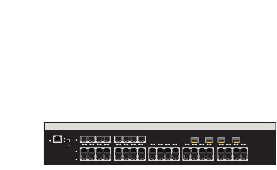
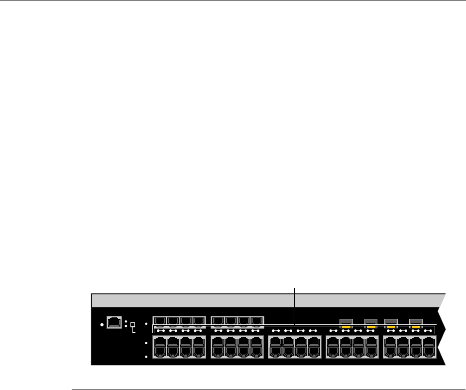
2G4072-52
TheEnterasysMatrixNSA2G4072‐52has48,10/100/1000BASE‐T/‐TXcompliantports,
throughfixedfrontpanelRJ45connectorsand4Mini‐GBICports,asshowninFigure 1‐1.
Eachofthefixedfrontpanelportscanoperateineitherhalf‐duplexorfull‐duplexmode
whichcanbedeterminedbyeitherauto‐negotiationormanualconfiguration.
EnterasysMatrixNSA2G4072‐52portscanbeconfiguredtocontroltrafficbylimitingits
rateandprioritizingittoexpeditehigherpriorityflowsthroughthedevice.
Figure 1-1 2G4072-52 Front Panel
Connectivity
Dependingonhowthe2G4072‐52isconfigured,itcansupportupto48,10BASE‐T/
100BASE‐TXswitchedportsconnectedthroughthefrontpanelconnectors.
Management
Managementofthedevicecanbeeitherin‐bandorout‐of‐band.In‐bandremote
managementispossibleusingTelnet,Enterasys Networks’NetSight®management
application,orWebView™application.Out‐of‐bandmanagementisprovidedthrough
theRJ45COM(Communication)portonthefrontpanelusingaVT100terminalora
VT100terminalemulator.
Switch Configuration Using WebView
Enterasys Networks’HTTP‐basedWebmanagementapplication(WebView)isan
intuitivewebtoolforsimplemanagementtasks.
RESET
CONSOLE
CPU
PWR GROUP
SELECT
GROUP 3
GROUP 2
GROUP 1
1 2 3 4 5 6 7 8 9 10 11 12 13 14 15 16 17 18 19 20
2G4072-52
Standards Compatibility
N Standalone Series Installation Guide 1-3
Switch Configuration Using CLI Commands
CLIcommandsenableyoutoperformmorecompleteswitchconfigurationmanagement
tasks.ForCLIcommandsetinformationandhowtoconfigurethedevice,refertothe
EnterasysMatrixNStandaloneSeriesConfigurationGuide.
Standards Compatibility
TheEnterasysMatrixNSA2G4072‐52isfullycompliantwiththeIEEE802.3‐2002,
802.3ae‐2002,802.1D‐1998,and802.1Q‐1998standards.ItprovidesIEEE802.1D‐1998
SpanningTreeAlgorithm(STA)supporttoenhancetheoverallreliabilityofthenetwork
andprotectagainst“looping”conditions.
LANVIEW Diagnostic LEDs
LANVIEWdiagnosticLEDs,asshowninFigure 1‐2,serveasanimportant
troubleshootingaidbyprovidinganeasywaytoobservethestatusofindividualports
andoverallnetworkoperations.
Figure 1-2 LANVIEW LEDs
1LANVIEW LEDs
RESET
CONSOLE
CPU
PWR GROUP
SELECT
GROUP 3
GROUP 2
GROUP 1
À
1 2 3 4 5 6 7 8 9 10 11 12 13 14 15 16 17 18 19 20

LANVIEW Diagnostic LEDs
1-4 Introduction
N Standalone Series Installation Guide 2-1
2
Network Requirements
Beforeinstallingthemodule,reviewtherequirementsandspecificationsreferredtoin
thischapterconcerningthefollowing:
Thenetworkinstallationmustmeettherequirementstoensuresatisfactoryperformance
ofthisequipment.Failuretodosowillproducepoornetworkperformance.
Link Aggregation
LinkAggregationisamethodofgroupingmultiplephysicalportsonanetworkdevice
intoonelogicallinkaccordingtotheIEEE802.3ad‐2002standard.BecauseLink
Aggregationisstandardsbased,itpermitsautomaticconfigurationwithmanual
overrides(ifapplicable),andcanoperateon10Mbps,100Mbps,or1000MbpsEthernet
fullduplexports.So,youcancombineagroupoffive100Mbpsportsinalogicallink
(trunk)thatfunctionsasasingle500Mbpsport.Aslongasthe2G4072‐52acceptswhich
portsareinthetrunk,therearenoproblemswithlooping,andtheSpanningTreecantreat
thistrunkasasingleport.
Innormalusage(andtypicalimplementations)thereisnoneedtoenable/disableportsfor
LinkAggregation.Thedefaultvalueswillresultinthemaximumnumberofaggregations
possible.Iftheswitchisplacedinaconfigurationwithitspeersnotrunningtheprotocol,
noaggregationswillbeformedandthe2G4072‐52willfunctionnormally(thatis,
SpanningTreewillblockredundantpaths).
For information about... Refer to page...
Link Aggregation 2-1
10BASE-T Network 2-2
100BASE-TX Network 2-2
1000BASE-SX/SX+/LX Network 2-2
1000BASE-T Network 2-2
Note: The Enterasys Matrix N Standalone Series Configuration Guide and the Cabling
Guide referred to in the following sections can be found on the Enterasys Networks World
Wide Web site: http://www.enterasys.com/

10BASE-T Network
2-2 Network Requirements
FordetailsaboutthecommandsinvolvedwithconfiguringtheLinkAggregation
function,refertotheEnterasysMatrixNStandaloneSeriesConfigurationGuide.
10BASE-T Network
Whenconnectinga10BASE‐TsegmenttoanyRJ45frontpanelportsofthe2G4072‐52,
ensurethatthenetworkmeetstheEthernetnetworkrequirementsoftheIEEE802.3‐2002
standardfor10BASE‐T.RefertotheCablingGuidefordetails.
100BASE-TX Network
TheRJ45frontpanelportsprovideaconnectionthatsupportsCategory5UTPcabling.
ThedeviceattheotherendofthetwistedpairsegmentmustmeetIEEE802.3‐2002
100BASE‐TXFastEthernetnetworkrequirementsforthedevicestooperateat100 Mbps.
RefertotheCablingGuidefordetails.
1000BASE-SX/SX+/LX Network
ThefourMini‐GBICsprovideGigabitEthernetfiber‐opticconnectionsoperatingat
1000 Mbps(1 Gbps).OtherMini‐GBICsmaysupportdifferenttypesofcabling
connections.Thedeviceattheotherendofthefiber‐opticconnectionmustmeetIEEE
802.3‐2002GigabitEthernetrequirementsforthedevicestooperateatGigabitspeed.
RefertoAppendix AforMini‐GBICspecifications.
1000BASE-T Network
The2G4072‐52’s48portssupport10/100/1000 MbpsthroughRJ45frontpanelconnectors.
Theselinksaccommodatecopperwireconnectionsthatcanoperateupto1000 Mbps.The
deviceattheotherendofthetwistedpairsegmentmustmeetIEEE802.3‐2002
10/100/1000BASE‐TnetworkrequirementsforthedevicestooperateatGigabitspeed.
Note: If a port operates at 100 Mbps, Category 5 cabling must be used. Category 3
cabling does not meet 100 Mbps specifications. For 10 Mbps operations only, Category 3
or Category 5 cabling can be used.
Note: The RJ45 ports support Category 5 UTP cabling with an impedance between 85
and 111 ohms for 100 Mbps operation.
The 2G4072-52 is capable of operating at either 10 or 100 Mbps. It automatically senses
the speed of the connected device and adjusts its speed accordingly.
Note: The 48 ports of the device support Category 5 UTP cabling with an impedance
between 85 and 111 ohms for 100 and 1000 Mbps operation.
Ports 1 through 48 can operate at either 10, 100, or 1000 Mbps. The device automatically
senses the speed of the connected device and adjusts its speed accordingly.

N Standalone Series Installation Guide 3-1
3
Installation
Thischapterprovidestheinstructionstoinstallthe2G4072‐52.
APhillipsscrewdriverisrequiredonlytoattachtwooptionalrack‐mountingbracketson
the2G4072‐52.Followtheorderofthesectionslistedbelowforcorrectinstallation:
Unpacking the 2G4072-52
Unpackthe2G4072‐52asfollows:
1. OpentheboxandremovethepackingmaterialprotectingtheEnterasysMatrixNSA
2G4072‐52.
2. Opentheaccessorykitandremovethepowercord,rack‐mountears,screws,DB9to
RJ45converter,andadhesivefeet(fordesk‐topplacement).
3. Verifythecontentsofthecartonaslistedinthetablebelow.
For information about... Refer to page...
Unpacking the 2G4072-52 3-1
Rack Mounting 3-2
Connecting Power 3-4
Connecting to the Network 3-5
Connecting to the COM Port for Local Management 3-13
Completing the Installation 3-18
Important Notice
Read the Release Notes shipped with the 2G4072-52 to check for any exceptions to the
supported features and operation documented in this guide.
Rack Mounting
3-2 Installation
4. InspecttheEnterasysMatrixNSA2G4072‐52foranysignsofphysicaldamage.
ContactEnterasys Networksifitisdamaged.Referto“GettingHelp”onpage xviii
fordetails.
Rack Mounting
Theinstallationsitemustbewithinreachofthenetworkcablingandmeetthe
requirementslistedbelow:
• Appropriategroundedpowerreceptaclesmustbelocatedwithin7feetofthesite.
•Atemperatureofbetween5°C(41°F)and40°C(104°F)mustbemaintainedatthe
installationsitewithfluctuationsoflessthan10°C(18°F)perhour.
TheEnterasysMatrixNSA2G4072‐52canbemountedinastandard19‐inchrackwiththe
twoearsprovidedinthecarton.Theprocedureisasfollows:
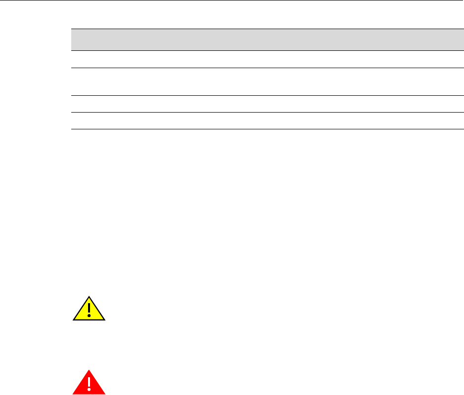
1. WithfourofthesuppliedM4x6mmflatheadscrews,attachaneartothesideofthe
EnterasysMatrixNSA2G4072‐52asshowninFigure 3‐1.Repeattheprocedurefor
theotherear.
Table 3-1 Contents of 2G4072-52
Item
Matrix N Standalone Series 2G4072-52
Accessory Kit including: power cord, rack-mount ears, eight M4 x 6 mm flathead screws, DB9 to
RJ45 converter, and adhesive feet
Installation Guide
Release Notes
Caution: To ensure proper ventilation and prevent overheating, leave a minimum
clearance space of 5.1 cm (2.0 in.) at the left, right, and rear of the device.
Precaución: Para asegurar una buena ventilación y evitar que el sistema se
sobrecaliente, deje un espacio mínimo de 5.1 cm (2 pulgadas) con respecto a los lados y
a la parte posterior del aparato.
Warning: Before rack-mounting the device, ensure that the rack can support it without
compromising stability. Otherwise, personal injury and/or equipment damage may result.
Advertencia. Antes de montar el equipo en el rack, asegurarse que el rack puede
soportar su peso sin comprometer su propia estabilidad, de otra forma, daño personal o
del equipo puede ocurrir.
Warnhinweis: Überzeugen Sie sich vor dem Einbau des Gerätes in das Rack von dessen
Stabilität, ansonsten könnten Personenschäden oder Schäden am Gerät die Folge sein.
Rack Mounting
N Standalone Series Installation Guide 3-3
Figure 3-1 Attaching Rack-mount Ears to Enterasys Matrix N SA 2G4072-52
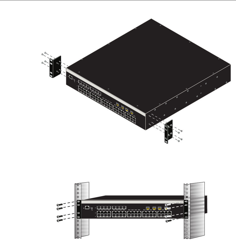
2. PositiontheEnterasysMatrixNSA2G4072‐52intherackandattachtotherackas
showninFigure 3‐2.
Figure 3-2 Mounting Enterasys Matrix N SA 2G4072-52 to Rack
RESET
CONSOLE
CPU
PWRGROUP
SELECT
GROUP 3
GROUP 2
GROUP 1
12345678910 11 1213 14 15 16 17 18 19 20
2G4072-52
2G4052-72
RESET
CONSOLE
CPU
PWR GROUP
SELECT
GROUP 3
GROUP 2
GROUP 1
1 2 3 4 5 6 7 8 9 101112 13141516 17181920
Connecting Power
3-4 Installation
Connecting Power
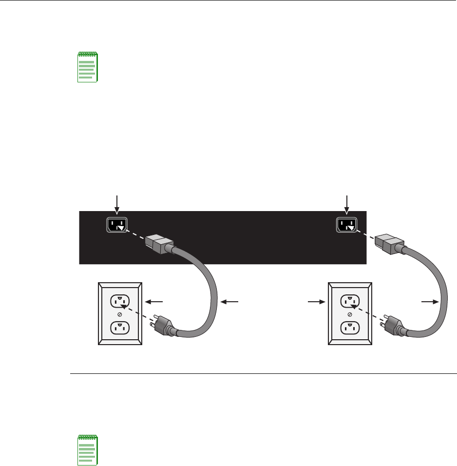
Toconnectthemoduletothepowersources,refertoFigure 3‐3andproceedasfollows.
Toconnectthemoduletothepowersources,refertoFigure 3‐3andproceedasfollows:
1. PlugapowercordintoeachswitchACpowerreceptacle.Totakeadvantageof
redundancycapabilities,plugeachpowercordintoaseparatededicatedACoutlet.
2. PlugthecordintoadedicatedgroundedACoutletasshowninFigure 3‐3.
Figure 3-3 Connecting Power
3. ObservetheLANVIEWLEDs.ThePower(PWR)LED(notshown),locatedonthe
frontpanel,turnsON(green)andtheCPUturnsreduntilthemodulecompletesits
initialization.Ittakesunder30secondsforthemoduletobootup.
Iftheinitializationprocessissuccessful,theCPULEDturnsgreen.IftheCPULEDdoes
notturngreen,refertoChapter 4fortroubleshootinginformation.
Note: The two power supplies in the module have automatic voltage sensing that allows
connection to power sources ranging from 100–125 Vac, 2.5 A or 200–240 Vac, 1.25 A,
50/60 Hz.
1AC power cords 2AC power outlets 3AC power receptacles
Note: If the power-up sequence is interrupted on this device, or if optional hardware has
been installed or removed, this device may run an extended diagnostics sequence that
may take up to two minutes to complete.
AC INLET 1
100 - 125V ~ 3.6A
200 - 240V ~ 1.6A
50/60 Hz
AC INLET 2
100 - 125V ~ 1.8A
200 - 240V ~ 0.8A
50/60 Hz
Á Á
À ÀÂ Â

Connecting to the Network
N Standalone Series Installation Guide 3-5
Connecting to the Network
Thissectionprovidestheproceduresforconnectingunshieldedtwistedpair(UTP)
segmentsfromthenetworkorotherdevicestothe2G4072‐52.ForconnectionstoMini‐
GBICports,refertopage3‐9.
Connecting UTP Cables
ThefixedRJ45frontpanelconnectionsofthe2G4072‐52are10/100/1000Mbpsports.They
haveinternalcrossoversandsupportautomatic‐polaritysensingwhicheliminatesthe
needforacrossovercable,regardlessiftheconnectionistoanothernetworkdeviceora
workstation.
Inthisprocedure,the2G4072‐52isusedastheexampletoconnectatwistedpairsegment
tothedevice,asshowninFigure 3‐4.
1. EnsurethatthedeviceconnectedtotheotherendofthesegmentispoweredON.
2. ConnectthetwistedpairsegmenttothedevicebyinsertingtheRJ45connectoronthe
twistedpairsegmentintotheappropriateRJ45portconnector.
Note: If the Enterasys Matrix N SA 2G4072-52 is being installed in a network using Link
Aggregation, there are rules concerning the network cable and port configurations that
must be followed for Link Aggregation to operate properly. Before connecting the cables,
refer to the Enterasys Matrix N Standalone Series Configuration Guide for the
configuration information. For details on how to obtain manuals, refer to “Related
Documents”onpage xvi.
Note: All RJ45 front panel ports on the 2G4072-52 support Category 5 Unshielded
Twisted Pair (UTP) cabling with an impedance between 85 and 111 ohms. You can use
Category 3 cable only for 10 Mbps connections.
Connecting to the Network
3-6 Installation
Figure 3-4 Connecting a Twisted Pair Segment to the 2G4072-52
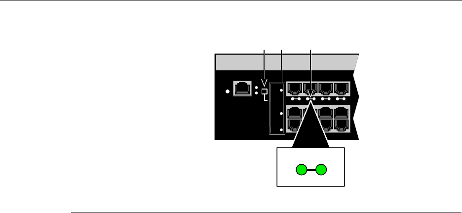
3. VerifythatalinkexistsbycheckingthattheportRX(Receive)LEDisON(flashing
amber,blinkinggreen,orsolidgreen).IftheRXLEDisOFFandtheTX(Transmit)
LEDisnotblinkingamber,performthefollowingstepsuntilitison:
a. Toviewthereceiveandtransmitactivityonagroupofsegments,pressthe
GROUPSELECTbutton(seeFigure 3‐4)tosteptothegroupofinterest(Groups1
through3).Eachtimethebuttonispressed,theGROUPLEDlightsupin
sequence,indicatingtheselectedGroup.Receiveandtransmitactivityforthat
groupofsegmentsisthenindicatedbytheRXandTXLEDsforeachsegment.
b. VerifythatcablingisCategory5UTPwithanimpedancebetween85and
111 ohms.Iftheportistooperateat100 Mbps,Category 5cablingmustbeused.
c. Verifythatthedeviceattheotherendofthetwistedpairsegmentisonand
properlyconnectedtothesegment.
d. VerifythattheRJ45connectorsonthetwistedpairsegmenthavetheproper
pinoutsandcheckthecableforcontinuity.Typically,acrossovercableisused
betweenhubdevices.Astraight‐throughcableisusedtoconnectbetween
switchesorhubdevicesandanenduser(computer).RefertoFigure 3‐5and
Figure 3‐6forfour‐wireRJ45connections.RefertoFigure 3‐7andFigure 3‐8for
eight‐wireRJ45connections.
1RJ45 connector 2RJ45 port connector 3GROUP SELECT button
RESET
CONSOLE
CPU
PWR GROUP
SELECT
GROUP 3
GROUP 2
GROUP 1
1234
À ÂÁ
2
TX
RX
Connecting to the Network
N Standalone Series Installation Guide 3-7
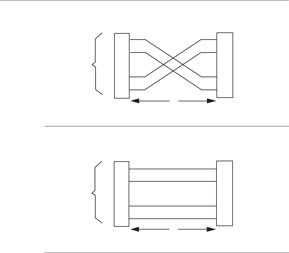
Figure 3-5 Crossover Four-Wire Cable RJ45 Pinouts
Figure 3-6 Straight-Through Four-Wire Cable RJ45 Pinouts
1RJ45 device port 3RJ45-to-RJ45 crossover cable
2Other device port 4RX+/RX- and TX+/TX- connections (must share a common color pair)
1RJ45 device port 3RJ45-to-RJ45 straight-through cable
2Other device port 4RX+/RX- and TX+/TX- connections (must share a common color pair)
TX+
TX
RX+
RX 2
1
3
6
TX+
TX
2
1
3
6
RX+
RX
ÀÁ
Â
Ã
TX+
TX
RX+
RX 2
1
3
6
TX+
TX
2
1
3
6
RX+
RX
ÀÁ
Â
Ã
Connecting to the Network
3-8 Installation
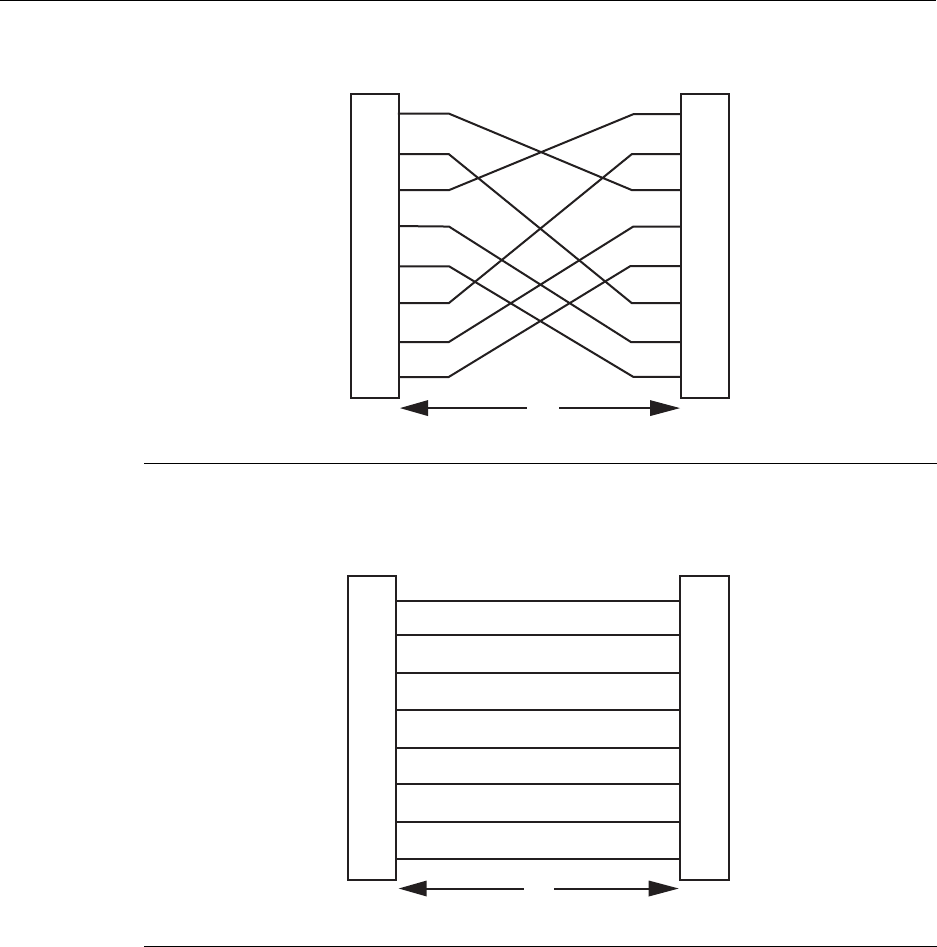
Figure 3-7 Eight-Wire Crossover Cable RJ45 Pinouts
Figure 3-8 Eight-Wire Straight-Through Cable RJ45 Pinouts
1RJ45 device port 2Other device port 3RJ45-to-RJ45 crossover cable
1RJ45 device port 2Other device port 3RJ45-to-RJ45 straight-through cable
2
1
3
6
4
5
7
8
TX1+
TX2+
RX4-
RX1-
TX4+
RX3-
TX3+
RX2-
TX2+
TX1+
RX3-
RX2-
TX3+
RX4-
TX4+
RX1-
2
1
3
6
4
5
7
8
Á
À
Â
TX1+
TX2+
RX4-
RX1-
TX4+
RX3-
TX3+
RX2-
2
1
3
6
4
5
7
8
TX2+
TX1+
RX3-
RX2-
TX3+
RX4-
TX4+
RX1-
2
1
3
6
4
5
7
8
À
Â
Á
Connecting to the Network
N Standalone Series Installation Guide 3-9
e. EnsurethatthetwistedpairconnectionmeetsthedBlossandcablespecifications
outlinedintheCablingGuide.Referto“RelatedDocuments”onpage xvifor
informationonobtainingthisdocument.
Ifalinkisnotestablished,contactEnterasysNetworks.Referto“Troubleshooting”on
page 4‐1fordetails.
4. Repeatsteps1through3above,untilallconnectionshavebeenmade.
Connecting Fiber-Optic Cables to Mini-GBICs
Thissectiondescribesconnecting1‐GigabitEthernetfiber‐opticsegmentsfromthe
networkorotherdevicestoMini‐GBICMT‐RJorLCportconnectorsintheEnterasys
MatrixNSA2G4072‐52.
Eachfiber‐opticlinkconsistsoftwofiber‐opticstrandswithinthecable:Transmit(TX)and
Receive(RX).
Thetransmitstrandfromamoduleportconnectstothereceiveportofafiber‐optic
GigabitEthernetdeviceattheotherendofthesegment.Thereceivestrandofthe
applicableMT‐RJportonthemoduleconnectstothetransmitportofthefiber‐optic
GigabitEthernetdevice(showninFigure 3‐9)orLCcableconnector(showninFigure 3‐10
andFigure 3‐11).
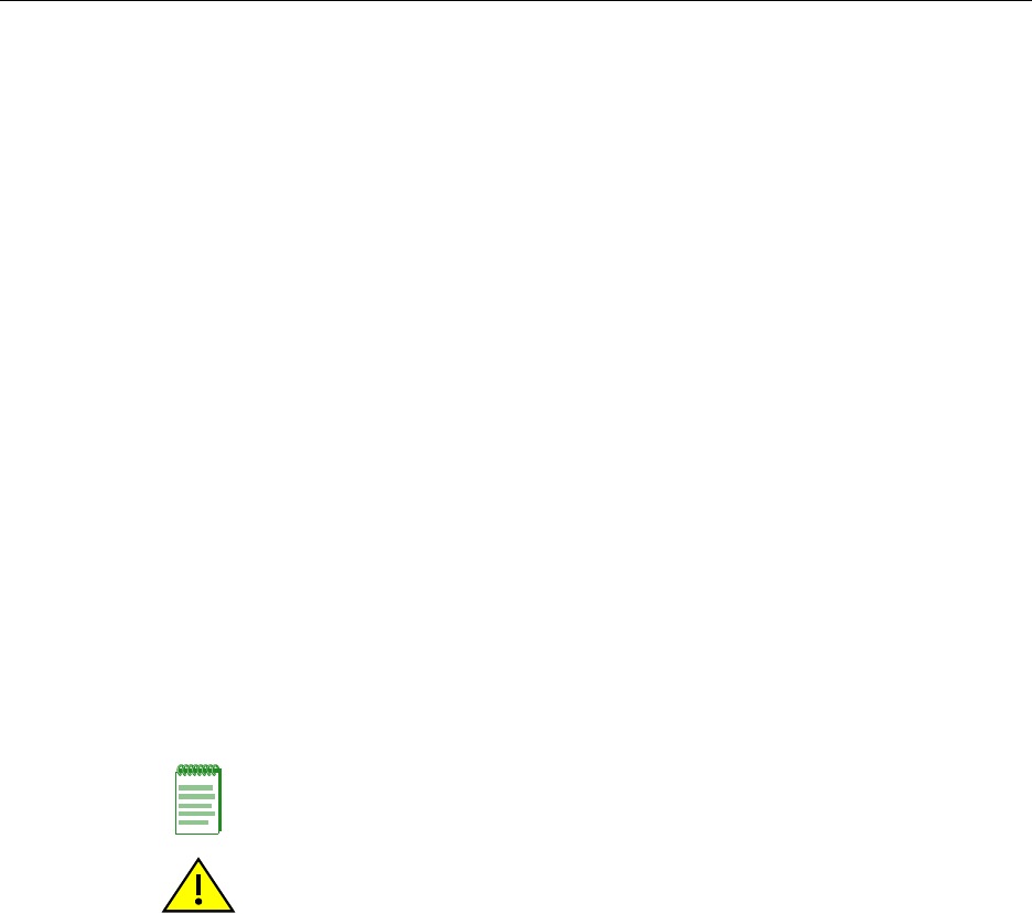
TheprocedurebelowdescribeshowtoconnectanMT‐RJcable(Figure 3‐9)connectortoa
Mini‐GBICportconnector.ThisprocedurealsoappliestoanLCcableconnectorshownin
(Figure 3‐10andFigure 3‐11).RefertoFigure 3‐9asanexampleandproceedasfollows:
1. Removetheprotectivecovers(notshown)fromtheMT‐RJfiber‐opticportonthe
Mini‐GBICandfromtheconnectorsoneachendofthecable.
Note: Leave the protective covers in place when the connectors are not in use to prevent
contamination.
Caution: Do not touch the ends of the fiber-optic strands, and do not let the ends come in
contact with dust, dirt, or other contaminants. Contamination of cable ends causes
problems in data transmissions. If the ends of the fiber-optic strands become
contaminated, use a canned duster to blow the surfaces clean. A cleaning swab saturated
with optical-grade isopropyl alcohol may also be used to clean the ends.
Precaución: No toque los extremos de los cables de fibra óptica y evite su contacto con el
polvo, la suciedad o con cualquier otro contaminante. Si los extremos de los cables se
ensucian, es posible que la transmisión de datos se vea afectada. Si nota que los
extremos de los cables de fibra óptica se ensucian, utilice aire comprimido para limpiarlos.
También puede limpiarlos con un estropajo embebido en alcohol isopropílico.
Connecting to the Network
3-10 Installation
2. InserttheMT‐RJcableconnectorintotheMini‐GBICuntilitclicksintoplace.
Figure 3-9 Cable Connection to MT-RJ Fiber-Optic Connectors
Note: To remove the MT-RJ cable connector, press on its release tab and pull it out of the
Mini-GBIC.
1Mini-GBIC (MGBIC-MT01) 4Port slot
2Mini-GBIC, top side 5Mini-GBIC, protective dust cover
37-Pin edge connector (insertion side) 6Release tab
13 14 15 16 17 18 19 20
Ã
Â
Ä
À
Á
Å
2G4072-52
Connecting to the Network
N Standalone Series Installation Guide 3-11
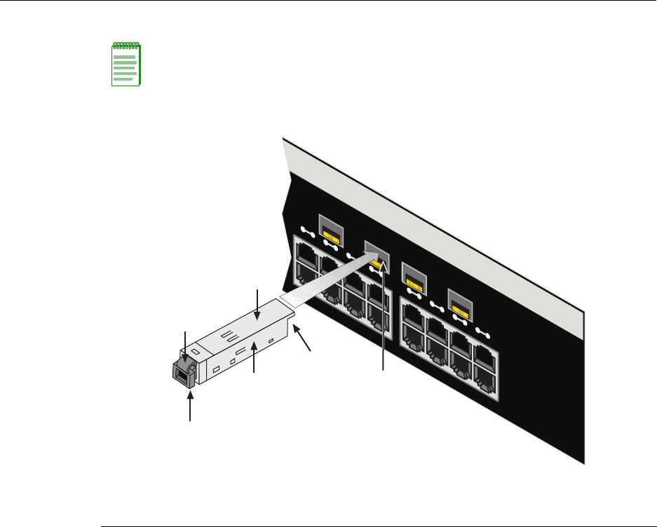
Figure 3-10 Cable Connection to LC01 or LC09 Fiber-Optic Connectors
1Mini-GBIC (MGBIC-LC01 or -LC09) 4Port slot
2Mini-GBIC, top side 5Mini-GBIC, protective dust cover
37-Pin edge connector (insertion side) 6Release tab
2G4072-52
13 14 15 16 17 18 19 20
➃
➂
➅
➀
➁
➄
Connecting to the Network
3-12 Installation
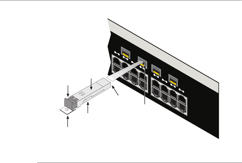
Figure 3-11 Cable Connection to LC03 Fiber-Optic Connectors
3. VerifyalinkexistsbycheckingthattheportRXLEDison(flashingamber,blinking
green,orsolidgreen).IftheRXLEDisoff,performthefollowingstepsuntilitison:
a. VerifythedeviceattheotherendofthesegmentisONandlinkedtothesegment.
b. Ifthereareseparatefiber‐opticconnectionsontheotherdevice,checkthe
crossoverofthecables.Swapthecableconnectionsifnecessary.
c. Checkthatthefiber‐opticconnectionmeetsthedBlossandcablespecifications
outlinedintheCablingGuideformultimodefiber‐opticcabling.Toobtainthis
document,referto“RelatedDocuments”onpage xvi.
Ifalinkhasnotbeenestablished,refertoChapter 4forLEDtroubleshootingdetails.If
aproblempersists,referto“GettingHelp”onpage xviiiforsupport.
4. Repeatsteps1through3,above,untilallconnectionshavebeenmade.
5. Plugtheotherendofthecableintotheappropriateportontheotherdevice.Some
cablesmaybeterminatedattheotherendwithtwoseparateconnectors,oneforeach
fiber‐opticstrand.Inthiscase,ensurethatthetransmitfiber‐opticstrandisconnected
tothereceiveportandthereceivefiber‐opticstrandtothetransmitport.
1Port slot 3Release tab 5Receive LED (TX)
2Mini-GBIC-LC03 cable connector 4Transmit LED (RX)
13 14 15 16 17 18 19 20
Á
2G4072-52
Â
À
Ä
Ã

Connecting to the COM Port for Local Management
N Standalone Series Installation Guide 3-13
Connecting to the COM Port for Local Management
ThissectiondescribeshowtoinstallaUTPcablewithRJ45connectorsandoptional
adapterstoconnectaPC,VTseriesterminal,ormodemtoanEnterasys Networksdevice
toaccessLocalManagement.Thissectionalsodetailsadapterpinoutassignments.
What Is Needed
Thefollowingisalistofthepartsthatmaybeneededdependingontheconnection:
•RJ45‐to‐DB9femaleadapter(suppliedinaccessorykit)
•UTPcablewithRJ45connectors(user‐supplied)
•RJ45‐to‐DB25femaleadapter(user‐supplied)
•RJ45‐to‐DB25maleadapter(user‐supplied)
WithaUTPcablewithRJ45connectorsandRJ45‐to‐DB9adapter,youcanconnect
productsequippedwithanRJ45COMporttoanIBMorcompatiblePCrunningaVT
seriesemulationsoftwarepackage.
WithaUTPcableandanoptionalRJ45‐to‐DB25femaleadapter,youcanconnectproducts
equippedwithanRJ45COMporttoaVTseriesterminalorVTtypeterminalsrunning
emulationprogramsfortheVTseries.
WithaUTPcableandanoptionalRJ45‐to‐DB25maleadapter,youcanconnectproducts
equippedwithanRJ45COMporttoaHayescompatiblemodemthatsupports9600 baud.
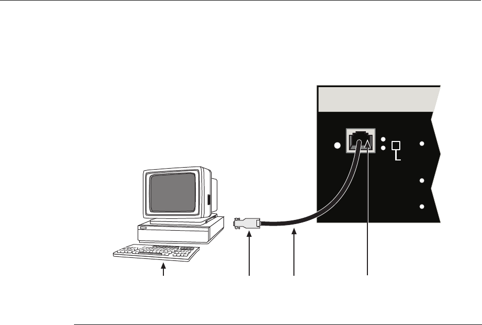
Connecting to an IBM PC or Compatible Device
ToconnectanIBMPCorcompatibledevice,runningtheVTterminalemulation,toan
Enterasys NetworksdeviceCOMport(Figure 3‐12),proceedasfollows:
1. ConnecttheRJ45connectoratoneendofthecabletothecommunicationsCOM
(Console)portontheEnterasys Networksdevice.
2. PlugtheRJ45connectorattheotherendofthecableintoanoptionalRJ45‐to‐DB9
adapter.
3. ConnecttheRJ45‐to‐DB9adaptertothecommunicationsportontheIBMPC.
4. TurnonthePCandconfigureyourVTemulationpackagewiththeseparameters:
Parameter Setting
Mode 7BitControl
Transmit Transmit=9600
BitsParity 8Bits,NoParity
StopBit 1StopBit
Connecting to the COM Port for Local Management
3-14 Installation
5. Whentheseparametersareset,theLocalManagementpasswordscreenwilldisplay.
RefertotheappropriateEnterasysMatrixNStandaloneSeriesConfigurationGuidefor
furtherinformation.
Figure 3-12 Connecting an IBM PC or Compatible
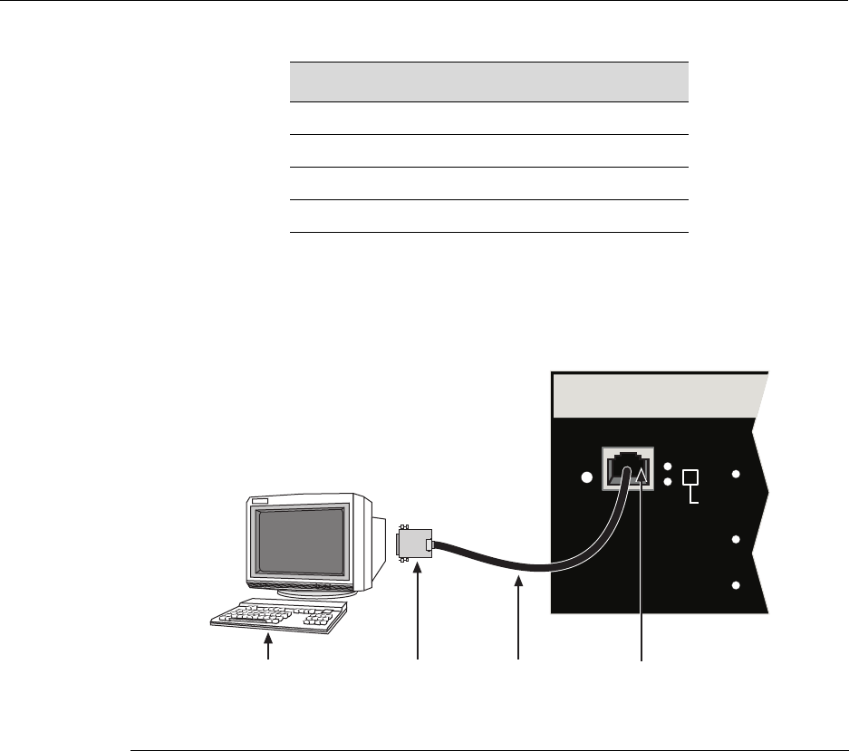
Connecting to a VT Series Terminal
ToconnectaVTSeriesterminaltoaEnterasysMatrixNSA2G4072‐52COMport
(Figure 3‐13),useaUTPcablewithRJ45connectorsandanoptionalRJ45‐to‐DB25female
adapter.Proceedasfollows:
1. ConnecttheRJ45connectoratoneendofthecabletotheCOMportonthe
Enterasys Networksdevice.
2. PlugtheRJ45connectorattheotherendofthecableintotheRJ45‐to‐DB25female
adapter.
3. ConnecttheRJ45‐to‐DB25adaptertotheportlabeledCOMMontheVTterminal.
1UTP cable with RJ45 connectors 3RJ45-to-DB9 PC adapter
2RJ45 COM port 4IBM PC or compatible device
RESET
CONSOLE
CPU
PWR GROUP
SELECT
GROUP 3
GROUP 2
GROUP 1
ÂÃÁ
À
Connecting to the COM Port for Local Management
N Standalone Series Installation Guide 3-15
4. TurnontheterminalandaccesstheSetupDirectory.Setthefollowingparameters:
Whentheseparametersareset,theLocalManagementpasswordscreenwilldisplay.
RefertotheEnterasysMatrixNStandaloneSeriesConfigurationGuideforfurther
information.
Figure 3-13 Connecting a VT Series Terminal
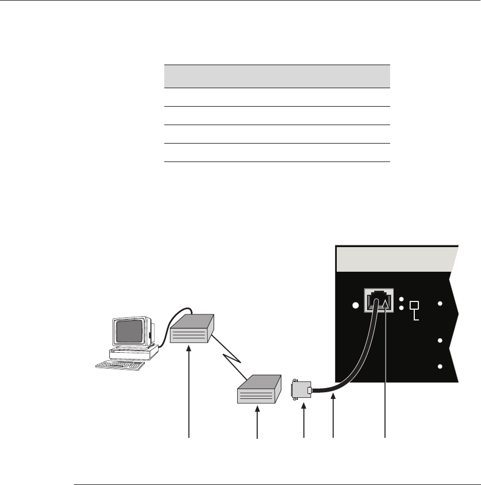
Connecting to a Modem
ToconnectamodemtothedeviceCOMport(Figure 3‐14),useaUTPcablewithRJ45
connectorsandanoptionalRJ45‐to‐DB25maleadapter,andproceedasfollows:
1. ConnecttheRJ45connectoratoneendofthecabletotheCOMportofthemodule.
2. PlugtheRJ45connectorattheothercableendintotheRJ45‐to‐DB25modemadapter.
3. ConnecttheRJ45‐to‐DB25adaptertothecommunicationsportonthemodem.
Parameter Setting
Mode 7BitControl
Transmit Transmit=9600
BitsParity 8Bits,NoParity
StopBit 1StopBit
1UTP cable with RJ45 connectors 3RJ45-to-DB25 VT adapter
2RJ45 COM port 4VT series terminal
RESET
CONSOLE
CPU
PWR GROUP
SELECT
GROUP 3
GROUP 2
GROUP 1
Á
 ÀÃ
Connecting to the COM Port for Local Management
3-16 Installation
4. Turnonthemodem.
5. WithaPCconnectedtoaremotemodem,youcanconfiguretheswitchremotely.To
doso,youmustconfigureyourPCVTemulationpackagewiththeseparameters.
6. Whentheseparametersareset,theLocalManagementpasswordscreenwilldisplay.
RefertotheEnterasysMatrixNStandaloneSeriesConfigurationGuideforfurther
information.
Figure 3-14 Connecting to a Modem
Parameter Setting
Mode 7BitControl
Transmit Transmit=9600
BitsParity 8Bits,NoParity
StopBit 1StopBit
1UTP cable & RJ45 connectors 3RJ45-to-DB25 modem adapter 5Remote modem
2RJ45 COM port 4Local modem
RESET
CONSOLE
CPU
PWR GROUP
SELECT
GROUP 3
GROUP 2
GROUP 1
Á
ÀÄ ÂÃ
Connecting to the COM Port for Local Management
N Standalone Series Installation Guide 3-17
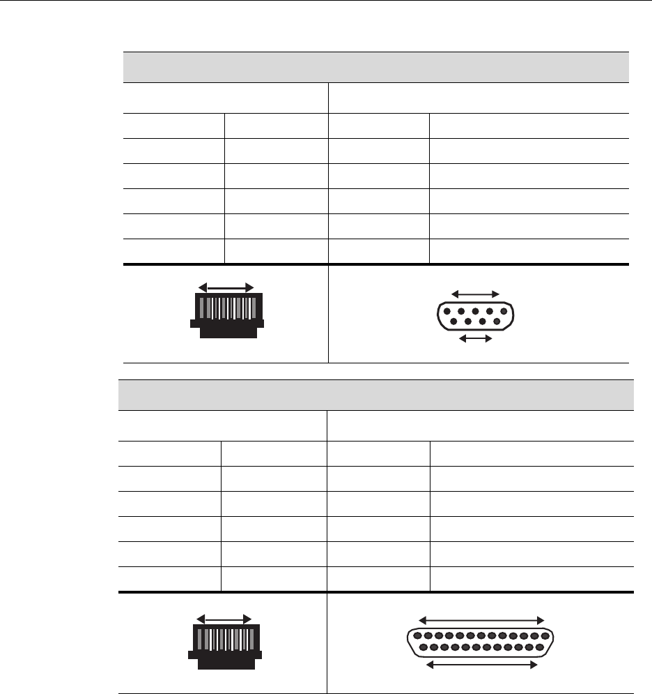
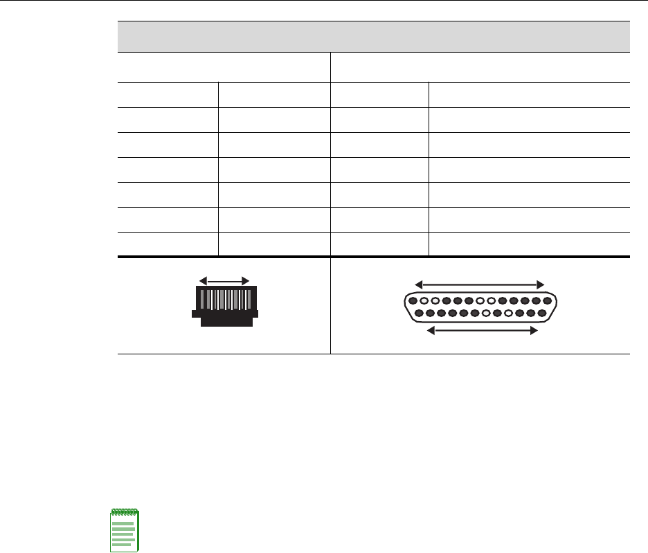
Adapter Wiring and Signal Assignments
COM Port Adapter Wiring and Signal Diagram
RJ45 DB9
Pin Conductor Pin Signal
1Blue2Receive(RX)
4Red3Transmit(TX)
5Green5Ground(GRD)
2Orange7RequesttoSend(RTS)
6 Yellow 8 CleartoSend(CTS)
VT Series Port Adapter Wiring and Signal Diagram
RJ45 DB25
Pin Conductor Pin Signal
4Red2Transmit(TX)
1Blue3Receive(RX)
6Yellow5CleartoSend(CTS)
5 Green7Ground(GRD)
2 Orange 20 DataTerminalReady
RJ45 Connector (Female)
Pins 81
69
DB9 Connector (Female)
15 Pins
RJ45 Connector (Female)
Pins 81
DB25 Connector (Female)
Pins
25 14
13 1
Completing the Installation
3-18 Installation
Completing the Installation
AfterinstallingtheEnterasysMatrixNSA2G4072‐52andmakingtheconnectionstothe
network,accessthedevicemanagementstartupscreenfromyourPC,terminal,ormodem
connectionasdescribedinthefollowingsection.
Log-In Using a Console Port Connection
StarttheCommandLineInterface(CLI)fromthedevice’slocalconsoleportasfollows:
1. Connectaterminaltothelocalconsoleportasdescribedin“ConnectingtotheCOM
PortforLocalManagement”onpage 3‐13.Thestartupscreen,Figure 3‐15,displays.
Modem Port Adapter Wiring and Signal Diagram
RJ45 DB25
Pin Conductor Pin Signal
1Blue2Transmit(TX)
2Orange8DataCarrierDetect(DCD)
4 Red 3 Receive
5 Green7Ground(GRD)
6Yellow20DataTerminalReady(DTR)
8Gray 22 RingIndicator
RJ45 Connector (Female)
Pins 81 Pins
DB25 Connector (Male)
131
2514
Note: This procedure applies only to initial log-in and to logging in to a device not yet
configured with administratively-supplied user and password settings.
By default, the Matrix N Standalone Series device is configured with three user login
accounts: ro for Read-Only access; rw for Read-Write access; and admin for super-user
access to all modifiable parameters. The default password is set to blank (carriage return).
For information on changing these default passwords, refer to Chapter 3 in the Enterasys
Matrix N Standalone Series Configuration Guide.

Completing the Installation
N Standalone Series Installation Guide 3-19
2. Attheloginprompt,enteroneofthefollowingdefaultusernames:
–roforRead‐Onlyaccess,
–rwforRead‐Writeaccess,or
–adminforSuperUseraccess.(ThisaccesslevelallowsRead‐Writeaccesstoall
modifiableparameters,includinguseraccounts.)
3. PressEnter.
4. ThePasswordpromptdisplays.LeavethisstringblankandpressEnter.Thedevice
informationandMatrixpromptdisplaysasshowninFigure 3‐15.
TheEnterasysMatrixNSA2G4072‐52isnowreadytobeconfigured.Forinformation
aboutsettingtheIPaddressandconfiguringTelnetsettingsforremoteaccesstoN
StandaloneSeriesmanagement,refertoChapter3intheEnterasysMatrixNStandalone
SeriesConfigurationGuide.
TheCLIcommandsenableyoutoinitiallysetupandperformmoreinvolved
managementconfigurations.TheEnterasysMatrixNStandaloneSeriesConfigurationGuide
isavailableonlineat:
http://www.enterasys.com/support/manuals

Completing the Installation
3-20 Installation
Figure 3-15 Matrix Startup Screen Example (N7 Chassis)
login: admin
Password:
M A T R I X N7
Command Line Interface
Enterasys Networks, Inc.
50 Minuteman Rd.
Andover, MA 01810-1008 U.S.A.
Phone: +1 978 684 1000
E-mail: support@enterasys.com
WWW: http://www.enterasys.com
(c) Copyright Enterasys Networks, Inc. 2003
Chassis Serial Number: xxxxxxxxxxxx
Chassis Firmware Revision: xx.xx.xx
Matrix N7(su)->

N Standalone Series Installation Guide 4-1
4
Troubleshooting
Thischapterprovidesinformationconcerningthefollowing:
Using LANVIEW
The2G4072‐52usesabuilt‐invisualdiagnosticandstatusmonitoringsystemcalled
LANVIEW.TheLANVIEWLEDs(Figure 4‐1)allowquickobservationofthenetwork
statustoaidindiagnosingnetworkproblems.
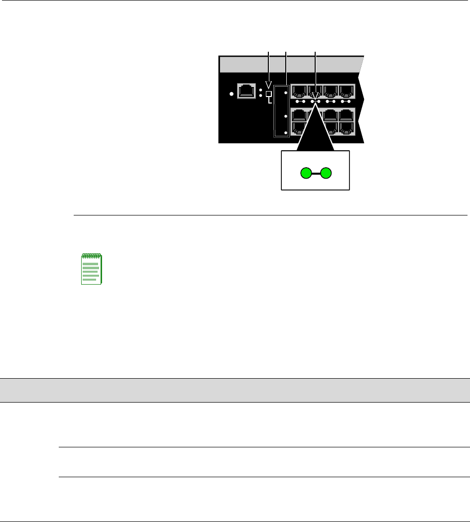
Viewing the Receive and Transmit Activity
Onthe2G4072‐52,youcanviewthereceiveandtransmitactivityontheRXandTXLEDs.
However,onlyonegroupof20portsmaybeviewedatatimeonthe2G4072‐52.
Toviewthereceiveandtransmitactivityonagroupofports,presstheGROUPSELECT
button(seeFigure 4‐1)tosteptothegroupofinterest(Groups1through3).Eachtimethe
GROUPSELECTbuttonispressed,theGROUPLEDlightsupinsequence,indicating
whichgroupisselected.Thereceiveandtransmitactivityforthatgroupofsegmentsis
thenindicatedbytheRXandTXLEDsforeachport.
For information about... Refer to page...
Using LANVIEW 4-1
Troubleshooting Checklist 4-4
Overview of Shutdown Procedure 4-5
Using LANVIEW
4-2 Troubleshooting
Figure 4-1 LANVIEW LEDs
Table 4‐1describestheLEDindicationsandprovidesrecommendedactions.
1Group Select button 2Group LEDs 3LANVIEW LEDs
NOTE: The terms used in Table 4-1 indicate:
Flashing - an LED is flashing randomly.
Blinking - an LED is flashing at a steady rate (approximately 50% on, 50% off).
Solid - a steady LED light. No pulsing.
Alternating - an LED is flashing in a steady rate other than 50% on, 50% off.
RESET
CONSOLE
CPU
PWR GROUP
SELECT
GROUP 3
GROUP 2
GROUP 1
1234
À ÂÁ
2
TX
RX
Table 4-1 LANVIEW LEDs
LED Color State Recommended Action
PWR Off Device not receiving power from power
supply.
Ensure the power cords are plugged in and
there is power at the source.
Contact technical support for help.
Green Functional. Power supply operating
normally.
None.
Amber Indicates loss of power supply
redundancy.
Ensure the power cords are plugged in and
power is available at the source.
Contact technical support for help.

Using LANVIEW
N Standalone Series Installation Guide 4-3
CPU None Power off. Ensure chassis has adequate power.
Amber Blinking. Device in bootup process. None.
Solid. Testing. If the LED remains amber for several minutes,
contact technical support.
Green Blinking. Image starts running. None.
Solid. Functional. None.
Red Solid. Processor in reset. None.
Green
and
Amber
Blinking. Indicates that the 2G4072-52
is in the process of shutting down.
None. This state is activated when the RESET
button is pressed for less than 1 second to
start an orderly shutdown.
Amber
and off
Alternating (67% on, 33% off).
Indicates a shutdown is complete. The
indication will hold for 60 seconds then
automatically restart.
While in this state, you have 60 seconds
before the 2G4072-52 will reboot.
RX
(Receive)
None No link. No activity. Port enabled or
disabled.
None.
Green Solid. Link present, port enabled, no
traffic is being received by the interface.
None.
Amber Flashing. Link present, port enabled,
traffic is being received by the interface.
None.
Red Blinking. Indicates collisions.
(Supported on 10/100 ports only)
Contact technical support.
TX
(Transmit)
None Port enabled, but no activity. If you know the port should be active and is
not, contact technical support.
Green Flashing. Indicates data transmission
activity. Flashing frequency indicates
the data rate.
None.
Red Flashing. Fault or Error (collision). None, unless activity is high in which case
check for network configuration problems or a
defective device.
Table 4-1 LANVIEW LEDs (continued)
LED Color State Recommended Action

Troubleshooting Checklist
4-4 Troubleshooting
Troubleshooting Checklist
Ifthe2G4072‐52isnotworkingproperly,refertoTable 4‐2forachecklistofproblems,
possiblecauses,andrecommendedactionstoresolvetheproblem.
Table 4-2 Troubleshooting Checklist
Problem Possible Cause Recommended Action
All LEDs are
OFF.
Loss of power. Ensure the 2G4072-52 was installed properly according to
the installation instructions in Chapter 3, and that the
chassis has power.
No Local
Management
Password
screen.
Incorrect terminal setup. Refer to the Enterasys Matrix N Standalone Series
Configuration Guide for proper setup procedures.
Improper console cable pinouts. Refer to Appendix A for proper COM port pinouts.
Corrupt firmware image or
hardware fault.
If possible, attempt to download the image to the
2G4072-52 again. Refer to Appendix B for instructions to
clear NVRAM.
Cannot navigate
beyond
Password
screen.
Improper username/ password
combination entered.
If the username/password combination has been forgotten,
refer to Appendix B for instructions on how to set the mode
switch to reset the username/password combination to the
default values.
Cannot contact
the 2G4072-52
through in-band
management.
IP address not assigned. Refer to the Enterasys Matrix N Standalone Series
Configuration Guide for the IP address assignment
procedure.
Port is disabled. Enable port. See Enterasys Matrix N Standalone Series
Configuration Guide for instructions to enable/disable
ports.
Host Port policy and/or
management VLAN is incorrectly
configured, or not configured.
Verify that a management VLAN exists and that it is
associated with the Host Port.
Refer to the Enterasys Matrix N Standalone Series
Configuration Guide for information about Host Port and
management VLAN configuration.
No link to device. Verify that all network connections between the network
management station and the 2G4072-52 are valid and
operating.
If the problem continues, contact Enterasys Networks for
technical support.

Overview of Shutdown Procedure
N Standalone Series Installation Guide 4-5
Overview of Shutdown Procedure
Youcanshutdowna2G4072‐52inanoperatingsystemusingtheRESETbuttonshownin
Figure 4‐2.Therearetwoprocedurestoshutdowna2G4072‐52:
• Recommendedshutdownprocedure(page4‐6)
• Lastresortshutdownprocedure (notrecommended) (page4‐6)
Port(s) goes into
standby for no
apparent reason.
Loop condition detected. Verify that Spanning Tree is enabled. Refer to the
Enterasys Matrix N Standalone Series Configuration Guide
for the instructions to set the type of STA.
Review the network design and delete loops.
If the problem continues, contact technical support.
User parameters
(IP address,
device and
device name,
etc.) were lost
when the
2G4072-52
power was
cycled, the
RESET button
was pressed.
Position of Mode switch (7),
Persistent Data Reset, was
changed sometime before either
cycling power or pressing the
RESET button, causing the user-
entered parameters to reset to
factory default settings.
Clear Persistent Data that was
set through Local Management.
Reenter the lost parameters as necessary. Refer to the
Enterasys Matrix N Standalone Series Configuration Guide
for the instructions to configure the device.
If the problem persists, contact Enterasys Networks for
technical support.
Table 4-2 Troubleshooting Checklist (continued)
Problem Possible Cause Recommended Action
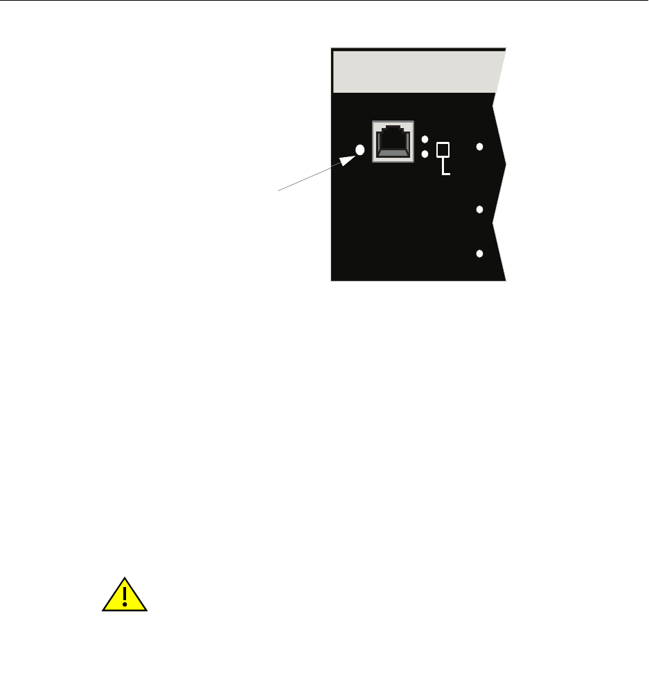
Overview of Shutdown Procedure
4-6 Troubleshooting
Figure 4-2 RESET Button
Recommended Shutdown Procedure Using RESET Button
Beforeshuttingoffpowertoa2G4072‐52,
pressortaponitsRESETbuttonforlessthan1second.
ItsCPULEDchangesfromsolidgreentoblinkingbetweengreenandamber,indicating
thatthe2G4072‐52isshuttingdown.Attheendoftheshutdownroutine,theCPULED
changestoa67%/33%sequenceofamber/off,respectively,indicatingthesystemisina
haltstate.Atthistimeitissafetorestartthe2G4072‐52.
WhenyouinitiateacontrolledshutdownwiththeRESETbutton,youhave60seconds
fromthetimetheCPUstartsflashingamber/offuntilthedeviceautomaticallyrestarts.
Last Resort Shutdown Procedure Using RESET Button
Toreseta2G4072‐52withoutitperforminganorderlyshutdownroutine,
pressandholdthe RESETbuttonforapproximately6seconds.
RESET
CONSOLE
CPU
PWR GROUP
SELECT
GROUP 3
GROUP 2
GROUP 1
Reset button
Caution: This method of shutting down a Enterasys Matrix N SA 2G4072-52 is not
recommended except as a last resort, because all processes currently running on the
module will be interrupted resulting in loss of frames.
Precaución: No se recomienda utilizar este método para apagar los módulos Enterasys
Matrix N SA 2G4072-52. Recurra a él sólo como último recurso, puesto que interrumpe
todos los procesos del módulo en funcionamiento, lo que podría resultar pérdidas de
frames.

N Standalone Series Installation Guide A-1
A
Specifications
Thisappendixprovidesthefollowinginformation:
Enterasys Networksreservestherighttochangespecificationsatanytimewithoutnotice.
2G4072-52 Specifications
Table A‐1describesI/Oports,processorsandmemory,physical,andenvironmental
specificationsforthe2G4072‐52.
For information about... Refer to page...
2G4072-52 Specifications A-1
Mini-GBIC Input/Output Specifications A-2
Gigabit Ethernet Specifications A-3
COM Port Pinout Assignments A-6
Regulatory Compliance A-3
Table A-1 Specifications
Item Specification
2G4072-52 Ports
Ports 1 through 48 48, 10BASE-T/100BASE-TX compliant ports via RJ45
connectors.
Mini-GBIC Ports 4 Mini-GBIC slots for mix-and-match 1000BASE-SX,
SX+ and LX compliant Mini-GBICs. See page A-2 for
supported Mini-GBICs.

Mini-GBIC Input/Output Specifications
A-2 Specifications
Mini-GBIC Input/Output Specifications
Mini‐GigabitEthernetportinterfacesaccept1000BASE‐SXshortwavelengthor
1000BASE‐LXlongwavelengthfiberMini‐GBICs(seeTable A‐2)andarehotswappable.
Processors/Memory
Processor MPC750CX, 400 MHz processor
Dynamic Random Access Memory 256 MB
FLASH Memory 32 MB
Physical
Dimensions 46.43 H x 6.05 W x 29.51 D (cm)
18.28 H x 2.38 W x 11.62 D (in.)
Approximate Weight Gross: 11.79 kg (26 lb)
Mean Time Between Failure (MTBF) Refer to the MTBF web site at URL
http://www.enterasys.com/support/mtbf/
Environmental
Operating Temperature 5°C to 40°C (41°F to 104°F)
Storage Temperature -30°C to 73°C (-22°F to 164°F)
Operating Relative Humidity 5% to 95% (non-condensing)
Table A-1 Specifications (continued)
Item Specification
Table A-2 Mini-GBIC Input/Output Port Specifications
Item Specification
MGBIC-LC01 Provides one LC fiber-optic multimode port that is compliant with the
1000BASE-SX standard LC connector.
MGBIC-LC03 Provides one LC fiber-optic multimode port that is compliant with the
1000BASE-SX standard LC duplex style connector.
MGBIC-LC09 Provides one LC fiber-optic single-mode port that is compliant with the
1000BASE-LX standard LC connector.
MGBIC-MT01 Provides one MT-RJ fiber-optic multi-mode port that is compliant with
the 1000BASE-SX standard MT-RJ connector.
MGBIC-08 Provides one LC fiber-optic single-mode port that is compliant with the
1000BASE-ELX standard LC connector.
MGBIC-02 Provides one RJ45 copper connection that is compliant with the
1000BASE-T standard RJ45 connector.

Gigabit Ethernet Specifications
N Standalone Series Installation Guide A-3
Gigabit Ethernet Specifications
ThefollowingspecificationsfortheMini‐GBICs(showninTable A‐1throughTable A‐6)
meetorexceedtheIEEE802.3z‐1998standard.
MGBIC-LC01 / MGBIC-MT01 Specifications (1000BASE-SX)
MGBIC-LC03 Specifications (1000BASE-SX)
Table A-1 MGBIC-LC01 / MGBIC-MT01 Optical Specifications
Item 62.5 µm MMF 50 µm MMF
Transmit Power (minimum) -9.5 dBm -9.5 dBm
Receive Sensitivity -17 dBm -17 dBm
Link Power Budget 7.5 dBm 7.5 dBm
Table A-2 MGBIC-LC01 / MGBIC-MT01 Operating Range
Item Modal Bandwidth @
850 nm Range
62.5 µm MMF 160 MHz/km 2-220 Meters
62.5 µm MMF 200 MHz/km 2-275 Meters
50 µm MMF 400 MHz/km 2-500 Meters
50 µm MMF 500 MHz/km 2-550 Meters
Table A-3 MGBIC-LC03 Optical Specifications
Item 62.5/125 µm MMF 50/125 µm MMF
Transmit Power (minimum) -9.5 dBm -9.5 dBm
Transmit Power (maximum) -3 dBm -3 dBm
Receive Sensitivity -20 dBm -20 dBm
Link Power Budget1
(Multimode Only)
1. The maximum drive distance (up to 2 km) depends on the quality of the installed multimode fiber-
optic cable segment. Use the Link Power Budget to calculate the maximum cable length of the
attached segment. The Link Power Budget must not exceed those specified in this table. The
MGBIC-LC03 input power must not exceed -3 dBm. Otherwise, saturation could occur.
10.5 dBm 10.5 dBm

Gigabit Ethernet Specifications
A-4 Specifications
MGBIC-LC09 Specifications (1000BASE-LX)
Table A-4 MGBIC-LC03 Operating Range
Item Modal Bandwidth @
1310 nm Range
62.5 µm MMF 160 MHz/km 2,000 Meters
50 µm MMF 400 MHz/km 2,000 Meters
Table A-5 MGBIC-LC09 Optical Specifications
Item 62.5 µm MMF 50 µm MMF 10 µm MMF
Transmit Power (minimum) -11.5 dBm -11.5 dBm -9.5 dBm
Receive Sensitivity -20 dBm -20 dBm -20 dBm
Link Power Budget 8.5 dBm 8.5 dBm 10.5 dBm
Table A-6 MGBIC-LC09 Operating Range
Item Modal Bandwidth @
1300 nm Range
62.5 µm MMF 500 MHz/km 2-550 Meters
50 µm MMF 400 MHz/km 2-550 Meters
50 µm MMF 500 MHz/km 2-550 Meters
10 µm SMF N/A 2-10,000 Meters

Gigabit Ethernet Specifications
N Standalone Series Installation Guide A-5
MGBIC-08 Specifications (1000BASE-ELX)
MGBIC-02 Specifications (1000BASE-T)
Table A-7 MGBIC-08 Optical Specifications
Item
Transmit Power (minimum) -0 dBm, min. +2 dBm, typical +5 dBm, max.
Receive Sensitivity -24 dBm, min. -26 dBm, typical
Maximum Input Power -3 dBm
Link Power Budget1
(Full Duplex Only)
1. The maximum drive distance (up to 70 km) depends on the quality of the installed single-mode fiber-
optic cable segment. Use the Link Power Budget to calculate the maximum cable length of the
attached segment. The Link Power Budget must not exceed those specified in this table. The
MGBIC-08 input power must not exceed -3 dBm. Otherwise, saturation could occur.
23 dB 28 dB, typical
Table A-8 MGBIC-08 Operating Range
Item 1550 nm Range
9 or 10 µm SMF N/A 70,000 Meters
Table A-9 MGBIC-02 Specifications
Item Specification
Supported Cable
Type:
Maximum Length
Copper, Category 5 UTP
Up to 100 meters
Connector RJ45
Data Rate 1 Gbps, IEEE 802.3:2000 compatible
1000BASE-T operation only
Automatic crossover detection
TX Output impedance 100 ohms, typical at all frequencies between 1 MHz and
125 MHz
RX Input impedance 100 ohms, typical at all frequencies between 1 MHz and
125 Hz

COM Port Pinout Assignments
A-6 Specifications
COM Port Pinout Assignments
TheCOMportisaserialcommunicationsportforlocalaccesstolocalmanagement.Refer
tothetablebelowfortheCOMportpinassignments.
Regulatory Compliance
The2G4072‐52meetsthesafetyandelectromagneticcompatibility(EMC)requirements
listedinthetablebelow:
Table A-3 COM Port Pin Assignments
Pin Signal Name Input/Output
1 Transmit Data (XMT) Output
2 Data Carrier Detect (DCD) Output
3 Data Set Ready (DSR) Input
4 Receive Data (RCV) Input
5 Signal Ground (GND) NA
6 Data Terminal Ready (DTR) Output
7 Request to Send (RTS) Input
8 Clear to Send (CTS) NA
Table A-4 Compliance Standards
Regulatory Compliance Standards
Safety UL60950,CSAC22.2No.60950,2006/95/EC,EN60950,IEC60950,
EN 60825,21 CFR 1040.10.
EMC 47 CFR Parts 2 and 15, CSA C108.8, 2004/108/EC, EN 55022, EN
61000-3-2, EN 61000-3-3, EN 55024, AS/NZS CISPR 22,
VCCI V-3.
N Standalone Series Installation Guide B-1
B
Mode Switch Bank Settings
and Optional Installations
Thisappendixcoversthefollowingitems:
Electrical Hazard: Only qualified personnel should perform installation procedures.
Riesgo Eléctrico: Solamente personal calificado debe realizar procedimientos de
instalacion.
Elektrischer Gefahrenhinweis: Installationen sollten nur durch ausgebildetes und
qualifiziertes Personal vorgenommen werden.
For information about... Refer to page...
RequiredTools B-2
SettingtheModeSwitches B-2
MemoryLocationsandReplacementProcedures B-2
Electrical Hazard: Do not remove the cover from the 2G4072-52 while power is applied to
the unit. Hazardous voltages are present and could cause personal injury and/or damage
the unit.
Do not power up the 2G4072-52 again until the cover and screws are in place.
Riesgo Eléctrico: No debe de remover la tapa durente que este coneltado a la corriente,
una descarga electrica le puede causar y probocarle daños, al igual que al aparato.
No enchufe a la corriente hasta que la tapa y los tornillos esten en su lugar.
Elektrischer Gefahrenhinweis: Entfernen sie nicht den Deckel des C, wenn dieser noch
an die Stromzufuhr angeschossen ist, gefährliche Spannungen können Personen
verletzten oder das Gerät beschädigen.
Schalten Sie den 2G4072-52 nicht ein, bevor der Deckel das Gerät abdeckt und mit den
Schrauben fixiert wurde.

Required Tools
B-2 Mode Switch Bank Settings and Optional Installations
Required Tools
Usethefollowingtoolstoperformtheproceduresprovidedinthisappendix:
•Antistaticwriststrap
• Phillipsscrewdriver
Setting the Mode Switches
Figure B‐1showsthelocationsofthemodeswitchesandtheswitchsettingsfornormal
operation.Theseswitchesaresetatthefactoryandrarelyneedtobechanged.
Switchdefinitionsandpositionsareasfollows:
•Switches1through6–ForEnterasys Networksuseonly.
•Switch7–ClearPersistentData.ChangingthepositionofthisswitchclearsPersistent
Dataonthenextpower‐upofthemodule.Alluser‐enteredparameters,suchastheIP
address,modulenames,etc.,areresettothefactorydefaultsettings.Oncethemodule
resets,youcaneitherusethefactorydefaultsettingsorreenteryourownparameters.
Warning: This unit may have more than one power supply cord. Disconnect two power
supply cords before servicing to avoid electric shock.
Advertencia: Esta unida puede tener mas de un cable de fuente de poder. Desconectar
dos cables de fuentes de poder antes de dar servicio para prevenir riesgo eléctrico.
Warnhinweis: Dieses Gerät hat mehrere Netzanschlüße, trennen Sie vor den
Wartungsarbeiten beide Netzanschlüsse vom Versorgungsnetz. zum Schutz vor
elektrischen Schlägen.
Caution: An antistatic wrist strap is required to perform the procedures in this appendix.
Use the antistatic wrist strap to minimize ESD damage to the devices involved.
Precaución: Para llevar a cabo los procedimientos especificados en el apéndice deberá
utilizar una pulsera antiestática. Esta pulsera sirve para minimizar los efectos de las
descargas de electricidad estática.
Caution: Read the appropriate sections to be fully aware of the consequences when
changing switch settings.
Only qualified personnel should change switch settings.
Precaución: Si desea modificar la configuración del interruptor, lea las secciones
correspondientes para saber cuál será el resultado de hacerlo.
Estas modificaciones a la configuración sólo debe realizarlas personal calificado.
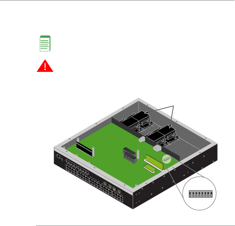
Setting the Mode Switches
N Standalone Series Installation Guide B-3
•Switch8–ClearAdminPassword.Changingthepositionofthisswitchclearsthe
adminpassword,andrestoresthefactorydefaultpasswordonthenextpower‐upof
themodule.Oncethemoduleresets,youcaneitherusethefactorydefaultsettingsor
reenteryourownpassword.
Figure B-1 Mode Switch Location
Note: Do not change the position of Switch 8 unless it is necessary to reset the admin
password to its factory default setting.
Warning: Do not remove safety cover protecting the power supplies.
Advertencia: No quitar tapa de seguridad que protege las fuentes de poder.
Warnhinweis: Entfernen sie keinesfalls das Schutzgehäuse der Stromversorgung.
1Mode switch bank 2Safety cover
RESET
CONSOLE
CPU
PWRGROUP
SELECT
GROUP 3
GROUP 2
GROUP 1
12345678910 11 12 13 14 15 16 17 18 19 20
12345678
ON
À
Á
2G4072-52
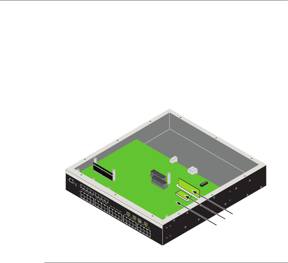
Memory Locations and Replacement Procedures
B-4 Mode Switch Bank Settings and Optional Installations
Memory Locations and Replacement Procedures
IntheeventthattheDualinLineMemoryModule(DIMM)orDRAMSingleIn‐line
MemoryModule(SIMM)(FLASHmemory)needstobereplaced,thefollowingsections
describehowtoaccess,locateandreplacethesememorymodules.Ifyouhavequestions
concerningthereplacementofeithermemorymodule,contactEnterasys Networks.
Location of DIMM and DRAM SIMM Memory Modules
Figure B‐2showsthelocationsoftheDIMMandDRAMSIMMonthemotherboard.
Figure B-2 DIMM and DRAM SIMM Locations
1Motherboard 2DIMM 3DRAM SIMM
RESET
CONSOLE
CPU
PWRGROUP
SELECT
GROUP 3
GROUP 2
GROUP 1
12345678910 11 12 13 14 15 16 17 18 19 20
À
Á
Â
2G4072-52
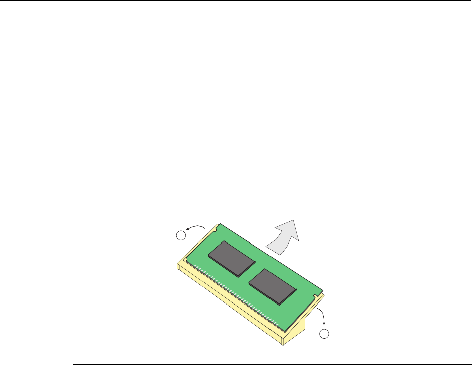
Memory Locations and Replacement Procedures
N Standalone Series Installation Guide B-5
DIMM Replacement Procedure
IftheDIMMisdefectiveandmustbereplaced,thefollowingsectionsexplainhowto
removeandinstalltheDIMM.Ifyouhavequestionsconcerningthereplacementofthe
DIMM,contactEnterasys Networks.
Removing the DIMM
ToremovetheexistingDIMM,proceedasfollows:
1. Followsteps1through3asinstructedon(pageB‐7).
2. LocatetheDIMMconnectoronthemotherboardasshowninFigure B‐2.
3. PushtheconnectorarmsawayfromtheDIMM,asshowninFigure B‐3,and
simultaneouslylifttheDIMMenoughtoreleaseitfromtheconnectorfingers.
Figure B-3 Removing the Existing DIMM
4. RotatetheDRAMSIMMupwards,thenremoveitfromtheconnectorfingers.
1Connector arms 2DIMM 3 Connector fingers
Á
3835_00_14
1
1
Â
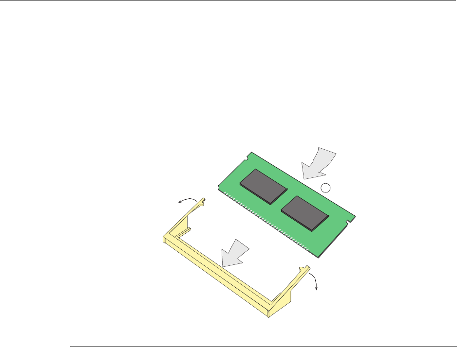
Memory Locations and Replacement Procedures
B-6 Mode Switch Bank Settings and Optional Installations
Installing the DIMM
ToinstallaDIMM,refertoFigure B‐4andproceedasfollows:
1. InserttheDIMMdownbetweentheconnectorfingers.
2. PivottheDIMMdownwardsothetabsontheconnectorarmsalignwiththetwo
DIMMalignmentnotches.Withthetwoconnectorarmsspreadoutward,pushthe
DIMMdownbetweentheconnectorarms.Thenreleasethetwoconnectorarmsto
locktheDIMMintoplace.
Figure B-4 Installing the DIMM
3. Replacethechassiscoverbyre‐attachingtheprovidedscrews.
1DIMM 3Connector arms
2Connector fingers 4SIMM alignment notches (2)
1
3535_01_15
Â
Á
Ã
Ã
Â
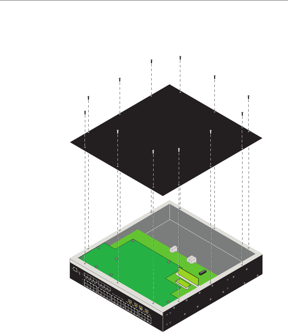
Memory Locations and Replacement Procedures
N Standalone Series Installation Guide B-7
Removing the DRAM SIMM
1. Placethe2G4072‐52onaclean,static‐freesurface.
2. Removethe12screwssecuringthechassiscover,asshowninFigure B‐5.
Figure B-5 Removing Chassis Cover
RESET
CONSOLE
CPU
PWRGROUP
SELECT
GROUP 3
GROUP 2
GROUP 1
1234567891011121314151617181920
2G4072-52
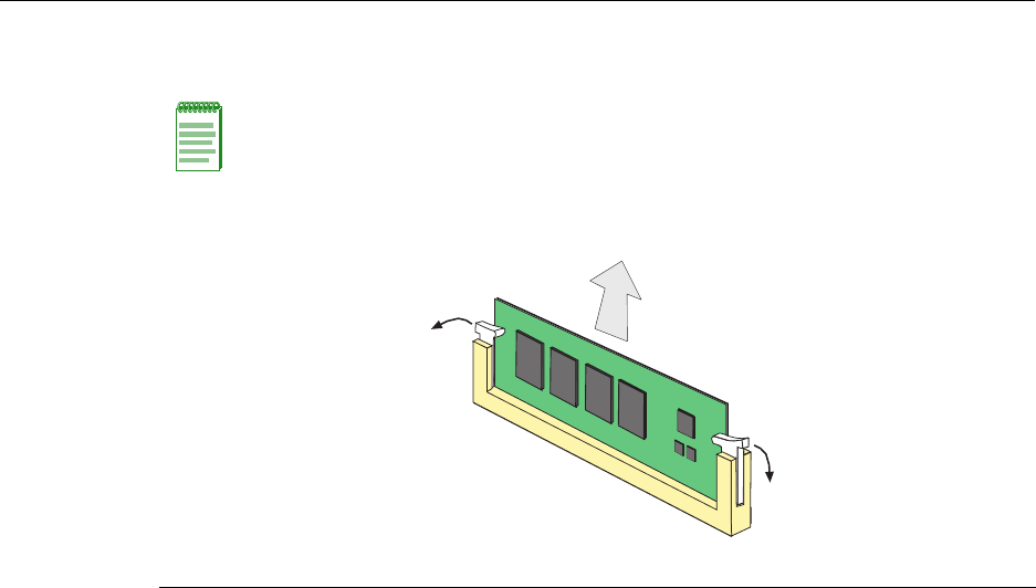
Memory Locations and Replacement Procedures
B-8 Mode Switch Bank Settings and Optional Installations
3. PushtheconnectorarmsawayfromthememorymoduletoreleasetheDRAMSIMM
fromtheconnector,asshowninFigure B‐6.
Figure B-6 DRAM SIMM Connector Location
Installing the DRAM SIMM
Toinstallthememorymodule,refertoFigure B‐7andproceedasfollows:
1. PushtheconnectorarmsawayfromtheDRAMSIMMfarenoughtoinserttheDRAM
SIMMintotheconnectorcontacts.
2. InserttheDRAMSIMMstraightdownbetweentheconnectorcontactsfarenoughfor
thetabsontheconnectorarmstoalignwiththetwoDRAMSIMMalignmentnotches.
3. PushtheDRAMSIMMdownintotheconnectorcontacts.Thenrotatethetwo
connectorarmstowardtheDRAMSIMMtolockitintoplace.
Note: The ejector arms on this connector are not spring loaded, so they will remain in the
open position until manually closed.
1Connector arms 2DRAM SIMM 3 Connector contacts
Á
Â
À
À
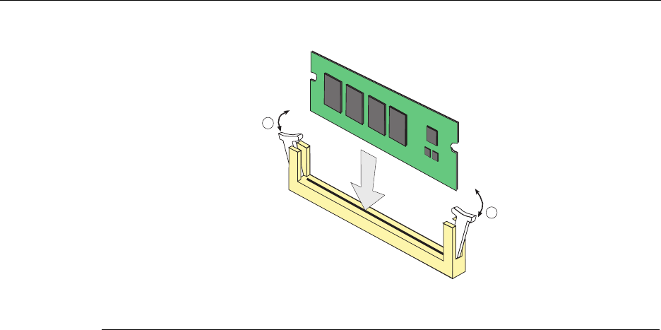
Memory Locations and Replacement Procedures
N Standalone Series Installation Guide B-9
Figure B-7 Installing the DRAM SIMM
4. Replacethechassiscoverbyre‐attachingtheprovidedscrews.
1Connector arms 3Connector contacts
2DRAM SIMM 4DRAM SIMM alignment notches (2)
Á
Â
1
1
Ã
Ã

Memory Locations and Replacement Procedures
B-10 Mode Switch Bank Settings and Optional Installations

Index-1
Index
Numerics
1000BASE-SX/LX network connections
requirements for 2-2
100BASE-TX
requirements 2-2
10BASE-T
connection 3-5
requirements 2-2
2G4072-52
introduction to 1-2
C
Cable
Fiber Budget A-2
Cable specifications
1000BASE-SX/LX network 2-2
1000BASE-T Network 2-2
100BASE-TX network 2-2
10BASE-T network 2-2
Checklist for troubleshooting 4-4
CLI command
introduction to 1-3
COM port connections
what is needed 3-13
Connecting fiber-optic cables to Mini-GBICs 3-9
Connecting power 3-4
Connecting to a modem 3-15
Connecting to the network 3-5
Connectivity
introduction to 1-2
Console port
pinout assignments A-6
Conventions
list of document xvii
D
DIMM
replacement procedures for B-4
Document conventions
list of xvii
E
Electromagnetic Compatibility (EMC)
requirements A-6
F
Fiber budget A-2
G
Getting help xviii
GROUP SELECT button
use of the 4-1
I
Installation
connecting to the Network 3-5
Rack Mounting 3-2
Installation procedures
order of 3-1
L
LANVIEW Diagnostic LEDs
use of 1-3
LANVIEW LEDs
use of 4-1
Link Aggregation 2-1
Local Management
COM port connections 3-13
introduction to 1-2
Log-in using a console port connection 3-18
M
Management
use of 1-2
Matrix N Standalone (N SA) Series
introduction to 1-2
overview of capabilities 1-1
Memory
replacement of DIMM B-5
replacement of DRAM SIMM B-7
Memory locations
DIMM and SIMM B-4
MGBIC-02
Specifications for A-5
MGBIC-08
specifications for A-5
MGBIC-LC01
Specifications for A-3
MGBIC-LC03
Specifications for A-3
MGBIC-LC09
Specifications for A-4
MGBIC-MT01
Specifications for A-3
Mini-GBIC
specifications for A-2
Index-2
Mode Switch
setting of B-2
Module features 1-2
N
Network
connecting to 3-5
Network Requirements
list of 2-1
P
Pinout assignments
console port A-6
Pinouts
crossover 3-7, 3-8
straight-through 3-7, 3-8
Power connection 3-4
R
Receive LEDs
viewing of 4-1
Regulatory Compliance A-6
Related manuals
obtaining xvi
Required Tools B-2
S
Safety requirements A-6
Shutdown
last resort 4-6
overview 4-5
Using RESET Button 4-6
SIMMs
installing DIMM B-6
Installing the DRAM SIMM B-8
location B-4
Removing the DRAM SIMM B-7
Specifications A-1
Mini-GBICs A-2
Specifications, MGBIC-08 A-5
Specifications, MGBIC-LC01
operating range A-3
optical A-3, A-5
Specifications, MGBIC-LC09
operating range A-4, A-5
optical A-4, A-5
Specifications, MGBIC-MT01
operating range A-3
optical A-3
Standards compatibility 1-3
T
Technical support
contacting Enterasys for xviii
Transmit LEDs
viewing of 4-1
Troubleshooting 4-1
checklist for 4-4
U
Unpacking the module 3-1
V
Viewing Receive and Transmit Activity
instructions for 4-1
W
WebView
introduction to 1-2
