Enterasys Networks Securestack A2 A2H124 24P Users Manual
A2H124-24P to the manual f920cf7a-a408-4f16-b7d6-14573c187c66
2015-02-04
: Enterasys-Networks Enterasys-Networks-Enterasys-Securestack-A2-A2H124-24P-Users-Manual-366829 enterasys-networks-enterasys-securestack-a2-a2h124-24p-users-manual-366829 enterasys-networks pdf
Open the PDF directly: View PDF ![]() .
.
Page Count: 82
- SecureStack A2 A2H124-24P A2H124-48P Hardware Installation Guide
- Notice
- Contents
- About This Guide
- Introduction
- Network Requirements
- Hardware Installation
- Considerations Prior to Installation
- Required Tools
- Unpacking the Switch
- Installing the Switch on a Flat Surface
- Rack Mounting the Switch
- Connecting Stacking Cables
- Configuring Switches in a Stack
- Connecting AC and PoE Power
- Connecting to Console Port for Local Management
- Connecting to the Network
- Installing Optional Mini-GBICs
- Completing the Installation
- Troubleshooting
- Specifications
- Index

7.5x9-inch cover with bleed on 4 sides
SecureStack A2
PoE Fast Ethernet Switches
Hardware Installation Guide
A2H124-24P
A2H124-48P
P/N 9034154-03

i
Notice
Enterasys Networksreservestherighttomakechangesinspecificationsandotherinformationcontainedinthis
documentanditswebsitewithoutpriornotice.ThereadershouldinallcasesconsultEnterasys Networksto
determinewhetheranysuchchangeshavebeenmade.
Thehardware,firmware,orsoftwaredescribedinthisdocumentissubjecttochangewithoutnotice.
INNOEVENTSHALLENTERASYS NETWORKSBELIABLEFORANYINCIDENTAL,INDIRECT,SPECIAL,OR
CONSEQUENTIALDAMAGESWHATSOEVER(INCLUDINGBUTNOTLIMITEDTOLOSTPROFITS)ARISING
OUTOFORRELATEDTOTHISDOCUMENT,WEBSITE,ORTHEINFORMATIONCONTAINEDINTHEM,EVEN
IFENTERASYS NETWORKSHASBEENADVISEDOF,KNEWOF,ORSHOULDHAVEKNOWNOF,THE
POSSIBILITYOFSUCHDAMAGES.
Enterasys Networks, Inc.
50MinutemanRoad
Andover,MA01810
©2007Enterasys Networks, Inc.Allrightsreserved.
PartNumber: 9034154‐03 February2007
ENTERASYS,ENTERASYS NETWORKS,ENTERASYSMATRIX,LANVIEW,NETSIGHT,WEBVIEW,andanylogos
associatedtherewith,aretrademarksorregisteredtrademarksofEnterasys Networks, Inc.,intheUnitedStatesand
othercountries.
Allotherproductnamesmentionedinthismanualmaybetrademarksorregisteredtrademarksoftheirrespective
companies.
DocumentationURL:http://www.enterasys.com/support/manuals
DocumentacionURL:http://www.enterasys.com/support/manuals
DokumentationimInternet:http://www.enterasys.com/support/manuals
Electrical Hazard: Only qualified personnel should perform installation procedures.
Riesgo Electrico: Solamente personal calificado debe realizar procedimientos de instalacion.
Elektrischer Gefahrenhinweis: Installationen sollten nur durch ausgebildetes und qualifiziertes
Personal vorgenommen werden.
ii
REGULATORY COMPLIANCE INFORMATION
FEDERAL COMMUNICATIONS COMMISSION (FCC) NOTICE
ThisdevicecomplieswithPart15oftheFCCrules.Operationissubjecttothefollowingtwoconditions:(1)thisdevice
maynotcauseharmfulinterference,and(2)thisdevicemustacceptanyinterferencereceived,includinginterference
thatmaycauseundesiredoperation.
NOTE: ThisequipmenthasbeentestedandfoundtocomplywiththelimitsforaclassAdigitaldevice,pursuantto
Part15oftheFCCrules.Theselimitsaredesignedtoprovidereasonableprotectionagainstharmfulinterferencewhen
theequipmentisoperatedinacommercialenvironment.Thisequipmentuses,generates,andcanradiateradio
frequencyenergyandifnotinstalledinaccordancewiththeoperator’smanual,maycauseharmfulinterferenceto
radiocommunications.Operationofthisequipmentinaresidentialareaislikelytocauseinterferenceinwhichcase
theuserwillberequiredtocorrecttheinterferenceathisownexpense.
WARNING: Changesormodificationsmadetothisdevicewhicharenotexpresslyapprovedbytheparty
responsibleforcompliancecouldvoidtheuser’sauthoritytooperatetheequipment.
INDUSTRY CANADA NOTICE
ThisdigitalapparatusdoesnotexceedtheclassAlimitsforradionoiseemissionsfromdigitalapparatussetoutinthe
RadioInterferenceRegulationsoftheCanadianDepartmentofCommunications.
Leprésentappareilnumériquen’émetpasdebruitsradioélectriquesdépassantleslimitesapplicablesauxappareils
numériquesdelaclassAprescritesdansleRèglementsurlebrouillageradioélectriqueédictéparleministèredes
CommunicationsduCanada.
CLASS A ITE NOTICE
WARNING: ThisisaClassAproduct.Inadomesticenvironmentthisproductmaycauseradiointerferenceinwhich
casetheusermayberequiredtotakeadequatemeasures.
CLASE A. AVISO DE ITE
ADVERTENCIA:EsteesunproductodeClaseA.Enunambientedomésticoesteproductopuedecausar
interferenciaderadioencuyocasopuedeserrequeridotomarmedidasadecuadas.
KLASSE A ITE ANMERKUNG
WARNHINWEIS:DiesesProduktzähltzurKlasseA(Industriebereich).InWohnbereichenkanneshierdurchzu
Funkstörungenkommen,dahersolltenangemesseneVorkehrungenzumSchutzgetroffenwerden.
PRODUCT SAFETY
Thisproductcomplieswiththefollowing:UL60950,CSAC22.2No.60950,73/23/EEC,EN60950,IEC60950,EN 60825,
21 CFR1040.10.
SEGURIDAD DEL PRODUCTO
ElproductodeEnterasyscumpleconlosiguiente:UL60950,CSAC22.2No.60950,73/23/EEC,EN 60950,IEC 60950,
EN 60825,21 CFR1040.10.
PRODUKTSICHERHEIT
DiesesProduktentsprichtdenfolgendenRichtlinien:UL60950,CSAC22.2No.60950,73/23/EEC,EN60950,
IEC 60950,EN60825,21CFR1040.10.
iii
ELECTROMAGNETIC COMPATIBILITY (EMC)
Thisproductcomplieswiththefollowing:47CFRParts2and15,CSAC108.8,89/336/EEC,EN55022,EN61000‐3‐2,
EN 61000‐3‐3,EN55024,AS/NZSCISPR22,VCCIV‐3.
COMPATIBILIDAD ELECTROMÁGNETICA (EMC)
EsteproductodeEnterasyscumpleconlosiguiente:47CFRPartes2y15,CSAC108.8,89/336/EEC,EN55022,
EN 55024,EN61000‐3‐2,EN61000‐3‐3,AS/NZSCISPR22,VCCIV‐3.
ELEKTRO- MAGNETISCHE KOMPATIBILITÄT ( EMC )
DiesesProduktentsprichtdenfolgendenRichtlinien:47CFRParts2and15,CSAC108.8,89/336/EEC,EN55022,
EN 61000‐3‐2,EN61000‐3‐3,EN55024,AS/NZSCISPR22,VCCIV‐3.
HAZARDOUS SUBSTANCES
ThisproductcomplieswiththerequirementsofEuropeanDirective,2002/95/EC,RestrictionofHazardousSubstances
(RoHS)inElectricalandElectronicEquipment.
EUROPEAN WASTE ELECTRICAL AND ELECTRONIC EQUIPMENT (WEEE) NOTICE
InaccordancewithDirective2002/96/ECoftheEuropeanParliamentonwasteelectricalandelectronicequipment
(WEEE):
1. Thesymbolaboveindicatesthatseparatecollectionofelectricalandelectronicequipmentisrequiredandthatthis
productwasplacedontheEuropeanmarketafterAugust13,2005,thedateofenforcementforDirective
2002/96/EC.
2. Whenthisproducthasreachedtheendofitsserviceablelife,itcannotbedisposedofasunsortedmunicipalwaste.
Itmustbecollectedandtreatedseparately.
3. IthasbeendeterminedbytheEuropeanParliamentthattherearepotentialnegativeeffectsontheenvironment
andhumanhealthasaresultofthepresenceofhazardoussubstancesinelectricalandelectronicequipment.
4. Itistheusers’responsibilitytoutilizetheavailablecollectionsystemtoensureWEEEisproperlytreated.
Forinformationabouttheavailablecollectionsystem,pleasegotohttp://www.enterasys.com/services/support/or
contactEnterasysCustomerSupportat35361705586(Ireland).

iv

v
VCCI NOTICE
ThisisaclassAproductbasedonthestandardoftheVoluntaryControlCouncilforInterferencebyInformation
TechnologyEquipment(VCCI).Ifthisequipmentisusedinadomesticenvironment,radiodisturbancemayarise.
Whensuchtroubleoccurs,theusermayberequiredtotakecorrectiveactions.
BSMI EMC STATEMENT — TAIWAN
ThisisaclassAproduct.Inadomesticenvironmentthisproductmaycauseradiointerferenceinwhichcasetheuser
mayberequiredtotakeadequatemeasures.
SAFETY INFORMATION
CLASS 1 LASER TRANSCEIVERS
SINGLE MODE NETWORK EXPANSION MODULES USE CLASS 1 LASER TRANSCEIVERS.
READ THE FOLLOWING SAFETY INFORMATION
BEFORE INSTALLING OR OPERATING THESE MODULES.
TheClass1lasertransceiversuseanopticalfeedbacklooptomaintainClass1operationlimits.Thiscontrolloop
eliminatestheneedformaintenancechecksoradjustments.Theoutputisfactoryset,anddoesnotallowanyuser
adjustment.Class1Lasertransceiverscomplywiththefollowingsafetystandards:
•21CFR1040.10and1040.11U.S.DepartmentofHealthandHumanServices(FDA).
•IECPublication825(InternationalElectrotechnicalCommission).
• CENELECEN60825(EuropeanCommitteeforElectrotechnicalStandardization).
Whenoperatingwithintheirperformancelimitations,lasertransceiveroutputmeetstheClass1accessibleemission
limitofallthreestandards.Class1levelsoflaserradiationarenotconsideredhazardous.
Whentheconnectorisinplace,alllaserradiationremainswithinthefiber.Themaximumamountofradiantpower
exitingthefiber(undernormalconditions)is‐12.6dBmor55x10‐6watts.
Removingtheopticalconnectorfromthetransceiverallowslaserradiationtoemitdirectlyfromtheopticalport.The
maximumradiancefromtheopticalport(underworstcaseconditions)is0.8Wcm‐2or8x103Wm2sr‐1.
Donotuseopticalinstrumentstoviewthelaseroutput.Theuseofopticalinstrumentstoviewlaseroutputincreases
eyehazard.Whenviewingtheoutputopticalport,powermustberemovedfromthenetworkadapter.
vi
DECLARATION OF CONFORMITY
ApplicationofCouncilDirective(s): 89/336/EEC
73/23/EEC
Manufacturer’sName: Enterasys Networks, Inc.
Manufacturer’sAddress: 50MinutemanRoad
Andover,MA01810
USA
EuropeanRepresentativeAddress: Enterasys Networks,Ltd.
NexusHouse,NewburyBusinessPark
LondonRoad,Newbury
BerkshireRG142PZ,England
Conformance to Directive(s)/Product Standards: ECDirective89/336/EEC
EN55022
EN61000‐3‐2
EN61000‐3‐3
EN55024
ECDirective73/23/EEC
EN60950
EN60825
EquipmentType/Environment: NetworkingEquipment,foruseinaCommercial
orLightIndustrialEnvironment.
Enterasys Networks, Inc.declaresthattheequipmentpackagedwiththisnoticeconformstotheabovedirectives.
vii
ENTERASYS NETWORKS, INC.
FIRMWARE LICENSE AGREEMENT
BEFOREOPENINGORUTILIZINGTHEENCLOSEDPRODUCT,
CAREFULLYREADTHISLICENSEAGREEMENT.
Thisdocumentisanagreement(“Agreement”)betweentheenduser(“You”)andEnterasys Networks, Inc.onbehalf
ofitselfanditsAffiliates(ashereinafterdefined)(“Enterasys”)thatsetsforthYourrightsandobligationswithrespect
totheEnterasyssoftwareprogram/firmwareinstalledontheEnterasysproduct(includinganyaccompanying
documentation,hardwareormedia)(“Program”)inthepackageandprevailsoveranyadditional,conflictingor
inconsistenttermsandconditionsappearingonanypurchaseorderorotherdocumentsubmittedbyYou.“Affiliate”
meansanyperson,partnership,corporation,limitedliabilitycompany,orotherformofenterprisethatdirectlyor
indirectlythroughoneormoreintermediaries,controls,oriscontrolledby,orisundercommoncontrolwiththeparty
specified.ThisAgreementconstitutestheentireunderstandingbetweentheparties,andsupersedesallprior
discussions,representations,understandingsoragreements,whetheroralorinwriting,betweenthepartieswith
respecttothesubjectmatterofthisAgreement.TheProgrammaybecontainedinfirmware,chipsorothermedia.
BYINSTALLINGOROTHERWISEUSINGTHEPROGRAM,YOUREPRESENTTHATYOUAREAUTHORIZEDTO
ACCEPTTHESETERMSONBEHALFOFTHEENDUSER(IFTHEENDUSERISANENTITYONWHOSEBEHALF
YOUAREAUTHORIZEDTOACT,“YOU”AND“YOUR”SHALLBEDEEMEDTOREFERTOSUCHENTITY)AND
THATYOUAGREETHATYOUAREBOUNDBYTHETERMSOFTHISAGREEMENT,WHICHINCLUDES,
AMONGOTHERPROVISIONS,THELICENSE,THEDISCLAIMEROFWARRANTYANDTHELIMITATIONOF
LIABILITY.IFYOUDONOTAGREETOTHETERMSOFTHISAGREEMENTORARENOTAUTHORIZEDTO
ENTERINTOTHISAGREEMENT,ENTERASYSISUNWILLINGTOLICENSETHEPROGRAMTOYOUANDYOU
AGREETORETURNTHEUNOPENEDPRODUCTTOENTERASYSORYOURDEALER,IFANY,WITHINTEN
(10)DAYSFOLLOWINGTHEDATEOFRECEIPTFORAFULLREFUND.
IFYOUHAVEANYQUESTIONSABOUTTHISAGREEMENT,CONTACTENTERASYS NETWORKS,LEGAL
DEPARTMENTAT(978)684‐1000.
YouandEnterasysagreeasfollows:
1. LICENSE. Youhavethenon‐exclusiveandnon‐transferablerighttouseonlytheone(1)copyoftheProgram
providedinthispackagesubjecttothetermsandconditionsofthisAgreement.
2. RESTRICTIONS. ExceptasotherwiseauthorizedinwritingbyEnterasys,Youmaynot,normayYoupermitany
thirdpartyto:
(i) Reverseengineer,decompile,disassembleormodifytheProgram,inwholeorinpart,includingforreasons
oferrorcorrectionorinteroperability,excepttotheextentexpresslypermittedbyapplicablelawandtothe
extentthepartiesshallnotbepermittedbythatapplicablelaw,suchrightsareexpresslyexcluded.
InformationnecessarytoachieveinteroperabilityorcorrecterrorsisavailablefromEnterasysuponrequest
anduponpaymentofEnterasys’applicablefee.
(ii) IncorporatetheProgram,inwholeorinpart,inanyotherproductorcreatederivativeworksbasedonthe
Program,inwholeorinpart.
(iii) Publish,disclose,copy,reproduceortransmittheProgram,inwholeorinpart.
(iv) Assign,sell,license,sublicense,rent,lease,encumberbywayofsecurityinterest,pledgeorotherwisetransfer
theProgram,inwholeorinpart.
(v) Removeanycopyright,trademark,proprietaryrights,disclaimerorwarningnoticeincludedonorembedded
inanypartoftheProgram.
viii
3. APPLICABLELAW. ThisAgreementshallbeinterpretedandgovernedunderthelawsandinthestateand
federalcourtsoftheCommonwealthofMassachusettswithoutregardtoitsconflictsoflawsprovisions.Youacceptthe
personaljurisdictionandvenueoftheCommonwealthofMassachusettscourts.Noneofthe1980UnitedNations
ConventiononContractsfortheInternationalSaleofGoods,theUnitedNationsConventionontheLimitationPeriod
intheInternationalSaleofGoods,andtheUniformComputerInformationTransactionsActshallapplytothis
Agreement.
4. EXPORTRESTRICTIONS. YouunderstandthatEnterasysanditsAffiliatesaresubjecttoregulationbyagencies
oftheU.S.Government,includingtheU.S.DepartmentofCommerce,whichprohibitexportordiversionofcertain
technicalproductstocertaincountries,unlessalicensetoexporttheProgramisobtainedfromtheU.S.Governmentor
anexceptionfromobtainingsuchlicensemayberelieduponbytheexportingparty.
IftheProgramisexportedfromtheUnitedStatespursuanttotheLicenseExceptionCIVundertheU.S.Export
AdministrationRegulations,YouagreethatYouareacivilenduseroftheProgramandagreethatYouwillusethe
Programforcivilendusesonlyandnotformilitarypurposes.
IftheProgramisexportedfromtheUnitedStatespursuanttotheLicenseExceptionTSRundertheU.S.Export
AdministrationRegulations,inadditiontotherestrictionontransfersetforthinSections1or2ofthisAgreement,You
agreenotto(i)reexportorreleasetheProgram,thesourcecodefortheProgramortechnologytoanationalofa
countryinCountryGroupsD:1orE:2(Albania,Armenia,Azerbaijan,Belarus,Bulgaria,Cambodia,Cuba,Estonia,
Georgia,Iraq,Kazakhstan,Kyrgyzstan,Laos,Latvia,Libya,Lithuania,Moldova,NorthKorea,thePeople’sRepublic
ofChina,Romania,Russia,Rwanda,Tajikistan,Turkmenistan,Ukraine,Uzbekistan,Vietnam,orsuchothercountries
asmaybedesignatedbytheUnitedStatesGovernment),(ii)exporttoCountryGroupsD:1orE:2(asdefinedherein)
thedirectproductoftheProgramorthetechnology,ifsuchforeignproduceddirectproductissubjecttonational
securitycontrolsasidentifiedontheU.S.CommerceControlList,or(iii)ifthedirectproductofthetechnologyisa
completeplantoranymajorcomponentofaplant,exporttoCountryGroupsD:1orE:2thedirectproductoftheplant
oramajorcomponentthereof,ifsuchforeignproduceddirectproductissubjecttonationalsecuritycontrolsas
identifiedontheU.S.CommerceControlListorissubjecttoStateDepartmentcontrolsundertheU.S.MunitionsList.
5. UNITEDSTATESGOVERNMENTRESTRICTEDRIGHTS. TheenclosedProgram(i)wasdevelopedsolelyat
privateexpense;(ii)contains“restrictedcomputersoftware”submittedwithrestrictedrightsinaccordancewithsection
52.227‐19(a)through(d)oftheCommercialComputerSoftware‐RestrictedRightsClauseanditssuccessors,and(iii)in
allrespectsisproprietarydatabelongingtoEnterasysand/oritssuppliers.ForDepartmentofDefenseunits,the
ProgramisconsideredcommercialcomputersoftwareinaccordancewithDFARSsection227.7202‐3anditssuccessors,
anduse,duplication,ordisclosurebytheGovernmentissubjecttorestrictionssetforthherein.
6. DISCLAIMEROFWARRANTY. EXCEPTFORTHOSEWARRANTIESEXPRESSLYPROVIDEDTOYOUIN
WRITINGBYENTERASYS,ENTERASYSDISCLAIMSALLWARRANTIES,EITHEREXPRESSORIMPLIED,
INCLUDINGBUTNOTLIMITEDTOIMPLIEDWARRANTIESOFMERCHANTABILITY,SATISFACTORY
QUALITY,FITNESSFORAPARTICULARPURPOSE,TITLEANDNON‐INFRINGEMENTWITHRESPECTTOTHE
PROGRAM.IFIMPLIEDWARRANTIESMAYNOTBEDISCLAIMEDBYAPPLICABLELAW,THENANYIMPLIED
WARRANTIESARELIMITEDINDURATIONTOTHIRTY(30)DAYSAFTERDELIVERYOFTHEPROGRAMTO
YOU.
7. LIMITATIONOFLIABILITY. INNOEVENTSHALLENTERASYSORITSSUPPLIERSBELIABLEFORANY
DAMAGESWHATSOEVER(INCLUDING,WITHOUTLIMITATION,DAMAGESFORLOSSOFBUSINESS,
PROFITS,BUSINESSINTERRUPTION,LOSSOFBUSINESSINFORMATION,SPECIAL,INCIDENTAL,
CONSEQUENTIAL,ORRELIANCEDAMAGES,OROTHERLOSS)ARISINGOUTOFTHEUSEORINABILITYTO
USETHEPROGRAM,EVENIFENTERASYSHASBEENADVISEDOFTHEPOSSIBILITYOFSUCHDAMAGES.
THISFOREGOINGLIMITATIONSHALLAPPLYREGARDLESSOFTHECAUSEOFACTIONUNDERWHICH
DAMAGESARESOUGHT.
ix
THECUMULATIVELIABILITYOFENTERASYSTOYOUFORALLCLAIMSRELATINGTOTHEPROGRAM,
INCONTRACT,TORTOROTHERWISE,SHALLNOTEXCEEDTHETOTALAMOUNTOFFEESPAIDTO
ENTERASYSBYYOUFORTHERIGHTSGRANTEDHEREIN.
8. AUDITRIGHTS. YouherebyacknowledgethattheintellectualpropertyrightsassociatedwiththeProgramare
ofcriticalvaluetoEnterasysand,accordingly,Youherebyagreeto maintaincompletebooks,recordsandaccounts
showing(i)licensefeesdueandpaid,and(ii)theuse,copyinganddeploymentoftheProgram.Youalsograntto
Enterasysanditsauthorizedrepresentatives,uponreasonablenotice,therightto auditandexamineduringYour
normalbusinesshours,Yourbooks,records,accountsandhardwaredevicesuponwhichtheProgrammaybedeployed
toverifycompliancewiththisAgreement,includingtheverificationofthelicensefeesdueandpaidEnterasysandthe
use,copyinganddeploymentoftheProgram.Enterasys’rightofexamination shallbeexercisedreasonably,ingood
faithandinamannercalculatedtonotunreasonablyinterferewithYourbusiness.Intheeventsuchauditdiscovers
non‐compliancewiththisAgreement,includingcopiesoftheProgrammade,usedordeployedinbreachofthis
Agreement,YoushallpromptlypaytoEnterasystheappropriatelicensefees.Enterasys reservestheright,tobe
exercisedinitssolediscretionandwithoutpriornotice,toterminatethislicense,effectiveimmediately,forfailureto
complywiththisAgreement.Uponanysuchtermination,YoushallimmediatelyceasealluseoftheProgramandshall
returntoEnterasystheProgramandallcopiesoftheProgram.
9. OWNERSHIP. Thisisalicenseagreementandnotanagreementforsale.Youacknowledgeandagreethatthe
Programconstitutestradesecretsand/orcopyrightedmaterialofEnterasysand/oritssuppliers.Youagreeto
implementreasonablesecuritymeasurestoprotectsuchtradesecretsandcopyrightedmaterial.Allright,titleand
interestinandtotheProgramshallremainwithEnterasysand/oritssuppliers.Allrightsnotspecificallygrantedto
YoushallbereservedtoEnterasys.
10. ENFORCEMENT. YouacknowledgeandagreethatanybreachofSections2,4,or9ofthisAgreementbyYoumay
causeEnterasysirreparabledamageforwhichrecoveryofmoneydamageswouldbeinadequate,andthatEnterasys
maybeentitledtoseektimelyinjunctiverelieftoprotectEnterasys’rightsunderthisAgreementinadditiontoanyand
allremediesavailableatlaw.
11. ASSIGNMENT. Youmaynotassign,transferorsublicensethisAgreementoranyofYourrightsorobligations
underthisAgreement,exceptthatYoumayassignthisAgreementtoanypersonorentitywhichacquiressubstantially
allofYourstockorassets.EnterasysmayassignthisAgreementinitssolediscretion.ThisAgreementshallbebinding
uponandinuretothebenefitoftheparties,theirlegalrepresentatives,permittedtransferees,successorsandassignsas
permittedbythisAgreement.Anyattemptedassignment,transferorsublicenseinviolationofthetermsofthis
AgreementshallbevoidandabreachofthisAgreement.
12. WAIVER. AwaiverbyEnterasysofabreachofanyofthetermsandconditionsofthisAgreementmustbein
writingandwillnotbeconstruedasawaiverofanysubsequentbreachofsuchtermorcondition.Enterasys’failureto
enforceatermuponYourbreachofsuchtermshallnotbeconstruedasawaiverofYourbreachorpreventenforcement
onanyotheroccasion.
13. SEVERABILITY. IntheeventanyprovisionofthisAgreementisfoundtobeinvalid,illegalorunenforceable,the
validity,legalityandenforceabilityofanyoftheremainingprovisionsshallnotinanywaybeaffectedorimpaired
thereby,andthatprovisionshallbereformed,construedandenforcedtothemaximumextentpermissible.Anysuch
invalidity,illegalityorunenforceabilityinanyjurisdictionshallnotinvalidateorrenderillegalorunenforceablesuch
provisioninanyotherjurisdiction.
14. TERMINATION. EnterasysmayterminatethisAgreementimmediatelyuponYourbreachofanyoftheterms
andconditionsofthisAgreement.Uponanysuchtermination,YoushallimmediatelyceasealluseoftheProgramand
shallreturntoEnterasystheProgramandallcopiesoftheProgram.
x

xi
Contents
About This Guide
Who Should Use This Guide ............................................................................................................... xv
How to Use This Guide ...................................................................................................................... xvi
Related Documents ........................................................................................................................... xvi
Conventions Used in This Guide .......................................................................................................xvii
Chapter 1: Introduction
Overview ............................................................................................................................................1-2
A2H124-24P and A2H124-48P ...................................................................................................1-2
Stack Connections .......................................................................................................................1-4
Redundant Power Supply Capability ...........................................................................................1-4
PoE (Power over Ethernet) Support ..................................................................................................1-4
Connectivity .......................................................................................................................................1-5
Management ......................................................................................................................................1-6
Switch Configuration Using WebView .........................................................................................1-6
Switch Configuration Using CLI Commands ...............................................................................1-6
Standards Compatibility .....................................................................................................................1-6
LANVIEW Diagnostic LEDs ...............................................................................................................1-7
Getting Help .......................................................................................................................................1-7
Chapter 2: Network Requirements
10BASE-T Network ............................................................................................................................2-1
100BASE-TX Network .......................................................................................................................2-2
1000BASE-FX Network .....................................................................................................................2-2
1000BASE-T Network ........................................................................................................................2-2
Chapter 3: Hardware Installation
Considerations Prior to Installation ....................................................................................................3-2
Required Tools ...................................................................................................................................3-2
Unpacking the Switch ........................................................................................................................3-2
Installing the Switch on a Flat Surface ...............................................................................................3-3
Installing the Rubber Feet ...........................................................................................................3-3
Guidelines for Flat Surface Installation ........................................................................................3-5
Rack Mounting the Switch ................................................................................................................3-6
Guidelines for Rackmount Installation .........................................................................................3-6
Attaching Brackets and Installing in Rack ...................................................................................3-6
Connecting Stacking Cables ..............................................................................................................3-7
Configuring Switches in a Stack ........................................................................................................3-9
About SecureStack A2 Switch Operation in a Stack ...................................................................3-9
Recommended Procedures for New and Existing Stacks .........................................................3-10
xii
Connecting AC and PoE Power .......................................................................................................3-12
AC Power ..................................................................................................................................3-12
C2RPS-PoE Redundant Power System ....................................................................................3-13
Stack Initialization Overview ......................................................................................................3-14
Connecting to Console Port for Local Management ........................................................................3-14
What Is Needed .........................................................................................................................3-15
Connecting to an IBM or Compatible Device .............................................................................3-16
Connecting to a VT Series Terminal ..........................................................................................3-17
Connecting to a Modem ............................................................................................................3-18
Connecting to the Network ...............................................................................................................3-19
Connecting UTP Cables ............................................................................................................3-19
Installing Optional Mini-GBICs .........................................................................................................3-22
Removing the Mini-GBIC ...........................................................................................................3-26
Connecting Fiber-Optic Cables to MT-RJ Ports ........................................................................3-27
Connecting Fiber-Optic Cables to LC Ports ..............................................................................3-30
Completing the Installation ...............................................................................................................3-32
Initial Logon to Switch Management ..........................................................................................3-32
Chapter 4: Troubleshooting
Using LANVIEW .................................................................................................................................4-2
Troubleshooting Checklist ..................................................................................................................4-7
Using the Reset Password Switch .....................................................................................................4-9
Appendix A: Specifications
Switch Specifications ........................................................................................................................ A-1
Mini-GBIC Input/Output Specifications ............................................................................................. A-4
Gigabit Ethernet Specifications ......................................................................................................... A-4
MGBIC-LC01/MGBIC-MT01 Specifications (1000BASE-SX) ..................................................... A-4
MGBIC-LC03 Specifications (1000BASE-SX) ............................................................................ A-5
MGBIC-LC09 Specifications (1000BASE-LX) ............................................................................ A-6
MGBIC-08 Specifications (1000BASE-ELX) .............................................................................. A-6
MGBIC-02 Specifications (1000BASE-T) ................................................................................... A-7
Console Port Pinout Assignments .................................................................................................... A-7
Regulatory Compliance ..................................................................................................................... A-8
Index
xiii
Figures
1-1 A2H124-24P Stackable Switch ..............................................................................................1-3
1-2 A2H124-48P Stackable Switch ..............................................................................................1-3
3-1 Chassis Bottom, Rubber Feet Placement..............................................................................3-4
3-2 Area Guidelines for Switch Installation on Flat Surface .........................................................3-5
3-3 Attaching the Rackmount Brackets........................................................................................3-6
3-4 Fastening the Switch to the Rack...........................................................................................3-7
3-5 Stacking Cable Connections..................................................................................................3-8
3-6 Switch Rear View (A2H124-48P shown) .............................................................................3-12
3-7 Accessing the RPS connector..............................................................................................3-13
3-8 DB9 Male Console Port Pinout Assignments.......................................................................3-15
3-9 Connecting an IBM PC or Compatible .................................................................................3-16
3-10 Connecting a VT Series Terminal ........................................................................................3-17
3-11 Connecting to a Modem.......................................................................................................3-18
3-12 Connecting a UTP Cable Segment to RJ45 Port.................................................................3-20
3-13 Four-Wire Crossover Cable RJ45 Pinouts for 10/100BASE-TX ..........................................3-21
3-14 Four-Wire Straight-Through Cable RJ45 Pinouts for 10/100BASE-TX................................3-21
3-15 Eight-Wire Crossover Cable RJ45 Pinouts for 1000BASE-TX.............................................3-21
3-16 Eight-Wire Straight-Through Cable RJ45 Pinouts for 1000BASE-TX..................................3-22
3-17 Mini-GBIC with RJ45 Connector ..........................................................................................3-24
3-18 Mini-GBIC with MT-RJ Connector........................................................................................3-25
3-19 Mini-GBIC with LC Connector..............................................................................................3-26
3-20 Cable Connection to MT-RJ Multimode Fiber-Optic Connectors .........................................3-29
3-21 Cable Connection to LC Fiber-Optic Connectors.................................................................3-31
4-1 LANVIEW LEDs of A2H124-24P............................................................................................4-2
4-2 LANVIEW LEDs of A2H124-48P............................................................................................4-2
4-3 Reset Password Switch .........................................................................................................4-9
A-1 Console Port Pinout Assignments......................................................................................... A-7
Tables
1-1 Power Device Classifications.................................................................................................1-5
1-2 Description of Mini-GBICs......................................................................................................1-5
3-1 Contents of Switch Carton .....................................................................................................3-2
4-1 LANVIEW LEDs .....................................................................................................................4-3
4-2 Troubleshooting Checklist......................................................................................................4-7
A-1 A2H124-24P Switch Specifications....................................................................................... A-1
A-2 A2H124-48P Switch Specifications....................................................................................... A-3
A-3 Mini-GBIC Input/Output Port Specifications.......................................................................... A-4
A-4 MGBIC-LC01/MGBIC-MT01 Optical Specifications.............................................................. A-4
A-5 MGBIC-LC01/MGBIC-MT01 Operating Range ..................................................................... A-5
A-6 MGBIC-LC03 Optical Specifications ..................................................................................... A-5
A-7 MGBIC-LC03 Operating Range ............................................................................................ A-5
A-8 MGBIC-LC09 Optical Specifications ..................................................................................... A-6
A-9 MGBIC-LC09 Operating Range ............................................................................................ A-6
A-10 MGBIC-08 Optical Specifications.......................................................................................... A-6
xiv
A-11 MGBIC-08 Operating Range................................................................................................. A-6
A-12 MGBIC-02 Specifications...................................................................................................... A-7
A-13 Compliance Standards.......................................................................................................... A-8

SecureStack A2 PoE Installation Guide xv
About This Guide
Thisguideprovidesanoverview,installationandtroubleshootinginstructions,and
specificationsfortheEnterasys®SecureStackA2H124‐24PandA2H124‐48Pstackable
Ethernetswitches.
ForinformationabouttheCommandLineInterface(CLI)setofcommandsusedto
configureandmanagetheswitches,refertotheEnterasys Networks®SecureStackA2
ConfigurationGuide.
Who Should Use This Guide
Thisguideisintendedforanetworkadministratorresponsibleforinstallingandsetting
upthestackableswitches.
Note: In this guide, the following terms are used:
•Switch refers to all switches (A2H124-24P and A2H124-48P)unless otherwise noted.
•MGBIC (Mini-Gigabit Interface Card) refers to optional small form pluggable (SFP)
interface modules that plug into the fixed front panel MGBIC slots.
•PoE refers to Power over Ethernet (IEEE 802.3af).
•PD (Powered Device) Device that receives power from the transmission line.
Important Notice
Depending on the firmware version used in the A2H124-24P and A2H124-48P switches, some
features described in this document may not be supported. Refer to the Release Notes shipped with
the SecureStack A2 to determine which features are supported.
Electrical Hazard: Only qualified personnel should perform installation procedures.
Riesgo Electrico: Solamente personal calificado debe realizar procedimientos de
instalacion.
Elektrischer Gefahrenhinweis: Installationen sollten nur durch ausgebildetes und
qualifiziertes Personal vorgenommen werden.

How to Use This Guide
xvi About This Guide
How to Use This Guide
Readthroughthisguidecompletelytofamiliarizeyourselfwithitscontentsandgainan
understandingofthefeaturesandcapabilitiesofthestackableEthernetswitches.A
generalknowledgeofdatacommunicationsnetworksishelpfulwhensettingupthe
switches.
ThisprefaceprovidesanoverviewofthisguideandtheSecureStackA2manualset,a
briefsummaryofeachchapteranddefinestheconventionsusedthroughoutthisguide.
Tolocateinformationconcerningvarioussubjectsinthisguide,refertothefollowing
table:
Related Documents
Thefollowingdocumentscanhelpyoutosetupandmanagetheswitch:
•SecureStackA2ConfigurationGuidedescribeshowtousetheCommandLineInterface
(CLI)tosetupandmanagetheA2switches.
•CablingGuideprovidesinformationconcerningnetworkcabling,dBloss,andother
cablingspecificationsandusage.
ThemanualslistedabovecanbeobtainedfromtheWorldWideWebinAdobeAcrobat
PortableDocumentFormat(PDF)atthefollowingsite:
http://www.enterasys.com/support/manuals
UnliketheSecureStackA2ConfigurationGuide,theCablingGuideisnotlisted
alphabeticallyonthewebsite.Instead,itisundertheOverviewGuideslink.
For... Refer to...
An overview of the SecureStack A2 features and
how to obtain technical support
Chapter 1, Introduction
Network requirements that must be met before
installing the SecureStack A2
Chapter 2, Network Requirements
Instructions to install the SecureStack A2 on a flat
surface or in a standard 19-inch rack and
configure the SecureStack A2 in a stacked
configuration
Chapter 3, Hardware Installation
Troubleshooting installation problems and
diagnosing network/operational problems using
the LANVIEW LEDs
Chapter 4, Troubleshooting
Specifications, environmental requirements, and
physical properties of the SecureStack A2 and
optional Mini-GBICs
Appendix A, Specifications

Conventions Used in This Guide
SecureStack A2 PoE Installation Guide xvii
Conventions Used in This Guide
Thefollowingconventionsareusedinthisguide:
Note: Calls the reader’s attention to any item of information that may be of special
importance.
Caution: Contains information essential to avoid damage to the equipment.
Precaución: Contiene información esencial para prevenir dañar el equipo.
Achtung: Verweißt auf wichtige Informationen zum Schutz gegen Beschädigungen.
Electrical Hazard: Warns against an action that could result in personal injury or death
due to an electrical hazard.
Riesgo Electrico: Advierte contra una acción que pudiera resultar en lesión corporal o la
muerte debido a un riesgo eléctrico.
Elektrischer Gefahrenhinweis: Warnung vor sämtlichen Handlungen, die zu Verletzung
von Personen oder Todesfällen – hervorgerufen durch elektrische Spannung – führen
können!
Warning: Warns against an action that could result in personal injury or death.
Advertencia: Advierte contra una acción que pudiera resultar en lesión corporal o la
muerte.
Warhinweis: Warnung vor Handlungen, die zu Verletzung von Personen oder gar
Todesfällen führen können!

Conventions Used in This Guide
xviii About This Guide

SecureStack A2 PoE Installation Guide 1-1
1
Introduction
ThischapterintroducestheA2H124‐24Pand A2H124‐48Pstackableswitches.
Important Notice
Depending on the firmware version used in the SecureStack A2, some features described in this
document may not be supported. Refer to the Release Notes shipped with the switch to determine
which features are supported.
For information about... Refer to page...
Overview 1-2
Connectivity 1-5
Management 1-6
Standards Compatibility 1-6
LANVIEW Diagnostic LEDs 1-7
Getting Help 1-7

Overview
1-2 Introduction
Overview
TheA2H124‐24PandA2H124‐48ParestackableFastEthernetswitches,whichcanbe
adaptedandscaledtohelpmeetyournetworkneeds.Theseswitchesprovidea
managementplatformanduplinktoanetworkbackboneforastackedgroupofupto
eightA2switches.Thetwobuilt‐inSmallFormPluggable(SFP)interfaceslotsprovide
youwiththeoptionofinstallingMini‐GBICsfor1000BASE‐SX/LX/ELXfiber‐optic
connectionsand1000BASE‐Tcopperconnections.
TheswitchesalsosupporttheuseofaredundantDCpowersupplytohelpprevent
downtimeduetoaninternalpowersupplyfailureintheswitchorACpowersource.
YoucaninstalltheSecureStackA2 onaflatsurfaceorintoastandard19‐inchrackwith
user‐suppliedmountinghardware,andconfiguretheSecureStackA2functionsusingthe
WebView™application,CLIswitchingcommands,and/orSNMP.
A2H124-24P and A2H124-48P
TheA2H124‐24P(Figure 1‐1)andA2H124‐48P(Figure 1‐2)haveseveraltypesoffront
panelportconnections,whichinclude:
•RJ45ports(10/100Mbps,100BASE‐Tcopperports),24ontheA2H124‐24Pand48on
theA2H124‐48P.
•SFPslotslabeledport27and28ontheA2H124‐24Pand51and52ontheA2H124‐48P
thatprovideyouwiththeoptionofinstallingSmallFormPluggable(SFP)
Mini‐GBICsfor1000BASE‐SX/LX/ELXfiber‐opticconnectionsand1000BASE‐T
copperconnections.
• 1000BASE‐TRJ45stackconnectorswhichcanbeusedinastackconfigurationaswell
asstandardswitchportswhenconfiguredasastandaloneswitch.
•RearpanelRedundantPowerSupplyconnectorusedtoconnecttoaSecureStack
C2RPS‐POEpowersupplysystemusingtheappropriatecable(C2RPS‐POEcable).
The10/100 Mbpsfixedfrontpanelportscanoperateineitherhalf‐duplexorfull‐duplex
mode,asdeterminedbyAuto‐Negotiation.
Caution: The A2H124-24P and A2H124-48P are PoE-compliant devices. Do not connect
a SecureStack C2 Redundant Power System (C2RPS-SYS) to the power connector.
Otherwise, damage to the device may result.
Precaución: Los dispositivos A2H124-24P y A2H124-48P cumplen con el estándar PoE
(power over ethernet). No conecte una fuente de poder redundante (RPS) SecureStack
C2 (C2RPS-SYS) al cable de corriente. De lo contrario, el dispositivo puede dañarse.
Overview
SecureStack A2 PoE Installation Guide 1-3
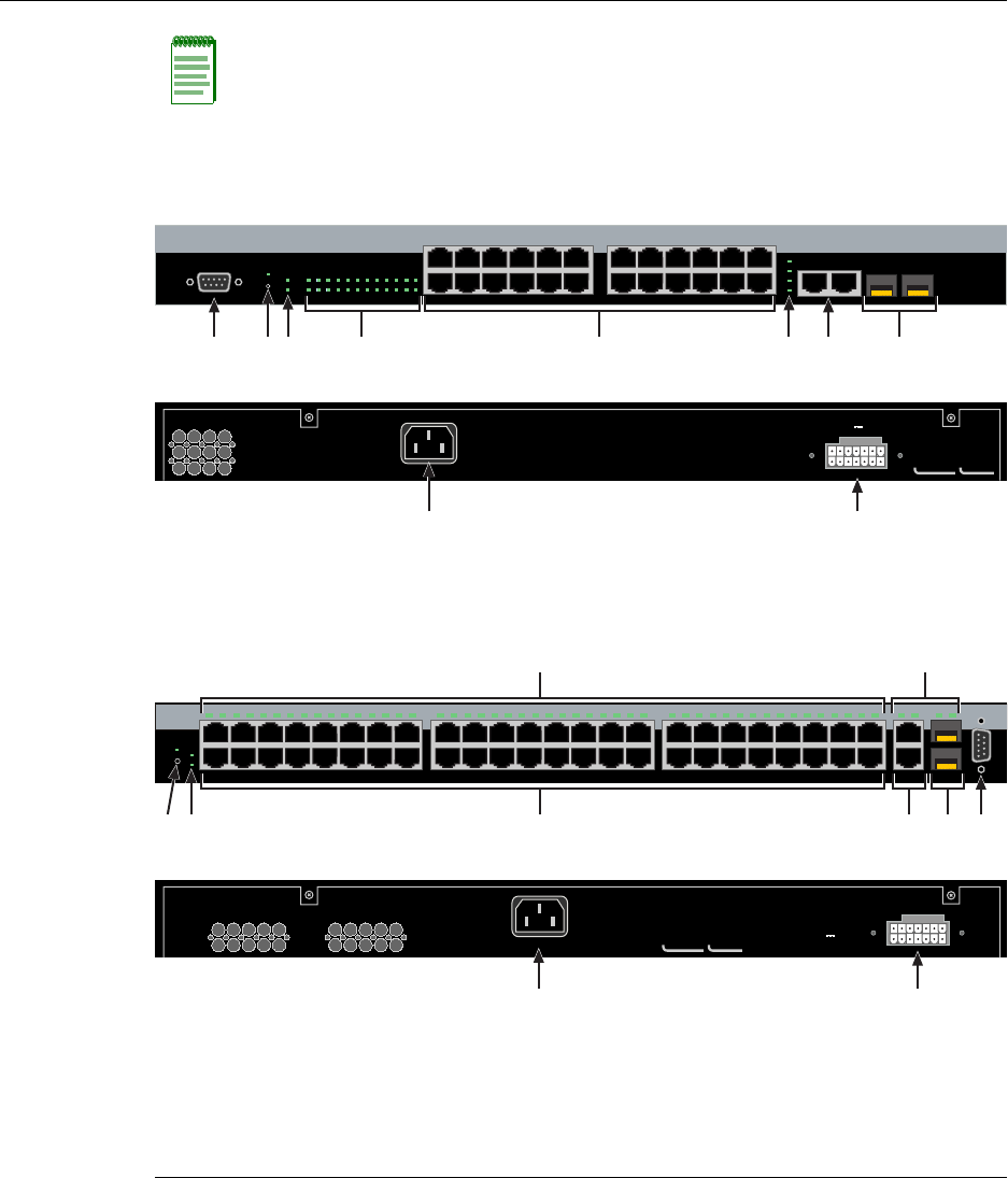
Figure 1-1 A2H124-24P Stackable Switch
Figure 1-2 A2H124-48P Stackable Switch
Note: The 1000BASE-T built-in RJ45 stacking ports 25 and 26 on the A2H124-24P and
ports 49 and 50 on the A2H124-48P can be configured as standard 10/100/1000BASE-T
switch ports, using the command “set switch stackport <ethernet / stack >” when the unit is
used in standalone mode.
1DB9 RS232 Console port connector 6Stack and MGBIC port status LEDs
2Recessed password reset button 7RJ45 ports for stack connections
3Manager and Redundant Power Supply LEDS8SFP interface slots (Mini-GBICs)
4RJ45 port status LEDS9C2RPS-POE connection
5RJ45, 10/100 Mbps ports 10 AC power input connector
AC LINE
100-240 VAC
50-60 Hz
5.1 A MAX.
Redundant Power Supply
DC Line 12V /13A MAX.
MAC ADDRESS SERIAL NO.
1
2
11
12
13
14
23
24
Console
25
26
27
28
25/Up 26/Down
Stack
27 28
1 3 5 7 9 11 13 15 17 19 21 23
2 4 6 8 1012141618202224
CPU
RPS
MGR
A2H124-24P
123456789101112 131415161718192021222324
Ä
È
É
Front
ÇÀ
Back
à ÆÅÁÂ
AC LINE
100-240 VAC
50-60 Hz
1.4 A MAX. Redundant Power Supply
DC Line 12V /13A MAX.
1
2
47
48
15
16
17
18
31
32
33
34
12345678910111213141516 17181920212223242526272829303132 33343536373839404142434445464748
CPU MGR
RPS
49/Up 50/Down 51 52
Console
A2H124-48P
49 51
50 52Stack
Ä
È
É
Front
Æ
Ã
À
Back
Á Â Ç
Å
MAC ADDRESS SERIAL NO.

PoE (Power over Ethernet) Support
1-4 Introduction
Stack Connections
Theswitcheshavefront‐panelRJ45connectorsforconnectionsinastackconfiguration.
ThestackingcablesusedfortheconnectionsarestandardCategory5orbetterUTPcable.
Redundant Power Supply Capability
TheSecureStackA2haspowersupplyredundancycapabilitywhenconnectedtoan
optionalexternalredundantpowersupply(RPS).Iftheinternalpowersupplyfails,the
RPSassumestheentireloadoftheSecureStackA2withoutinterruptingnetworktraffic.
TheinternalpowersupplyandRPSeachhavetheirownACpowerconnection,which
enablestheconnectionofeachpowersupplytoadifferentACpowercircuitfor
additionalACpowersourceredundancy.
PoE (Power over Ethernet) Support
Theswitchis802.3afcompliant,whichmeansitcanprovidepoweroverEthernetcable
connectionsfromitsRJ45frontpanelconnectorstoPDs(powereddevices)inthenetwork.
PoweroverEthernet(PoE)referstotheabilitytoprovide48Vdcpowertoapowered
deviceusingthesameEthernetcablingthatprovidesdata.ModernEthernet
implementationsemploydifferentialsignalsovertwistedpaircables.Thisrequiresa
minimumoftwotwistedpairsforasinglephysicallink.Bothendsofthecableare
isolatedwithtransformersblockinganyDCorcommonmodevoltageonthesignalpair.
PoEexploitsthisfactbyusingtwotwistedpairsasthetwoconductorstosupplyadirect
current.Onepaircarriesthepowersupplycurrentandtheotherpairprovidesapathfor
thereturncurrent.WhileseveralproprietarylegacyimplementationsofPoEhavebeen
deployedbyLANequipmentvendors,in2003theIEEEpublishedtheIEEE802.3af‐2003
specification,whichispartofthe802.3suiteofstandards.
TheswitchisfullycompliantwiththeIEEE802.3afstandard.Itsupportsthestandard
resistor‐baseddetectionmethod,aswellasACdisconnectcapability.Theswitchcan
provideupto360wattsofPoEpowerandiscapableofsupplyingamaximumof15.4
wattstoany10/100port.Inadditionitiscapableofproviding7.5wattsofpowertoall
portssimultaneously.
EachPDhasaPDC(PoweredDeviceClassification)thatistransmittedtotheswitchfor
powermanagementpurposes.Table1‐1liststheclassificationsandtheassociatedpower
ranges.

Connectivity
SecureStack A2 PoE Installation Guide 1-5
Connectivity
TheSecureStackA2connectstoEthernetnetworksorworkstationsviathefixedfront
panelRJ45connectorsandtwouplinkportsthatsupportoptionalMini‐GBICs.
Atthetimeofthisprinting,theMini‐GBICsthatareavailablefromEnterasysand
supportedbyA2switchesaredescribedinTable 1‐2.TheseMini‐GBICsmeetorexceed
theIEEE802.3z‐1998standard.
Table 1-1 Power Device Classifications
Class Usage PD Maximum Power Rang
Usage
None Default 0.44 to 12.95 Watts
1 Optional 0.44 to 3.84
2 Optional 3.84 to 6.49 Watts
3 Optional 6.49 to 12.49 Watts
4 Not Allowed Reserved for Future Use
Table 1-2 Description of Mini-GBICs
Mini-GBIC Specification
MGBIC-LC01 Provides one 1000BASE-SX compliant LC fiber-optic multimode port and a
standard LC connector. For optical and operating range specifications, refer to
“MGBIC-LC01/MGBIC-MT01 Specifications (1000BASE-SX)” on page A-4.
MGBIC-LC03 Provides one 1000BASE-SX Long Haul LC fiber-optic multimode port with a
standard LC duplex connector. For optical and operating range specifications,
refer to “MGBIC-LC03 Specifications (1000BASE-SX)” on page A-5.
MGBIC-LC09 Provides one 1000BASE-LX compliant LC fiber-optic single-mode port with a
standard LC connector. For optical and operating range specifications, refer to
“MGBIC-LC09 Specifications (1000BASE-LX)” on page A-6.
MGBIC-MT01 Provides one 1000BASE-SX compliant LC fiber-optic multimode port with a
standard MT-RJ connector. For optical and operating range specifications, refer
to “MGBIC-LC01/MGBIC-MT01 Specifications (1000BASE-SX)” on page A-4.
MGBIC-08 Provides one 1000BASE-ELX compliant LC fiber-optic single-mode port with a
standard LC connector. For optical and operating range specifications, refer to
“MGBIC-08 Specifications (1000BASE-ELX)” on page A-6.
MGBIC-02 Provides one RJ45 copper connection that is compliant with the 1000BASE-T
standard RJ45 connector. For operating range specifications, refer to
“MGBIC-02 Specifications (1000BASE-T)” on page A-7.

Management
1-6 Introduction
Management
Managementofthemodulecanbeeitherin‐bandorout‐of‐band.In‐bandremote
managementispossibleusingTelnet,Enterasys Networks’NetSight®management
application,ortheWebViewapplication.Out‐of‐bandmanagementisprovidedthrough
theDB9ConsoleportconnectoronthefrontpanelusingaVT100terminaloraVT100
terminalemulator.
Switch Configuration Using WebView
Enterasys Networks’HTTP‐basedWebmanagementapplication(WebView)isan
intuitivewebtoolforsimplemanagementtasks.
Switch Configuration Using CLI Commands
TheCLIcommandsenableyoutoperformmorecompleteSecureStackA2configuration
managementtasks.
ForCLIcommandsetinformationandhowtoconfigurethemodule,refertothe
SecureStackA2ConfigurationGuide.
Standards Compatibility
The100BASE‐Tports arecompliantwiththefollowingstandardsandoperations:
• IEEE802.3
• IEEE802.3u
• IEEE802.3ab(StackPorts)
• IEEE802.3ad
• IEEE802.3af
•Full‐Duplexoperation
Inadditiontotheabovestandards,theSFPportsarecompliantwiththefollowing
standardsandoperations:
• IEEE802.3z
• IEEE802.3xFlowControlsupportforFull‐Duplexmode
•Auto‐negotiationforFull‐Duplexcontroloperations

LANVIEW Diagnostic LEDs
SecureStack A2 PoE Installation Guide 1-7
LANVIEW Diagnostic LEDs
LANVIEWdiagnosticLEDsserveasanimportanttroubleshootingaidbyprovidingan
easywaytoobservethestatusofindividualportsandoverallnetworkoperations.
Getting Help
ForadditionalsupportrelatedtotheSecureStackA2orthisdocument,contact
Enterasys Networksusingoneofthefollowingmethods:
BeforecontactingEnterasys Networksfortechnicalsupport,havethefollowing
informationready:
•YourEnterasys Networksservicecontractnumber.
•Adescriptionofthefailure.
•Adescriptionofanyaction(s)alreadytakentoresolvetheproblem(forexample,
changingmodeorrebootingtheunit.)
•TheserialandrevisionnumbersofallinvolvedEnterasys Networksproductsinthe
network.
•Adescriptionofyournetworkenvironment(forexample,layoutandcabletype)
•Networkloadandframesizeatthetimeoftrouble,ifknown.
•Thedevicehistory(thatis,haveyoureturnedthedevicebefore,isthisarecurring
problem?)
•AnypreviousReturnMaterialAuthorization(RMA)numbers.
World Wide Web www.enterasys.com/services/support/
Phone 1-800-872-8440 (toll-free in U.S. and Canada)
or 1-978-684-1000
For the Enterasys Networks Support toll-free number in your country:
www.enterasys.com/services/support/contact/
Internet mail support@enterasys.com
To expedite your message, type [Switching] in the subject line.
To send comments concerning this document to the Technical Publications Department:
techpubs@enterasys.com
Please include the document Part Number in your email message.

Getting Help
1-8 Introduction
SecureStack A2 PoE Installation Guide 2-1
2
Network Requirements
Beforeinstallingthedevice,reviewtherequirementsandspecificationsinthischapter
concerningthefollowing:
10BASE-T Network
Whenconnectinga10BASE‐TXsegmenttooneoftheRJ45fixedports(1 through24on
A2H124‐24P,1through48onA2H124‐48P),ensurethatthenetworkmeetstheEthernet
networkrequirementsoftheIEEE802.3‐2002standardfor10BASE‐TX.Refertothe
CablingGuidefordetails.
For information about... Refer to page...
10BASE-T Network 2-1
100BASE-TX Network 2-2
1000BASE-FX Network 2-2
1000BASE-T Network 2-2
Note: The network installation must meet the requirements described in this chapter to
ensure satisfactory performance of this equipment. Failure to do so will produce poor
network performance.
Note: The SecureStack A2 Configuration Guide and the Cabling Guide referred to in the
following sections can be found on the Enterasys Networks World Wide Web site:
http://www.enterasys.com/support/manuals
For details about obtaining the manuals, refer to “Related Documents” on page xvi.
Note: If an RJ45 port is to operate at 100 Mbps, Category 5 cabling must be used.
Category 3 cabling does not meet the 100 Mbps specifications. Refer to 100BASE-TX
Network (page 2-2) for information about 100BASE-TX networks and cabling.

100BASE-TX Network
2-2 Network Requirements
100BASE-TX Network
Whenconnectinga100BASE‐TXsegmenttooneofthefixedports(1 through24on
A2H124‐24P,1through48onA2H124‐48P)useCategory5UTPcabling.Thedeviceatthe
otherendofthetwistedpairsegmentmustmeetIEEE802.3‐2002100BASE‐TXFast
EthernetnetworkrequirementsfortheSecureStackA2tooperateat100 Mbps.
1000BASE-FX Network
TheMini‐GBICportsockets(27 and28onA2H124‐24P;51and52onA2H124‐48P)enable
youtovarythetypeof1‐Gbpsportconnection.Attheprintingofthisdocumentthere
weresixsupportedMini‐GBICsavailable,asfollows:
•MGBIC‐LC01fora1000BASE‐SXcompliantLCfiber‐opticmultimodeconnection
•MGBIC‐LC03fora1000BASE‐SXLongHaulLCfiber‐opticmultimodeconnection
•MGBIC‐LC09fora1000BASE‐LXcompliantLCfiber‐opticsingle‐modeconnection
•MGBIC‐MT01fora1000BASE‐SXcompliantMT‐RJfiber‐opticsingle‐mode
connection
•MGBIC‐08fora1000BASE‐ELXcompliantLCfiber‐opticsingle‐modeconnection
•MCBIC‐02fora1000BASE‐TcompliantRJ45copperconnection
ThedeviceattheotherendofthefiberconnectionmustmeetthesameGigabitEthernet
requirementsfortheconnecteddevicestooperateat1‐Gigabitspeed.
1000BASE-T Network
TheRJ45fixedfrontpanelstackingportconnectorssupportRJ45copper1000BASE‐T
compliantconnections.Whenconnectinga1000BASE‐TsegmenttooneoftheRJ45fixed
portsuseCategory5UTPcabling.Instandalonemode,thestackportsmaybeuser
configuredtoserveasastandardswitchport,allowingGigabituplinktothenetwork.The
deviceattheotherendofthetwistedpairsegmentmustmeetIEEE802.3‐2002
1000BASE‐TGigabitEthernetnetworkrequirementsforthedevicestooperateat
1000 Mbps.
Note: When using the RJ45 ports on the SecureStack A2 for 100 Mbps operation use
Category 5 UTP cabling with an impedance between 85 and 111 ohms.
The fixed SecureStack A2 ports are capable of operating at 10 and 100 Mbps. This is
accomplished by the SecureStack A2 when Auto-Negotiation is enabled. This enables the
SecureStack A2 to automatically sense the transmission speed of the other device and
adjust for the speed accordingly.

SecureStack A2 PoE Installation Guide 3-1
3
Hardware Installation
ThischapterprovidesinstructionstoinstalltheA2H124‐24PandA2H124‐48P.Unless
otherwisenoted,theinstructionsapplytoallswitches.Followtheorderofthesections
listedbelowtocorrectlyinstalltheswitch.
Electrical Hazard: Only qualified personnel should perform installation procedures.
Riesgo Electrico: Solamente personal calificado debe realizar procedimientos de
instalacion.
Elektrischer Gefahrenhinweis: Installationen sollten nur durch ausgebildetes und
qualifiziertes Personal vorgenommen werden.
Important Notice
Read the Release Notes shipped with the switch to check for any exceptions to the supported
features and operation documented in this guide.
For information about... Refer to page...
Considerations Prior to Installation 3-2
Required Tools 3-2
Unpacking the Switch 3-2
Installing the Switch on a Flat Surface 3-3
Connecting Stacking Cables 3-7
Configuring Switches in a Stack 3-9
Connecting AC and PoE Power 3-12
Connecting to Console Port for Local Management 3-14
Connecting to the Network 3-19
Installing Optional Mini-GBICs 3-22
Completing the Installation 3-32

Considerations Prior to Installation
3-2 Hardware Installation
Considerations Prior to Installation
Wheninstallingtheswitch,notethefollowing:
•Beforestartingtheinstallationprocedure,notifythenetworkadministratorofthe
installation.
•Followtheinstallationproceduresintheorderaspresentedinthisguide.
•DonotconnecttheswitchtothenetworkuntilyouhaveestablishedthecorrectIP
address.
Required Tools
APhillipsscrewdriverisrequiredtoinstalltheswitchintoarack.
Unpacking the Switch
Unpacktheswitchasfollows:
1. Opentheboxandremovethepackingmaterialprotectingtheswitch.
2. VerifythatthecontentsofthecartoncontainstheitemslistedinTable 3‐1.
3. Removethetapesealonthenon‐conductivebagtoremovetheswitch.
4. Performavisualinspectionoftheswitchforanysignsofphysicaldamage.Contact
Enterasys Networksifthereareanysignsofdamage.Referto“GettingHelp”on
page 1‐7fordetails.
Table 3-1 Contents of Switch Carton
Item Quantity
A2H124-24P or A2H124-48P switch 1
Mounting kit (two mounting brackets and eight M3x6-mm screws for rack mounting) 1
Rubber feet with adhesive backing for installation on a flat surface 4
AC power cord (The type of power cord is country dependent.) 1
This installation guide 1
Customer Release Notes 1
URL notice card 1

Installing the Switch on a Flat Surface
SecureStack A2 PoE Installation Guide 3-3
Installing the Switch on a Flat Surface
Wheninstallingtheswitchonaflatsurface,theinstallationoftherubberfeetis
recommendedtopreventtheswitchfromslidingonaflatsurface.Installingtherubber
feetisoptionalifyouareinstallingtheswitchinarack.Toinstalltherubberfeet,proceed
to“InstallingtheRubberFeet”instructionsbelow.Forinstructionstorackmountthe
switch,proceedto“RackMountingtheSwitch”onpage 3‐6.
Installing the Rubber Feet
Toinstalltherubberfeet,refertoFigure 3‐1andproceedasfollows:
1. Placetheswitchonitsbackonasturdyflatsurfacetogainaccesstothebottomofthe
chassis.
2. Removethefourrubberfeetfromtheirplasticbagintheshippingbox.
3. Locatethefourmarkedlocationsonthebottomfourcornersofthechassis.
4. Removetheprotectivestripfromthebackofonerubberfootandpositionitona
markedlocationandpressfirmlyintoplace.Repeatthisproceduretoinstallthe
remainingthreerubberfeetintheotherthreelocations.
5. Afterinstallingtherubberfeet,returntheswitchtoitsuprightposition.
6. Proceedto“GuidelinesforFlatSurfaceInstallation”onpage 3‐5.Forarackmount
installation,proceedto“RackMountingtheSwitch”onpage 3‐6.
Installing the Switch on a Flat Surface
3-4 Hardware Installation
Figure 3-1 Chassis Bottom, Rubber Feet Placement
1Bottom of chassis as seen when chassis is
resting on its back
3Rubber feet with adhesive backing
(four)
2Locations to install the rubber feet (four locations)
Note: If a number of switches are being installed in a stack, repeat steps 1 through 4 to
install the rubber feet on each switch before continuing with the installation.
À
Á
ÂÂ
ÂÂ
Installing the Switch on a Flat Surface
SecureStack A2 PoE Installation Guide 3-5
Guidelines for Flat Surface Installation
Locatetheswitchwithin152cm(5ft)ofitspowersourceandonasurfaceasshownin
Figure 3‐2.Ifanoptionalredundantpowersystemisgoingtobeinstalledandconnected
tothe14‐pinRedundantPowerSupplyinputconnectorontherearoftheswitch, referto
theinstallationguideshippedwiththeredundantpowersystem.
Ifyouareinstallingseveralswitchesinastack,proceedto“ConnectingStackingCables”
onpage 3‐7.Iftheswitchisbeinginstalledasastandaloneswitch,proceedto“Connecting
ACandPoEPower”onpage 3‐12forpowerconnectioninstructions.
Figure 3-2 Area Guidelines for Switch Installation on Flat Surface
Caution: To ensure proper ventilation and prevent overheating, leave a minimum
clearance space of 5.1 cm (2.0 in.) at the left, right, and rear of the switch.
Do not connect the switch to the AC power source until instructed to do so later in the
installation process.
Precaución: Para asegurar una buena ventilación y evitar que el sistema se
sobrecaliente, deje un espacio mínimo de 5.1 cm (2 pulgadas) con respecto a los lados y
a la parte posterior del aparato.
No conecte el dipositivo a la fuente primaria hasta que no se le indique.
1Approximately 152 cm (5 ft) from power source 344.5 cm (19.4 in.) for proper ventilation
24.45 cm (1.75 in.) per switch. (Vertical clearance
depends on number of switches stacked.)
441.9 cm (16.5 in.) for proper ventilation
À
Á
Ã
Â
1
2
11
12
13
14
23
24
Console
25
26
27
28
25/Up 26/Down
Stack
27 28
1357911131517192123
24681012141618202224
CPU
RPS
MGR
A2H124-24
1 2 3 4 5 6 7 8 9101112 131415161718192021222324
Rack Mounting the Switch
3-6 Hardware Installation
Rack Mounting the Switch
Toinstalltheswitchina19‐inchrack,youneed:
•Tworackmountbracketsandmountingscrews(rackmountkit)shippedwiththe
switch.
•Fouruser‐suppliedscrewstoattachtheswitchtoastandard19‐inchrack.
Guidelines for Rackmount Installation
Theinstallationsitemustbewithinreachofthenetworkcablingandmeetthe
requirementslistedbelow:
• Appropriategroundedpowerreceptaclesmustbelocatedwithin152cm(5ft)ofthe
location.
•Atemperatureofbetween0°C(32°F)and40°C(104°F)mustbemaintainedatthe
installationsitewithfluctuationsoflessthan10°C(18°F)perhour.
Attaching Brackets and Installing in Rack
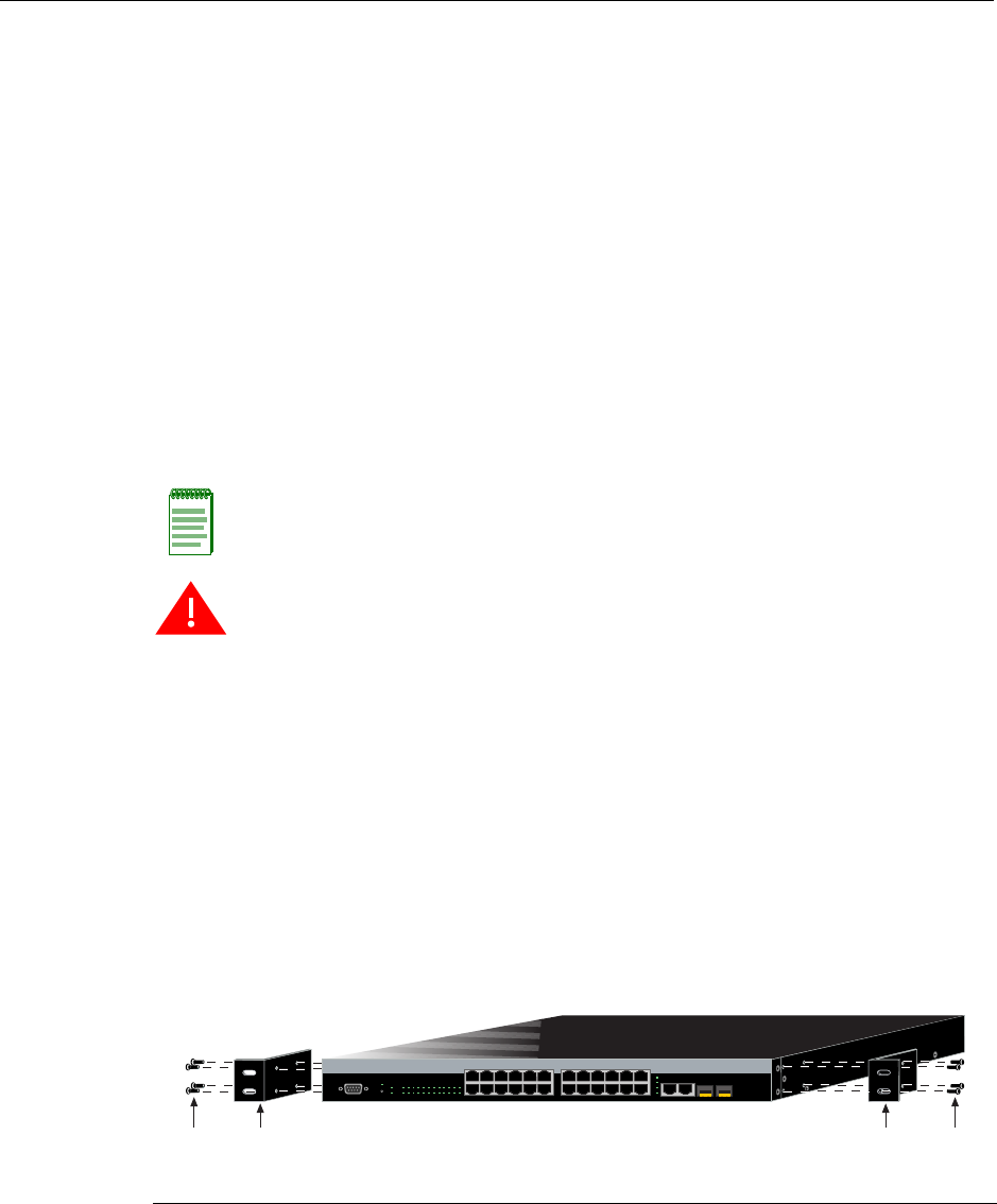
Proceedasfollowstoinstalltheswitchintoa19‐inchrack:
1. Attachtherackmountbracketstotheswitch,asshowninFigure 3‐3,usingtheeight
M3x6mmflatheadscrewsshippedwiththeswitch.
Figure 3-3 Attaching the Rackmount Brackets
Note: To ensure proper ventilation and prevent overheating, leave a minimum clearance
space of 5.1 cm (2.0 in.) at the left, right, and rear of the switch.
Warning: Before rack-mounting the switch, ensure that the rack can support it without
compromising stability. Otherwise, personal injury and/or equipment damage may result.
Advertencia: Antes de montar el equipo en el rack, asegurarse que el rack puede
soportar su peso sin comprometer su propia estabilidad, de otra forma, daño personal o
del equipo puede ocurrir.
Warnhinweis: Überzeugen Sie sich vor dem Einbau des Gerätes in das Rack von dessen
Stabilität, ansonsten könnten Personenschäden oder Schäden am Gerät die Folge sein.
1Rackmount brackets 2M3x6 mm flathead screws
Á
À
Á
À
1
2
11
12
13
14
23
24
Console
25
26
27
28
25/Up 26/Down
Stack
27 28
1 3 5 7 9 11131517192123
2 4 6 8 10 12 14 16 18 20 22 24
CPU
RPS
MGR
A2H124-24P
123456789101112 131415161718192021222324
Connecting Stacking Cables
SecureStack A2 PoE Installation Guide 3-7
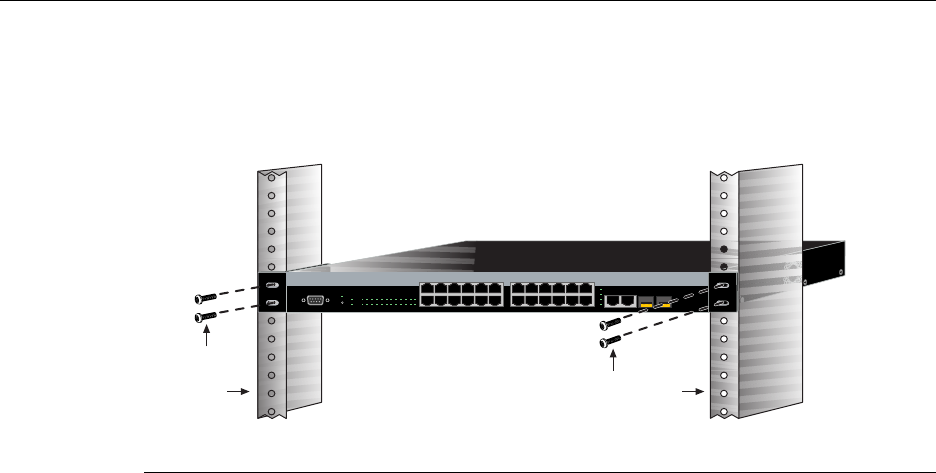
2. Withthemountingbracketsattached,positiontheswitchbetweentheverticalframe
membersofthe19‐inchrackasshowninFigure 3‐4.Thenfastentheswitchsecurely
totheframeusingfourmountingscrews(usersupplied).
Figure 3-4 Fastening the Switch to the Rack
3. Ifyouareinstallingthisswitchinastackedconfiguration,repeatthisprocedurefor
eachswitchuntilallswitcheshavebeeninstalledinthestack,thenproceedto
“ConnectingStackingCables”onpage 3‐7.Otherwise,proceedto“ConnectingAC
andPoEPower”onpage 3‐12.
Connecting Stacking Cables
Thestackofswitchescanbeconnectedinaclosedloopordaisychained.Inaclosedloop
alltheswitchesareconnectedinsequenceandthelastswitchinthestackisconnected
backtothefirstswitch.Inthedaisychainconfigurationthecablethatwouldreturnthe
connectionbacktothefirstswitchinaclosedloopisnotinstalled.Theadvantageofthe
closedloopisredundancy,thisconfigurationeliminatesanysinglepointoffailure.Upto
eightswitchescanbestackedtogetherandconnectedbystandardUTPCategory5or
bettercables.Youcanaddswitchesandreachuptoamaximumof384fixedfrontpanel
portsand16SFPportsforatotalof400Ethernetportsperstack.Thestackingcablesallow
theentirestacktooperatewithasingleIPaddress.
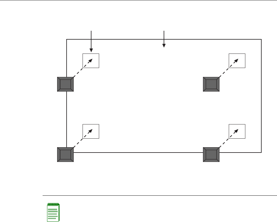
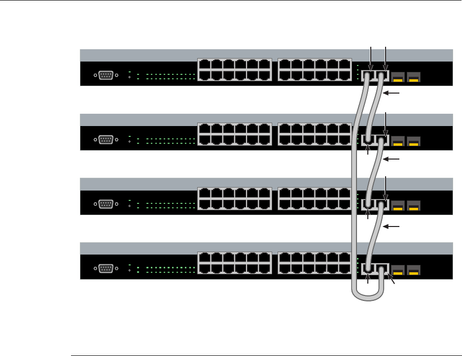
Figure 3‐5showsanexampleofafour‐highstackconnectedinaclosedloop
configuration.AllSTACKDOWNandSTACKUPconnectorsareusedintheinstallation.
ThestackingcableconnectionsarefromtheSTACKDOWNconnectorofoneswitchto
theSTACKUPconnectorofthenextswitchupinthestack.Astackingcableconnection
fromtheSTACKDOWNconnectoroftheswitchatthetopofthestacktotheSTACKUP
connectoratthebottomofthestackclosestheloop.Inadaisychaintopology,onecable
connectionisnotmade.
1Rails of 19-inch rack 2Mounting screws (supplied by user)
Á
À
Á
À
1
2
11
12
13
14
23
24
Console
25
26
27
28
25/Up 26/Down
Stack
27 28
1357911131517192123
24681012141618202224
CPU
RPS
MGR
A2H124-24P
1 2 3 4 5 6 7 8 9 101112 131415161718192021222324
Connecting Stacking Cables
3-8 Hardware Installation
Figure 3-5 Stacking Cable Connections
Afterconnectingthecablestothestackingports,proceedto“ConfiguringSwitchesina
Stack”onpage 3‐9forinstructions.
1Category 5 or better UTP cable 4STACK UP connector at top of stack
2STACK UP connector 5STACK DOWN connector at bottom of stack
3STACK DOWN connector
1
2
11
12
13
14
23
24
Console
25
26
27
28
25/Up 26/Down
Stack
27 28
1357911131517192123
24681012141618202224
CPU
RPS
MGR
A2H124-24P
1 2 3 4 5 6 7 8 9 10 11 12 13 14 15 16 17 18 19 20 21 22 23 24
1
2
11
12
13
14
23
24
Console
25
26
27
28
25/Up 26/Down
Stack
27 28
1357911131517192123
24681012141618202224
CPU
RPS
MGR
A2H124-24P
1 2 3 4 5 6 7 8 9 10 11 12 13 14 15 16 17 18 19 20 21 22 23 24
1
2
11
12
13
14
23
24
Console
25
26
27
28
25/Up 26/Down
Stack
27 28
1357911131517192123
24681012141618202224
CPU
RPS
MGR
A2H124-24P
1 2 3 4 5 6 7 8 9 10 11 12 13 14 15 16 17 18 19 20 21 22 23 24
1
2
11
12
13
14
23
24
Console
25
26
27
28
25/Up 26/Down
Stack
27 28
1357911131517192123
24681012141618202224
CPU
RPS
MGR
A2H124-24P
1 2 3 4 5 6 7 8 9 10 11 12 13 14 15 16 17 18 19 20 21 22 23 24
À
À
À
Á
Á
Á Ä
à Â
Â
Â

Configuring Switches in a Stack
SecureStack A2 PoE Installation Guide 3-9
Configuring Switches in a Stack
TheinformationinthefollowingsectionsisimportanttounderstandA2switchoperation
andinstallationsinastackinstallation.
About SecureStack A2 Switch Operation in a Stack
TheSecureStackA2productsarestackableswitchesthatcanbeadaptedandscaledto
helpmeetyournetworkneeds.Theseswitchesprovideamanagementplatformand
uplinktoanetworkbackboneforastackedgroupofuptoeightA2switches.
Onceinstalledinastack,theswitchesbehaveandperformasasingleswitch.Assuch,
youcanstartwithasingleswitchandaddmoreswitchesasyournetworkexpands.You
canalsomixdifferentproductsinthesamefamilyinasinglestacktoprovideadesired
combinationofporttypesandfunctionstomatchtherequirementsofindividual
applications.Inallcases,astackofswitchesperformsasonelargeproduct,andis
managedasasinglenetworkentity.
Whenswitchesareinstalledandconnectedasdescribedbackin“ConnectingStacking
Cables”onpage 3‐7,thefollowingoccursduringinitialization:
•Theswitchthatwillmanagethestackisautomaticallyestablishedandisreferredtoas
theManagerswitch.
•AllotherswitchesareestablishedasMemberswitchesinthestack.
•Thehierarchyoftheswitchesthatwillassumethefunctionofbackupmanagerisalso
determinedincasethecurrentmanagermalfunctions,ispowereddown,oris
disconnectedfromthestack.
•TheConsoleportonthemanagerswitchremainsactiveforout‐of‐band(local)switch
management,buttheConsoleportoneachmemberswitchisdeactivated.This
enablesyoutosettheIPaddressandsystempasswordusingasingleConsoleport.
Noweachswitchcanbeconfiguredlocallyusingonlythemanager’sConsoleport,or
in‐bandusingaremotedeviceandtheCLIsetofcommandsdescribedinthissection.
ForproceduresusedforvarioustypesofconnectionstotheConsoleport,referto
“ConnectingtoConsolePortforLocalManagement”onpage 3‐14.
Onceastackiscreated(morethanoneswitchisinterconnected),thefollowingoccurs:
1. Switch(unit)IDsarearbitrarilyassignedonafirst‐come,first‐servedbasis.
2. SwitchIDsaresavedagainsteachmodule.Then,everytimeaboardispower‐cycled,
itwillinitializewiththesameswitchID.Thisisimportantforport‐specific
information(forexample:fe.4.12isthe12thFastEthernetportonswitchnumber 4).

Configuring Switches in a Stack
3-10 Hardware Installation
3. Themanagementelectionprocessusesthefollowingprecedencetoassigna
managementswitch:
a. Previouslyassigned/electedmanagementswitch
b. Managementassignedpriority(values1–15)
c. Hardwarepreferencelevel
d. HighestMACAddress
Recommended Procedures for New and Existing Stacks
Installing a New Stackable System of Up to Eight Switches
Usethefollowingproceduretoinstallanewstackofuptoeightswitchesoutofthebox.
Beforeapplyingpower,makeallphysicalconnectionswiththestackcablesasdescribed
in“ConnectingStackingCables”onpage 3‐7.
1. Onceallofthestackcableshavebeenconnected,individuallypoweroneachswitch
fromtoptobottom(connectingpowertoaswitchisdescribedin“ConnectingACand
PoEPower”onpage 3‐12).
Iftheswitchesarepoweredonalmostsimultaneously,thesystemwillautomatically
selectthefirstonethatpowersupastheMasterswitchandtheothersasMember
switches.TheswitchesareassignedunitIDsintheorderthattheybecomefully
operational.
YoucancontroltheunitIDassignmentaccordingtothephysicalpositioninastack.
Whenyoupowerupeachswitchandallowittobecomefullyoperationalbefore
applyingpowertothenextswitch,thefirstonebecomestheManagerandallthenext
switcheswilljointhatstack(regardlessofPriority,FirmwareRevision,orMAC
Address).TheswitchesareassignedunitIDsintheorderthatyoupoweroneach
switch.
2. (Optional)Ifdesired,changethemanagementswitchusingthesetswitch
movemanagementcommandasdescribedintheSecureStackA2ConfigurationGuide.
Important
The following procedures assume that all switches have a clean configuration from manufacturing.
When adding a new switch to an already running stack, it is also assumed that the new switch is
using the same firmware image version as other switches in the stack.
Note: Once switch IDs are assigned, they are persistent and will be retained during a
power cycle to any or all of the switches.

Configuring Switches in a Stack
SecureStack A2 PoE Installation Guide 3-11
3. Oncethedesiredmasterswitchhasbeenselected,thecurrentconfigurationwillbe
savedandthestackwillautomaticallyreset.Youmustnowmovetheconsolecableto
thenewmanagementunit.
4. Stackmembersotherthanthemanagementunitwillonlyidentifytheirunitnumber
throughtheirconsoleport.
5. Persistentdataonallstackunitscanbeclearedalongwiththecurrentconfiguration
usingtheclearconfigallasdescribedintheSecureStackA2ConfigurationGuide.
Adding a New Switch to an Existing Stack
Usethefollowingproceduretoinstallanewswitchtoanexistingstackconfiguration.
Thisprocedureassumesthatthenewswitchbeingaddedhasacleanconfigurationfrom
manufacturingandisrunningthesamefirmwareimageversionasotherswitchesinthe
stack.
1. Ensurethatpowerisoffonthenewswitchbeinginstalled.
2. Useoneofthefollowingmethodstocompletethestackcableconnections:
–Iftherunningstackusesadaisychaintopology,makethestackcableconnections
fromthebottomofthestacktothenewswitch(thatis,STACKDOWNportfrom
thebottomswitchoftherunningstacktotheSTACKUPportonthenewswitch).
–Iftherunningstackusesaclosedloopconfiguration,breaktheloopandmakethe
stackcableconnectionstothenewswitchtoclosetheloop.
3. Applypowertothenewswitch.
Important Considerations About Using Clear Config in a Stack
When using the clear config command (as described in the SecureStack A2 Configuration Guide)
to clear configuration parameters in a stack, it is important to remember the following:
• Use clear config to clear config parameters without clearing stack switch IDs. This command
WILL NOT clear stack parameters and avoids the process of re-numbering the stack.
• Use clear config all when it is necessary to clear all config parameters, including stack switch
IDs and switch priority values.
Connecting AC and PoE Power
3-12 Hardware Installation
Connecting AC and PoE Power
AC Power
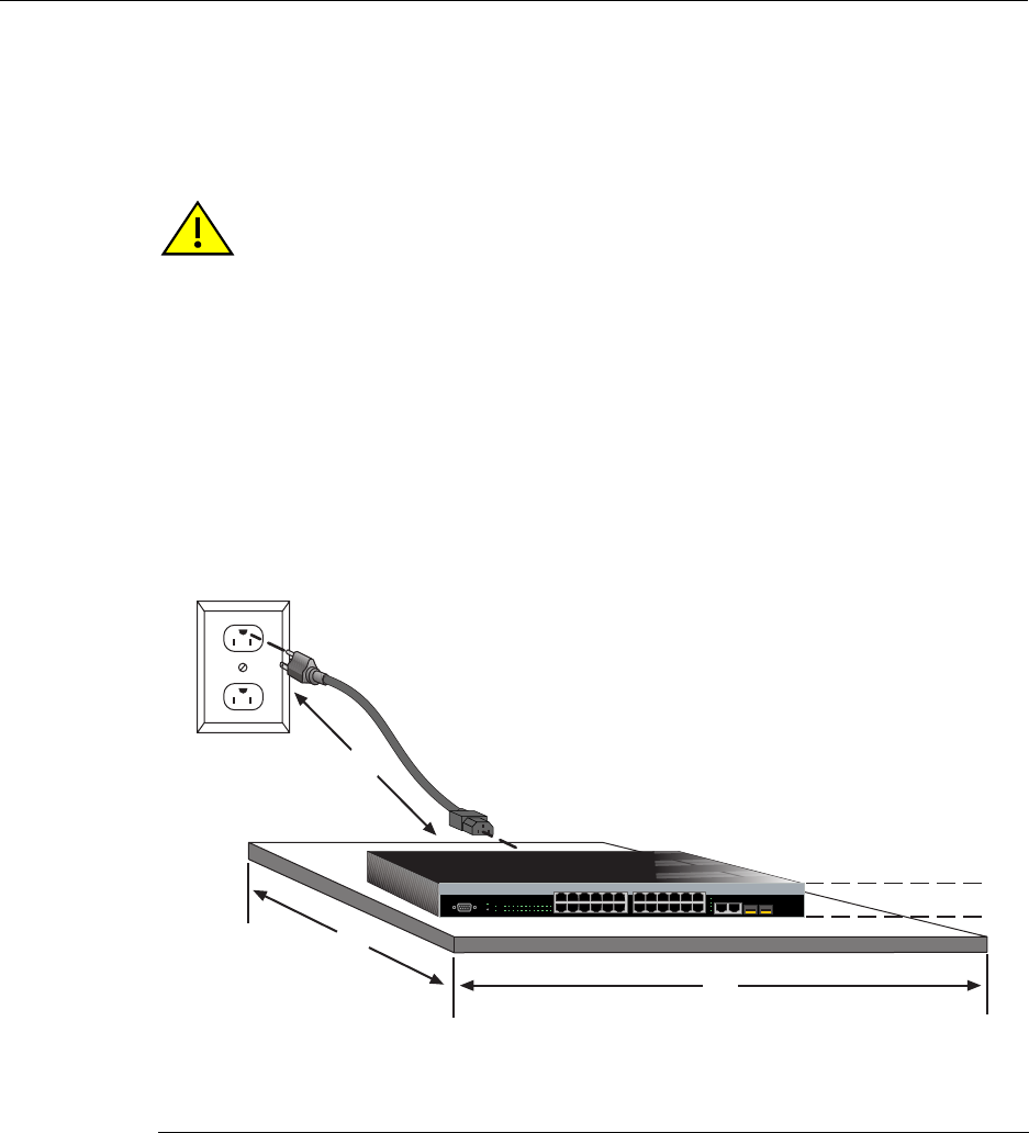
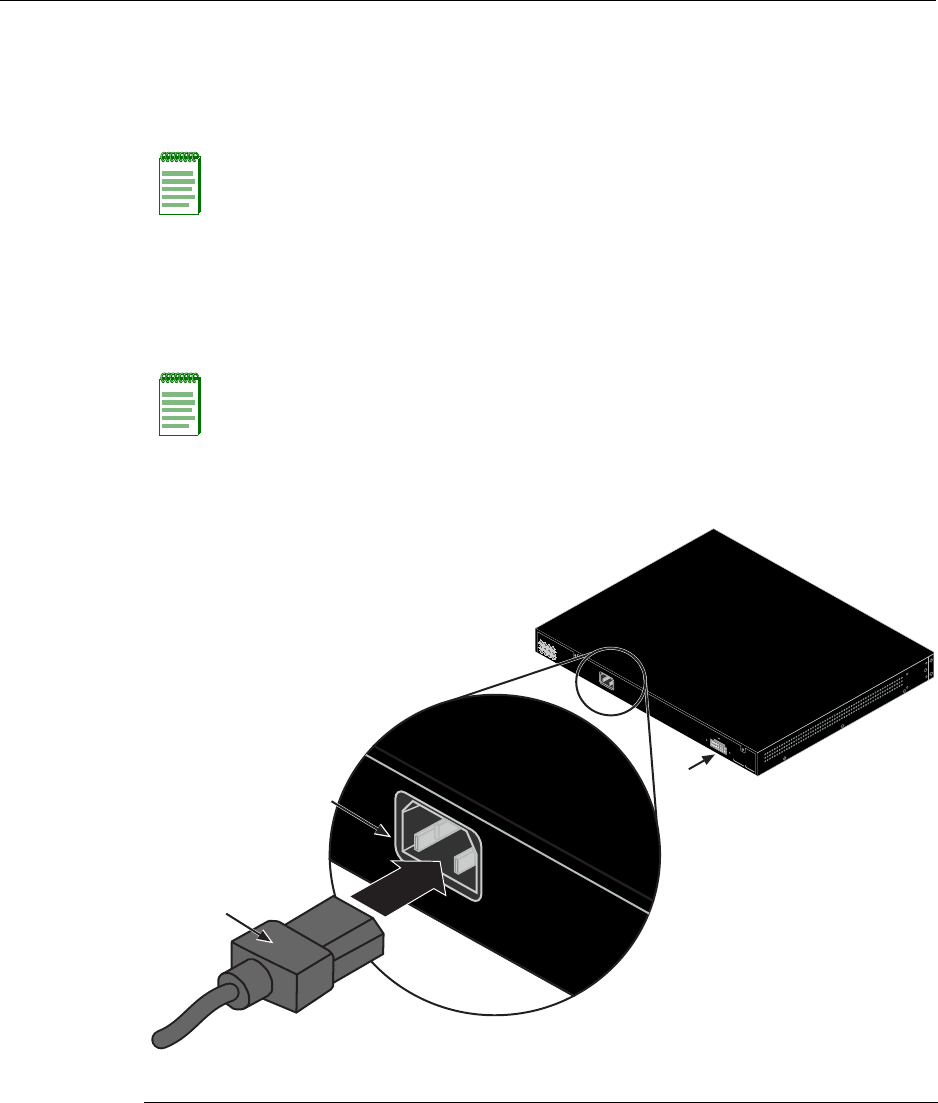
ToconnectaswitchtotheACpowersource,refertoFigure 3‐6andproceedasfollows:
1. Plugthepowercord intotheswitchACpowerconnector.
2. PlugtheotherendofthepowercordintoadedicatedgroundedACoutlet(not
shown).Thetypeofpoweroutletandpowercordarecountry‐dependent.
Figure 3-6 Switch Rear View (A2H124-48P shown)
Note: The power supply in the switch has automatic voltage sensing that allows
connection to power sources ranging from 100 to 240 VAC.
Note: If you plan to connect all the switches quickly to allow automatic Manager selection,
wait until all switches are fully operational before proceeding to the next step.
If you plan to power up each switch and allow it to become fully operational before
applying power to the next switch, proceed to the next step.
1AC power cord 2AC power connector 3Connector for external redundant power supply
AC LINE
100-240 VAC
50-60 Hz
5.1 A MAX.
Redundant Power Supply
DC Line 12V /13A MAX.
MAC ADDRESS SERIAL NO.
AC LINE
100-240 VAC
50-60 Hz
5.1 A MAX.
À
Á
Â
Connecting AC and PoE Power
SecureStack A2 PoE Installation Guide 3-13
3. ObservethepowerCPULED(notshown),locatedonthefrontpanel.Duringthe
initialization,theCPULEDwillstartbyilluminatingsolidamber,thenstartblinking
green,thenblinkingamber,thenblinkinggreenagainuntiltheendofthe
initialization,andthenturnssolidgreen.
Iftheswitchisastandaloneswitch,itwilltakeapproximately30 secondsforthe
switchtostartup.IftheswitchisastackManager,itcantakeupto3minutesormore
tostartup,dependingonthenumberofMemberswitchesinthestack.
C2RPS-PoE Redundant Power System
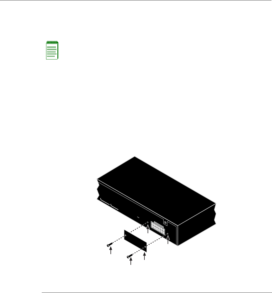
Ifyouareinstallinganoptionalredundantpowersystem(C2RPS‐POE),refertothe
installationinstructionssuppliedwiththeSecureStackC2RPS‐POE.Theswitchis
connectedtoaC2RPS‐POEusingaC2RPS‐POECable.
Figure 3-7 Accessing the RPS connector
Note: If the CPU LED illuminates solid red, there was a critical failure. For more
information about the LED indications and troubleshooting, refer to Chapter 4. If you need
additional help, contact Enterasys Networks. Refer to “Getting Help” on page 1-7 for
details.
1RPS coverplate 3Screw holes for coverplate
2Retaining screws to fasten plate
Redundant Power Supply
DC Line 12V /13A MAX.
MAC ADDRESS SERIAL NO.
À
Á
Á
Â
Â
Connecting to Console Port for Local Management
3-14 Hardware Installation
Ifyouareinstallingtheswitchasastandaloneswitch,proceedto“ConnectingtoConsole
PortforLocalManagement”onpage 3‐14.Ifyouareinstallingswitchesinastack
configuration,applypowertoeachswitchinorder,accordingtotheprocedureyouusein
“ConfiguringSwitchesinaStack”onpage 3‐9.
Stack Initialization Overview
Whenyouinstallandconnectallthestackingcablestotheswitchesinthestackbefore
applyingpowertotheswitches,thefollowingoccurs:
•Theswitchthatwillmanage(Manager)thestackisautomaticallyestablishedwithall
otherswitchesestablishedasMemberswitchesinthestack.Whentheswitches
completetheirinitializations,oneoftheswitchesinthestackwillilluminateits
ManagerLED,indicatingthatitisthestackManager.TheManagerLEDoneach
Memberswitchwillbeoff.
•ThehierarchyoftheswitchesthatwillfunctionasbackupManagerisalsodetermined
incasethecurrentManagermalfunctions,ispowereddown,orisdisconnectedfrom
thestack.
•TheConsoleportoneachMemberswitchwillprovideonlytheunitnumber.Onlythe
ConsoleportontheManagerswitchisactiveandprovidesaCLIforout‐ofband
configurationtosettheIPaddress,password,andothersettings.
OnceyouknowwhichswitchistheManager,proceedto“ConnectingtoConsolePortfor
LocalManagement”onpage 3‐14.
Connecting to Console Port for Local Management
ThissectiondescribeshowtoconnectanRS232DTEinterfacecablefromaPC,aVTseries
terminal,oramodemtoanA2H124‐24PorA2H124‐48Pforout‐of‐bandsessionsusing
CLIcommands.
Caution: To prevent damaging the switch, ONLY connect a Power over
Ethernet-compliant Redundant Power System (C2RPS-POE) to the redundant power
supply connector. The switch is only compatible with the SecureStack C2RPS-POE
redundant power supply system.
Precaución: Conecte una fuente de poder redundante (RPS) SecureStack PoE (C2RPS-
POE) al cable de corriente. De lo contrario, el dispositivo puede dañarse.
Note: When switches are connected in a stack configuration and all stacking cables are
connected before powering up the switches, one switch in the stack will be automatically
designated as the Manager of the stack and its Console port will remain active. All other
switches will become Member switches and their Console ports will be deactivated.
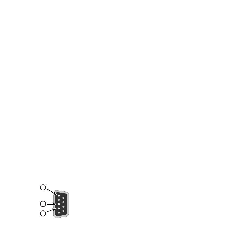
Connecting to Console Port for Local Management
SecureStack A2 PoE Installation Guide 3-15
What Is Needed
Thefollowingisalistofuser‐suppliedDTEinterfacecablesthatmaybeneededtoconnect
theDB9maleConsoleportconnectorontheswitch.ThecablesareterminatedbyaDB9
femaleconnectoratoneend,andbyoneofthreetypeconnectorsattheotherend,
dependingonthetypeconnectionneededfortheremotedevice.Thecablesthatmaybe
neededareasfollows:
•DB9female‐to‐DB9female
•DB9female‐to‐DB25female
•DB9female‐to‐DB25male
UsingaDTEmodemDB9female‐to‐DB9femalecable,youcanconnectproducts
equippedwithaDB9DTEmaleconsoleporttoanIBMorcompatiblePCrunningaVT
seriesemulationsoftwarepackage.
UsingaDTEmodemDB9female‐to‐DB25femalecable,youcanconnectproducts
equippedwithaDB9DTEmaleconsoleporttoaVTseriesterminalorVTtypeterminals
runningemulationprogramsfortheVTseries.
UsingaDTEmodemDB9female‐to‐DB25malecable,youcanconnectproductsequipped
withaDB9DTEmaleconsoleporttoaHayescompatiblemodemthatsupports
9600 baud.
ThecableusedmustconnecttheConsoleportReceivedData,Pin2totheTransmitted
Datapinattheotherendofthecable.TheconnectionfromtheConsoleportTransmitted
Data,Pin3mustbeconnectedtotheReceivedDatapincableconnectionattheotherend
ofthecable.TheDB9ConsoleportpinassignmentsareshowninFigure 3‐8.
Figure 3-8 DB9 Male Console Port Pinout Assignments
1Pin 2, Received Data (input)
2Pin 3, Transmitted Data (output)
3Pin 5, Signal Ground
All other pins not connected.
5
1
9
6
3
2
1
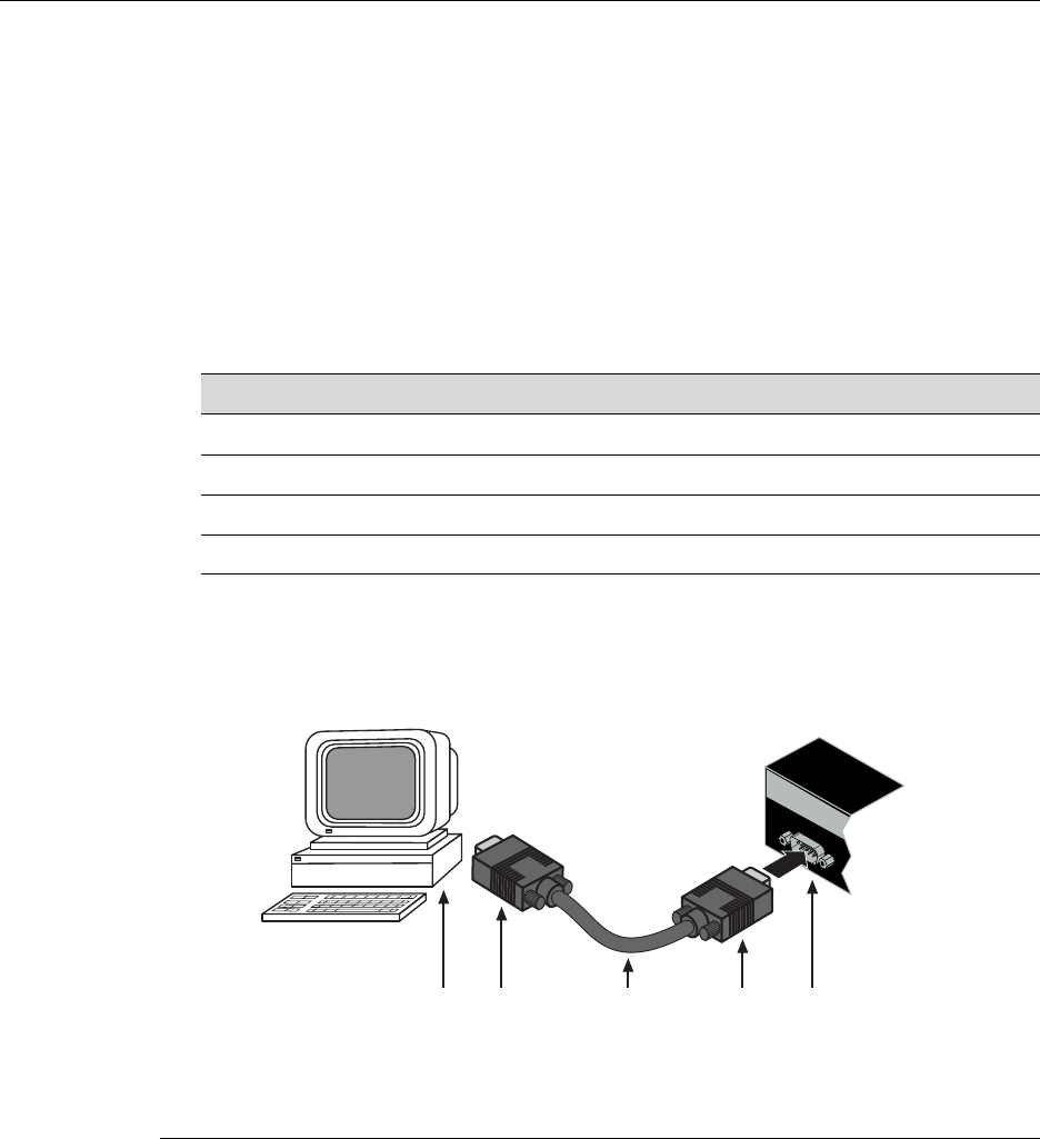
Connecting to Console Port for Local Management
3-16 Hardware Installation
Connecting to an IBM or Compatible Device
ToconnectanIBMPCorcompatibledevice,runningtheVTterminalemulation,toan
EnterasysswitchConsoleport(Figure 3‐9),proceedasfollows:
1. ConnecttheDB9femaleconnectoratoneendofthecable(notsupplied)tothe
ConsoleportontheEnterasysswitch.(IfthereisaswitchdesignatedastheManager,
connecttoitsConsoleport.)
2. PlugtheDB9femaleconnectorattheotherendofcableintothecommunicationsport
onthePC.
3. TurnonthePCandconfigureyourVTemulationpackagewiththefollowing
parameters:
Whentheseparametersareset,theStartupscreenwilldisplay.Proceedto“Connectingto
theNetwork”onpage 3‐19.
Figure 3-9 Connecting an IBM PC or Compatible
Parameter Setting
Mode 7 Bit Control
Transmit Transmit=9600
Bits Parity 8 Bits, No Parity
Stop Bit 1 Stop Bit
1DB9 female connector 4DB9 female connector
2Serial interface cable 5PC with VT emulation application
3DB9 male Console port connector
Console
ÂÃ ÁÀ
Ä
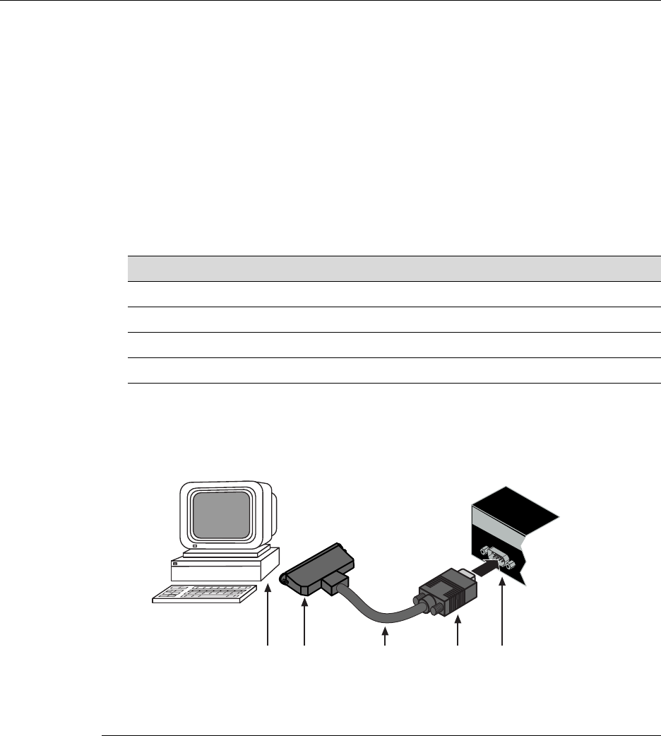
Connecting to Console Port for Local Management
SecureStack A2 PoE Installation Guide 3-17
Connecting to a VT Series Terminal
ToconnectaVTSeriesterminaltoanEnterasysswitchConsoleport(Figure 3‐10),usea
UTPserialinterfacecableterminatedwithaDB9femaleconnectorandaDB25female
connectorandproceedasfollows:
1. ConnecttheDB9femaleconnectoratoneendofcabletotheConsoleportDB9male
connectorontheEnterasysswitch.(IfthereisaswitchdesignatedastheManager,
connecttoitsConsoleport.)
2. PlugtheDB25femaleconnectorattheotherendofthecableintotheportlabeled
COMMontheVTterminal.
3. TurnontheterminalandaccesstheSetupDirectory.Setthefollowingparameterson
yourterminal:
Whentheseparametersareset,theStartupscreenwilldisplay.Proceedto“Connectingto
theNetwork”onpage 3‐19.
Figure 3-10 Connecting a VT Series Terminal
Parameter Setting
Mode 7 Bit Control
Transmit Transmit=9600
Bits Parity 8 Bits, No Parity
Stop Bit 1 Stop Bit
1DB9 female connector 4DB25 female connector
2Serial interface cable 5PC with VT emulation application
3DB9 male Console port connector
ÂÃ ÁÀ
Ä
Console
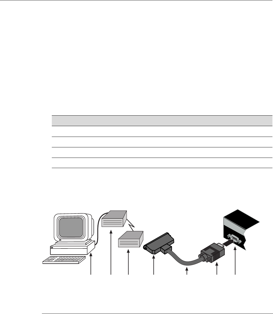
Connecting to Console Port for Local Management
3-18 Hardware Installation
Connecting to a Modem
ToconnectamodemtoanEnterasys Networksswitchconsoleport(Figure 3‐11),usea
UTPcableterminatedwithaDB9femaleconnectorandaDB25maleconnector,and
proceedasfollows:
1. ConnecttheDB9femaleconnectoratoneendofthecabletotheConsoleportDB9
connectorontheEnterasysswitch.(IfthereisaswitchdesignatedastheManager,
connecttoitsConsoleport.)
2. PlugtheDB25maleconnectorattheotherendofthecableintothemodem
communicationsport.
3. TurnonthemodemandmakesuretheremotemodemisON.
4. WithyourPCconnectedtotheremotemodem,configureyourVTemulationpackage
withthefollowingparameters:
Whentheseparametersareset,theStartupscreenwilldisplay.Iftheswitchesareina
stackedconfiguration,proceedto“ConnectingtotheNetwork”onpage 3‐19.
Figure 3-11 Connecting to a Modem
Parameter Setting
Mode 7 Bit Control
Transmit Transmit=9600
Bits Parity 8 Bits, No Parity
Stop Bit 1 Stop Bit
1DB9 female cable connector 4DB25 male connector 7PC with VT emulation application
2Serial interface cable 5Local modem
3DB9 male Console port 6Remote modem
ÂÃ Á À
ÄÅÆ
Console

Connecting to the Network
SecureStack A2 PoE Installation Guide 3-19
Connecting to the Network
Thefollowingprocedurescoverthecableconnectionsfromthenetworkorotherdevices
totheswitchRJ45portsoranyinstalledoptionalMini‐GBIC.
•ConnectingUTPCablesonpage 3‐19
•ConnectingFiber‐OpticCablestoMT‐RJPortsonpage 3‐27
•ConnectingFiber‐OpticCablestoLCPortsonpage 3‐30
Connecting UTP Cables
ThefixedRJ45frontpanelportsare10/100Mbpsportsandhaveautopolaritydetect.
Whenconnectingaworkstationtotheseports,useastraight‐throughcable.When
connectingnetworkingdevicestotheseports,suchasabridge,repeater,orrouter,itisnot
necessarytouseacrossovercable.
Toconnecttwistedpairsegmentstotheswitch,refertoFigure 3‐12andproceedas
follows:
1. Ensurethatthedevicetobeconnectedattheotherendofthesegmentis
powered ON.
2. ConnectthetwistedpairsegmenttotheswitchbyinsertingtheRJ45connectoronthe
twistedpairsegmentintothedesiredRJ45port(forexample,Port8).
Note: All fixed RJ45 front panel ports support Category 5 Unshielded Twisted Pair (UTP)
cabling with an impedance between 85 and 111 ohms. Category 3 cable may be used if
the connection is going to be used only for 10 Mbps.
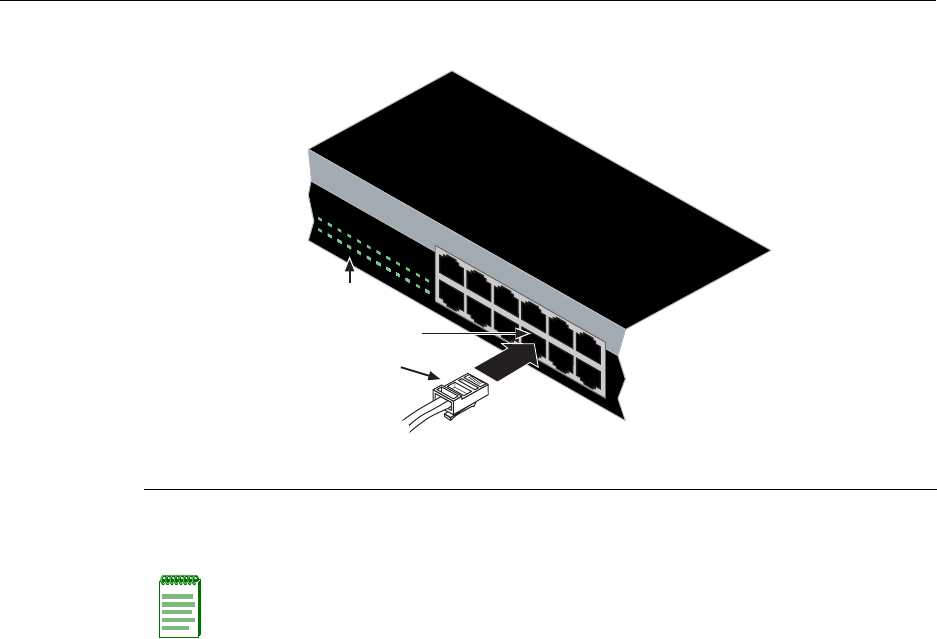
Connecting to the Network
3-20 Hardware Installation
Figure 3-12 Connecting a UTP Cable Segment to RJ45 Port
3. VerifythatalinkexistsbycheckingthattheLink/ActivityLEDisON(solidgreenor
blinkinggreen).
4. IftheLink/ActivityLEDisOFF,performthefollowingstepsuntilitison:
a. VerifythatthecablingbeingusedisCategory 5orbetterwithanimpedance
between85and111 ohmswithamaximumlengthof100meters(328feet).
b. Verifythatthedeviceattheotherendofthetwistedpairsegmentisonand
properlyconnectedtothesegment.
c. VerifythattheRJ45connectorsonthetwistedpairsegmenthavetheproper
pinoutsandcheckthecableforcontinuity.Typically,acrossovercableisused
betweenhubdevicesbutthisisnotnecessary.Astraight‐throughcablecanbe
usedtoconnectbetweentheswitchandanydevice.RefertoFigure 3‐13and
Figure 3‐14forfour‐wireRJ45connections.RefertoFigure 3‐15andFigure 3‐16
foreight‐wireRJ45connections.
d. EnsurethatthetwistedpairconnectionmeetsthedBlossandcablespecifications
outlinedintheCablingGuide.Referto“RelatedDocuments”onpage xvifor
informationonobtainingthisdocument.
5. Ifalinkisnotestablished,contactEnterasys Networks.Referto“GettingHelp”on
page 1‐7fordetails.
Repeatallstepsaboveuntilallconnectionshavebeenmade.
1RJ45 connector 2Port 8 3Port 8 Link/Activity LED
Note: If the cable is connected to one of the PoE RJ45 front panel ports, solid green or
blinking green also indicates that PoE power is available. If the LED is solid amber or
blinking amber PoE power failed. For more details, refer to Chapter 4.
1
2
11
12
1357911 13 1517192123
24681012 14 16 18 20 2224
1234567891011 12
À
Á
Â
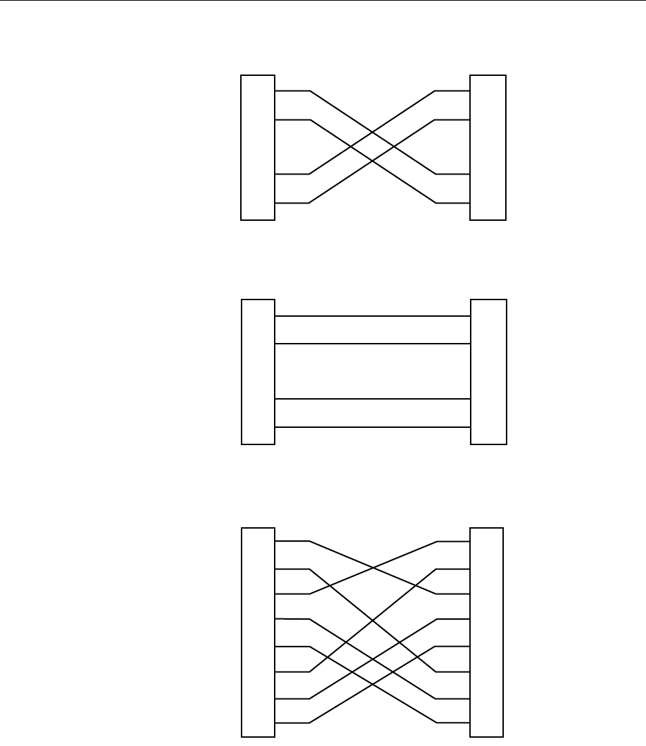
Connecting to the Network
SecureStack A2 PoE Installation Guide 3-21
Figure 3-13 Four-Wire Crossover Cable RJ45 Pinouts for 10/100BASE-TX
Figure 3-14 Four-Wire Straight-Through Cable RJ45 Pinouts for 10/100BASE-TX
Figure 3-15 Eight-Wire Crossover Cable RJ45 Pinouts for 1000BASE-TX
TX+
TX
RX+
RX 2
1
3
6
TX+
TX
2
1
3
6
RX+
RX
MDI MDI-X
TX+
TX
RX+
RX 2
1
3
6
RX+
RX
2
1
3
6
TX+
TX
MDI MDI-X
2
1
3
6
4
5
7
8
TX1+
TX2+
RX4-
RX1-
TX4+
RX3-
TX3+
RX2-
2
1
3
6
4
5
7
8
TX2+
RX4-
RX1-
TX4+
RX3-
TX3+
RX2-
TX1+
MDI MDI
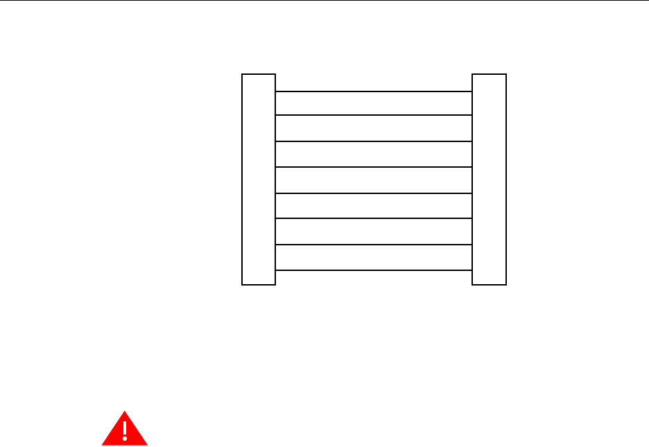
Installing Optional Mini-GBICs
3-22 Hardware Installation
Figure 3-16 Eight-Wire Straight-Through Cable RJ45 Pinouts for 1000BASE-TX
Installing Optional Mini-GBICs
ThissectiondescribeshowtoinstallMini‐GBICsinanyoftheSFPportslots(27and28of
A2H124‐24P;51and52ofA2H124‐48P).Itisrecommendedthattheoptionsbeinstalled
firstinanewinstallation.
TX1+
TX2+
RX4-
RX1-
TX4+
RX3-
TX3+
RX2-
2
1
3
6
4
5
7
8
TX2+
TX1+
RX3-
RX2-
TX3+
RX4-
TX4+
RX1-
2
1
3
6
4
5
7
8
MDI MDI-X
Warning: Fiber-optic Mini-GBICs use Class 1 lasers. Do not use optical instruments to
view the laser output. The use of optical instruments to view laser output increases eye
hazard. When viewing the output optical port, power must be removed from the network
adapter.
Advertencia: Los Mini-GBICS de fibra optica usan lasers de clase 1. No se debe usar
instrumentos opticos para ver la potencia laser. El uso de los instrumentos opticos para
ver la potencia laser incrementa el riesgo a los ojos. Cuando vean el puerto de la potencia
optica, la corriente debe ser removida del adaptador de la red.
Warnhinweis: Mini-GBICs mit Fiber-Optik Technologie benutzen Laser der Klasse 1.
Benutzen sie keinesfalls optische Hilfsmittel, um die Funktion des Lasers zu überprüfen.
Solche Hilfsmittel erhöhen die Gefahr von Sehschäden. Wenn sie den optischen Port
überprüfen möchten stellen Sie sicher, dass die Komponente von der
Spannungsversorgung getrennt ist.

Installing Optional Mini-GBICs
SecureStack A2 PoE Installation Guide 3-23
Preparation
BeforeinstallingtheMini‐GBIC,proceedasfollows:
1. BeforeremovingtheMini‐GBICfromtheantistaticpackaging,itisrecommendedthat
youuseanantistaticwriststrap(notsupplied)topreventdamagefromstatic
discharge.Tousethewriststrap,refertotheinstructionsprovidedwithyour
antistaticwriststrap.
2. RemovetheMini‐GBICfromitspackaging.
3. IfthereisaprotectivedustcoverintheMini‐GBICconnector,donotremoveitatthis
time.
Installation
ToinstallaMini‐GBICthathasanMT‐RJconnector,refertoFigure 3‐18;foraMini‐GBIC
withanLCconnector,refertoFigure 3‐19;foraMini‐GBICwithanRJ45connector,refer
toFigure 3‐17;andproceedasfollows:
1. HoldtheMini‐GBICwiththetopsidepositionedasshown,andthe7‐pinedge
connectorfacingtheportslot.
2. AligntheMini‐GBICwiththeportslot.
3. IfyouareusingtheRJ45Mini‐GBICasinFigure 3‐17,besurethereleasetabisinthe
upposition.
4. PushtheMini‐GBICintotheportslotuntiltheMini‐GBIC“clicks”andlocksinto
place.
Caution: Carefully follow the instructions in this manual to avoid damaging the
Mini-GBIC and the device.
The Mini-GBIC and the device are sensitive to static discharges. Use an antistatic wrist
strap and observe all static precautions during this procedure. Failure to do so could result
in damage to the Mini-GBIC or the switch. Always leave the Mini-GBIC in the antistatic bag
or an equivalent antistatic container when not installed.
Precaución: Siga las instrucciones del manual para no dañar el Mini-GBIC ni del aparato,
puesto que son muy sensible a las descargas de electricidad estática. Utilice la pulsera
antiestática y tome todas las precauciones necesarias durante este procedimiento. Si no
lo hace, podría dañar el Mini-GBIC o del aparato. Mientras no esté instalado, mantenga el
Mini-GBIC en su bolsa antiestática o en cualquier otro recipiente antiestático.
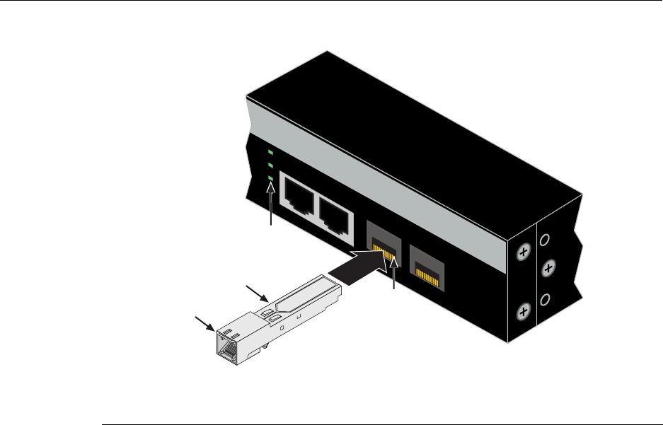
Installing Optional Mini-GBICs
3-24 Hardware Installation
Figure 3-17 Mini-GBIC with RJ45 Connector
1SFP Slot 3Release tab
2Mini-GBIC (MGBIC-02) 4Link/Activity LED
27 28
A2H124-24P
25
26
27
28
25/Up 26/Down
Stack
Â
Á
À
Ã
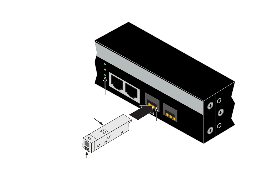
Installing Optional Mini-GBICs
SecureStack A2 PoE Installation Guide 3-25
Figure 3-18 Mini-GBIC with MT-RJ Connector
1SFP Slot 3Release tab
2Mini-GBIC (MGBIC-MT01) 4Link/Activity LED
27 28
A2H124-24P
25
26
27
28
25/Up 26/Down
Stack
Á
À
Ã
Â
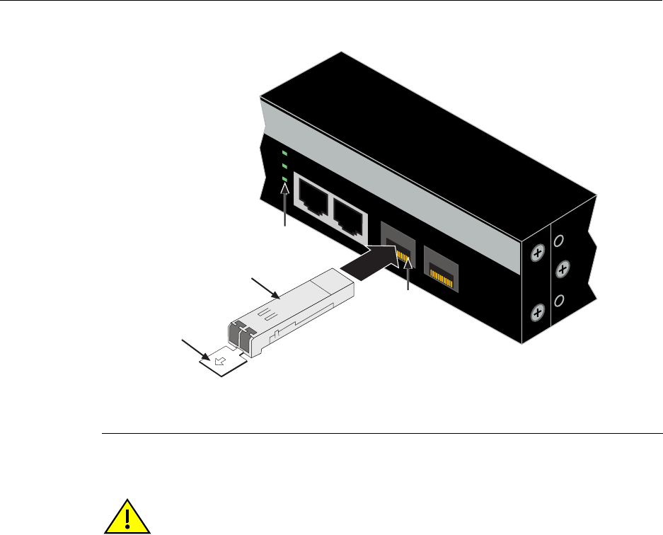
Installing Optional Mini-GBICs
3-26 Hardware Installation
Figure 3-19 Mini-GBIC with LC Connector
Removing the Mini-GBIC
1SFP Slot 3Release tab
2Mini-GBIC (MGBIC-LC01,-LC03, -LC09, MGBIC-08) 4Link/Activity LED
27 28
A2H124-24P
25
26
27
28
25/Up 26/Down
Stack
Â
Á
À
Ã
Caution: Do NOT remove a Mini-GBIC from a slot without releasing the locking tab
located under the front bottom end of the Mini-GBIC. This can damage the Mini-GBIC.
The Mini-GBIC and its host switch are sensitive to static discharges. Use an antistatic wrist
strap and observe all static precautions during this procedure. Failure to do so could result
in damaging the Mini-GBIC or host switch. Always leave the Mini-GBIC in the antistatic
bag or an equivalent antistatic container when not installed.
Precaución: NO quite el Mini-GBIC de la ranura sin antes abrir la traba ubicada en la
parte frontal del Mini-GBIC.
Si lo hace, puede dañar el Mini-GBIC, puesto que es muy sensible a las descargas de
electricidad estática, al igual que el dispositivo host. Utilice la pulsera antiestática y tome
todas las precauciones necesarias durante este procedimiento. Si no lo hace, pude dañar
el Mini-GBIC o el dispositivo host. Mientras no esté instalado, mantenga el Mini-GBIC en
su bolsa antiestática o en cualquier otro recipiente antiestático.

Installing Optional Mini-GBICs
SecureStack A2 PoE Installation Guide 3-27
ToremoveaMini‐GBICfroma portslot,referbacktoFigure 3‐17,Figure 3‐18,and
Figure 3‐19,andproceedasfollows:
1. Attachyourantistaticwriststrap(refertotheinstructionsinyourantistaticwrist
strappackage)beforeremovingtheMini‐GBIC.
2. RemovethecablesconnectedtotheMini‐GBIC.
3. LocatethereleasetabunderthefrontendoftheMini‐GBIC.Forthetypeof
Mini‐GBICshownin:
a. Figure 3‐17,pushdownonthemetalreleasetababovetheconnectorasfarasit
willgotoreleasetheMini‐GBICfromtheportslot.
b. Figure 3‐18,pushinonthereleasetabasfarasitwillgotoreleasetheMini‐GBIC
fromtheportslot.
c. Figure 3‐19,pulloutonthereleasetabtoreleasetheMini‐GBICfromtheportslot.
4. GraspthesidesoftheMini‐GBICandpullitstraightoutoftheportslot.
IfstoringorshippingaMini‐GBIC,whichhasafiber‐opticconnector,insertitsprotective
dustcovertoprotecttheendsofthefiber‐opticfibersfromdustorcontamination.
Connecting Fiber-Optic Cables to MT-RJ Ports
Thissectioncontainstheproceduresforconnectinga1000BASE‐SXmultimodefiber‐optic
segmentfromthenetworkorotherdevicestoanMT‐RJportconnectorinaMini‐GBIC
(MGBIC‐MT01).
Eachfiber‐opticlinkconsistsoftwofiber‐opticstrandswithinthecable:
•Transmit(TX)
• Receive(RX)
Warning: Fiber-optic Mini-GBICs use Class 1 lasers. Do not use optical instruments to
view the laser output. The use of optical instruments to view laser output increases eye
hazard. When viewing the output optical port, power must be removed from the network
adapter.
Advertencia: Los Mini-GBICS de fibra optica usan lasers de clase 1. No se debe usar
instrumentos opticos para ver la potencia laser. El uso de los instrumentos opticos para
ver la potencia laser incrementa el riesgo a los ojos. Cuando vean el puerto de la potencia
optica, la corriente debe ser removida del adaptador de la red.
Warnhinweis: Mini-GBICs mit Fiber-Optik Technologie benutzen Laser der Klasse 1.
Benutzen sie keinesfalls optische Hilfsmittel, um die Funktion des Lasers zu überprüfen.
Solche Hilfsmittel erhöhen die Gefahr von Sehschäden. Wenn sie den optischen Port
überprüfen möchten stellen Sie sicher, dass die Komponente von der
Spannungsversorgung getrennt ist.
Installing Optional Mini-GBICs
3-28 Hardware Installation
Thetransmitstrandfromaswitchportconnectstothereceiveportofafiber‐opticGigabit
Ethernetdeviceattheotherendofthesegment.Thereceivestrandoftheapplicable
MT‐RJportconnectstothetransmitportofthefiber‐opticGigabitEthernetswitch.
Enterasys Networksrecommendslabelingfiber‐opticcablestoindicatereceiveand
transmitends.Manycablesarepre‐labeled,providingmatchinglabelsortapesatboth
endsofeachstrandofcable.
ToconnectanMT‐RJcabletoafixedMT‐RJconnectorofaMini‐GBIC,refertoFigure 3‐20
andproceedasfollows:
1. Removetheprotectivecovers(notshown)fromthefrontpanelMT‐RJfiber‐opticport
(port27inthisexample)andfromtheconnectorsoneachendofthecable.
.
2. InserttheMT‐RJcableconnectorintotheMT‐RJconnectoruntilitclicksintoplace.
Note: Leave the protective covers in place when the connectors are not in use to prevent
contamination.
Caution: Do not touch the ends of the fiber-optic strands, and do not let the ends come in
contact with dust, dirt, or other contaminants. Contamination of cable ends causes
problems in data transmissions. If the ends of the fiber-optic strands become
contaminated, use a canned duster to blow the surfaces clean. A fiber-port cleaning swab
saturated with optical-grade isopropyl alcohol may also be used to clean the ends.
Precaución: No toque los extremos de los cables de fibra óptica y evite su contacto con
el polvo, la suciedad o con cualquier otro contaminante. Si los extremos de los cables se
ensucian, es posible que la transmisión de datos se vea afectada. Si nota que los
extremos de los cables de fibra óptica se ensucian, utilice aire comprimido para limpiarlos.
También puede limpiarlos con un estropajo embebido en alcohol isopropílico.
Note: To remove the MT-RJ cable connector, press on its release tab and pull out the
cable connector.
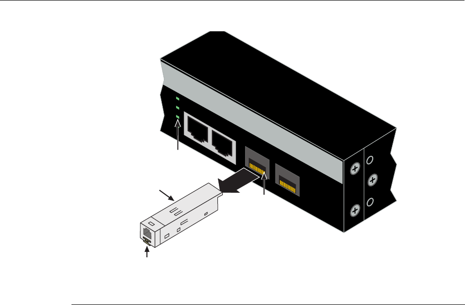
Installing Optional Mini-GBICs
SecureStack A2 PoE Installation Guide 3-29
Figure 3-20 Cable Connection to MT-RJ Multimode Fiber-Optic Connectors
3. Plugtheotherendofthecableintotheappropriateportontheotherdevice.Some
cablesmaybeterminatedattheotherendwithtwoseparateconnectors,oneforeach
fiber‐opticstrand.Inthiscase,ensurethatthetransmitfiber‐opticstrandisconnected
tothereceiveportandthereceivefiber‐opticstrandtothetransmitport.
4. VerifythatalinkexistsbycheckingthattheportLink/ActivityLEDison(blinking
greenorsolidgreen).IftheLink/ActivityLEDisoff,performthefollowingstepsuntil
itison:
a. VerifythatthedeviceattheotherendofthesegmentisONandconnectedtothe
segment.
b. Ifthereareseparatefiber‐opticconnectionsontheotherdevice,checkthe
crossoverofthecables.Swapthecableconnectionsifnecessary.
c. Checkthatthefiber‐opticconnectionmeetsthedBlossandcablespecifications
outlinedintheCablingGuideformultimodecabling.Toobtainthisdocument,
referto“RelatedDocuments”onpage xvi.
Ifalinkhasnotbeenestablished,refertoChapter 4forLEDtroubleshootingdetails.If
aproblempersists,referto“GettingHelp”onpage 1‐7fordetailsoncontacting
Enterasys Networksforsupport.
5. Repeatsteps1through4,above,untilallconnectionshavebeenmade.
1Mini-GBIC MT-RJ port connector 3Release tab
2MT-RJ cable connector 4Link/Activity LED
27 28
A2H124-24P
25
26
27
28
25/Up 26/Down
Stack
Á
À
Ã
Â

Installing Optional Mini-GBICs
3-30 Hardware Installation
Connecting Fiber-Optic Cables to LC Ports
Thissectiondescribeshowtoconnect
•a1000BASE‐SXmultimodefiber‐opticsegmentfromthenetworkorotherdevicesto
anLCportconnectorofaMini‐GBIC(MGBIC‐LC01),or
•a1000BASE‐LXsingle‐modefiber‐opticsegmentfromthenetworkorotherdevicesto
anLCportconnectorofaMini‐GBIC(MGBIC‐LC09).
Eachfiber‐opticlinkconsistsoftwofiber‐opticstrandswithinthecable:
•Transmit(TX)
• Receive(RX)
Thetransmitstrandfromaswitchportconnectstothereceiveportofafiber‐opticGigabit
Ethernetdeviceattheotherendofthesegment.ThereceivestrandoftheapplicableLC
portconnectstothetransmitportofthefiber‐opticGigabitEthernetdevice.
Enterasysrecommendslabelingfiber‐opticcablestoindicatereceiveandtransmitends.
Manycablesarepre‐labeled,providingmatchinglabelsortapesatbothendsofeach
strandofcable.
ToconnectanLCcableconnectortoafixedLCconnectorofaMini‐GBIC,referto
Figure 3‐21andproceedasfollows:
Warning: Fiber-optic Mini-GBICs use Class 1 lasers. Do not use optical instruments to
view the laser output. The use of optical instruments to view laser output increases eye
hazard. When viewing the output optical port, power must be removed from the network
adapter.
Advertencia: Los Mini-GBICS de fibra optica usan lasers de clase 1. No se debe usar
instrumentos opticos para ver la potencia laser. El uso de los instrumentos opticos para
ver la potencia laser incrementa el riesgo a los ojos. Cuando vean el puerto de la potencia
optica, la corriente debe ser removida del adaptador de la red.
Warnhinweis: Mini-GBICs mit Fiber-Optik Technologie benutzen Laser der Klasse 1.
Benutzen sie keinesfalls optische Hilfsmittel, um die Funktion des Lasers zu überprüfen.
Solche Hilfsmittel erhöhen die Gefahr von Sehschäden. Wenn sie den optischen Port
überprüfen möchten stellen Sie sicher, dass die Komponente von der
Spannungsversorgung getrennt ist.
Caution: Do not touch the ends of the fiber-optic strands, and do not let the ends come in
contact with dust, dirt, or other contaminants. Contamination of cable ends causes
problems in data transmissions. If the ends of the fiber-optic strands become
contaminated, use a canned duster to blow the surfaces clean. A fiber-port cleaning swab
saturated with optical-grade isopropyl alcohol may also be used to clean the ends.
Precaución: No toque los extremos de los cables de fibra óptica y evite su contacto con
el polvo, la suciedad o con cualquier otro contaminante. Si los extremos de los cables se
ensucian, es posible que la transmisión de datos se vea afectada. Si nota que los
extremos de los cables de fibra óptica se ensucian, utilice aire comprimido para limpiarlos.
También puede limpiarlos con un estropajo embebido en alcohol isopropílico.
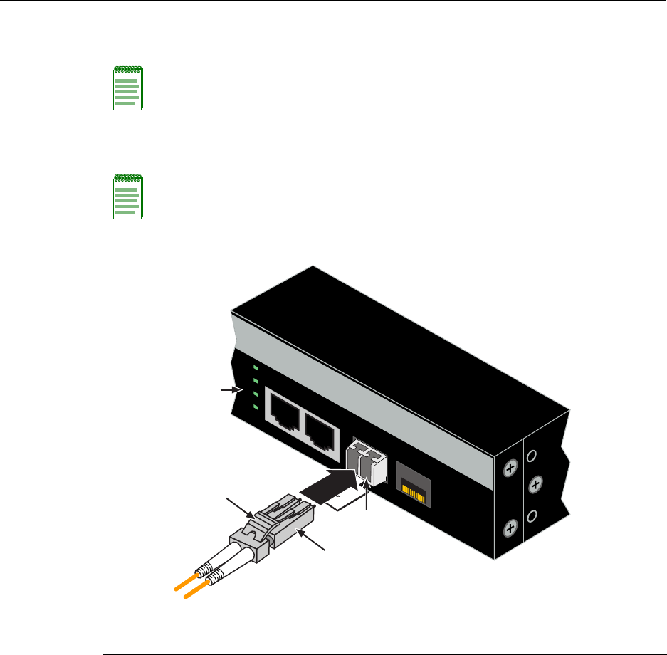
Installing Optional Mini-GBICs
SecureStack A2 PoE Installation Guide 3-31
1. Removetheprotectivecovers(notshown)fromthefrontpanelLCfiber‐opticport
(port27inthisexample)andfromtheconnectorsoneachendofthecable.
2. InserttheLCcableconnectorintotheMini‐GBICLCconnectoruntilitclicksinto
place.
Figure 3-21 Cable Connection to LC Fiber-Optic Connectors
3. Plugtheotherendofthecableintotheappropriateportontheotherdevice.Some
cablesmaybeterminatedattheotherendwithtwoseparateconnectors,oneforeach
fiber‐opticstrand.Inthiscase,ensurethatthetransmitfiber‐opticstrandisconnected
tothereceiveportandthereceivefiber‐opticstrandtothetransmitport.
Note: Leave the protective covers in place when the connectors are not in use to prevent
contamination.
Note: To remove the LC cable connector, press on its release tab and pull it out of
Mini-GBIC LC connector.
1Mini-GBIC MT-RJ port connector 3Release tab
2LC cable connector 4Link/Activity LED
27 28
A2H124-24P
Ã
À
Â
Á
25
26
27
28
25/Up 26/Down
Stack

Completing the Installation
3-32 Hardware Installation
4. VerifythatalinkexistsbycheckingthattheportLink/ActivityLEDison(blinking
greenorsolidgreen).IftheLink/ActivityLEDisoff,performthefollowingstepsuntil
itison:
a. VerifythatthedeviceattheotherendofthesegmentisONandconnectedtothe
segment.
b. Ifthereareseparatefiber‐opticconnectionsontheotherdevice,checkthe
crossoverofthecables.Swapthecableconnectionsifnecessary.
c. Checkthatthefiber‐opticconnectionmeetsthedBlossandcablespecifications
outlinedintheCablingGuideformultimodemodecabling.Toobtainthis
document,referto“RelatedDocuments”onpage xvi.
d. Ifalinkhasnotbeenestablished,refertoChapter 4forLEDtroubleshooting
details.Ifaproblempersists,refertoreferto“GettingHelp”onpage 1‐7for
detailsoncontactingEnterasys Networksforsupport.
5. Repeatsteps1through4,above,untilallconnectionshavebeenmade.
Completing the Installation
Afterinstallingtheswitchandmakingtheconnectionstothenetwork,accesstheswitch
management,asdescribedbelow.
Initial Logon to Switch Management
ToinitiallyaccessswitchmanagementfromyourlocalPC,terminal,ormodem
connection,proceedasfollowsatthedisplayedstartupscreen:
1. Enterrw(Read‐Write)oradmin(superuser)forUsername.
2. AtthePasswordprompt,pressEnter(RETURN).
3. Fordetailsonhowtoconfiguretheswitchusingthecommandlineinterface,referto
theSecureStackA2ConfigurationGuide.TheCLIcommandsenableyoutosetanew
passwordandperformmoreinvolvedmanagementconfigurationsontheswitch.
Oneofmanycapabilitiesistoreconfigurethestack,reassigningtheManagerfunction
toanotherswitchandconfiguringtheorderofMemberswitchesthatwilltakeover
thestackmanagementfunctionsincasetheoperatingManagerispowereddown,
malfunctions,orisremovedfromthestack.
4. Aftertheinitialconfiguration,youcanalsouseWebView(Enterasys Networks’
embeddedwebserver)forconfigurationandmanagementtasks.
Alltheguidesassociatedwiththeswitchareavailableonlineat:
http://www.enterasys.com/support/manuals
Onceyouareconfidentthattheinstallationissuccessful,routeandsecureyourcables.If
yourequireassistance,contactEnterasysNetworksusingoneofthemethodsdescribedin
“GettingHelp”onpage 1‐7.
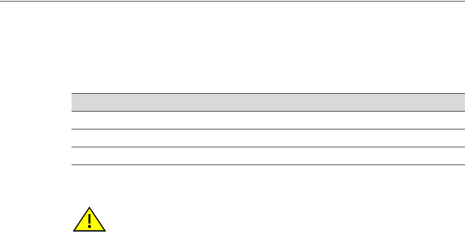
SecureStack A2 PoE Installation Guide 4-1
4
Troubleshooting
Thischapterprovidesinformationconcerningthefollowing:
Thisdevicecontainsabatterythatisnotconsideredauserreplaceablepart.Ifthebattery
needstobereplaced,contactcustomerserviceforrepair.
For information about... Refer to page...
Using LANVIEW 4-2
Troubleshooting Checklist 4-7
Using the Reset Password Switch 4-9
Caution: There is a risk of explosion if the battery is replaced with an incorrect type. A
used battery may be safely disposed in a municipal waste stream.
Precaucion: Hay riesgo de explosion si la bateria se reemplaza con el typo incorrecto.
Puede tirar la bateria usada en la basura.
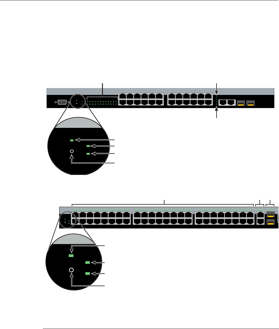
Using LANVIEW
4-2 Troubleshooting
Using LANVIEW
TheseswitchessupporttheEnterasys Networksbuilt‐inLANVIEWLEDvisual
diagnosticandstatusmonitoringsystem.TheLANVIEWLEDsonboththeA2H124‐24P
andA2H124‐48ParelocatedinsimilarlocationsasshownonA2H124‐24PinFigure 4‐1.
TheLANVIEWLEDsontheA2H124‐48PareshowninFigure 4‐2.TheseLEDsallowyou
toquicklyobservenetworkstatusfordiagnosingswitchandnetworkproblems.
Figure 4-1 LANVIEW LEDs of A2H124-24P
Figure 4-2 LANVIEW LEDs of A2H124-48P
1Recessed Password Reset switch 510/100 Mbps Ports Link/Activity
2Redundant Power Supply Active 61000 Mbps Stacking Port Link/Activity
3Unit selected as Stack Manager 7Mini-GBIC Link/Activity
4CPU and Power Indicator
1
2
11
12
13
14
23
24
Console
25
26
27
28
25/Up 26/Down
Stack
27 28
1 3 5 7 9 11 13 15 17 19 21 23
2 4 6 8 1012141618202224
CPU
RPS
MGR
A2H124-24P
123456789101112 131415161718192021222324
Ä Å
Á
Â
Ã
À
CPU
RPS
MGR
Æ
1
2
47
48
15
16
17
18
31
32
33
34
1 2 3 4 5 6 7 8 9 10 11 12 13 14 15 16 17 18 19 20 21 22 23 24 25 26 27 28 29 30 31 32 33 34 35 36 37 38 39 40 41 42 43 44 45 46 47 48
CPU MGR
RPS
49/Up 50/Down 51 52
C
A2
49 51
50 52Stack
Ä
Å
CPU MGR
RPS
Æ
Á
Â
Ã
À

Using LANVIEW
SecureStack A2 PoE Installation Guide 4-3
Note: The terms flashing, blinking, and solid used in Tab le 4 - 1 indicate the following:
Flashing: LED is flashing randomly.
Blinking: LED is flashing at a steady rate (approximately 50% on, 50% off).
Solid: LED is on steady and not pulsing.
Table 4-1 LANVIEW LEDs
LED Color State Recommended Action
CPU Off Power disconnected. If the LED remains off after connecting AC
power or DC power from an RPS, check
the following:
1. Make sure there is power at the power
source (AC source and RPS if
applicable).
2. Replace the power cord with a known
good one or check the continuity of the
power cord.
3. If the SecureStack A2 still does not
power up, the system may have a fatal
error. Contact Enterasys Networks for
technical support.
Red Solid. Boot-up failed. If the LED remains red for several
minutes, the system may have a fatal
error. Contact Enterasys Networks for
technical support.
Blinking. Diagnostics have
failed.
Contact Enterasys Networks for technical
support.
Amber Solid. Diagnostics are running. If the LED remains amber for more than
several minutes, contact
Enterasys Networks for technical support.
Blinking. Code image is being
downloaded.
This also notes when the
configuration is being saved to
member units. (This occurs
every 15 minutes and when the
user enters the “save config”
command).
None.
Green Solid. System is fully
functional.
None.
Blinking. Boot-up in process. None.

Using LANVIEW
4-4 Troubleshooting
DOWN Off No valid connection to switch
stackup connector.
1. Make sure the switch connected to the
stackup connector is powered on.
2. Replace cable with a known good one.
3. If the problem still exists, contact
Enterasys Networks for technical
support.
Green Solid. Valid connection to
switch stackup connector.
Flashing. Information is being
transferred via the stacking
cable.
None.
UP Off No valid connection to switch
stackdown connector.
1. Make sure the switch connected to the
stackdown connector is powered on.
2. Replace cable with a known good one.
3. If the problem still exists, contact
Enterasys Networks for technical
support.
Green Solid. Valid connection to
switch stackdown connector.
Flashing. Information is being
transferred via the stacking
cable.
None.
Manager Off Switch is operating as a
Member in the stack.
None.
Green Solid. Switch is operating as
the Manager of the stack.
None.
Table 4-1 LANVIEW LEDs (continued)
LED Color State Recommended Action

Using LANVIEW
SecureStack A2 PoE Installation Guide 4-5
RPS Off The RPS LED remains off
regardless if the RPS is
attached or not. The LED being
in its off state is not an
indication that the RPS is not
functioning properly and won’t
supply power in the event of an
AC power supply failure.
See Amber state below.
None.
Amber Solid.The switch internal
power supply failed, and the
RPS is providing the proper
power to the switch.
1. Ensure that the AC power cord is
plugged in correctly and that there is
power at the AC power source.
2. Replace the power cord with a known
good one.
3. If the problem persists, contact
Enterasys Networks for technical
support.
Link
Activity
Off 1. No link - no connection.
2. Remote device powered off.
3. Port in standby.
4. Cable is bad.
None.
Power on remote device.
Use CLI to enable port.
Replace UTP cable with a known good
one.
Green Solid. Port is linked, but the
interface is not receiving any
traffic.
None.
Blinking. Port is linked and
traffic is being received or
transmitted by the interface.
None.
Table 4-1 LANVIEW LEDs (continued)
LED Color State Recommended Action

Using LANVIEW
4-6 Troubleshooting
Amber Solid. Port is linked, but traffic
is not being received or
transmitted by the interface.
PoE power has failed.
PoE power may have been
deactivated because of
excessive power requirement
or deactivated by
configuration.
Power Supply failed.
1. Check the attached powered device to
see if it is defective.
2. Internal power supply failed, contact
Enterasys Networks for technical
support.
Blinking. Port is linked and
traffic is being received or
transmitted by the interface.
PoE power has failed.
PoE power may have been
deactivated because of
excessive power requirement
or deactivated by
configuration.
Power supply failed.
1. Check the attached powered device to
see if it is defective.
2. Internal power supply failed, contact
Enterasys Networks for technical
support.
Table 4-1 LANVIEW LEDs (continued)
LED Color State Recommended Action

Troubleshooting Checklist
SecureStack A2 PoE Installation Guide 4-7
Troubleshooting Checklist
Ifthedeviceisnotworkingproperly,refertoTable 4‐2forachecklistofproblems,
possiblecauses,andrecommendedactionstoresolvetheproblem.
Table 4-2 Troubleshooting Checklist
Problem Possible Cause Recommended Action
All LEDs are OFF. Loss of power. Ensure that the SecureStack A2 was
installed properly according to the
installation instructions in Chapter 3.
Ensure that the power cords are
connected properly to an active power
source that meets the AC input
specifications for this switch.
Ensure that the AC power cord is not
damaged. Replace the power cord with a
known good one.
All LEDs are OFF Possible mismatch in code
between the master and the
device. If the switch does not
have the same code as the
stack master the switch will not
join the stack and all LEDs will
remain off.
Connect to the console port and type
“show switch”. If a code mismatch is the
cause, the output of the above command
will show “code version mismatch”.
Disconnect the switch from the stack and
load the necessary code to match the
stack master.
No local
management
startup screen.
Incorrect terminal setup. Refer to the SecureStack A2
Configuration Guide for proper setup
procedures.
Improper Console cable
pinouts.
Refer to Appendix A for proper Console
port pinouts.
Corrupt firmware image, or
hardware fault.
If possible, attempt to download the image
to the device again. Refer to the
SecureStack A2 Configuration Guide for
details.
Cannot navigate
beyond startup
screen.
Improper Community Names
Tabl e.
Refer to the SecureStack A2
Configuration Guide for the Community
Names Table setup.

Troubleshooting Checklist
4-8 Troubleshooting
Cannot contact the
SecureStack A2
through in-band
management.
IP address not assigned. Refer to the SecureStack A2
Configuration Guide for the IP address
assignment procedure.
Port is disabled. This is normal if the switch is a Member in
a stack.
If operating as a standalone switch or as
the Manager in a stack, enable the port.
Refer to the SecureStack A2
Configuration Guide for instructions to
enable/disable ports.
No link to switch. Verify that all network connections
between the network management station
and the device are valid and operating.
If the problem continues, contact
Enterasys Networks for technical support.
Port(s) goes into
standby for no
apparent reason.
Loop condition detected. Verify that Spanning Tree is enabled.
Refer to the SecureStack A2
Configuration Guide for the instructions to
set the type of STA.
Review the network design and delete
unnecessary loops.
If the problem continues, contact
Enterasys Networks for technical support.
User parameters (IP
address, switch and
module name, etc.)
were lost when the
SecureStack A2
power was cycled.
Clear NVRAM was set using
CLI commands.
Reenter the lost parameters as
necessary. Refer to the SecureStack A2
Configuration Guide for the instructions to
configure the SecureStack A2 using CLI
commands.
If the problem continues, contact
Enterasys Networks for technical support.
User powered the switch off
before the configuration was
saved (configuration changes
on the A2 are internally saved
every two minutes).
Execute the “save config” command, and
wait for the prompt to come back before
Powering the switch off.
Executing the “reset” command
automatically saves the config before
resetting the switch.
Table 4-2 Troubleshooting Checklist (continued)
Problem Possible Cause Recommended Action
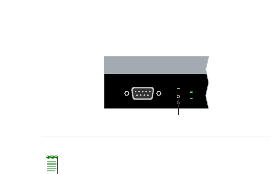
Using the Reset Password Switch
SecureStack A2 PoE Installation Guide 4-9
Using the Reset Password Switch
IfyouforgettheSecureStackA2loginpassword,usetheResetpasswordswitchas
describedinthefollowingprocedure.
Figure 4-3 Reset Password Switch
ToresettheSecureStackA2password,refertoFigure 4‐3andproceedasfollows:
1. Press‐and‐holdtheResetPasswordswitchwhiletheswitchisoperational.This
changeoftheloginpasswordtothedefaultpasswordwillbeindicatedviaLocal
ManagementCLIonly.ThisinformationwillnotshowupinaTelnetsession.
2. Logontoswitchmanagement.YoucannowlogontotheswitchviatheConsoleport
andassignanewpasswordusingthecommandlineinterface(CLI).
3. ToaccessswitchmanagementfromyourlocalPC,terminal,ormodemconnection,
refertotheSecureStackA2ConfigurationGuideforinstructionsonhowtologinand
enteranewpassword.TheguideisavailableonlineundertheScategoryfor
Securestackat:
http://www.enterasys.com/support/manuals
Ifyourequireassistance,contactEnterasysNetworksusingoneofthemethodsdescribed
in“GettingHelp”onpage 1‐7.
1Reset password switch
Note: Notify the system manager before changing the password.
Console
CPU
RPS
MGR
À

Using the Reset Password Switch
4-10 Troubleshooting

SecureStack A2 PoE Installation Guide A-1
A
Specifications
Thisappendixprovidesinformationaboutthefollowing:
Enterasys Networksreservestherighttochangethespecificationsatanytimewithout
notice.
Switch Specifications
Table A‐1providestheI/Oports,processorsandmemory,physical,andenvironmental
specificationsfortheA2H124‐24P.
Table A‐2providestheI/Oports,processorsandmemory,physical,andenvironmental
specificationsfortheA2H124‐48P.
For information about... Refer to page...
Switch Specifications A-1
Mini-GBIC Input/Output Specifications A-4
Gigabit Ethernet Specifications A-4
MGBIC-02 Specifications (1000BASE-T) A-7
Regulatory Compliance A-8
Table A-1 A2H124-24P Switch Specifications
Item Specification
RJ45 ports 1 through 24 Twenty-four 10/100BASE-T compliant ports with auto-sensing
and auto-negotiation via RJ45 UTP connectors.
RJ45 ports 25 and 26 Two 10/100/1000BASE-TX compliant ports with auto-sensing
and auto-negotiation via RJ45 UTP connectors for stacking. In
standalone mode, these ports can be used for host connections
and interswitch links.
SFP ports 27 and 28 Two slots that support optional Mini-GBICs 1000BASE-FX
fiber-optic connections and 1000BASE-T copper connections.

Switch Specifications
A-2 Specifications
AC Input Specifications
Input Voltage 100 to 240 VAC
Input Currrent 5.1 A Max
Frequency 50 to 60 Hz
Processors/Memory
Processor MPC8241, 266 MHz processor
Dynamic Random Access
Memory (DRAM)
128 MB
FLASH Memory 16 MB
Physical
Dimensions 4.4 H x 44.1 W x 21.0 D cm (1.7 H x 17.4 W x 8.27 D in.)
Approximate Weight Gross:
Net:
6.8 kg (14.99 lb) (shipping carton
containing one module)
5.78 kg (12.74 lb) (one module
without packaging)
Predicted hours for Mean Time
Between Failures (MTBF)
201,377 hours
Heat Dissipation (maximum) @ 29.01 W, 1522 Btu/hr
Environmental
Operating Temperature 0°C to 40°C (32°F to 104°F)
Storage Temperature -40°C to 70°C (-40°F to 158°F)
Operating Relative Humidity 5% to 95% (non-condensing)
Table A-1 A2H124-24P Switch Specifications (continued)
Item Specification

Switch Specifications
SecureStack A2 PoE Installation Guide A-3
Table A-2 A2H124-48P Switch Specifications
Item Specification
RJ45ports 1 through 48 Forty-eight 10/100BASE-T compliant ports with auto-sensing
and auto-negotiation via the RJ45 connections.
RJ45ports 49 and 50 Two 10/100/1000BASE-TX compliant ports with auto-sensing
and auto-negotiation via RJ45 connectors for stacking. In
standalone mode, these ports can be used for host connections
and interswitch links.
SFP ports 51 and 52 Two slots that support optional Mini-GBICs for 1000BASE-T
Gigabit copper and 1000BASE-FX fiber-optic connections.
AC Input Specifications
Input Voltage 100 to 240 VAC
Input Currrent 5.0 A Max
Frequency 50 to 60 Hz
Processors/Memory
Processor MPC8241, 266 MHz processor
Dynamic Random Access
Memory (DRAM)
128 MB
FLASH Memory 16 MB
Physical
Dimensions 4.4 H x 44.1 W x 36.85 D cm (1.7 H x 17.4 W x 14.5D in.)
Approximate Weight Gross:
Net:
7.41 kg (16.34 lb (shipping carton
containing one module)
6.39 kg (14.087 lb) (one module
without packaging)
Heat Dissipation (maximum) @ 45.13 W, 1580 Btu/hr
Predicted hours for Mean Time
Between Failures (MTBF)
169,150 hours
Environmental
Operating Temperature 0°C to 40°C (32°F to 104°F)
Storage Temperature -40°C to 70°C (-40°F to 158°F)
Operating Relative Humidity 5% to 95% (non-condensing)

Mini-GBIC Input/Output Specifications
A-4 Specifications
Mini-GBIC Input/Output Specifications
TheMini‐GigabitEthernetCard(Mini‐GBIC)portinterfaceslotscansupport1‐Gbps
fiber‐opticconnectionsasdescribedinTable A‐3.TheoptionalMini‐GBICsarehot
swappable.
Gigabit Ethernet Specifications
ThefollowingspecificationsfortheMini‐GBICsshowninTable A‐4throughTable A‐12
meetorexceedtheIEEE802.3z‐1998standard.
MGBIC-LC01/MGBIC-MT01 Specifications (1000BASE-SX)
Table A-3 Mini-GBIC Input/Output Port Specifications
Item Specification
MGBIC-LC01 Provides one LC fiber-optic multimode port that is compliant with the
1000BASE-SX standard LC connector.
MGBIC-LC03 Provides one LC Long Haul (up to 2 KM) fiber-optic multimode port
that is compliant with the 1000BASE-SX standard LC duplex style
connector.
MGBIC-LC09 Provides one LC fiber-optic single-mode port that is compliant with the
1000BASE-LX standard LC connector.
MGBIC-MT01 Provides one MT-RJ fiber-optic multimode port that is compliant with
the 1000BASE-SX standard MT-RJ connector.
MGBIC-08 Provides one LC fiber-optic single-mode port that is compliant with the
1000BASE-ELX standard LC connector.
MGBIC-02 Provides one RJ45 copper connection that is compliant with the
1000BASE-T standard RJ45 connector.
Table A-4 MGBIC-LC01/MGBIC-MT01 Optical Specifications
Item 62.5 µm MMF 50 µm MMF
Transmit Power (minimum) -9.5 dBm -9.5 dBm
Receive Sensitivity -17 dBm -17 dBm
Link Power Budget 7.5 dBm 7.5 dBm

Gigabit Ethernet Specifications
SecureStack A2 PoE Installation Guide A-5
MGBIC-LC03 Specifications (1000BASE-SX)
Table A-5 MGBIC-LC01/MGBIC-MT01 Operating Range
Item
Modal Bandwidth @
850 nm Range
62.5 µm MMF 160 MHz/km 2-220 Meters
62.5 µm MMF 200 MHz/km 2-275 Meters
50 µm MMF 400 MHz/km 2-500 Meters
50 µm MMF 500 MHz/km 2-550 Meters
Table A-6 MGBIC-LC03 Optical Specifications
Item 62.5/125 µm MMF 50/125 µm MMF
Transmit Power (minimum) -9.5 dBm -9.5 dBm
Transmit Power (maximum) -3 dBm -3 dBm
Receive Sensitivity -20 dBm -20 dBm
Link Power Budget1
(Multimode Only)
1. The maximum drive distance (up to 2 km) depends on the quality of the installed multimode fiber-
optic cable segment. Use the Link Power Budget to calculate the maximum cable length of the
attached segment. The Link Power Budget must not exceed those specified in this table. The
MGBIC-LC03 input power must not exceed -3 dBm. Otherwise, saturation could occur.
10.5 dBm 10.5 dBm
Table A-7 MGBIC-LC03 Operating Range
Item Modal Bandwidth @ 1310 nm Range
62.5 µm MMF 160 MHz/km 2,000 Meters
50 µm MMF 400 MHz/km 2,000 Meters

Gigabit Ethernet Specifications
A-6 Specifications
MGBIC-LC09 Specifications (1000BASE-LX)
MGBIC-08 Specifications (1000BASE-ELX)
Table A-8 MGBIC-LC09 Optical Specifications
Item 62.5 µm MMF 50 µm MMF 10 µm SMF
Transmit Power (minimum) -11.5 dBm -11.5 dBm -9.5 dBm
Receive Sensitivity -20 dBm -20 dBm -20 dBm
Link Power Budget 8.5 dBm 8.5 dBm 10.5 dBm
Table A-9 MGBIC-LC09 Operating Range
Item Modal Bandwidth @ 1300 nm Range
62.5 µm MMF 500 MHz/km 2-550 Meters
50 µm MMF 400 MHz/km 2-550 Meters
50 µm MMF 500 MHz/km 2-550 Meters
10 µm SMF N/A 2-10,000 Meters
Table A-10 MGBIC-08 Optical Specifications
Item 10 µm SMF
Transmit Power (minimum) -0 dBm, min. +2 dBm, typical +5 dBm, max.
Receive Sensitivity -24 dBm, min. -26 dBm, typical
Maximum Input Power -3 dBm
Link Power Budget1
(Full Duplex Only)
1. The maximum drive distance (up to 70 km) depends on the quality of the installed single-mode
fiber-optic cable segment. Use the Link Power Budget to calculate the maximum cable length of the
attached segment. The Link Power Budget must not exceed those specified in this table. The
MGBIC-08 input power must not exceed -3 dBm. Otherwise, saturation could occur.
23 dB 28 dB, typical
Table A-11 MGBIC-08 Operating Range
Item 1550 nm Range
9 or 10 µm SMF N/A 70,000 Meters
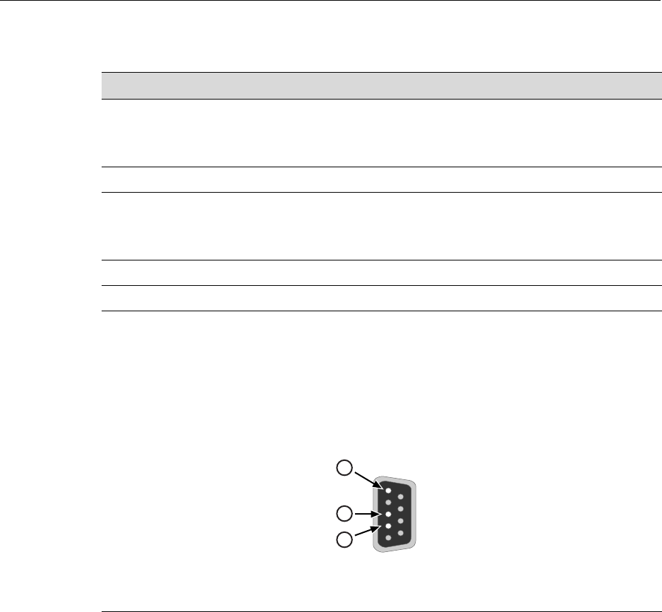
Console Port Pinout Assignments
SecureStack A2 PoE Installation Guide A-7
MGBIC-02 Specifications (1000BASE-T)
Console Port Pinout Assignments
TheConsoleportisaDB9serialcommunicationsportforlocalaccesstoLocal
Management.RefertoFigure A‐1fortheConsoleportpinassignments.
Figure A-1 Console Port Pinout Assignments
Table A-12 MGBIC-02 Specifications
Item Specification
Supported Cable:
Type
Maximum Length
Copper, Category 5 UTP
Up to 100 meters
Connector RJ45
Data Rate 1 Gbps, IEEE 802.3:2000 compatible
1000BASE-T operation only
Automatic crossover detection
TX Output impedance 100 ohms, typical at all frequencies between 1 MHz and 125 MHz
RX Input impedance 100 ohms, typical at all frequencies between 1 MHz and 125 MHz
1Pin 2, Received Data (input) 3Pin 5, Signal Ground
2Pin 3, Transmitted Data (output) All other pins not connected.
5
1
9
6
3
2
1

Regulatory Compliance
A-8 Specifications
Regulatory Compliance
TheA2H124‐24PandA2H124‐48Pmeetthesafetyandelectromagneticcompatibility
(EMC)requirementslistedinTable A‐13:
Table A-13 Compliance Standards
Regulatory Compliance Standards
Safety UL 60950, CSA C22.2 No. 60950, 73/23/EEC, EN 60950,
IEC 60950, EN 60825, 21 CFR 1040.10
Electromagnetic Compatibility (EMI)
(Class A)
47 CFR Parts 2 and 15, CSA C108.8, 89/336/EEC,
EN 55022, EN 61000-3-2, EN 61000-3-3, EN 55024,
AS/NZS CISPR 22, VCCI V-3

Index-1
Index
Numerics
1000BASE-SX/LX network connections
requirements for 2-2
1000BASE-T
requirements for 2-2
100BASE-TX
requirements 2-2
10BASE-T
connection 3-19
requirements 2-1
A
A2H124-24P
overview of 1-2
A2H124-48P
overview of 1-2
C
Cable
fiber budget A-4
Cable specifications
1000BASE-SX/LX network 2-2
1000BASE-T network 2-2
100BASE-TX network 2-2
10BASE-T network 2-1
CLI command
introduction to 1-6
Configuring switches
stack configuration 3-9
Connecting to the network 3-19
Connectivity
introduction to 1-5
Console port
pinout assignments A-7
D
Document conventions xvii
E
Electromagnetic Compatibility (EMC)
requirements A-8
Enterasys
contacting 1-7
F
Fiber budget A-4
Front panel 1-3
H
High-Speed Stack Connections
introduction to 1-4
High-speed stacking cables
installation of 3-7
I
Installation
connecting to the network 3-19
high-speed stacking cables 3-7
in a rack 3-6
new stack 3-10
new switch in existing stack 3-11
optional Mini-GBIC 3-22
Installation site
what is needed at the 3-5
L
LANVIEW Diagnostic LEDs
introduction to 1-7
LANVIEW LEDs 4-2
Link LEDs
viewing of 4-2
Local Management
introduction to 1-6
M
Management
use of 1-6
MGBIC-02 A-7
MGBIC-08
specifications for A-6
MGBIC-LC01
specifications for A-4, A-5
MGBIC-LC03
specifications for A-5
MGBIC-LC09
specifications for A-6
MGBIC-MT01
specifications for A-4, A-5
Mini-GBIC
installation of 3-22
removal of 3-26
Mini-GBIC input/outputs
specifications for A-4
P
PD (Powered Device)
definition of xv
Index-2
Pinout assignments
console port A-7
UTP 4-wire crossover cable 3-21
UTP 4-wire straight-through cable 3-21
UTP 8-wire crossover cable 3-21
UTP 8-wire straight-through cable 3-22
PoE (Power over Ethernet)
introduction to 1-4
Power connection
AC 3-12
RPS DC 3-13
R
Rackmount installation
guidelines for 3-6
Receive/Transmit LEDs
viewing of 4-2
Redundant Power Supply Capability
introduction to 1-4
Regulatory Compliance A-8
Related manuals xvi
S
Safety requirements A-8
Specifications A-1
A2H124-24 A-1
A2H124-48 A-3
MGBIC-08 A-6
MGBIC-LC01 A-4, A-5
MGBIC-LC03 A-5
MGBIC-LC09 A-6
MGBIC-MT01 A-4, A-5
Mini-GBIC input/outputs A-4
Stack initialization
manager switch selection 3-14
Stack Manager
automatic selection of 3-14
Stack Member
automatic selection of 3-14
Stack Operation
member switch selection 3-14
Stack System
installation of a new switch in existing stack 3-11
installation of new 3-10
Standalone Switches
specifications for A-1
Standards compatibility 1-6
Switch A-1
overview of 1-2
Switch carton
contents of 3-2
unpacking of 3-2
Switch Operation
stack installation 3-9
T
Table A-2 A-1
Troubleshooting 4-2
U
Unpacking the module 3-2
Using the Reset Password Switch 4-9
V
Viewing Receive and Transmit Activity
instructions for 4-2
W
WebView
introduction to 1-6
