Enviro Ea800 Users Manual Winland
EA800 to the manual f2128ec7-d2be-48f8-813d-ca3d4eee5491
2015-02-06
: Enviro Enviro-Ea800-Users-Manual-540564 enviro-ea800-users-manual-540564 enviro pdf
Open the PDF directly: View PDF ![]() .
.
Page Count: 98
- Table of Contents
- General Information
- Preparation
- Installation
- Tools and Supplies Required
- Power Requirements
- Mounting the EA800 Rear Plate
- Install the Wired Sensors
- EA800 Base Unit Power Connections
- Install the Wireless Sensors
- Connecting Wired Temperature, Contact Closure, and Water Bug Sensors
- Connecting Wired HA-III+ Humidity Sensors
- Connecting Wired 4-20mA Sensors
- Connecting the EA800 Alarm Outputs
- Programming
- Adding Wireless Sensors
- Adding a Wireless Temperature Sensor
- Adding a Wireless Multi-Function Sensor Using a Wired Temperature Sensor
- Adding a Wireless Humidity Sensor
- Adding a Wireless Multi-Function Sensor Using a Wired WaterBug Sensor
- Adding a Wireless Multi-Function Sensor Using a Wired Contact Closure Sensor
- Verify Wireless Signal Strength
- Adding Wired Sensors
- Configuring the Relays
- Operation
- Maintenance
- Locking and Unlocking the EA800
- Pausing Monitoring and Cancelling Pause
- Adding a Sensor
- Replacing a Sensor
- Editing Sensor Parameters
- Reprogramming a Relay
- Deleting a Sensor
- Changing the Date Format
- Changing the Time Format
- Changing the Date or Time Setting
- Changing Sensor Data Collection Frequency
- Changing the Buzzer Setting
- Changing the Password
- Clearing the Alarm Log
- Clearing the Sensor Log
- Updating the Firmware
- Saving Configuration Settings
- Loading Configuration Settings
- Exporting the Stored Logs
- Troubleshooting
- Specifications
- Appendix A: Screen Maps
- Appendix B: Planning Worksheet
- Appendix C: Wiring Diagram
- Appendix D: System Configuration Record
- Warranty and Service Information
D-011-0152
Electronic Multi-Zone Environmental Alarm System
Installation/Owner’s Manual
Limitations of the Alarm System or Device
While your alarm system or device is reliable and sophisticated, it does not offer guaranteed protection against
burglary, fire or other emergency. Any security product, whether commercial or residential, is subject to
compromise or failure-to-warn for a variety of reasons. These include:
•Individuals may gain access through unprotected openings or have the technical sophistication to
bypass an alarm sensor or disconnect an alarm warning device.
•Monitoring devices will not operate without power. Devices powered by AC will not work if their AC
power supply is off for any reason. If system has battery backup, batteries that are not maintained can
fail to provide the necessary power for devices to function properly.
•Alarm warning devices such as sirens, bells, and horns may not alert people or awaken sleepers if they
are located on the other side of closed or partly closed doors. If warning devices are on a different level
of the residence from the bedrooms, they are less likely to awaken or alert people inside the bedrooms.
•Telephone lines needed to transmit alarm signals from a premises to a central monitoring station may
be out of service, and are subject to compromise by sophisticated means of attack.
•Signals sent by wireless transmitters may be blocked or reflected by metal before they reach the alarm
receiver. Even if the signal path has been recently checked during a weekly test, blockage can occur if
a metal object is moved into the path.
•Even if the system responds to the emergency as intended and is a monitored alarm system, the
authorities may not respond appropriately.
•This equipment, like other electrical devices, is subject to component failure.
•The most common cause of an alarm system not functioning properly is due to inadequate
maintenance. Your alarm system should be tested weekly to make sure all detection devices are
operating properly. Your control panel and keypads should be tested as well.
Installing an alarm system may make you eligible for lower insurance rates, but an alarm system is not a substitute
for insurance. Homeowners, property owners, and renters should continue to insure their lives and property.

D
-
011
-
0152
i
Table of Contents
General Information............................................................................................................................... 1
Overview ............................................................................................................................................ 1
How to Use This Manual.................................................................................................................... 2
Block Diagrams.................................................................................................................................. 3
Symbols on the Product or Manual Labeling ..................................................................................... 4
Monitoring Screens............................................................................................................................ 5
Keys ................................................................................................................................................... 6
Base Unit Connections ...................................................................................................................... 7
Access Control and Passwords ......................................................................................................... 8
System Configuration Parameters ..................................................................................................... 9
Sensors............................................................................................................................................ 10
Temperature Sensors ................................................................................................................ 10
Humidity Sensors....................................................................................................................... 11
4-20mA Sensors ........................................................................................................................ 11
Theory of Operation ....................................................................................................... 11
Power Supply / Sensor Voltage Selection...................................................................... 12
Water Sensors ........................................................................................................................... 13
Multi-Function Sensors .............................................................................................................. 13
Contact Closure Sensors ........................................................................................................... 13
Sensor Parameter Descriptions ................................................................................................. 14
Relay Operation ............................................................................................................................... 15
Preparation........................................................................................................................................... 17
Installation............................................................................................................................................ 21
Tools and Supplies Required........................................................................................................... 21
Power Requirements ....................................................................................................................... 21
Mounting the EA800 Rear Plate ...................................................................................................... 21
Install the Wired Sensors................................................................................................................. 22
EA800 Base Unit Power Connections ............................................................................................. 22
Install the Wireless Sensors............................................................................................................. 22
Connecting Wired Temperature, Contact Closure, and Water Bug Sensors................................... 24
Connecting Wired HA-III+ Humidity Sensors................................................................................... 25
Connecting Wired 4-20mA Sensors................................................................................................. 26
Connecting the EA800 Alarm Outputs............................................................................................. 27
Programming ................................................................................................................................... 27
Accessing the MAIN MENU for Programming ........................................................................... 28
Configuring System Parameter Settings.................................................................................... 28
Setting the Current Date ............................................................................................................ 31
Setting the Time......................................................................................................................... 32
Adding Wireless Sensors................................................................................................................. 33
Adding a Wireless Temperature Sensor .................................................................................... 33
Adding a Wireless Multi-Function Sensor Using a Wired Temperature Sensor ........................ 35
Adding a Wireless Humidity Sensor........................................................................................... 37
Adding a Wireless Multi-Function Sensor Using a Wired WaterBug Sensor ............................. 38
Adding a Wireless Multi-Function Sensor Using a Wired Contact Closure Sensor ................... 40
Verify Wireless Signal Strength ................................................................................................. 42
Adding Wired Sensors ..................................................................................................................... 43
Adding a Wired Temperature Sensor ........................................................................................ 43
Adding a Wired HA-III+ Humidity Sensor................................................................................... 44
Adding a Wired WaterBug Sensor ............................................................................................. 45
Adding a Wired Contact Closure Sensor ................................................................................... 46
Adding a 4-20mA Sensor........................................................................................................... 47
Configuring the Relays..................................................................................................................... 48

ii D-011-0152
Operation .............................................................................................................................................. 49
Monitoring Environmental Conditions .............................................................................................. 49
Viewing Sensor Settings .................................................................................................................. 50
Viewing Active Alarms ..................................................................................................................... 50
Viewing the Alarm Log ..................................................................................................................... 51
Viewing Pending Alarm Information................................................................................................. 51
Viewing Limit Settings...................................................................................................................... 52
Viewing the Event Log ..................................................................................................................... 52
Viewing the Sensor Log ................................................................................................................... 53
Viewing Firmware Information ......................................................................................................... 53
Viewing RF Information.................................................................................................................... 54
Maintenance ......................................................................................................................................... 55
Locking and Unlocking the EA800 ................................................................................................... 55
Pausing Monitoring and Cancelling Pause ...................................................................................... 56
Adding a Sensor .............................................................................................................................. 57
Replacing a Sensor.......................................................................................................................... 57
Editing Sensor Parameters .............................................................................................................. 58
Reprogramming a Relay .................................................................................................................. 59
Deleting a Sensor ............................................................................................................................ 59
Changing the Date Format............................................................................................................... 60
Changing the Time Format .............................................................................................................. 60
Changing the Date or Time Setting.................................................................................................. 61
Changing Sensor Data Collection Frequency.................................................................................. 61
Changing the Buzzer Setting ........................................................................................................... 62
Changing the Password................................................................................................................... 63
Clearing the Alarm Log .................................................................................................................... 64
Clearing the Sensor Log .................................................................................................................. 64
Updating the Firmware..................................................................................................................... 65
Saving Configuration Settings.......................................................................................................... 66
Loading Configuration Settings........................................................................................................ 67
Exporting the Stored Logs ............................................................................................................... 68
Exported Alarm Data.................................................................................................................. 68
Exported Event Data.................................................................................................................. 69
Exported Sensor Data................................................................................................................ 69
Troubleshooting................................................................................................................................... 71
Verifying RF Signal Strength............................................................................................................ 72
Viewing Signal Strength for a Wireless Sensor.......................................................................... 72
Specifications....................................................................................................................................... 73
Base Unit and Sensor Specifications............................................................................................... 73
Accessories...................................................................................................................................... 74
Appendix A: Screen Maps................................................................................................................... 75
Appendix B: Planning Worksheet ...................................................................................................... 83
Appendix C: Wiring Diagram .............................................................................................................. 85
Appendix D: System Configuration Record ...................................................................................... 87
Warranty and Service Information ..................................................................................................... 93
D
-
011
-
0152
1
General Information
Overview
The EnviroAlert® EA800 Multi-Zone Environmental Alarm System monitors the environmental conditions detected
by the sensors connected to the base unit, and provides alarm signals when monitored conditions at any of the
sensors exceed the user-programmable HIGH LIMIT or LOW LIMIT set points. The alarm signals are provided via
relay outputs that can operate with process controls, security systems, or other similar automated equipment. The
EA800 Alarm System can be configured with wired or optional wireless sensors (sold separately). The EA800
allows connection of up to 4 wired and 4 wireless sensors.
Setup and programming is done using the front panel keys and the liquid crystal display (LCD) on the base unit.
The display assists the user during setup, and shows measured conditions for the monitored environment during
operation.
The EA800 can monitor multiple critical environments using multiple sensor inputs. Each sensor input/alarm
channel is designated a “Relay”.
Using the appropriate accessory sensors (sold separately), the EA800 Alarm System monitors and provides
alarms for the following conditions:
■Normally open/normally closed contacts
■Temperature: from -80° C to 150° C (-112° F to 302° F)
■Humidity: from 5% to 95% RH (non-condensing)
■Presence of water
■Any sensor with a 4-20mA interface
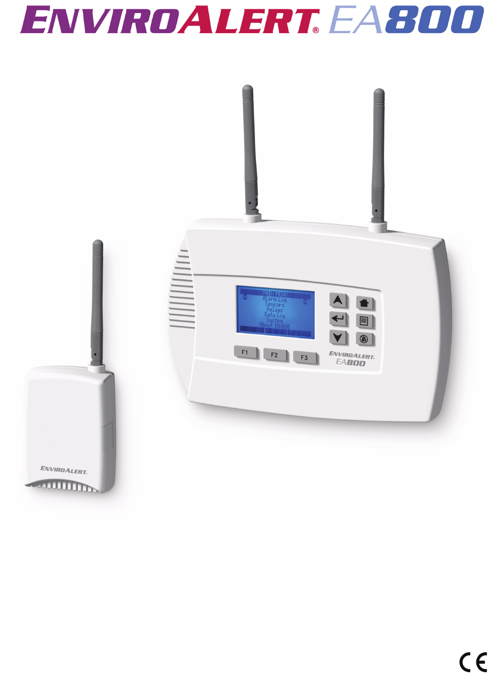
The EA800 base unit may be mounted directly to a 3-gang electrical enclosure or to walls. The wireless sensors
are easily mounted to the wall. Figure 1 shows the base unit and a wireless sensor.
Figure 1 EnviroAlert EA800 Base Unit and Optional Wireless Sensor
2D-011-0152
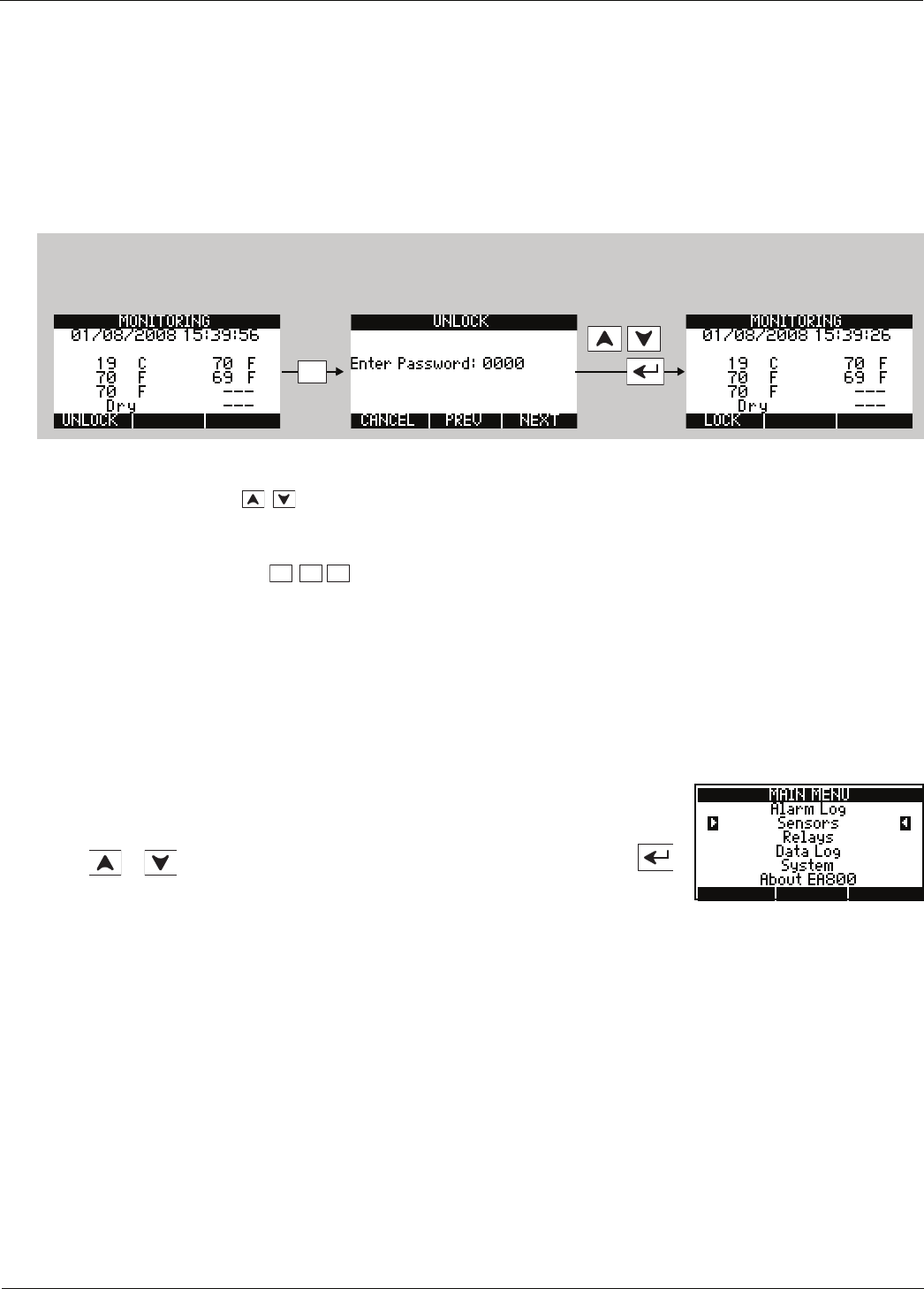
How to Use This Manual
How to Use This Manual
This manual is organized into sections that guide you through the installation process, then describe how to use the
EA800 and change its programmed settings if necessary. Some troubleshooting guidelines are provided, and the
appendices contain forms for you to photocopy and use to record the programmed settings of the EA800 and the
monitoring system setup.
The manual presents EA800 programming procedures by showing you the sequence of menus and screens you
will see as you perform the procedure, and the keys to press to advance to the next screen. The example below is
the procedure for unlocking the EA800 base unit to allow programming.
The arrows on the drawing indicate the direction of procedure flow.
In all procedures, use the keys to select menu options and to increase/decrease alphanumeric values for
programming options. Use the PREV and NEXT soft keys (F2 and F3) to move the cursor to the next digit when
entering numeric data.
The functions of the soft keys change and are defined on the screen in the area above each key. If no
text is shown above a soft key, it means the key performs no function on the current screen.
“Keys” on page 6 describes the functions of each key on the base unit.
Note: For convenient reference, “Appendix A: Screen Maps” on page 75 contains maps of all menus and
screens.
Throughout the manual, text that appears on the EA800 base unit screens is shown like this: MONITORING
Key names are shown in text like this: F1
The current menu selection is highlighted on the screen by arrows on either side of the
selection, as shown in the example at right. On this MAIN MENU screen, the current selection
is Sensors.
Use the or keys to move the highlight to the desired menu item, then press
to make the selection.
Enter:
0800
F1
Step 1: Press the
F1 soft key.
Step 2: The UNLOCK screen
is displayed. Enter your
password using the arrow
keys.
Step 3: Press the
ENTER key
F1 can be pressed at this time
to lock the unit.
F1 F2 F3
General Information
D
-
011
-
0152
3
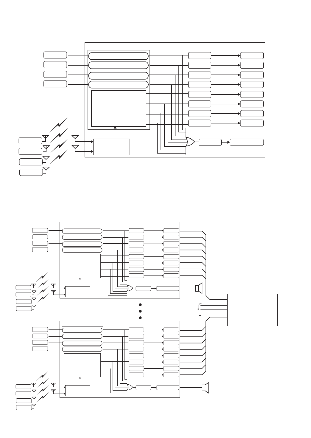
Block Diagrams
Figure 2 shows a block diagram of the base unit interfaces and functions. The EA800 provides eight relays for
indicating when a programmed alarm limit has been exceeded or a warning condition exists. An additional AUX
(Auxiliary) Output relay provides an output signal to an optional audible alarm or strobe that is activated whenever
an alarm condition exists.
Figure 2 EA800 Environmental Alarm System Block Diagram
The EA800 can be made part of a larger security system as shown in Figure 3. In a security system there may be
more than one EA800 installed along with other components such as the Winland EA200 or EA400 multi-zone
environmental alarm systems.
Figure 3 Facility Security System Block Diagram - Example
Sensor 5
Sensor 6
Sensor 7
Sensor 8
Wireless Sensors
Relay 1 Output 1
Output 2
Relay 2
Output 3
Relay 3
Output 4
Relay 4
Output 5
Relay 5
Output 6
Relay 6
Output 7
Relay 7
Output 8
Relay 8
EA800 Base Unit
Aux Output
RF Receiver
Sensor 1
Sensor 2
Sensor 3
Sensor 4
System Control
Relay 9
Relay 1 coil control logic
Relay 2 coil control logic
Relay 3 coil control logic
Relay 4 coil control logic
Relay assignment
and coil control logic
Alarm Panel
From other
EA800, EA400, and EA200
Environmental Alarm Systems
Sensor 5
Sensor 6
Sensor 7
Sensor 8
Wireless Sensors
Relay 1 Output 1
Output 2
Relay 2
Output 3
Relay 3
Output 4
Relay 4
Output 5
Relay 5
Output 6
Relay 6
Output 7
Relay 7
Output 8
Relay 8
EA800 Base Unit
Aux Output
RF Receiver
Sensor 1
Sensor 2
Sensor 3
Sensor 4
System Control
Relay 9
Relay 1 coil control logic
Relay 2 coil control logic
Relay 3 coil control logic
Relay 4 coil control logic
Relay assignment
and coil control logic

4D-011-0152
Symbols on the Product or Manual Labeling
Symbols on the Product or Manual Labeling
Symbols appearing on the product labeling, packaging, and/or in this manual are shown and described in Table 1.
Table 1 Symbols on Product or Manual
Symbol Definition
Attention, consult accompanying documents or statements.
For product disposal, ensure the following:
• Do not dispose of this product as unsorted municipal waste.
• Collect this product separately.
• Use collection and return systems available to you.
Indicates product complies with RoHS-WEEE directive.
NO Normally Open (NO) relay contact terminal
NC Normally Closed (NC) relay contact terminal
CCommon relay contact terminal
AUX Combined single pole double throw (SPDT) NO relay output that activates upon an
alarm from any of the sensors.
Model: EA800
• FCC ID:
V5SEA800-031108
• IC: 7635A-EA800
Models: EA-WMFS,
EA-WTS, EA-WHS
• FCC ID:
V5SEA-WS-031108
• IC: 7635A-EAWS
This device complies with part 15 of the FCC Rules. Operation is subject to the follow-
ing two conditions: (1) This device may not cause harmful interference, and (2) this
device must accept any interference received, including interference that may cause
undesired operation.
Caution Statement (per CFR 15.21):
Changes or modifications not expressly approved by the party responsible for compli-
ance could void the user’s authority to operate the equipment.
Class B Product Compliance Statement (per CFR 15.105(b)):
NOTE: This equipment has been tested and found to comply with the limits for a
Class B digital device, pursuant to part 15 of the FCC Rules. These limits are
designed to provide reasonable protection against harmful interference in a residential
installation. This equipment generates, uses and can radiate radio frequency energy
and, if not installed and used in accordance with the instruction, may cause harmful
interference to radio communications. However, there is no guarantee that interfer-
ence will not occur in a particular installation. If this equipment does cause harmful
interference to radio or television reception, which can be determined by turning the
equipment off and on, the user is encouraged to try to correct the interference by one
or more of the following measures:
• Reorient or relocate the receiving antenna.
• Increase the separation between the equipment and receiver
• Connect the equipment into an outlet on a circuit different from that to which the
receiver is connected.
• Consult the dealer or an experienced radio/TV technician for help.
The TÜV certification combines electrical safety certification for Canada (SCC), United
States (NRTL), and Europe (EU Directives). This product was voluntarily tested
according to the relevant safety requirements and mentioned properties pertaining to
this certification mark.
The product is in conformity with all applicable requirements for its placing on the
European Union market.
General Information
D
-
011
-
0152
5
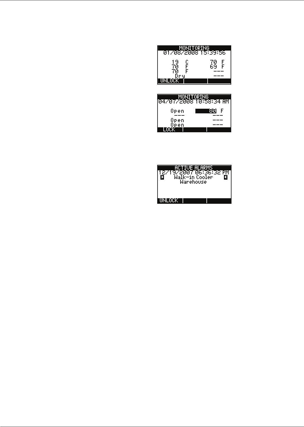
Monitoring Screens
The EA800 user interface is menu-based. During normal system monitoring, one of the following three screens is
displayed depending on the current state of the programmed sensors:
The MONITORING (home) screen is displayed
when there are no active alarms. The screen lists
all programmed sensors connected to the base
unit and their current reading or state.
The MONITORING (home) screen displays pending
alarms in reverse video as shown in the example
at right (71° exceeds the temperature limit for
Sensor 2, so it is shown as light text on black).
Pending alarms indicate that the programmed lim-
its for the sensor have been exceeded, but the
sensor’s programmed delay time has not elapsed
yet. If the monitored conditions continue to
exceed the programmed limits for longer than the
programmed delay period, the pending alarm will
become an active alarm.
The ACTIVE ALARMS screen is shown when one or
more sensors are in an active alarm or warning
state. If more than one alarm is active, each will
be listed on the screen. In the example shown,
Walk-in Cooler and Warehouse alarms are
occurring simultaneously.
6D-011-0152
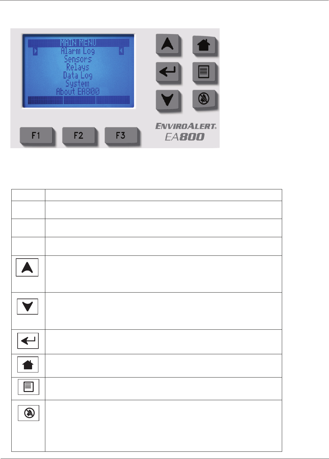
Keys
Keys
Figure 4 shows the base unit display and entry keys. The keys are described in Table 2.
Figure 4 EA800 Base Unit Keys
Table 2 Key Functions
Key Function
F1 This key's function changes as determined by the software. Its current function is
displayed immediately above the key on the display.
F2 This key's function changes as determined by the software. Its current function is
displayed immediately above the key on the display.
F3 This key's function changes as determined by the software. Its current function is
displayed immediately above the key on the display.
Up Arrow: This key provides the scroll up function. It moves the selection cursor up
a list or increments the value of alphanumeric entry fields as identified by the flash-
ing cursor. The values provided are dependent on the currently active field. For
example, the available selections may be a + or - sign, numbers, or alphanumeric
characters and special characters.
Down Arrow: This key provides the scroll down function. It moves the selection
cursor down a list or decrements the value of alphanumeric entry fields as identified
by the flashing cursor. The values provided are dependent on the currently active
field. For example, the available selections may be a + or - sign, numbers, or alpha-
numeric characters and special characters.
ENTER key. This key accepts the currently entered selection when pressed. If the
selection is a menu item, the selected item is accessed. If the current selection is an
entered value, pressing the ENTER key accepts the entered value.
HOME key. This key displays the home screen (MONITORING) when pressed.
MENU key: Displays the MAIN MENU screen when pressed from any menu level or
from the home screen.
SILENCE key: Alarms cannot be cleared and will continue to recur until the moni-
tored conditions detected by the sensors are within the programmed parameters.
Pressing the SILENCE key temporarily silences the local audible alarm and deacti-
vates the auxiliary relay for 10 minutes.
If a new alarm originating from a different sensor occurs within this 10-minute
period, the audible alarm and aux relay are reactivated, and require another key
press to silence the audible alarm.

General Information
D
-
011
-
0152
7
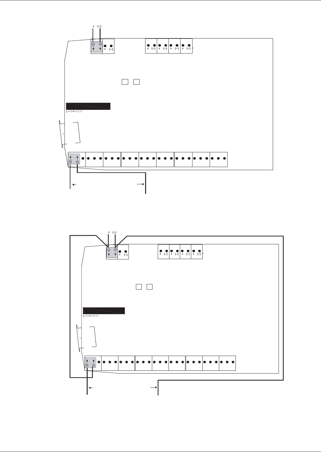
Base Unit Connections
Figure 5 shows the EA800 base unit's connections and Table 3 describes the functions of each connection.
Note: The base unit has four wired sensor inputs and four wireless RF sensor inputs.
Figure 5 EA800 Base Unit Connections
Table 3 EA800 Base Unit Connector Functions
Connector Designation Function
J2 USB USB Type A connection used to program firmware, export logs, and export
and import configuration files. www.winland.com lists compatible USB sticks.
J5 Power In 11-26 VDC input power connection for EA800 base unit (from accessory
power supply or alarm panel).
CAUTION
!
CAUTION
Observe (+) and (-) polarity markings screened on circuit board. EA800
can be damaged if power polarity is reversed.
Aux Power Out 11-26 VDC power out connection for EA800 accessories requiring power
(such as HA-III+ Humid Alert). This output voltage equals that of Power In and
is current-limited to a maximum of 500 mA.
CAUTION
!
CAUTION
Connect only accessories specified in this manual to the Aux Power Out
connection. Connection of unsuitable loads to this connection may
damage the power supply and EA800, or result in improper or unreliable
operation.
Note: Accuracy for the HA-III+ sensor is stated at +12VDC input.
If Aux Power Out is used to power the HA-III+ and is not
+12VDC, then the accuracy of the HA-III+ is compromised.
Power
In
Aux
Power
Out
J6
J5
Input 1 Input 2 Input 3 Input 4
J13 J14
J2
J10J8 J9
Output 1 Output 2 Output 3 Output 4 Output 5 Output 6 Output 7 Output 8 Aux
NO COM NC NO COM NC NO COM NC NO COM NC NO COM NC NO COM NC NO COM NC NO COM NC NO COM NC
8D-011-0152
Access Control and Passwords
Access Control and Passwords
The EA800 base unit is normally locked to prevent unauthorized use. The currently active function of the F1 soft
key (UNLOCK or LOCK) is displayed above the key. The locked and unlocked states are described below.
Note: The base unit locks automatically after 30 minutes of inactivity if the user does not press the LOCK soft
key (F1).
■Locked: This is the default state and limits access to the EA800 to viewing only.
UNLOCK is displayed above the F1 soft key indicates that the base unit is
currently locked. Pressing the F1 soft key prompts the user to enter a password
to unlock the base unit, permitting full access to all screens and functions. The
HOME key, MENU key, and the MAIN MENU options shown on the screen at right
are available to the user when the base unit is locked.
■Unlocked: When the base unit is unlocked, LOCK displayed above the F1 soft key, and all information,
programming, and maintenance screens may be viewed and programming changes may be made. Pressing
the F1 soft key locks the EA800 base unit and protects it from unauthorized or unintended programming
changes, log downloads, and firmware uploads.
The base unit allows the use of two passwords for unlocking:
■The factory default password is 0800. This password cannot be changed or deleted.
■A second, optional password may be set by the user. To create a second user password, see “Changing the
Password” on page 63.
J6 INPUT 1 Wired input for Relay 1 external temperature, water, 4-20mA, contact closure,
or humidity sensor.
INPUT 2 Wired input for Relay 2 external temperature, water, 4-20mA, contact closure,
or humidity sensor.
INPUT 3 Wired input for Relay 3 external temperature, water, 4-20mA, contact closure,
or humidity sensor.
INPUT 4 Wired input for Relay 4 external temperature, water, 4-20mA, contact closure,
or humidity sensor.
J8 OUTPUT 1 Form C relay alarm output for Relay 1.
OUTPUT 2 Form C relay alarm output for Relay 2.
OUTPUT 3 Form C relay alarm output for Relay 3.
J9 OUTPUT 4 Form C relay alarm output for Relay 4.
OUTPUT 5 Form C relay alarm output for Relay 5.
OUTPUT 6 Form C relay alarm output for Relay 6.
J10 OUTPUT 7 Form C relay alarm output for Relay 7.
OUTPUT 8 Form C relay alarm output for Relay 8.
AUX OUT Form C relay output that activates upon an alarm from any of the relays
(Relay 1 through Relay 8).
J13 Antenna RF receive and transmit
J14 Antenna RF receive and transmit
Table 3 EA800 Base Unit Connector Functions — continued
Connector Designation Function

General Information
D
-
011
-
0152
9
System Configuration Parameters
The EA800 base unit requires certain system level information as outlined in Table 4.
Table 4 System Configuration Parameters
Parameter Selections Factory Default Description
Date Format • MM/DD/YYYY
• DD/MM/YYYY MM/DD/YYYY Sets the desired date format for all event time stamps.
Time Format • 12-hour
• 24-hour 24-hour Sets the desired time format for all event time stamps.
Data Collec-
tion Fre-
quency
• 30 seconds
• 1 minute
• 5 minutes
• 15 minutes
• 30 minutes
• 60 minutes
5 minutes Sets the interval for collecting and recording data from the
sensors. The data collection frequency applies to all sen-
sors.The EA800 provides approximately 10,000 data
points to be collected regardless of the frequency
selected. The estimated time duration covered for each
data collection frequency is listed below.
30 seconds = 3.5 days
1 minute = 1 week
5 minutes = 1 month
15 minutes = 3 months
30 minutes = 6 months
60 minutes = 1 year
Buzzer • Enable
•Disable Enabled Enables and disables the buzzer when an alarm limit has
been exceeded or a warning condition exists.
WARNING
!
Selecting Disable for this parameter turns the audible
alarm buzzer off completely. No audible alarm tone
will sound when an alarm occurs if DISABLE is
selected.
RF Channel 11 (2405 MHz)
12 (2410 MHz)
13 (2415 MHz)
14 (2420 MHz)
15 (2425 MHz)
16 (2430 MHz)
17 (2435 MHz)
18 (2440 MHz)
19 (2445 MHz)
20 (2450 MHz)
21 (2455 MHz)
22 (2460 MHz)
23 (2465 MHz)
24 (2470 MHz)
25 (2475 MHz)
26 (2480 MHz)
channel 16 Selects the ISM band radio frequency (RF) channel for
transmission between the wireless sensors and EA800
base unit.

10 D-011-0152
Sensors
Sensors
A variety of sensors may be used with the EA800 base unit to provide environmental status and information. These
include the following:
■Wired Sensors: Relays 1 through 4 are for use with sensors wired to the base unit. Wired sensors can be any
of the following types:
•Low temperature sensors - Blue Thermistor Probes
•High temperature sensors - Red Thermistor Probes
•Ultra Low temperature sensors - White Thermistor Probes
•HA-III+ humidity sensor
•Water Bug sensor (supervised)
•N.O. Contact
•N.C. Contact
•4-20 mA
■Wireless Sensors: Relays 5 through 8 are for use with wireless sensors. These sensors transmit to the EA800
base unit through RF links. Each wireless sensor is hard-coded with an address the base unit uses to identify
the sensors installed in the system. When you program the system you assign each installed wireless sensor
to a relay using its hard coded address. Wireless sensors can be any of the following types:
•Wireless Humidity Sensor (EA-WHS)
•Wireless Temperature Sensor (EA-WTS)
•Wireless Multi-Function Sensor (EA-WMFS): Any of the following wired sensors can be connected to the
wireless multi-function sensor, effectively converting the wired sensor to wireless:
•Low temperature sensors - Blue Thermistor Probes
•High temperature sensors - Red Thermistor Probes
•Ultra Low temperature sensors - White Thermistor Probes
•Water Bug sensor (supervised)
•Normally Open (NO) Contact
•Normally Closed (NC) Contact
Temperature Sensors
Table 5 lists the temperature sensors available for use with the EA800 Alarm System.
Table 5 EA800 Compatible Temperature Sensors
Sensor Part Number Description Operating Range/Parameters
High Temp Red,
Stainless Steel PN M-001-0081 Thermistor, Stainless Steel Probe,
High Temperature Sensor 0° C to 150° C
(32° F to 302° F)
Low Temp Blue,
Stainless Steel PN M-001-0082 Thermistor, Stainless Steel Probe,
Low Temperature Sensor -50° C to 70° C
(-58° F to 158° F)
Low Temp Blue,
waterproof PN M-001-0086 Thermistor, waterproof, low tempera-
ture sensor. For use in coolers and
freezers.
-50° C to 70° C
(-58° F to 158° F)
High Temp Red,
waterproof PN M-001-0087 Thermistor, waterproof, high tempera-
ture sensor 0° C to 150° C
(32° F to 302° F)
Ultra Low Temp
White, Stainless
Steel
PN M-001-0111 Thermistor Stainless Steel Probe,
Ultra Low Temperature Sensor -80° C to 0° C
(-112° F to 32° F)
Wireless Temp PN M-001-0125 Stand alone wireless temperature
sensor 0° C to 50° C
(32° F to 122° F)
General Information
D
-
011
-
0152
11
Humidity Sensors
Table 6 lists the humidity sensors available for use with the EA800 Alarm System.
4-20mA Sensors
Theory of Operation
Industry standard 4-20mA sensors can be used with the EA800. However, it is important to verify that this type of
sensor will operate properly over the entire output range.
Figure 6 shows an example of the loop circuit for a 4-20mA sensor whose minimum operating voltage is 8V or less
when connected to an EA800 base unit that is powered with 12VDC.
Figure 6 I4-20mA Sensor Wiring Diagram - EA800 Aux Power Supply
Figure 7 shows an example of the loop circuit for a 4-20mA sensor whose minimum operating voltage is greater
than 8V when connected to an EA800 base unit that is powered with 12VDC.
Figure 7 4-20mA Sensor Wiring Diagram - External Power Supply
Table 6 EA800 Compatible Humidity Sensors
Sensor Part Number Description Operating Range/Parameters
HA-III+ PN M-001-0091 Humidity monitoring module 5% to 95% rh
(non-condensing)
Wireless
Humidity PN M-001-0126 Wireless humidity monitoring
module 5% to 95% rh
(non-condensing)
+
DC
+
-
4.0V200O
Aux Power
J5
+
(-)
+
(-)
Input N
J6
+
-
Vsensor
4-20mA
Transmitter
EA800
Max Load of
200O includes
1000' of 22 AWG
(2 conductor)
wire connecting
the EA800 to the
4-20mA sensor
If Vsensor = 8V and Aux Power = 12V
+
DC
External
Supply
+
-
4.0V200O
Aux Power
J5
+
(-)
+
(-)
Input N
J6
+
-
Vsensor
4-20mA
Transmitter
EA800
Max Load of
200O includes
1000' of 22 AWG
(2 conductor)
wire connecting
the EA800 to the
4-20mA sensor
If Vsensor > 8V and Aux Power = 12V

12 D-011-0152
Sensors
Power Supply / Sensor Voltage Selection
In order to determine the power supply voltage necessary to ensure correct full-scale operation, it is necessary to
identify all voltage drops within the current loop.
Figures 6 and 7 show an EA800 drop of 4.0 VDC. This value accounts for the voltage drop generated by
connecting the 4-20mA sensor to the EA800 using 1000 feet of 22 AWG wire.
Now it is only necessary to identify the operating voltage range of the 4-20mA sensor, more importantly the
minimum operating voltage. Once identified, the minimum operating voltage of the sensor can be added to the
4.0V voltage drop of the EA800 (+ wire) to determine the power supply voltage necessary to ensure correct
full-scale operation.
Example:
■Assume that a 4-20mA sensor whose operating input voltage range is 10 – 30V has been selected for use.
Therefore the minimum operating voltage of the sensor is 10V (Vsensor). When the 4.0V drop of the EA800
(and wire) is added, it can be determined that at least 14VDC is needed to power the loop.
■If the EA800 is connected to a 12VDC power supply, use of the sensor in this example requires an external
power supply of at least 14V as shown in Figure 7.
It is important to not exceed the maximum operating voltage of the 4-20mA sensor, as specified within the sensor’s
product specification.
The following formula provides the basis for the selection matrix shown in Table 7. Please use Table 7 to select
either the proper sensor rating to be used with a known power supply, or select a power supply for a known sensor
rating.
RL < (Vcc – x) .023
where:
■RL = Loop resistance of 200
■Vcc = Power supplied to EA800 or Aux Power Out
■X = Sensor voltage (max)
Table 7 4-20mA Voltage Select Matrix
Power Supplied to EA800
or AUX. Power Out
Vsensor (max.) [Maximum
sensor voltage rating]
Power Supplied to EA800 or
AUX. Power Out
Vsensor (max.) [Maximum
sensor voltage rating]
11 VDC 7 VDC 19 VDC 15 VDC
12 VDC 8 VDC 20 VDC 16 VDC
13 VDC 9 VDC 21 VDC 17 VDC
14 VDC 10 VDC 22 VDC 18 VDC
15 VDC 11 VDC 23 VDC 19 VDC
16 VDC 12 VDC 24 VDC 20 VDC
17 VDC 13 VDC 25 VDC 21 VDC
18 VDC 14 VDC 26 VDC 22 VDC

General Information
D
-
011
-
0152
13
Water Sensors
Table 8 lists the water sensors available for use with the EA800 Alarm System.
Use of water sensors requires that at least one supervised water sensor be used. Up to five additional
unsupervised water sensors may be added in parallel on the same input where the supervised water sensor is
configured.
Multi-Function Sensors
Multi-function wireless sensors may be connected to a wired sensor to act as a transmitter. Table 9 lists the
multi-function sensor available for use with the EA800 Alarm System.
Contact Closure Sensors
Table 10 lists the contact closure sensors compatible for use with the EA800 Alarm System.
Table 8 EA800 Compatible Water Sensors
Sensor Part Number Description
Operating
Range/Parameters
Water Bug PN M-001-0094 Supervised water sensor1
1 Water sensors are not effective nor intended for use in distilled or deionized water.
NA
Table 9 EA800 Compatible Multi-Function Sensors
Sensor Part Number Description
Operating
Range/Parameters
Wireless
Multi-Function PN M-001-0127 Wireless link for sensors. See
page 16 for allowed sensors. Dependent on sensor
connected.
Table 10 EA800 Compatible Closure Sensors
Sensor Description
NO closure Normally open contact closure such as door contacts, motion detectors,
and glass break sensors
NC closure Normally closed contact closure such as door contacts, motion detectors,
and glass break sensors

14 D-011-0152
Sensors
Sensor Parameter Descriptions
This section provides a description of each sensor parameter.
Table 11 Sensor Parameter Descriptions
Parameter Applicable to Sensors Description
Sensor Name All A name used to identify the sensor in the alarm system. Select a name
readily identified by the viewer. The sensor name is displayed on the
Main screen during a no-alarm condition and on the Alarm screen during
an alarm condition. Two name choice types are available:
• Common Name: These are preprogrammed names.
• Custom Name: This selection allows you to enter any name if the
preprogrammed common names do not adequately identify the sensor
in the system (limited to 16 characters).
Note: Duplicate sensor names are not permitted.
Unit of
Measure • Blue, Red and White
temperature sensors
• 4-20mA sensor
• Wireless
temperature sensors
This parameter allows you to choose the unit of measure used for sen-
sor reading and display.
• Blue, Red and White temperature sensors: °C or °F
• 4-20mA sensors: the following Common Units of measure are
available: F (Fahrenheit), C (Centigrade), K (Kelvin), % rh (percent
relative humidity), psi (pounds per square inch), Pa (Pascals), kPa
(kiloPascals), lb (pound), kg (kilogram)
• 4-20mA sensors can also use custom units. Enter the appropriate units
for the connected 4-20mA sensor via the keypad.
Resolution 4-20mA sensor This determines the range that may be used for the 4-20mA sensor. The
full scale range is determined by the values entered in the Low Scaled
Value and the High Scaled Value. You must select the correct resolution
in order to set the true range limits for the 4-20mA sensor you are install-
ing. The available values are as follows:
Maximum Allowed Maximum Allowed
Resolution Low Scaled Value High Scaled Value
1. -9999. +9999.
0.1 -999.9 +999.9
0.01 -99.99 +99.99
0.001 -9.999 +9.999
Low Scaled
Value 4-20mA sensor This parameter equals the environmental reading that results in a sensor
output of 4mA or its minimum valid reading. This is dependent on the
setting of the resolution as discussed above.
High Scaled
Value 4-20mA sensor This parameter equals the environmental reading that results in a sensor
output of 20mA or its maximum valid reading. This is dependent on the
setting of the resolution as discussed above.
Hysteresis • Blue, Red and White
temperature sensors
• HA-III+
• 4-20mA sensor
The Hysteresis setting helps prevent alarms from being set and reset
continually if the environment is at or near the alarm set point by provid-
ing an acceptable variance. For example, if Hysteresis is set at 2 and the
sensor High limit is set at 50, the sensor reading must decrease to 48
(50 minus 2) in order for the alarm condition to reset to a no-alarm condi-
tion.
Low Alarm
Limit • Blue, Red and White
temperature sensors
• HA-III+
• 4-20mA sensor
• Wireless humidity
sensor
• Wireless
temperature sensor
The Low Alarm Limit sets the value that trips the low alarm when
exceeded.
General Information
D
-
011
-
0152
15
Relay Operation
This section describes the operation of the base unit's relays. The relays must be programmed correctly so that
their outputs provide the desired signaling to the alarm panel.
High Alarm
Limit • Blue, Red and White
temperature sensors
• HA-III+
• 4-20mA sensor
• Wireless humidity
sensor
•Wireless
temperature sensor
The High Alarm Limit sets the value that trips the high alarm when
exceeded.
Alarm Delay
Time All This sets the time period that an alarm condition can exist before the
alarm is triggered. This is useful for helping to prevent false alarms from
occurring in situations where normal activities cause conditions to tem-
porarily exceed alarm thresholds. For example, the temperature in a
freezer may temporarily rise above the High alarm limit while frozen food
is being restocked and the freezer door is open, but the delay prevents
the alarm from going off unless the temperature fails to cool below the
alarm threshold within the alarm delay period.
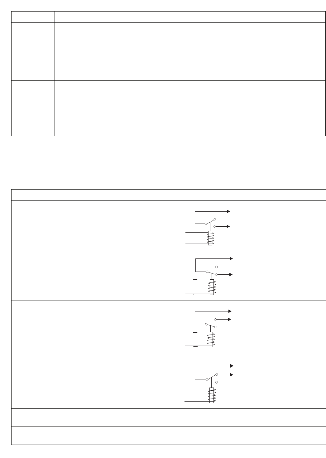
Table 12 Relay Configuration Settings
Relay Setting Description
No Alarm
Relay State:
De-Energized (default)
No Alarm: Power is removed from the relay coil as shown below.
Alarm: Power is applied to the relay coil as shown below.
No Alarm
Relay State: Energized No Alarm: Power is applied to the relay coil as shown below.
Alarm: Power is removed from the relay coil as shown below. This provides for a
default alarm if the EA800 loses power in addition to the sensors' alarms.
Active Condition:
Alarm Only Sets the alarm to be active when an alarm condition exists.
Active Condition:
Alarm or Warning (default) Sets the alarm to be active when an alarm condition exists or a warning is active.
Table 11 Sensor Parameter Descriptions — continued
Parameter Applicable to Sensors Description
NC
NO
To
alarm
panel
From
EA800
logic
Idc = 0
C
NC
NO
To
alarm
panel
From
EA800
logic
Idc
C
NC
NO
To
alarm
panel
From
EA800
logic
Idc
C
NC
NO
To
alarm
panel
From
EA800
logic
Idc = 0
C

16 D-011-0152
Relay Operation

D
-
011
-
0152
17
Preparation
Before you begin installation, ensure that you properly plan the alarm system. During the planning phase you will
generate all the documentation you need to successfully install the EA800 base unit and sensors in the alarm
system. This is important because complete and accurate installation documentation aids in system maintenance
later.
The suggested preparation procedure is as follows:
1. Read and understand the entire manual. General Information provides important information required to
properly plan, install, and use the EA800. The preparation phase helps ensure that the EA800 system will
function as required.
2. Photocopy the pages of Appendix B: Planning Worksheet, Appendix C: EA800 Wiring Diagram (one for each
EA800 base unit in the system), and Appendix D: System Configuration Record to create a record of the
specific EA800 alarm system installation you are currently working on.
3. Draw a floor plan for the facility where you will install the EA800 alarm system. Identify important details such
as the coolers, doors, computer rooms, etc. An example is shown below.
Figure 8 Example Floor Plan
4. Locate the base unit where authorized personnel can readily access it. If required, consideration should be
made regarding a location that discourages unauthorized access. If using wireless sensors, locate the base
unit to minimize the wireless distance. Ensure that the desired mounting locations for the EA800 base unit and
each sensor comply with the environmental specifications listed in Table 13: Specifications.
CAUTION
!
If the EA800 base unit will be connected to a remote alarm panel, do not connect
the base unit to the alarm panel until after sensor connection and configuration
is complete. Connecting the remote alarm panel before configuring the EA800
sensors will result in false alarms at the remote panel.
CAUTION
!
Do not install the EA800 base unit in coolers or freezers.
CAUTION
!
Use only wired sensors specified in this manual for the INPUT 1 through INPUT 4
connections. Unverified sensors may damage the EA800 or result in improper or
unreliable operation.
Cooler1 Cooler 2 Storage Room 3 Computer
Room
Rear
Entry
Front
Entry
Front Desk
Freezer 1 Freezer 2 Room 1 Room 2
Men's Room
Women's Room
Conference Room
Alarm panel
installation area

18 D-011-0152
5. Complete the copy of Appendix B: Planning Worksheet for the facility in which the EA800 system is to be
installed. This must include all monitored areas for the total security system so that you know how many EA800
base units are needed.
6. Determine the sensors required from the Planning Worksheet you completed and the information provided for
each sensor type in “System Configuration”. Enter these in the copy of the System Configuration Record you
made.
Note: When water sensors are required, you must use at least one supervised water sensor and may add up to
five additional unsupervised water sensors, all in parallel. Thus, an alarm on any sensor will result in an
alarm with no way to determine which sensor is the source.
7. Enter the sensor information in the copy of the EA800 Wiring Diagram you made. It is a good idea to name
each sensor on this diagram and use that name in both the EA800 Wiring Diagram and the System
Configuration Record. This helps ensure proper programming of the system after you have physically installed
the system.
8. Using the floor plan you created, identify the specific locations for each sensor and verify that their locations
meet the specifications. See Specifications for operational parameters such as cable length.
Note: For 4-20mA sensors: See 4-20mA Sensors for a discussion of determining the constraints for your
4-20mA sensor to ensure accuracy over its rated range.
9. Determine the channel to use for the wireless sensors. If more than one EA800 is being installed on-site, it is
recommended that they be configured to use different channels.
10. The wireless sensor must be located so that the wireless signal strength is adequate as outlined in Winland
Application Note AN00101. You must verify that the wireless sensors can communicate with the base unit
before you permanently mount them.
Note: Certain environments may present conditions that intermittently cause interference with wireless sensor
to base unit communications. You should understand the environment in which the EA800 is to operate
to minimize their affects on system performance.
11. Decide the loop design you will use. Figure 9 shows an alarm loop where alarm power is derived from the
alarm loop. Figure 10 shows an alarm loop where alarm power is derived from the power supply feeding the
EA800.
Note: if using a self-powered loop, ensure the power supply can provide power for all loading conditions.
WARNING
!
EA800 relay outputs are intended only for use as low-voltage, low-current
alarm connections, and not for direct switching or control of AC-mains
powered loads. Additionally, local codes may further dictate or limit the types
of loads and associated wiring to be used with the low-current Form C relay
outputs used with the EA800. Connecting AC-mains type circuits to the EA800
may result in an electric shock and/or fire hazard.
CAUTION
!
Do not connect a load to the AUX OUT or OUTPUT 1 through OUTPUT 8 relay
outputs that exceeds limitations stated in the Specifications section of this
manual. Loads exceeding the specified limitations may damage the EA800, or
result in improper or unreliable operation.
Preparation
D
-
011
-
0152
19
Figure 9 Typical Alarm Loop Wiring Configuration (External Power)
Figure 10 Typical Alarm Loop Wiring Configuration (Self-Powered)
Power
In
Aux
Power
Out
J6
J5 Input 1 Input 2 Input 3 Input 4
J13 J14
J2
J8 Output 1 Output 2 Output 3 Output 4 Output 5 Output 6 Output 7 Output 8 Aux
NO COM NC NO COM NC NO COM NC NO COM NC NO COM NC NO COM NC NO COM NC NO COM NC NO COM NC
From 11-26 VDC
power supply
To "alarm-on-closed"
loop circuit (power
supplied via loop)
Power
In
Aux
Power
Out
J6
J5 Input 1 Input 2 Input 3 Input 4
J13 J14
J2
J8 Output 1 Output 2 Output 3 Output 4 Output 5 Output 6 Output 7 Output 8 Aux
NO COM NC NO COM NC NO COM NC NO COM NC NO COM NC NO COM NC NO COM NC NO COM NC NO COM NC
From 11-26VDC
power supply
To "alarm-on-closed"
loop circuit (power
supplied via EA800)
To alarm + To alarm -
20 D-011-0152
12. Create an interconnect wiring diagram for the system. Identify the location of each sensor An example of a
system map is shown in Figure 11. This example illustrates a system that includes multiple EA800 Multi-Zone
Environmental Alarm systems, a Winland EA400 Multi-Zone Environmental Alarm system, and a Winland
EA200 Multi-Zone Environmental Alarm system.
Figure 11 System Interconnect Wiring Diagram Example
13. Determine the cabling required to complete the installation as indicated by the loop design, the sensors you
have selected, and the system interconnect wiring diagram.
14. Complete the System Configuration section on the copy of the System Configuration Record you made. See
System Configuration for a description of each system level parameter.
When you have completed the previous steps you are ready to proceed to physically install the EA800 base unit
and its associated sensors using the documentation you have just created.
Sensor 5
Sensor 7 Sensor 8
Relay 1
Output 1
Output 2
Relay 2
Output 3
Relay 3
Output 4
Relay 4
Output 5
Relay 5
Output 6
Relay 6
Output 7
Relay 7
Output 8
Relay 8
EA800 No. 1
Aux Output
Alarm Panel
Sensor 5
Sensor 6 Sensor 7 Sensor 8
Relay 1
Output 1
Output 2
Relay 2
Output 3
Relay 3
Output 4
Relay 4
Output 5
Relay 5
Output 6
Relay 6
Output 7
Relay 7
Output 8
Relay 8
EA800 No. 2
Aux Output
Computer
Room
Rear
Entry
Front
Entry
Front Desk
Men's Room
Women's Room
Conference Room
Alarm panel
installation area
Ch1
Ch2
Sensor 6
Ch1
Ch1
Ch1 Ch1
Ch2 Ch2 Ch2 Ch2
Zone 1
Output 1
Output 2
Zone 2
Output 3
Zone 3
Output 4
Zone 4
EA400
Aux Output
Internal
Sensor
Output 1
Output 2
Zone 1
EA200
Aux Output
Cooler1 Cooler 2
Storage Room 3
Freezer 1 Freezer 2 Room 1 Room 2

D
-
011
-
0152
21
Installation
Tools and Supplies Required
Ensure that you have the following prior to starting the installation:
■Phillips Screwdriver
■Mounting hardware for the EA800 base unit and any optional sensor units
■If required, a drill and the appropriate drill bits
■Wire stripper
■Sensors (not supplied; see “Accessories” on page 54)
■Sensor Wiring (typically 18-22 AWG twisted-pair; not supplied)
■Alarm Wiring (typically 18-22 AWG; see EA800 Output (Alarm) Connections)
■Power sources
Power Requirements
All power terminals must be connected to a Class 2 power limited circuit complying with the National Electric Code
NFPA 70, Article 725. Where required, this equipment is to be isolated from the mains supply by a limited power
source as specified in EN60950.
Mounting the EA800 Rear Plate
The base unit has a removable rear plate that may be attached to a 3-gang electrical enclosure or directly to a wall.
1. Remove the rear mounting plate from the base unit as follows:
■Pull the rear mounting plate down and away from the EA800 main chassis. The retainer tabs on the main
chassis disengage from the holes in the rear mounting plate.
■Completely remove the mounting plate from the base unit by disengaging the mounting plate hinges from the
mating tabs on the base unit.
WARNING
!
EA800 relay outputs are intended only for use as low-voltage, low-current alarm
connections, and not for direct switching or control of AC-mains powered loads.
Additionally, local codes may further dictate or limit the types of loads and
associated wiring to be used with the low-current Form C relay outputs used with
the EA800. Connecting AC-mains type circuits to the EA800 may result in an
electric shock and/or fire hazard.
CAUTION
!
Connect only sensors specified in this manual to the wired and wireless input
connections. Using sensors not specified in this manual may damage the EA800 or
cause improper or unreliable operation.
CAUTION
!
Do not connect a load to the AUX OUT or OUTPUT 1 through OUTPUT 8 relay
outputs that exceeds limitations stated in the Specifications section of this manual.
Loads exceeding the specified limitations may damage the EA800, or result in
improper or unreliable operation.
CAUTION
!
The EA800 printed circuit board (PCB) contains electrostatic discharge (ESD)
sensitive devices. To help prevent damage caused by ESD, observe appropriate
ESD handling rules whenever the PCB in the EA800 is exposed.
CAUTION
!
Batteries shall not cause explosion or produce a fire HAZARD as a result of
excessive charge or discharge, or if a battery is installed with incorrect polarity.
CAUTION
!
If the equipment is used in a manner not specified by the manufacturer, the
protection provided by the equipment may be impaired.

22 D-011-0152
Install the Wired Sensors
2. Mount the mounting plate as follows:
■Mounting to 3-gang enclosure: Use four (4) machine screws to secure the mounting plate to the mating holes in
the 3-gang enclosure.
■Mounting to drywall surface: Place the mounting plate in mounting position. Mark the four mounting hole
locations. Install drywall anchors and secure the mounting plate to the anchors.
Note: If wall-mounted, prepare a wiring access hole at this time. All wiring must pass through the opening in the
center of mounting plate.
Install the Wired Sensors
Install the wired sensors in accordance with the instructions provided with the wired sensors.
1. Mount each wired sensor in its designated location.
2. Label each sensor's wires for easy identification.
3. Route the wires from the sensor to the base unit and dress the wires as required by local code. It is important
to ensure that the wires are protected along their entire length, are not stressed at any point, and are
adequately supported along their entire length.
4. Pass the wires through the mounted EA800 rear panel.
EA800 Base Unit Power Connections
Note: Do not apply power to the base unit until you are ready to begin sensor programming. The base unit has
a 30-minute timer that starts when the unit is first powered up. If at least one sensor is not added and pro-
grammed within the 30-minute time period, an alarm will occur.
1. Using a terminal block adapter, connect power supply + and - leads to POWER IN (+) and (-) on J5. Observe
proper polarity. If using a transformer, ensure that the transformer is an isolated power supply.
2. If Aux Power Out is to be used, connect + and - leads to AUX POWER OUT (+) and (-) on J5 using a terminal
block adapter.
Install the Wireless Sensors
CAUTION
!
Do not connect or disconnect power, sensor, or alarm wiring while power is applied.
Connecting and disconnecting the EA800 base unit with power connected may damage the
base unit or result in improper or unreliable operation.
CAUTION
!
Connection of unsuitable loads to this connection may damage the power supply and
EA800 base unit, or result in improper or unreliable operation.
CAUTION
!
If the EA800 base unit will be connected to a remote alarm panel, do not connect
the base unit to the alarm panel until after sensor connection and configuration
is complete. Connecting the remote alarm panel before configuring the EA800
sensors will result in false alarms at the remote panel.
Installation
D
-
011
-
0152
23
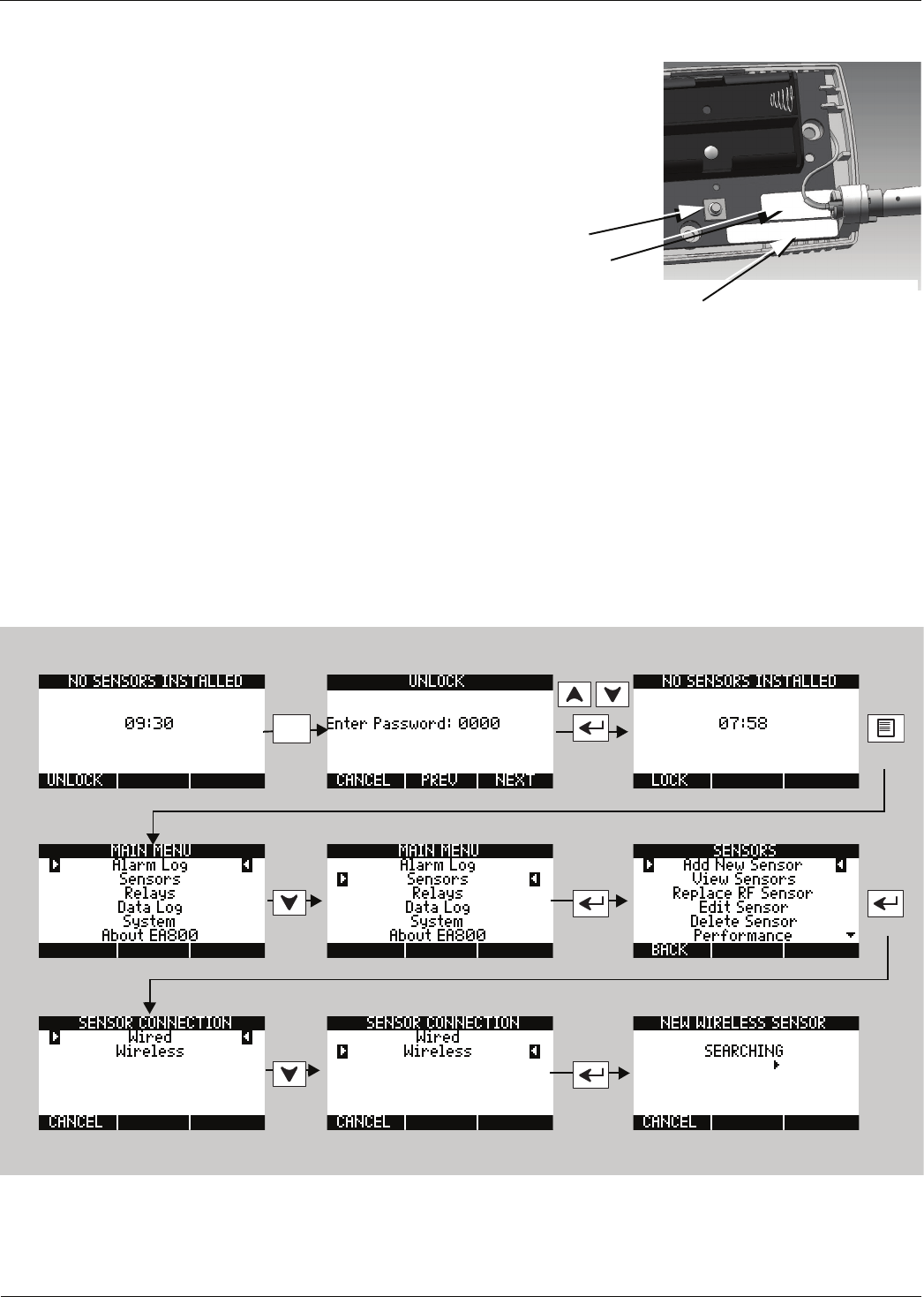
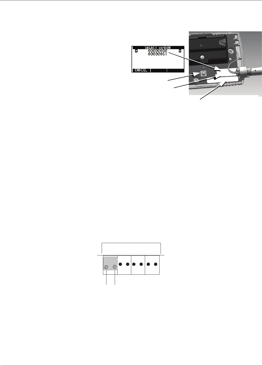
Note: Verify that the wireless sensors can communicate with the base unit as outlined in the following proce-
dure before permanently mounting them.
1. Remove the cover from the wireless sensors and
record the MAC addresses (see Figure 12) of
each wireless sensor on the Configuration
Worksheet you completed during the preparation
phase. The MAC address is printed on a label
affixed to each wireless sensor’s printed circuit
board (PCB) and is used to identify each sensor
during programming.
2. Temporarily mount the front panel of the base
unit to the mounted rear panel.
3. Connect power to the EA800. The EA800
completes its boot process and the MONITORING
or NO SENSORS INSTALLED (if there are currently
no wireless sensors installed) screen is
displayed.
4. With the wireless sensors located near the base
unit, connect power to each wireless sensor.
5. Unlock the keypad and allow the base unit to detect the wireless sensors using the following procedure.
Note: The keypad locks automatically after 30 minutes of inactivity (no key presses). If you have not finished
the detection and programming process for a sensor and this occurs, entered values are lost and you
must start the programming procedure for the sensor from the beginning. It is recommended that you
allow the base unit to identify the wireless sensors one at a time, with the sensors unmounted and in the
same location as the base unit.
RESET BUTTON
SENSOR MODEL NO.
(Example: EA-WTS = Wireless Temperature Sensor)
MAC Address Label
Figure 12 Wireless Sensor MAC Address Location
Enter
0800
F1
Example shown, set values as
appropriate for your system.
24 D-011-0152
Connecting Wired Temperature, Contact Closure, and Water Bug Sensors
Note: It may take a few minutes for the base unit to detect the wireless sensors.
At this point the NEW WIRELESS SENSOR screen is displayed and an arrow moves from left to right indicating that the
EA800 is waiting to receive sensor ID data. When the EA800 has communicated with the reachable sensors the
SELECT SENSOR screen displays a list of wireless sensors detected.
■When a sensor is detected, confirm that the ID
number shown matches the ID number on the
sensor’s label..
■If the sensors can communicate with the EA800,
their IDs appear in the list as shown in the
example at right. Do not permanently install the
sensors that appear in the list until you verify
their signal strength when you program the
wireless sensors in the system later in the
installation process.
■If the list of number(s) on the screen does not
contain the number found on the sensor's PC
board, press F1 (CANCEL) to continue the
search process.
Note: Press the Reset Button on the sensor to
restart the search process if necessary.
After the base unit has identified each wireless sensor and you have programmed it, temporarily mount it in its
desired location using tape. This allows the sensor to be relocated if necessary in order to obtain good signal
strength
Connecting Wired Temperature, Contact Closure, and Water Bug Sensors
1. Make certain the sensor's wiring is passed through the opening in the mounting plate.
2. Remove the adapter from the correct input connector header by pulling the adapter up and off of the circuit
board header connector.
3. Strip the ends of each of the sensor's wires as indicated by the gauge on adapter you just removed.
4. Insert the stripped wire ends into screw terminals of the adapter as indicated by the EA800 Wiring Diagram you
completed in the preparation phase. There is no need to observe polarity when connecting sensor wires. See
Figure 14.
Figure 14 EA800 Base Unit Wired Temperature, Contact Closure, and Water Bug Sensor Connections
5. Secure the connections using the setscrews on the adapter. Check the connection by lightly pulling on each
connection.
6. After connecting the wire ends to the adapter, align the adapter to the correct header pins as indicated by your
EA800 Wiring Diagram, and press the adapter fully onto the header connector pins.
RESET BUTTON
SENSOR MODEL NO.
(Example: EA-WTS = Wireless Temperature Sensor)
MAC Address Label
Figure 13 Wireless Sensor IDs and MAC Address Location
J6
Input 1 Input 2 Input 3 Input 4
+ (-) + (-) + (-)
+ (-)
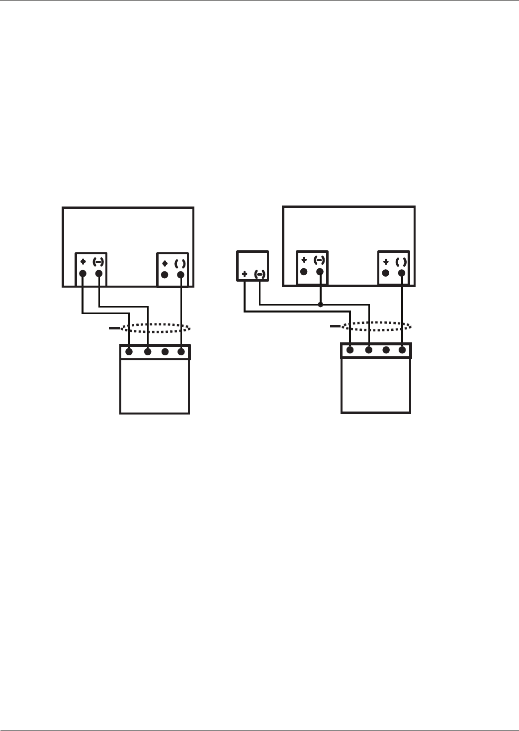
Installation
D
-
011
-
0152
25
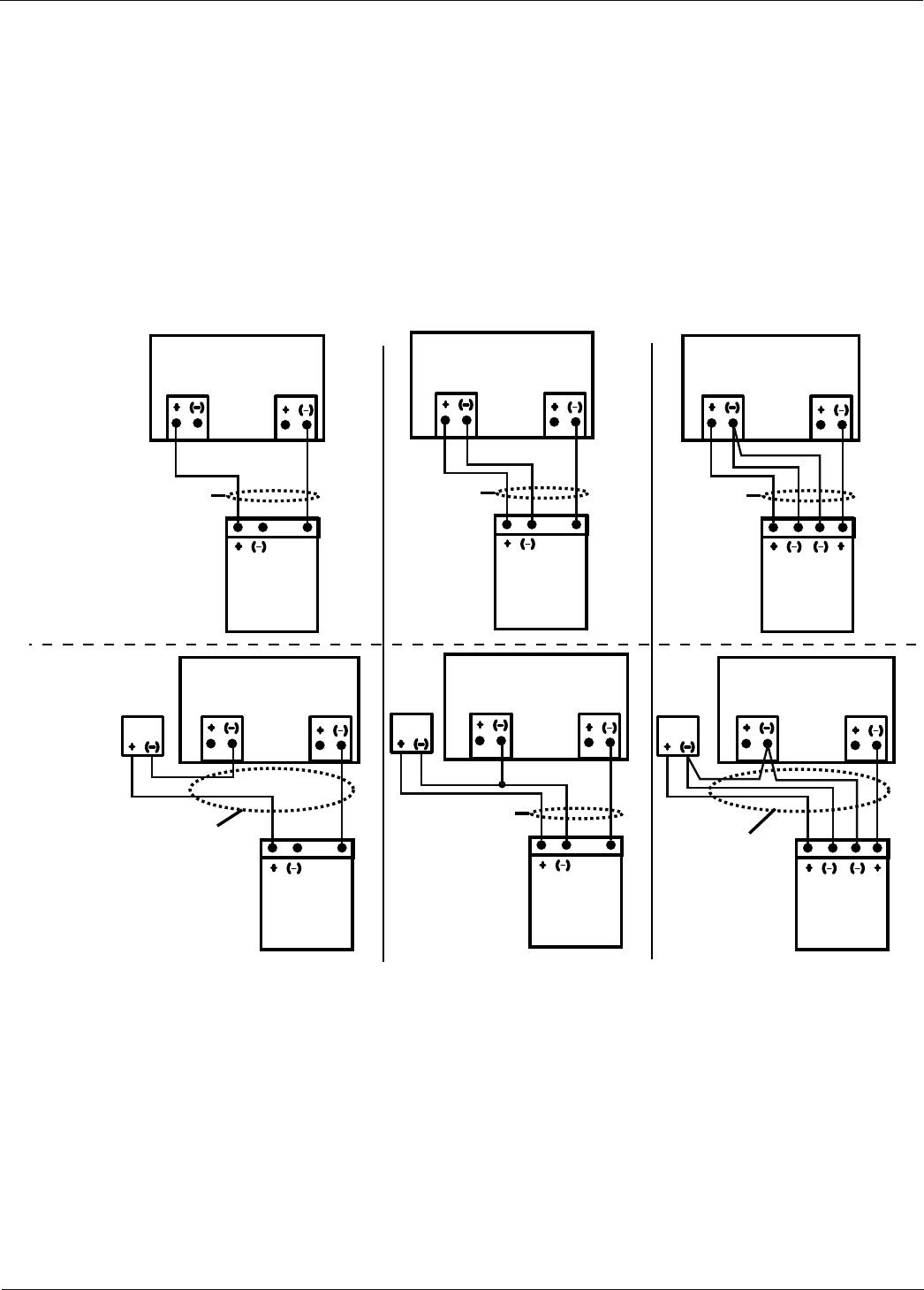
Connecting Wired HA-III+ Humidity Sensors
1. Make certain the sensor's wiring is passed through the opening in the mounting plate.
2. Remove the adapter from the correct input connector headers by pulling the adapter up and off of the circuit
board header connectors.
3. Strip the ends of each of the sensor's wires as indicated by the gauge on adapter you just removed.
4. Insert the stripped wire ends into screw terminals of the adapter as indicated by your EA800 Wiring Diagram
you completed in the preparation phase. Observe proper polarity. See Figure 15.
Figure 15 EA800 Base Unit Wired HA-III+ Sensor Connections
5. Secure the connections using the setscrews on the adapter. Check the connection by lightly pulling on each
connection.
6. After connecting the wire ends to the adapter, align the adapter to the correct header pins as indicated by your
EA800 Wiring Diagram, and press the adapter fully onto the header connector pins.
J6
Input N
User
supplied
cable
HA-III+
Connector
Power Input
GND
SINK
SOURCE
NC
NC
J5
Aux Power Out
EA800 Base Unit
J6
Input N
User
supplied
cable
HA-III+
Connector
Power Input
GND
SINK
SOURCE
NC
NC
J5
Aux Power Out
External
Power
Adapter
EA800 Base Unit
Base Unit-Powered External Adapter-Powered
26 D-011-0152
Connecting Wired 4-20mA Sensors
Connecting Wired 4-20mA Sensors
1. Make certain the sensor's wiring is passed through the opening in the mounting plate.
2. Remove the adapter from the correct input connector headers by pulling the adapter up and off of the circuit
board header connectors.
3. Strip the ends of each of the sensor's wires as indicated by the gauge on adapter you just removed.
4. Insert the stripped wire ends into screw terminals of the adapter as indicated by your EA800 Wiring Diagram
you completed in the preparation phase. Observe proper polarity. See Figure 15.
Figure 16 EA800 Base Unit Wired 4-20mA Sensor Connections
5. Secure the connections using the setscrews on the adapter. Check the connection by lightly pulling on each
connection.
6. After connecting the wire ends to the adapter, align the adapter to the correct header pins as indicated by your
EA800 Wiring Diagram, and press the adapter fully onto the header connector pins.
4-20mA Sensors
(3-wire)
EA800 Base
Unit Powered
External
Adapter
Powered
J6
Input N
User
supplied
cable
4-20mA
Transmitter
Connector
NC
J5
Aux Power Out
EA800 Base Unit
J6
Input N
User
supplied
cable
NC
J5
Aux Power Out
External
Power
Adapter
EA800 Base Unit
4-20mA
Transmitter
Connector
4-20mA
Output
4-20mA
Output
4-20mA Sensors
(2-wire)
J6
Input N
User
supplied
cable
4-20mA
Transmitter
Connector
NC
J5
Aux Power Out
EA800 Base Unit
J6
Input N
User
supplied
cable
NC
J5
Aux Power Out
External
Power
Adapter
EA800 Base Unit
4-20mA
Transmitter
Connector
4-20mA
Output
4-20mA
Output
4-20mA Sensors
(4-wire)
J6
Input N
User
supplied
cable
4-20mA
Transmitter
Connector
NC
J5
Aux Power Out
EA800 Base Unit
J6
Input N
User
supplied
cable
NC
J5
Aux Power Out
External
Power
Adapter
EA800 Base Unit
4-20mA
Transmitter
Connector

Installation
D
-
011
-
0152
27
Connecting the EA800 Alarm Outputs
1. If alarm loops will be controlled by the EA800, install all required wiring from alarm loops to the EA800
mounting location.
2. Connect the alarm loop leads to the terminal block adapter. Attach the adapter to terminals C and either NC or
NO on the appropriate circuit board header connector.
3. Repeat the previous step for each alarm loop.
4. Engage the mating tabs on the EA800 main chassis into the mounting plate upper hinges.
5. Pivot the bottom of the EA800 main chassis into closed position while aligning the retainer tabs on the main
chassis with the holes in the rear mounting plate and ensure that the wiring is not pinched, stressed, or
protruding between the chassis halves.
6. Snap the main chassis closed onto the mounting plate. When properly closed, the main chassis and mounting
plate mating surfaces are flush.
Programming
When powered-up, the EA800 is ready for programming. The following is an overview of the general process for
programming the EA800:
■View the MAIN MENU and unlock the EA800 as described in “Accessing the MAIN MENU for Programming” on
page 28.
■Set the system configuration as described in “Configuring System Parameter Settings” on page 28.
■Set the current date as described in “Setting the Current Date” on page 31.
■Set the current time as described in “Setting the Time” on page 32.
■Add the wireless sensors. See the appropriate subsection under “Adding Wireless Sensors” on page 33.
■Add the wired sensors. See the appropriate subsection under “Adding Wired Sensors” on page 43.
■Verify performance of the wireless sensors. See “Verify Wireless Signal Strength” on page 42.
■Configure the relays. See “Configuring the Relays” on page 48.
Note: When no sensors are programmed in the EA800 system, the EA800 base unit boots up with a 30-minute
delay before the alarm buzzer sounds. At this time the Alarm screen is displayed with a System Alarm
caused by the fact that no sensors have been programmed yet. To prevent the System Alarm from going
off, you must program at least 1 connected sensor into the EA800 base unit prior to the end of the
30-minute alarm time-out. If the alarm buzzer sounds press the Alarm Silence key to temporarily silence
the alarm buzzer.
CAUTION
!
If the EA800 base unit will be connected to a remote alarm panel, do not connect
the base unit to the alarm panel until after sensor connection and configuration
is complete. Connecting the remote alarm panel before configuring the EA800
sensors will result in false alarms at the remote panel.
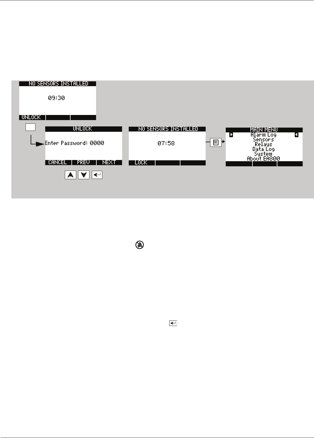
28 D-011-0152
Programming
Accessing the MAIN MENU for Programming
1. If not already powered up, apply power to the EA800 base unit. During the boot process:
■The Winland Electronics splash screen is displayed.
■The system verifies flash memory, as indicated by FLASH BOOT at the bottom of the screen.
■The About screen is displayed.
■The MONITORING screen is displayed. UNLOCK appears above the F1 soft key.
2. Follow the steps below to unlock the keypad and access the MAIN MENU screen.
Note: If the password entered was incorrect, the INVALID PASSWORD screen is displayed. If this happens, press
the OK soft key (F3) to try again. The 0800 password is a permanent password that can always be used
to unlock the base unit even if a different password has been set.
Note: Because there are no sensors programmed into the EA800 base unit the buzzer will sound when the
timer reaches 00:00 seconds. Press to temporarily silence the buzzer.
You can now access the MAIN MENU programming functions.
Configuring System Parameter Settings
Configuring the system settings consists of selecting date and time display format, setting sensor data collection
frequency, and enabling or disabling the audible alarm. The default system configuration parameter settings are
shown on page 14. To configure the system settings, do the following:
1. Unlock the base unit and access the MAIN MENU.
2. When programming, use the arrow keys, the Enter key , and the three soft keys to advance through the
menus and enter the appropriate information.
F1
0800
Example shown, set values as
appropriate for your system.
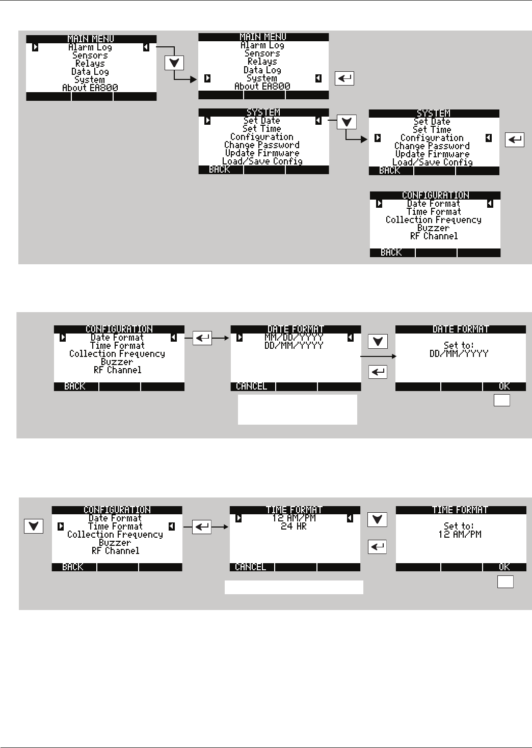
Installation
D
-
011
-
0152
29
3. Enter the SYSTEM menu and then select the CONFIGURATION menu as shown below.
:
4. The default date format is MM/DD/YYYY. If you prefer DD/MM/YYYY format, from the CONFIGURATION menu,
set the DATE FORMAT as appropriate for your region.
5. Press F3 to confirm your selection. When the CONFIGURATION menu is displayed, skip TIME FORMAT if you want
to use the default time format of 24-hour clock. If you prefer a 12-hour AM/PM clock, set the time format as
follows:
:
6. Press F3 to confirm your selection. When the CONFIGURATION menu is displayed, select and set
COLLECTION FREQUENCY as shown below. Collection Frequency determines how often the base unit collects
data from the sensors.
F3
Choose setting for your region.
F3
Choose setting for your region.
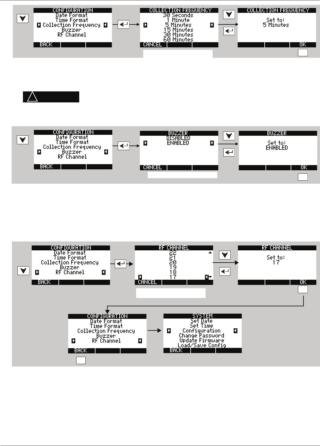
30 D-011-0152
Programming
7. Press F3 to confirm your selection. When the CONFIGURATION menu is displayed, select and set BUZZER as
shown below. The BUZZER setting enables/disables the audible alarm buzzer.
8. Press F3 to confirm your selection. When the CONFIGURATION menu is displayed, select and set RF CHANNEL as
shown below. The RF CHANNEL setting determines the RF frequency at which the wireless sensor(s) and base
station communicate.
Note: If the RF channel is changed after one or more wireless sensors have been added to the system, all
wireless sensors must be reset.
9. Press F3 to confirm your selection. When the CONFIGURATION menu is displayed, press F1 to return to the MAIN
MENU.
You have configured the EA800 system settings. Proceed to the next section to set the time and date.
WARNING
!
Selecting DISABLED for this parameter turns the audible alarm buzzer off
completely. No audible alarm tone will sound when an alarm occurs if
DISABLED is selected.
F3
Choose appropriate setting.
F3
Choose appropriate setting.
F3
F1
Choose appropriate setting.
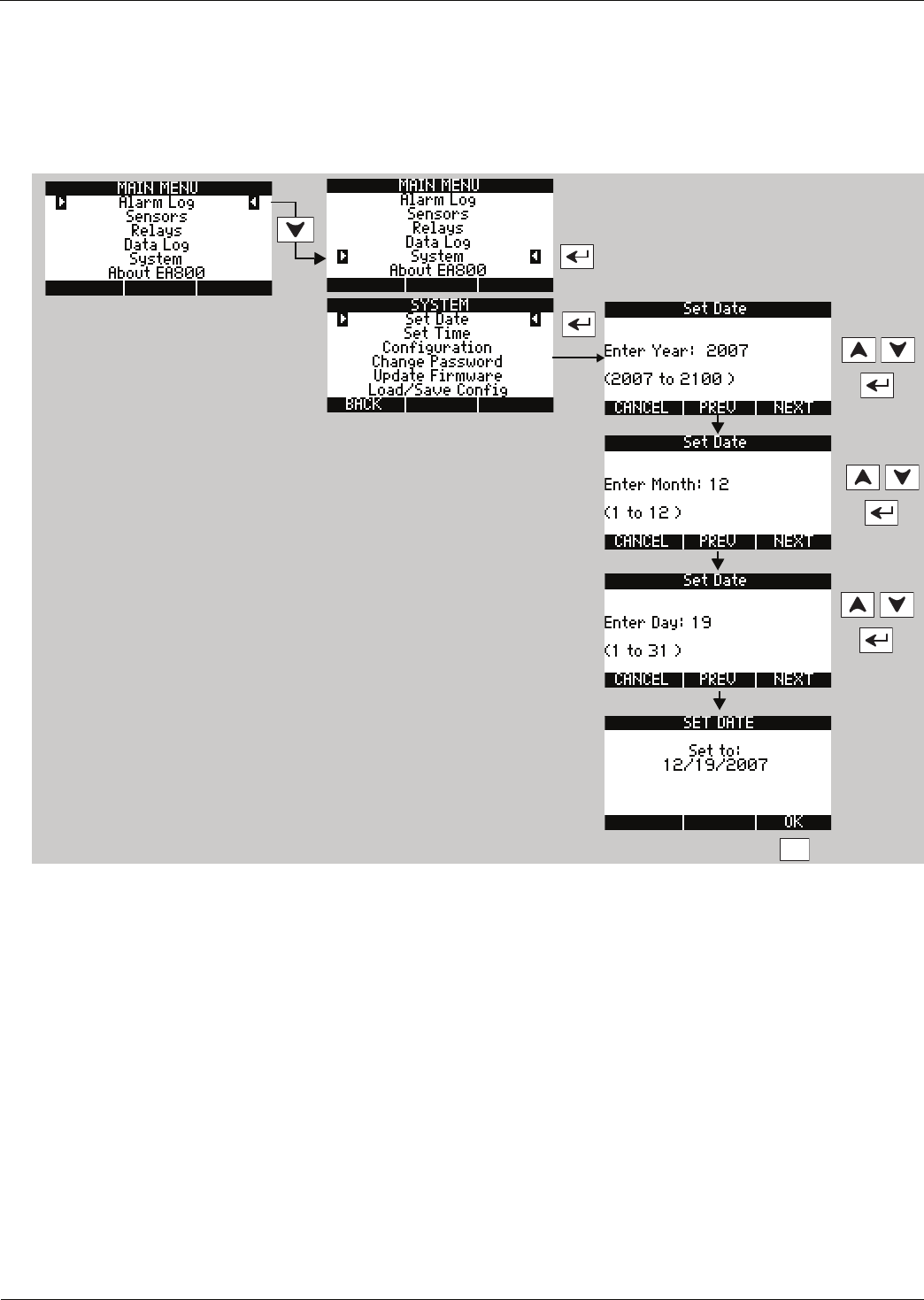
Installation
D
-
011
-
0152
31
Setting the Current Date
Unlock the EA800 to continue programming if necessary. See “Accessing the MAIN MENU for Programming” on
page 28. From the MAIN MENU, use the arrow keys to select SYSTEM, then select Set Date and set the current date
as shown below.
Note: To go back or to skip a step, press the PREV (F2) or NEXT (F3) keys. To cancel, press F1.
F3
Example shown, set values as
appropriate for your system.
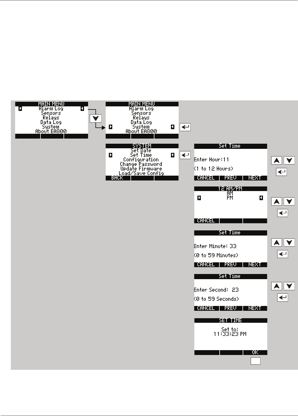
32 D-011-0152
Programming
Setting the Time
Unlock the EA800 to continue programming if necessary. See “Accessing the MAIN MENU for Programming” on
page 28.
From the MAIN MENU, use the arrow keys to select SYSTEM, then select Set Time and set the current time as shown
below. If your region uses Daylight Savings Time and you want the EA800 to display the correct time, you must
change the time setting manually when Daylight Savings Time starts and ends.
Note: To advance the cursor to the next digit when entering numeric values, press the NEXT (F3) key. To can-
cel, press F1. Use the arrow keys to increase or decrease the numeric value.
Note: The following menus are for setting time in 12-hour format. Follow the similar on-screen prompts to set
time in 24-hour (military time) format.
You have set the time for the EA800. Proceed to the next section to add wireless sensors. If you are not adding
wireless sensors, skip to “Adding Wired Sensors” on page 43.
F3
Example shown, set values as
appropriate for your system.
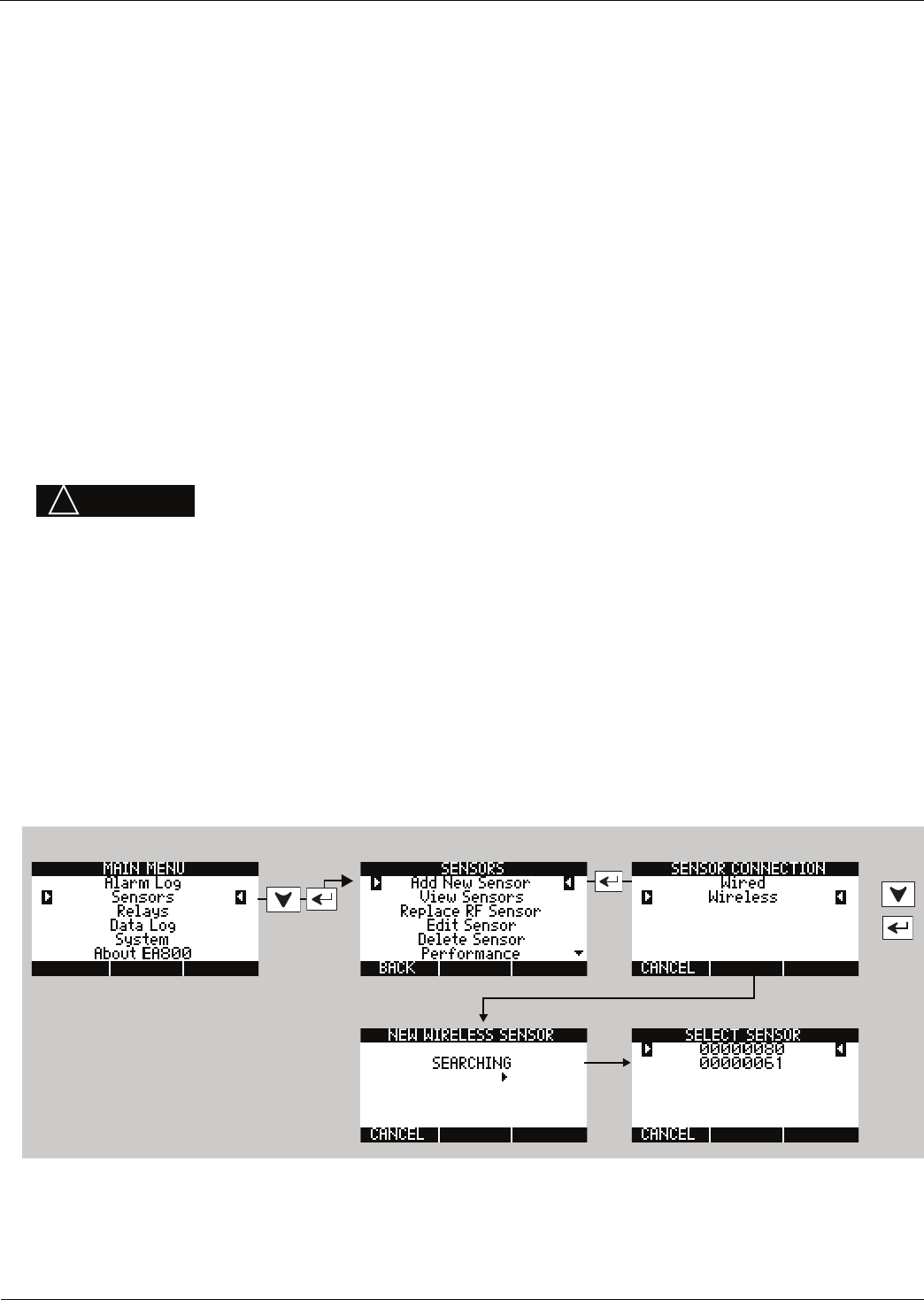
Installation
D
-
011
-
0152
33
Adding Wireless Sensors
Go to the appropriate section for the wireless sensor to be added:
■Wireless Temperature Sensor: See “Adding a Wireless Temperature Sensor” on page 33
■Wireless Humidity Sensor: See “Adding a Wireless Humidity Sensor” on page 37
■Wireless Multi-Function Sensor: See “Adding a Wireless Multi-Function Sensor Using a Wired Temperature
Sensor” on page 35. Multi-function sensor may be programmed to operate with the following types of wired
sensors:
•Low Temperature Sensor - Blue Thermistor Probes: See “Adding a Wireless Multi-Function Sensor
Using a Wired Temperature Sensor” on page 35.
•High Temperature Sensor - Red Thermistor Probes: See “Adding a Wireless Multi-Function Sensor
Using a Wired Temperature Sensor” on page 35.
•Ultra Low Temperature Sensor - White Thermistor Probes: See “Adding a Wireless Multi-Function
Sensor Using a Wired Temperature Sensor” on page 35.
•WaterBug Sensor: See “Adding a Wireless Multi-Function Sensor Using a Wired WaterBug Sensor” on
page 38.
•N.O. Contact: See “Adding a Wireless Multi-Function Sensor Using a Wired Contact Closure Sensor” on
page 40.
•N.C. Contact: See “Adding a Wireless Multi-Function Sensor Using a Wired Contact Closure Sensor” on
page 40.
Adding a Wireless Temperature Sensor
1. Unlock the base unit if necessary to continue programming. See “Accessing the MAIN MENU for
Programming” on page 28.
2. Select SENSORS from the MAIN MENU and follow the steps in the following diagram.
3. After you press the ENTER key, the NEW WIRELESS SENSOR screen is displayed. The EA800 searches for new
wireless sensors, indicated by an arrow that moves from left to right across the screen. When an available
wireless sensor has been detected, it is listed in the SELECT SENSOR screen as shown below.
4. Confirm that all new (unprogrammed) wireless sensors are displayed on the SELECT SENSOR screen, use the
arrow keys to select the sensor to be configured, then follow the prompts to configure all screens for that
sensor.
CAUTION
!
If the EA800 base unit will be connected to a remote alarm panel, do not connect
the base unit to the alarm panel until after sensor connection and configuration
is complete. Connecting the remote alarm panel before configuring the EA800
sensors will result in false alarms at the remote panel.
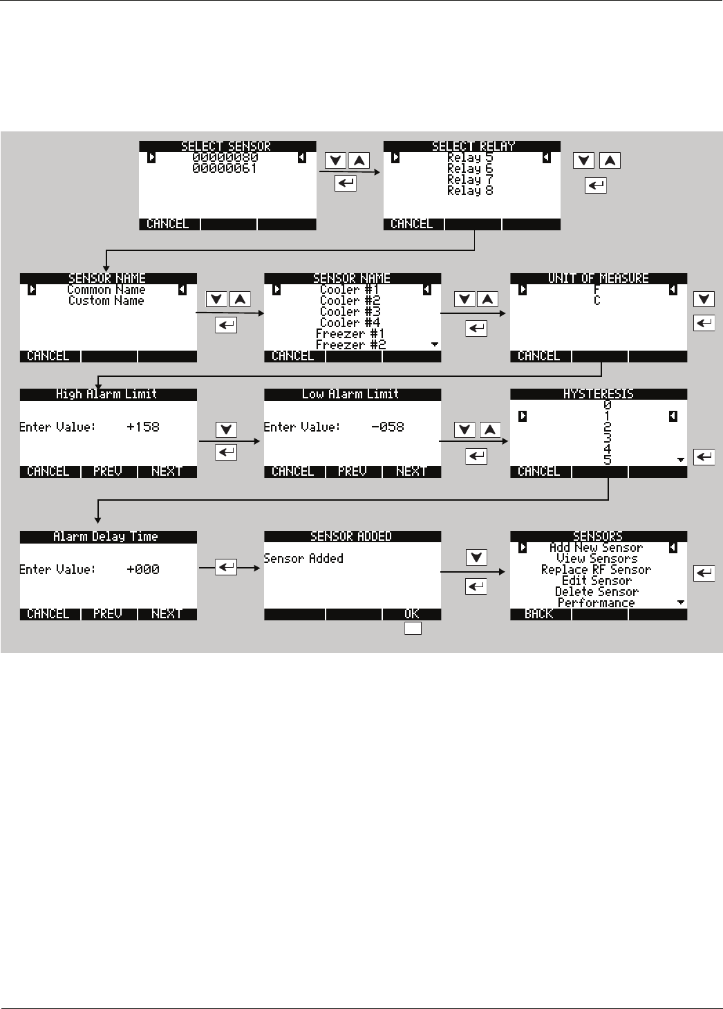
34 D-011-0152
Adding Wireless Sensors
Note: To enter numeric values, use the arrow keys. To advance the cursor to the next digit when entering
numeric values, press the NEXT soft key (F3). To return to a previous digit, press the PREV soft key (F2).
The Hysteresis setting helps prevent alarms from being set and reset continually if the environment is at or near the
alarm set point by providing an acceptable variance. For example, if HYSTERESIS is set at 1 and the sensor High
Alarm Limit is set at +158, the sensor reading must decrease to +157 (+158 minus 1) in order for the alarm condition
to reset to a no-alarm condition.
Note: Repeat this sensor for each wireless temperature sensor you need to program. When you have finished
programming wireless temperature sensors, proceed to the section appropriate for the other types of
wireless sensors to be added.
F3
Example shown, set
values as appropriate for
your system.
Installation
D
-
011
-
0152
35
Adding a Wireless Multi-Function Sensor Using a Wired Temperature Sensor
Wireless multi-function sensors are physically connected to wired sensors located elsewhere and provide a
transmitter to send the signals monitored by the wired sensor to the base unit. To add a wireless multi-function
sensor, do the following:
1. Unlock the base unit if necessary to continue programming. See “Accessing the MAIN MENU for
Programming” on page 28.
2. Select SENSORS from the MAIN MENU and follow the steps in the following diagram.
3. After you press the ENTER key, the NEW WIRELESS SENSOR screen is displayed. The EA800 searches for new
wireless sensors, indicated by an arrow that moves from left to right across the screen. When an available
wireless sensor has been detected, it is listed in the SELECT SENSOR screen as shown below.
4. Use the arrow keys to select the wireless multifunction sensor to be configured, then follow the prompts to
configure all screens for that sensor.
Follow the procedure shown on the next page to add a temperature sensor. The procedure shows a wired Blue
temperature sensor, but is applicable to the wired Red and White temperature sensors as well.
The Hysteresis setting helps prevent alarms from being set and reset continually if the environment is at or near
the alarm set point by providing an acceptable variance. For example, if HYSTERESIS is set at 1 and the sensor High
Alarm Limit is set at +158, the sensor reading must decrease to +157 (+157 minus 1) in order for the temperature
alarm to reset to a no-alarm condition.
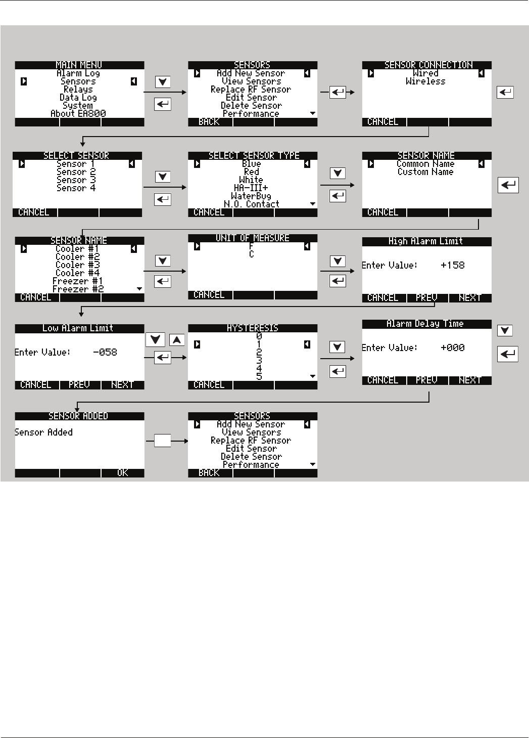
36 D-011-0152
Adding Wireless Sensors
When setting numeric values, use the arrow keys to change the value. Use the PREV and NEXT soft keys to move
the cursor to the next or previous digit. Press the ENTER key to enter the value.
This is the start screen for the next
sensor to be added, if any.
F3
Example shown, set values as
appropriate for your system.
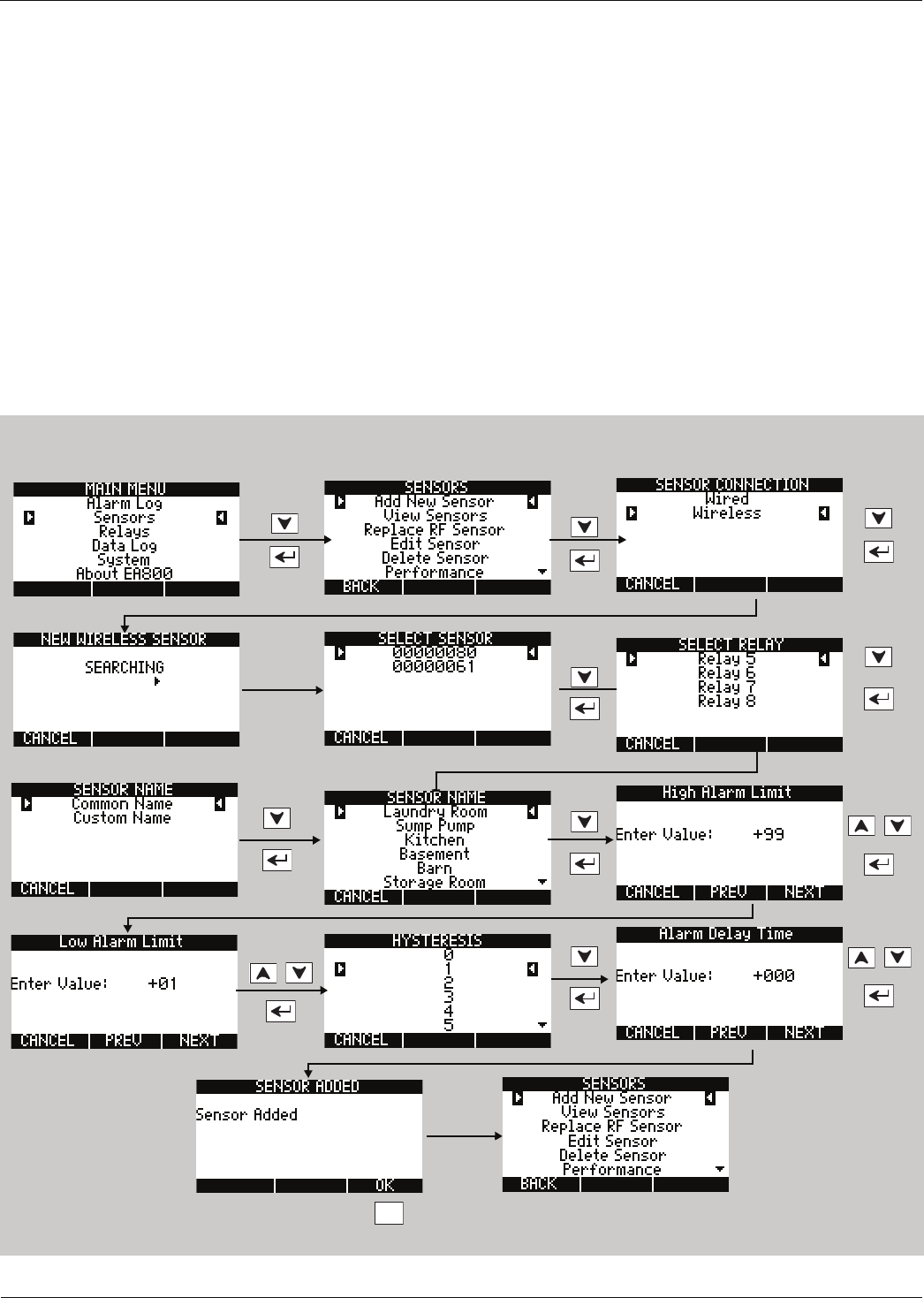
Installation
D
-
011
-
0152
37
Adding a Wireless Humidity Sensor
The Hysteresis setting helps prevent alarms from being set and reset continually if the environment is at or near
the alarm set point by providing an acceptable variance. For example, if HYSTERESIS is set at 1 and the sensor High
Alarm Limit is set at +95, the sensor reading must decrease to +94 (+95 minus 1) in order for the humidity alarm
condition to reset to a no-alarm condition.
The humidity sensor also allows you to configure an alarm delay time if desired.
1. Unlock the base unit if necessary to continue programming. See “Accessing the MAIN MENU for
Programming” on page 28.
2. Select SENSORS from the MAIN MENU and follow the steps in the following diagram.
3. After you press the ENTER key, the NEW WIRELESS SENSOR screen is displayed. The EA800 searches for new
wireless sensors, indicated by an arrow that moves from left to right across the screen. When an available
wireless sensor has been detected, it is listed in the SELECT SENSOR screen as shown below.
4. Use the arrow keys to select the sensor to be configured, then follow the prompts to configure all screens for
that sensor as shown in the following diagram.
F3
This is the start screen for the next
sensor to be added, if any.
Example shown, set values as
appropriate for your system.

38 D-011-0152
Adding Wireless Sensors
Adding a Wireless Multi-Function Sensor Using a Wired WaterBug Sensor
Wireless multi-function sensors are physically connected to wired sensors located elsewhere and provide a
transmitter to send the signals monitored by the wired sensor to the base unit. To add a wireless multi-function
sensor, do the following:
1. Unlock the base unit if necessary to continue programming. See “Accessing the MAIN MENU for
Programming” on page 28.
2. Select SENSORS from the MAIN MENU and follow the steps in the following diagram.
3. After you press the ENTER key, the NEW WIRELESS SENSOR screen is displayed. The EA800 searches for new
wireless sensors, indicated by an arrow that moves from left to right across the screen. When an available
wireless sensor has been detected, it is listed in the SELECT SENSOR screen as shown below.
4. Use the arrow keys to select the wireless multifunction sensor to be configured, then follow the prompts to
configure all screens for that sensor.
To add a wireless WaterBug sensor to the system perform the following procedure.
1. Unlock the base unit if necessary to continue programming. See “Accessing the MAIN MENU for
Programming” on page 28.
2. Select SENSORS from the MAIN MENU and follow the steps in the following diagram.
3. After you press the ENTER key, the NEW WIRELESS SENSOR screen is displayed. The EA800 searches for new
wireless sensors, indicated by an arrow that moves from left to right across the screen. When an available
wireless sensor has been detected, it is listed in the SELECT SENSOR screen as shown below.
4. Use the arrow keys to select the sensor to be configured, then follow the prompts to configure all screens for
that sensor as shown in the following diagram.

Installation
D
-
011
-
0152
39
F3
This is the start screen for the next
sensor to be added, if any.
Example shown, set values as
appropriate for your system.
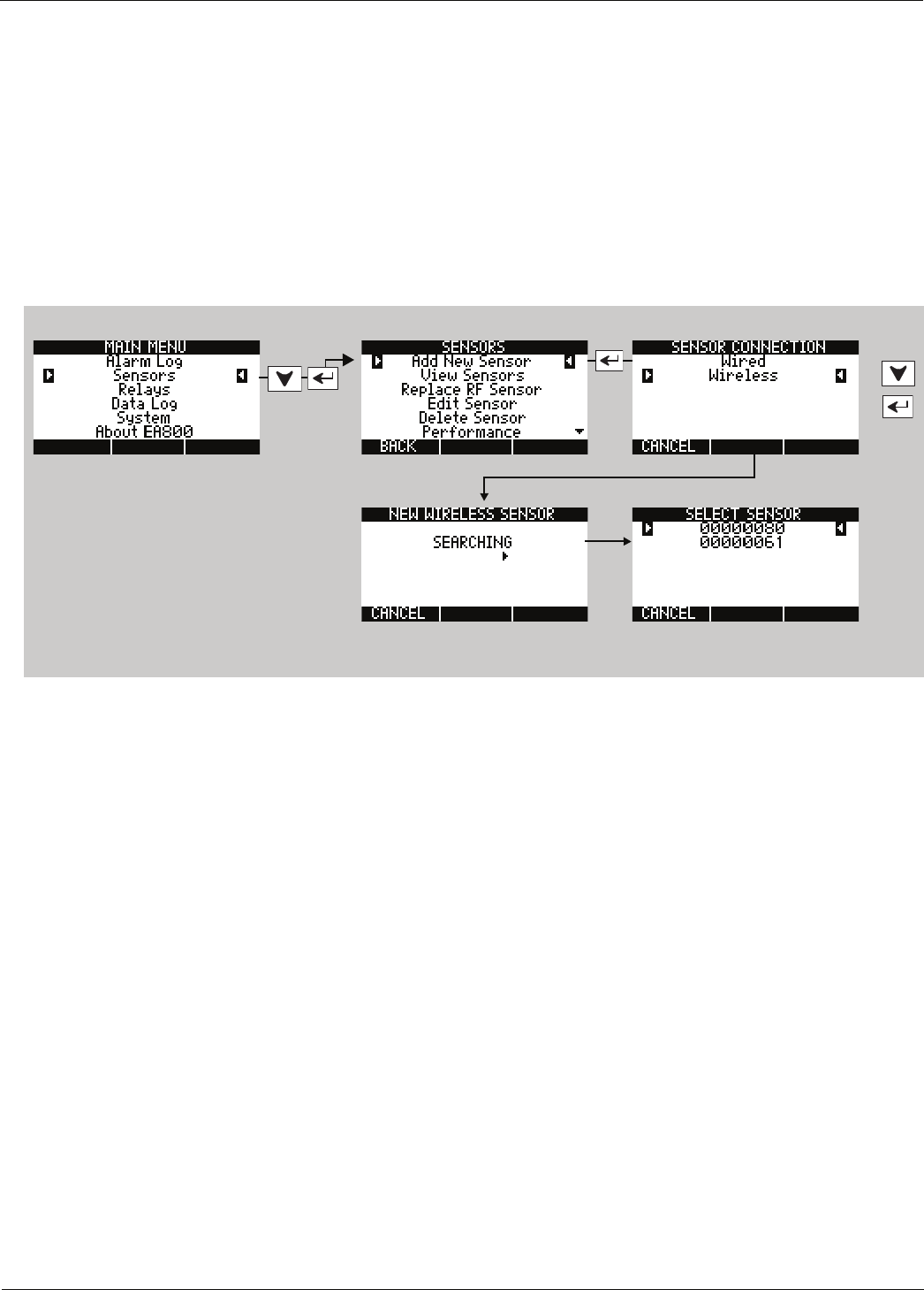
40 D-011-0152
Adding Wireless Sensors
Adding a Wireless Multi-Function Sensor Using a Wired Contact Closure Sensor
Wireless multi-function sensors are physically connected to wired sensors located elsewhere and provide a
transmitter to send the signals monitored by the wired sensor to the base unit. To add a wireless multi-function
sensor, do the following:
1. Unlock the base unit if necessary to continue programming. See “Accessing the MAIN MENU for
Programming” on page 28.
2. Select SENSORS from the MAIN MENU and follow the steps in the following diagram.
3. After you press the ENTER key, the NEW WIRELESS SENSOR screen is displayed. The EA800 searches for new
wireless sensors, indicated by an arrow that moves from left to right across the screen. When an available
wireless sensor has been detected, it is listed in the SELECT SENSOR screen as shown below.
4. Use the arrow keys to select the wireless multifunction sensor to be configured, then follow the prompts to
configure all screens for that sensor.
To add a wireless multi-function contact closure sensor to the system perform the following procedure. The
procedure shown is for a normally open (N.O.) contact closure sensor but is essentially the same for the N.C.
wireless contact closure sensor.
1. Unlock the base unit if necessary to continue programming. See “Accessing the MAIN MENU for
Programming” on page 28.
2. Select SENSORS from the MAIN MENU and follow the steps in the following diagram.
3. After you press the ENTER key, the NEW WIRELESS SENSOR screen is displayed. The EA800 searches for new
wireless sensors, indicated by an arrow that moves from left to right across the screen. When an available
wireless sensor has been detected, it is listed in the SELECT SENSOR screen as shown below.
4. Use the arrow keys to select the sensor to be configured, then follow the prompts to configure all screens for
that sensor as shown in the following diagram.
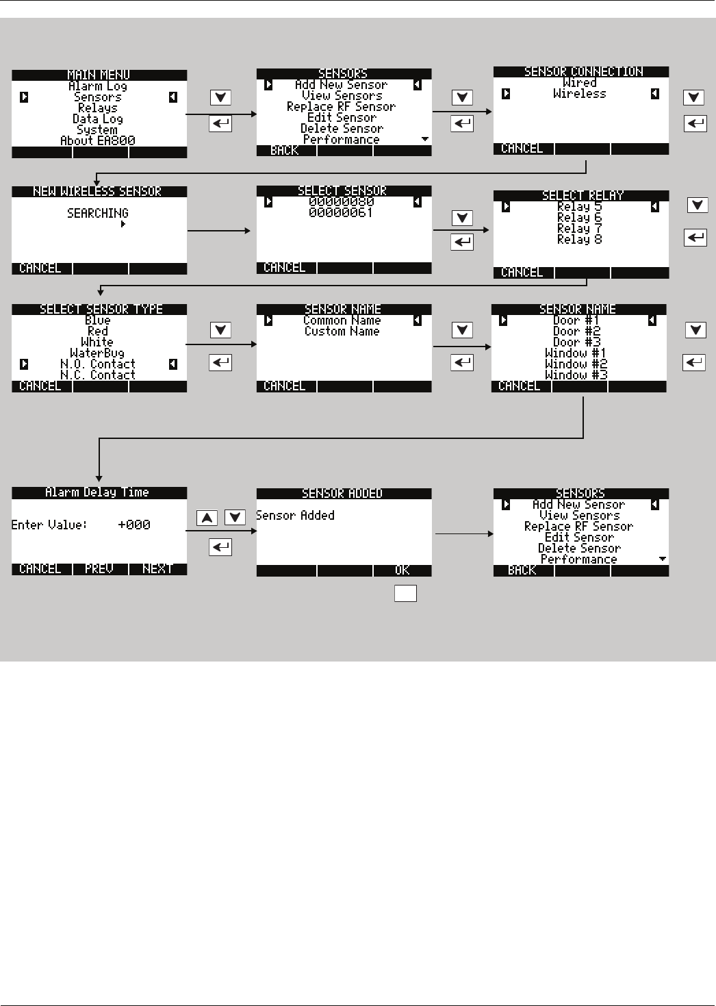
Installation
D
-
011
-
0152
41
F3
This is the start screen for the next
sensor to be added, if any.
Select N.O. Contact or N.C. Contact
as appropriate.
Example shown, set values as
appropriate for your system.
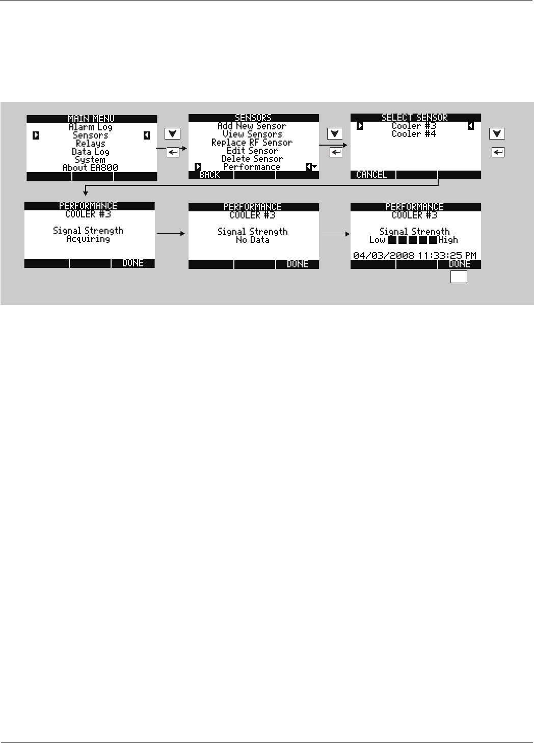
42 D-011-0152
Adding Wireless Sensors
Verify Wireless Signal Strength
After temporarily mounting the wireless sensors in the desired location, verify the signal strength at the base unit by
performing the following procedure to verify the signal strength of each programmed wireless sensor. It may take
as long as 30 seconds to acquire the current signal strength.
Perform the following procedure to verify the signal strength of each programmed wireless sensor.
If No Data is displayed in place of bars, it indicates that recent signal strength information has not been received. If
this persists for 1-2 minutes without displaying any performance bars, it is a strong indication that your sensor is
placed out of range with the base unit.
If fewer than two bars are shown, it is recommended that the sensor be relocated to obtain a better signal. Refer to
the instruction sheet included with the wireless sensor for details on ensuring optimum signal strength.The wireless
environment can change throughout the day because of other activity in the vicinity. It is therefore important to
verify the signal strength by approximating the worst case scenario the RF signal may encounter.
F3
No Data is displayed until a signal is received and then the
signal strength is displayed as shown in the last screen.
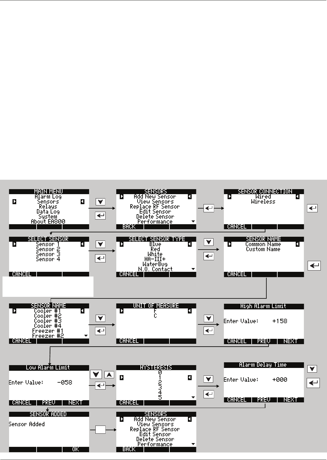
Installation
D
-
011
-
0152
43
Adding Wired Sensors
■Low temperature sensors - Blue Thermistor Probes: See “Adding a Wired Temperature Sensor” on page 43.
■High temperature sensors - Red Thermistor Probes: See “Adding a Wired Temperature Sensor” on page 43.
■Ultra Low temperature sensors - White Thermistor Probes: See “Adding a Wired Temperature Sensor” on
page 43.
■HA-III+ humidity sensor: See “Adding a Wired HA-III+ Humidity Sensor” on page 44.
■WaterBug sensor: See “Adding a Wired WaterBug Sensor” on page 45.
■N.O. Contact: See “Adding a Wired Contact Closure Sensor” on page 46.
■N.C. Contact: See “Adding a Wired Contact Closure Sensor” on page 46.
■4-20 mA: See “Adding a 4-20mA Sensor” on page 47.
Adding a Wired Temperature Sensor
The procedure shown below adds a wired Blue temperature sensor, but is applicable to the wired Red and White
temperature sensors as well.
The Hysteresis setting helps prevent alarms from being set and reset continually if the environment is at or near
the alarm set point by providing an acceptable variance. For example, if HYSTERESIS is set at 1 and the sensor High
Alarm Limit is set at +158, the sensor reading must decrease to +157 (+157 minus 1) in order for the temperature
alarm to reset to a no-alarm condition.
When setting numeric values, use the arrow keys to change the value. Use the PREV and NEXT soft keys to move
the cursor to the next or previous digit. Press the ENTER key to enter the value.
This is the start screen for the next
sensor to be added, if any.
F3
NOTE: Select the sensor number that
matches the input number used by the
sensor, or an alarm may result.
Example values are shown, Set all limit
values as appropriate for your system.
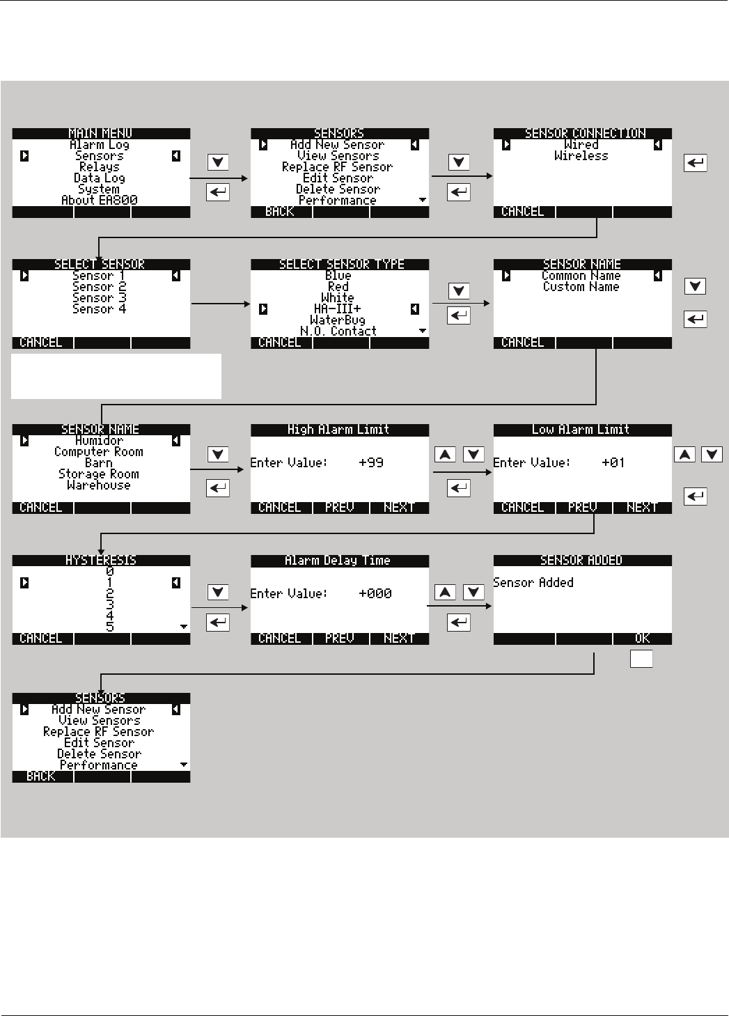
44 D-011-0152
Adding Wired Sensors
Adding a Wired HA-III+ Humidity Sensor
To add an HA-III+ humidity sensor perform the following procedure.
F3
This is the start screen for the next
sensor to be added, if any.
NOTE: The sensor number must match
the input number (J6 ) used by the
sensor or an alarm may result.
Example shown, set values as
appropriate for your system.
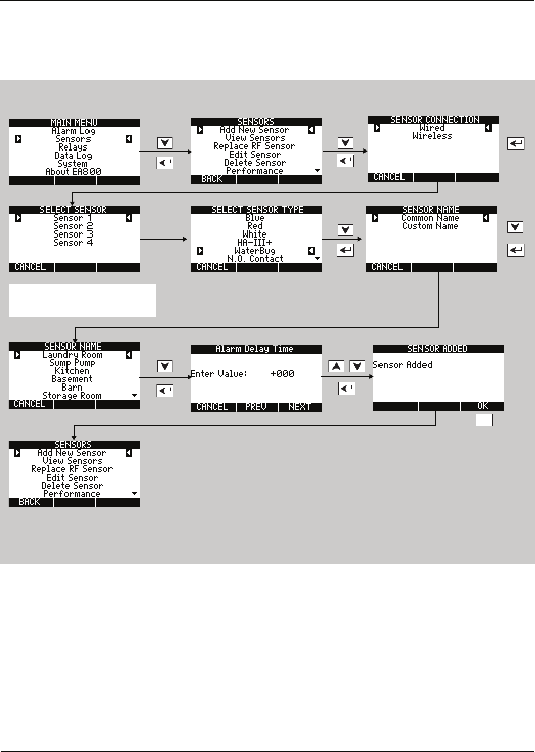
Installation
D
-
011
-
0152
45
Adding a Wired WaterBug Sensor
To add a WaterBug sensor perform the following procedure:
Note: A supervised WaterBug sensor must be used.
F3
This is the start screen for the next
sensor to be added, if any.
NOTE: The sensor number must
match the input number (J6 ) used by
the sensor or an alarm may result.
Example shown, set values as
appropriate for your system.
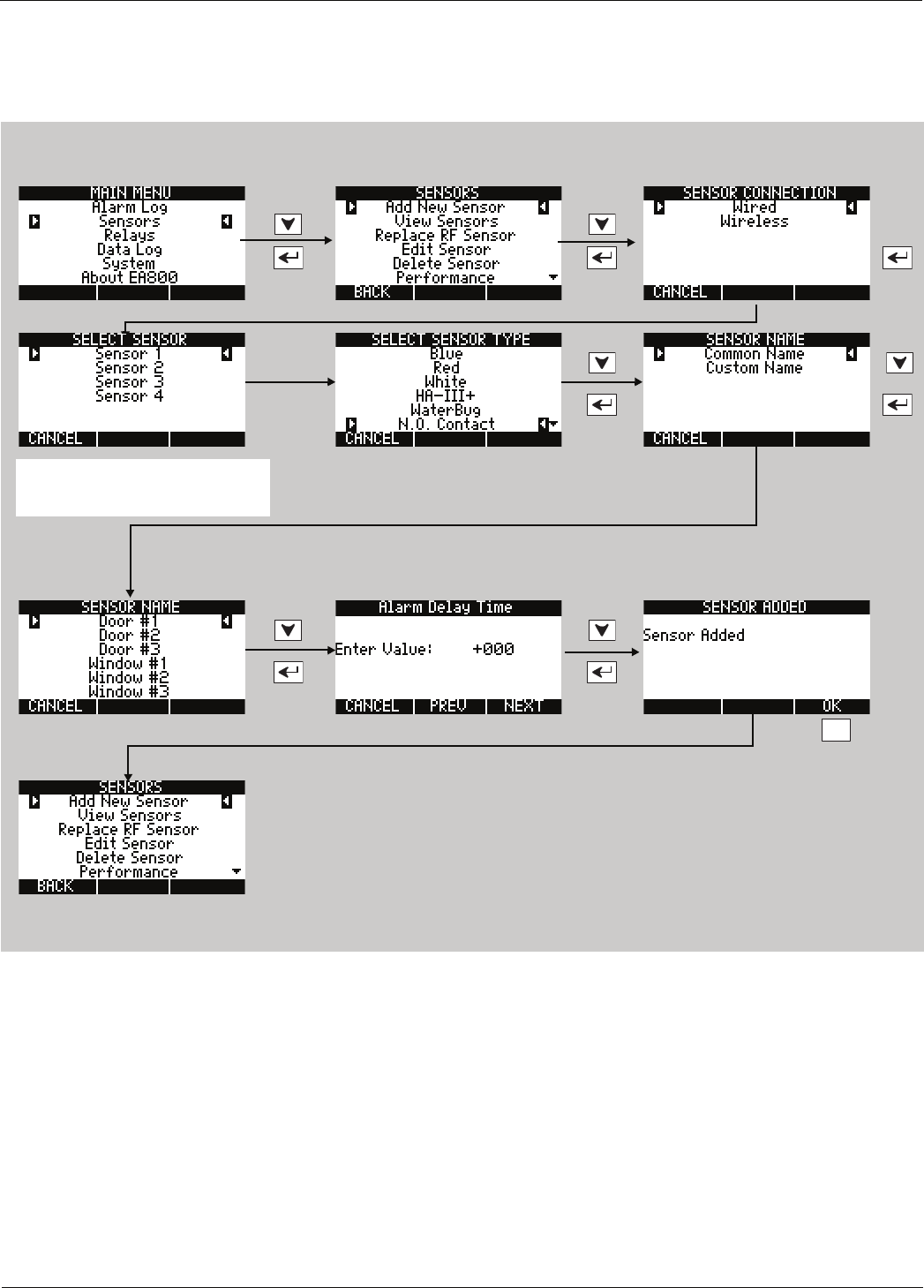
46 D-011-0152
Adding Wired Sensors
Adding a Wired Contact Closure Sensor
The following procedure shown adds a N.O. contact closure sensor but is the same for N.C. contact closure
sensor.
F3
This is the start screen for the next
sensor to be added, if any.
Select N.O. Contact or N.C. Contact
as appropriate.
NOTE: The sensor number must
match the input number (J6 ) used by
the sensor or an alarm may result.
Example shown, set values as
appropriate for your system.
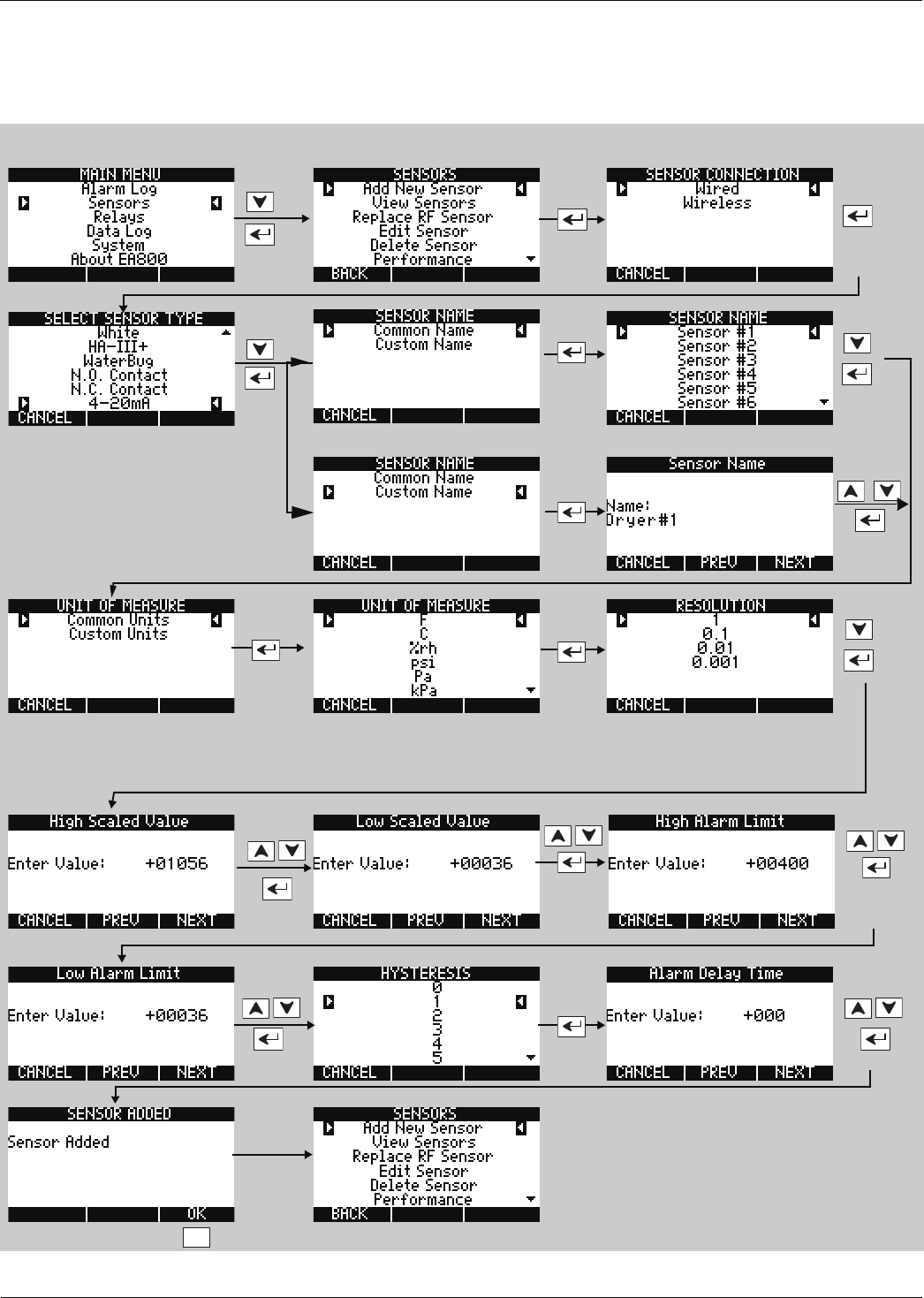
Installation
D
-
011
-
0152
47
Adding a 4-20mA Sensor
To add a 4-20mA sensor, perform the following procedure. There are some additional parameters to configure with
this type of sensor, including Unit of Measure and Resolution. 4-20mA sensors can be used for monitoring a variety
of conditions because the measured value corresponds to a current level, which is configured to represent the
conditions being monitored. Follow the steps outlined below to program a 4-20mA sensor.
F3
OR
Example shown, set values as
appropriate for your system.
High and Low Scaled Value are identified on the sensor as the sensing 'range'. It is important to
know this range before selecting the resolution. Low Scaled Value is the lowermost value or the
value equivalent to 4mA. High Scaled Value is the uppermost value or the value equivalent to
20mA indicated on the sensor. See Table 11 on page 14 for available resolution values.

48 D-011-0152
Configuring the Relays
Configuring the Relays
When all sensors have been added, you must configure the relays so that the outputs indicate the monitored
conditions correctly. Perform the following procedure to configure all relays used:
Note: The default relay settings are:
•Relays 1-8 (Active Condition = Alarm Only);
•Aux Relay (Active Condition = Alarm or Warning);
•All Relays (No Alarm - Relay State = De-Energized)
If these defaults are acceptable, it is not necessary to configure the relays.
OR
F3
OR
F3
OR
Repeat this procedure to configure the next relay.
Return to the Home screen when you have configured all
relays.
To create a backup copy of the complete configuration, see
“Saving Configuration Settings” on page 66.
F3
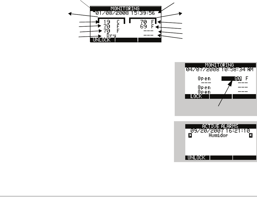
D
-
011
-
0152
49
Operation
This chapter provides instructions for doing the following:
■“Monitoring Environmental Conditions” on page 49
■“Viewing Sensor Settings” on page 50
■“Viewing Active Alarms” on page 50
■“Viewing the Alarm Log” on page 51
■“Viewing Pending Alarm Information” on page 51
■“Viewing Limit Settings” on page 52
■“Viewing the Event Log” on page 52
■“Viewing the Sensor Log” on page 53
■“Viewing Firmware Information” on page 53
■“Viewing RF Information” on page 54
Monitoring Environmental Conditions
The current environmental conditions measured by each sensor connected to the EA800 base unit are shown on
the home screen. Depending on the current sensor status the home screen may be one of the following screens:
■MONITORING screen: This screen is shown when there are no active alarms or pending alarms. This screen
displays the current readings from all programmed sensors as shown in the example below.
Note: Dashes indicate that a sensor has not been programmed yet.
■MONITORING screen with pending alarm. A pending alarm indicates that
a sensor has exceeded the low or high limits but that the condition has
not exceeded the programmed delay (0 to 120 minutes). When an
alarm is pending, the sensor’s reading is displayed in reverse text as
shown in the example for wired sensor 2.
If conditions in the sensor’s area return to the non-alarm state within
the alarm delay time, the text returns to normal. If conditions remain
outside the programmed sensor alarm limits for longer than the delay
time, the screen changes to the ACTIVE ALARMS screen below.
■.ACTIVE ALARMS Screen: This screen is displayed when conditions
monitored by any programmed sensor exceed one of its programmed
limits for longer than the programmed delay period. Only the active
alarm(s) is displayed as shown in the example below. See “Viewing
Active Alarms” on page 50 for the procedure to access alarm
information
This column shows
environmental readings
for wireless sensors 5-8.
This column shows
environmental readings
for wired sensors 1-4.
Sensor 1
Sensor 2
Sensor 3
Sensor 4
Current Date Current Time
Sensor 5
Sensor 6
Sensor 7 (not installed)
Sensor 8 (not installed)
Pending alarm
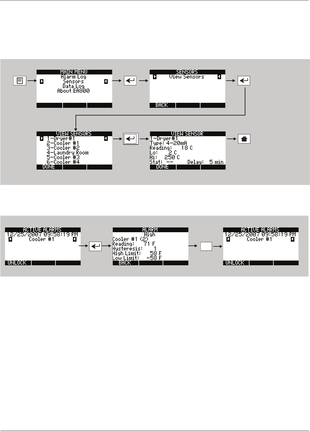
50 D-011-0152
Viewing Sensor Settings
Viewing Sensor Settings
You can view the readings of each installed sensor on the MONITORING screen. To view details of a sensor’s
programmed settings and current readings on one screen perform the procedure shown below.
Note: The MAIN MENU screen shown in the example procedure is displayed when the system is locked. Sensor
settings may also be viewed when the system is unlocked.
Use the arrow keys to highlight the desired menu item.
Viewing Active Alarms
To view the current readings of a sensor with an active alarm:
There are six conditions that may be shown in the alarm screen:
■Comm: Indicates that the wireless sensor is not communicating with the EA800.
■High: The sensor's current reading is greater than the programmed high threshold.
■Low: The sensor's current reading is less than the programmed low threshold.
■Batt: The sensor's battery is low.
■Cut: Supervised water sensors only: cable is cut or disconnected.
■Fail: Indicates that the sensor reading is exceeding the known range of the sensor.
More than one alarm condition may be displayed. For example, if a wireless sensor detects a high reading and
then stops communicating with the base unit, the alarm log will indicate a Comm, High alarm. This type of alarm
can be logged only if the high reading occurred prior to the communication failure.
F1
to exit
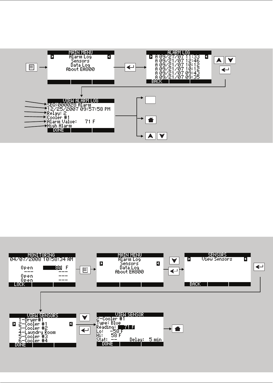
Operation
D
-
011
-
0152
51
Viewing the Alarm Log
This alarm log is a quick view of the 20 most recent alarms. Up to 100 alarms can be reviewed by selecting Data
Log from the MAIN MENU, then selecting View Alarm Log. To review the alarm history and review a specific alarm
stored in the log, perform the following procedure.
Note: The MAIN MENU screen shown in the example procedure is displayed when the system is locked. This
alarm log may also be viewed when the system is unlocked.
The View Alarm Log lines provide the following information:
■Line 1: Sequence number. Identifies the alarm in the log list.
■Line 2: Date and time the alarm was logged
■Line 3: The relay connected to the sensor that logged the alarm condition
■Line 4: The name of the sensor that logged the alarm condition
■Line 5: The sensor's reported value that generated the alarm
■Line 6: The alarm type or the clearing of alarm type
Viewing Pending Alarm Information
To view the current readings of a sensor that is in the pending alarm state perform the following procedure:
F1
When done reviewing the current
sensor readings and return to the
Alarm Log.
Line 1
Line 2
Line 3
Line 4
Line 5
Line 6
To return to Active Alarm
or Monitoring screen.
To view previous or next
alarms
To return to Active Alarm
or Monitoring screen.
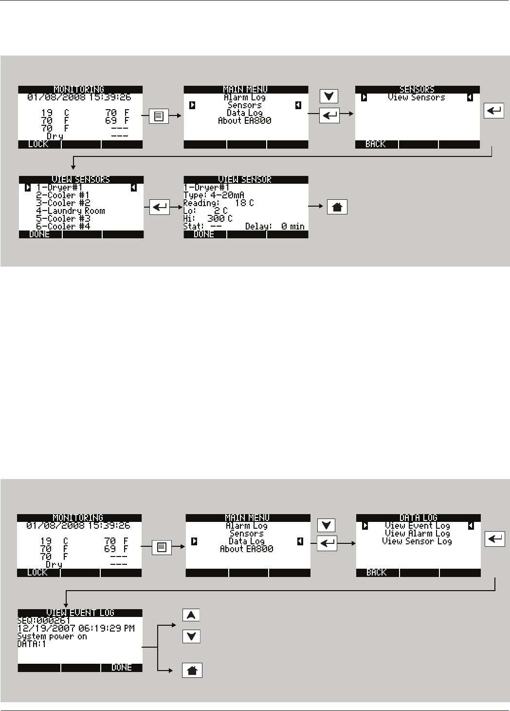
52 D-011-0152
Viewing Limit Settings
Viewing Limit Settings
To view the current readings and the limits of a sensor that is not in an alarm state perform the following procedure:
Viewing the Event Log
The EA800 Alarm System logs up to 100 events in its Event Log. At the minimum, the following events are logged:
■System power on: the date and time when the EA800 was powered on.
■Sensor added: indicates that a sensor was added.
■Sensor deleted: indicates that a sensor was deleted.
■WRM Msg error: indicates that an error message was generated.
■Firmware updated: indicates that the firmware was upgraded.
■Alarm log cleared: indicates when the alarm log was cleared.
■Data log cleared: indicates when the data log was cleared.
Note: Pressing either arrow key will eventually wrap to sequence number 1.
To review the event log, perform the following procedure:
To return to Active Alarm
or Monitoring screen.
OR
Press arrow keys to scroll up or down
through the logged events.
To return to Active Alarm
or Monitoring screen.
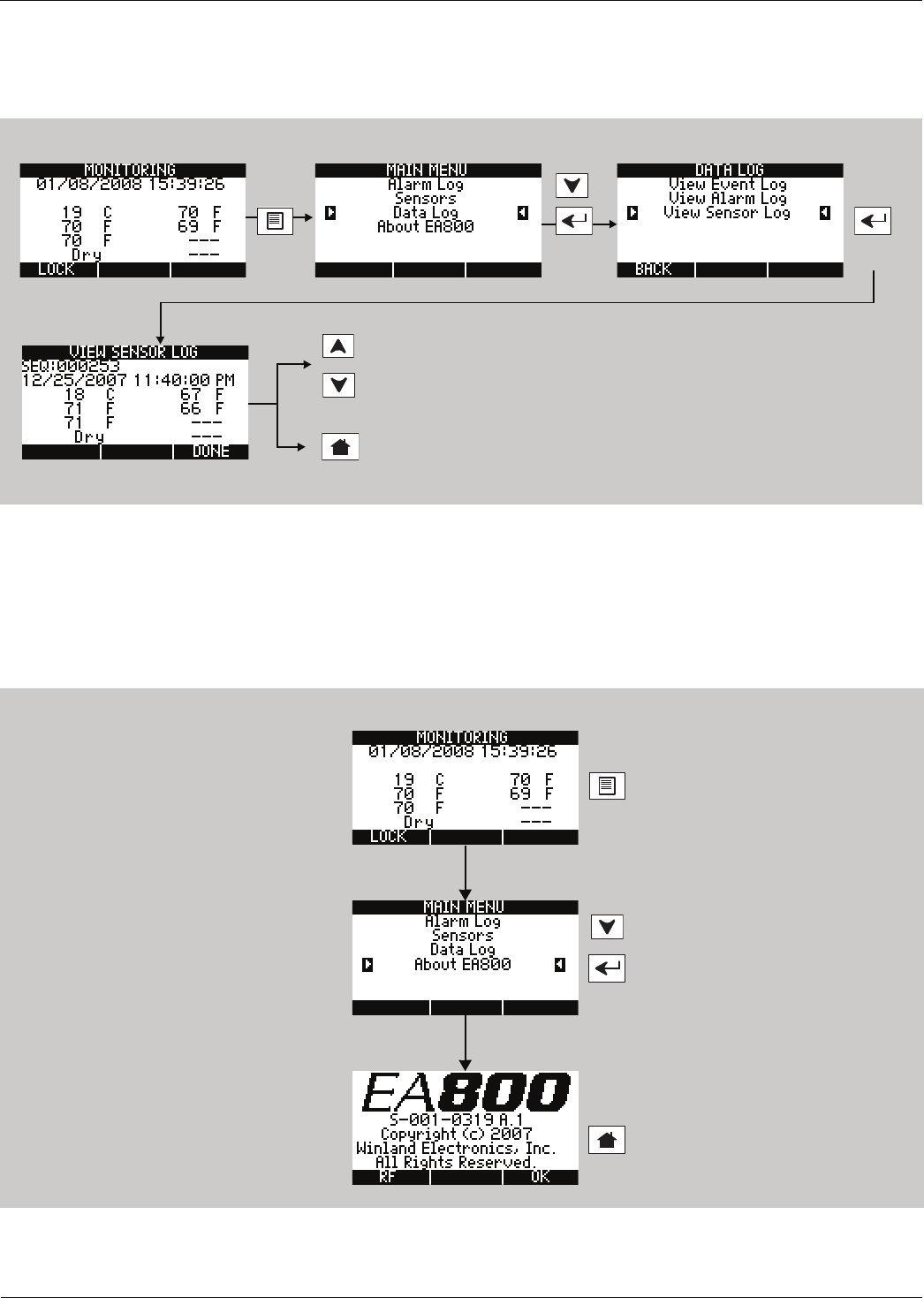
Operation
D
-
011
-
0152
53
Viewing the Sensor Log
The sensor log provides a history of the environmental conditions for all installed sensors at a glance. Up to
100 data sets are stored in the sensor log. To view the sensor log, perform the following procedure:
Viewing Firmware Information
The About EA800 menu item displays the currently running firmware version. To view the firmware version, do the
following:
Note: The firmware revision number shown indicates the firmware version currently installed.
To return to Active Alarm
or Monitoring screen.
Press arrow keys to scroll up or down
through the logged data.
OR
To return to Active Alarm
or Monitoring screen.
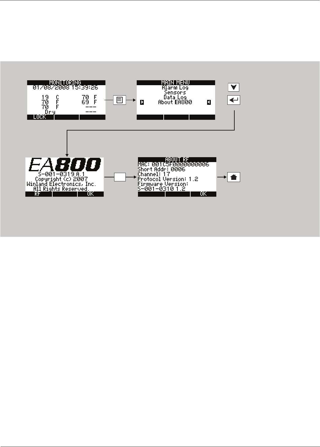
54 D-011-0152
Viewing RF Information
Viewing RF Information
The ABOUT RF screen displays the EA800 base unit’s MAC address, the RF channel currently in use, the RF
communications protocol version, and the RF subsystem’s firmware version. To view the RF settings, perform the
following procedure:
Note: The firmware revision number shown indicates the firmware version currently installed.
Displays the Active Alarm
or Monitoring screen.
F1
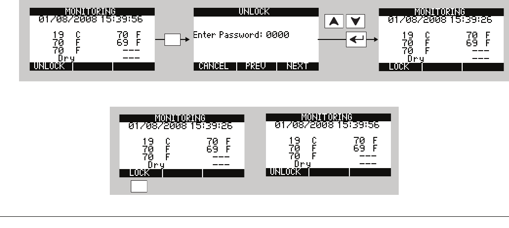
D
-
011
-
0152
55
Maintenance
This chapter contains instructions on performing the following maintenance tasks:
■Lock/unlock the base unit: See “Locking and Unlocking the EA800” on page 55
■Pausing/resuming sensor monitoring: See “Pausing Monitoring and Cancelling Pause” on page 56
■Adding sensors: See “Adding a Sensor” on page 57
■Replacing a sensor. See “Replacing a Sensor” on page 57
■Deleting a sensor. See “Deleting a Sensor” on page 59
■Reprogramming a Relay. See “Reprogramming a Relay” on page 59
■Exporting all logs. See “Exporting the Stored Logs” on page 68
■Clear the alarm log. See “Clearing the Alarm Log” on page 64
■Clear the sensor log. See “Clearing the Sensor Log” on page 64
■Change the current date or time. See “Changing the Date or Time Setting” on page 61
■Change date format. See “Changing the Date Format” on page 60
■Change time format. See “Changing the Time Format” on page 60
■Change data collection frequency. See “Changing Sensor Data Collection Frequency” on page 61
■Enabling or disabling the audible alarm buzzer. See “Changing the Buzzer Setting” on page 62
■Changing the password. See “Changing the Password” on page 63
■Clearing the alarm log file. See “Clearing the Alarm Log” on page 64
■Clearing the sensor log file. See “Clearing the Sensor Log” on page 64
■Updating the firmware. See “Updating the Firmware” on page 65
■Saving the configuration to a USB drive. See “Saving Configuration Settings” on page 66
■Loading a configuration from a USB drive. See “Loading Configuration Settings” on page 67
■Exporting stored logfiles for review or archiving. See “Exporting the Stored Logs” on page 68
Note: The base unit must be unlocked before you can perform any of the maintenance tasks in this chapter.
Locking and Unlocking the EA800
The base unit is normally locked. When locked, it cannot be programmed and certain maintenance features, such
as PERFORMANCE, cannot be accessed. Locking restricts access to these features to authorized personnel only. If
left unlocked, the base unit locks automatically after a period of inactivity.
The current state of the EA800 is indicated by the text above the F1 soft key when the home screen is displayed:
■When UNLOCK is displayed, the base unit is locked. Press F1, use the PREV and NEXT soft keys to advance
the cursor to the next digit, and use the arrow keys to enter the value for the password. The default password
is 0800.
■When LOCK is displayed: The base unit is currently unlocked. Press F1 to lock it. The base unit locks
automatically after 30 minutes of inactivity
Enter:
0800
F1
F1
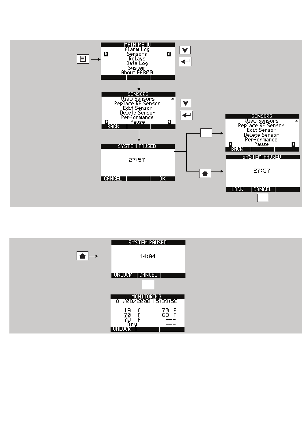
56 D-011-0152
Pausing Monitoring and Cancelling Pause
Pausing Monitoring and Cancelling Pause
To prevent false alarms when performing maintenance, pause sensor monitoring. Pausing stops monitoring and
ignores active alarms for a 30-minute period. When the pause function times out, monitoring automatically starts.
To pause the EA800 perform the following procedure:
When the system is paused the SYSTEM PAUSED screen is displayed until pause times out (30 minutes) or you
cancel it. You can access all functions in the main menu while the system is paused. To resume monitoring instead
of allowing the pause function to time out perform the following procedure:
F2
Unlock as shown in “Locking
and Unlocking the EA800”
on page 55
F3
OR
To cancel pause and
resume monitoring
F2
Unlock as shown in “Locking
and Unlocking the EA800”
on page 55
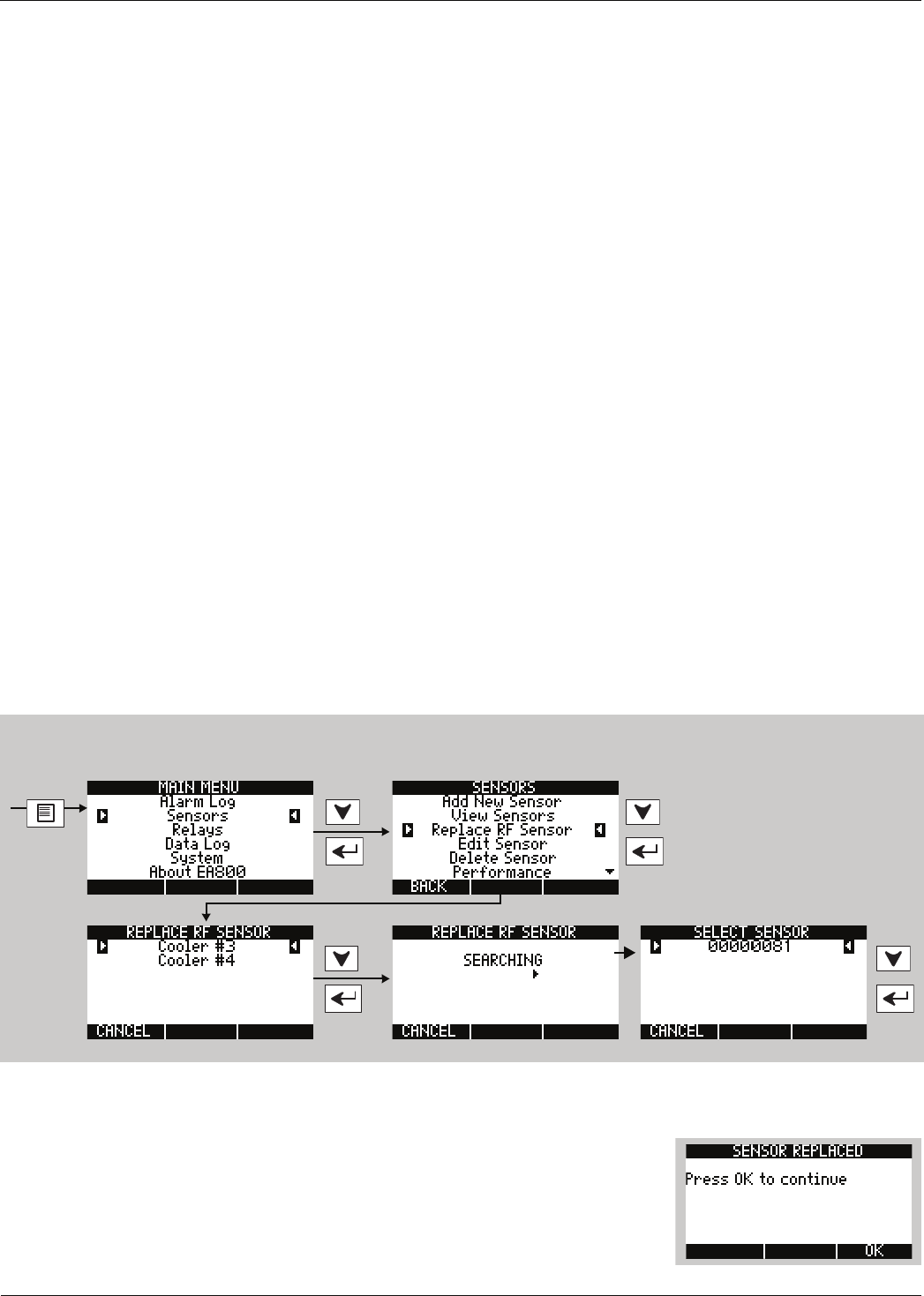
Maintenance
D
-
011
-
0152
57
Adding a Sensor
The procedure for adding a sensor to an existing system is the same as for a new system. See “Install the Wired
Sensors” on page 22 or “Install the Wireless Sensors” on page 22 for instructions on physically installing the sensor
and then programming the sensor in the EA800 base unit.
Note: See “Pausing Monitoring and Cancelling Pause” on page 56 and pause the base unit before you begin
so you can set up the sensor without tripping the alarm.
Note: If adding more than one sensor, add them to the system one at a time. (Power on one sensor and add it
to the system, then power on the next sensor and add it). Do not power on all sensors at the same time.
Note: Update the system’s Configuration Worksheets to document any changes.
Replacing a Sensor
The EA800 allows you to replace an existing, programmed wireless sensor with another of the same type. When
replaced, the original sensor’s programmed settings and parameters are retained and applied to the new sensor. If
you need to change settings other than those provided in the Edit Sensor screen, you must delete the existing
sensor and then add the replacement sensor.
Note: See “Pausing Monitoring and Cancelling Pause” on page 56 to pause the base unit before you begin so
you can replace the sensor without tripping the alarm.
Note: If adding more than one sensor, add them to the system one at a time. (Power on one sensor and add it
to the system, then power on the next sensor and add it). Do not power on all sensors at the same time.
Note: Update the system’s Configuration Worksheets to document any changes.
To replace an existing wireless sensor:
1. Physically replace the sensor with another of the same type and ensure it is powered on.
2. Perform the procedure shown below to allow the base unit to search for the new sensor:
3. Select the detected sensor from the SELECT SENSOR screen. If the detected new sensor is the same type as the
replaced sensor, the SENSOR REPLACED screen is displayed.
4. Press OK (F3) to return to the SENSORS screen. If the replacement sensor
appears in the list, highlight it and press Accept. If it does not appear in the list,
press Cancel (F1) to continue the search process.
Unlock the EA800 as shown
in “Locking and Unlocking
the EA800” on page 55
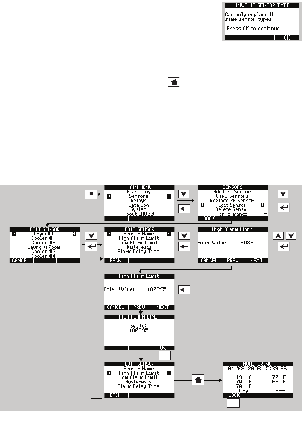
58 D-011-0152
Editing Sensor Parameters
5. If the detected new sensor is not the same type as the replaced sensor, the
INVALID SENSOR TYPE screen is displayed. Press OK (F3) to return to the
SENSORS screen:
6. Do one of the following:
•Replace the physical sensor with one that matches the type of the
replaced sensor and repeat this procedure.
•Delete the sensor from the base unit and replace with the new sensor (of a different type). See “Deleting
a Sensor” on page 59 and “Adding a Sensor” on page 57.
7. If you wish to replace another wireless sensor, repeat this procedure.
8. If you are finished performing sensor maintenance, press to exit maintenance and resume monitoring.
9. Press F1 to lock the keypad.
Editing Sensor Parameters
The general procedure for editing sensor parameters is provided below. Not all sensor parameters can be edited
for an installed sensor. The editable parameters are dependent on the installed sensor, so the EDIT SENSOR screen
varies according to the sensor selected. You cannot edit the following:
■The low and high scaled values for a 4-20mA sensor. If these require changes, you must delete the 4-20mA
sensor and re-add it to the system. See “Connecting Wired HA-III+ Humidity Sensors” on page 25.
■A sensor’s type. For example, if a 4-20mA sensor was incorrectly added as a Blue temperature sensor, you
must delete the incorrect sensor and then re-add the correct sensor.
■
The unit of measure. If unit of measure must be changed, the sensor must be deleted and re-added to the system.
Note: Update the system’s Configuration Worksheets to document changes.
F3
F1
Unlock the EA800 as
shown in “Locking and
Unlocking the EA800” on
page 55
Select the sensor to edit. Select the parameter to be edited.
Use PREV, NEXT, and arrow keys to change value
as required.
To edit another
parameter
when done
editing
to lock
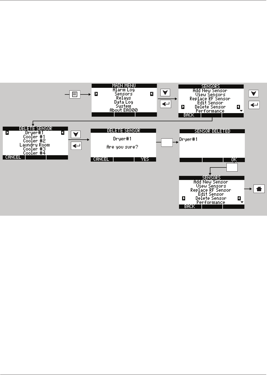
Maintenance
D
-
011
-
0152
59
Reprogramming a Relay
Note: Ensure that the system’s Configuration Worksheets are updated to document any changes.
A Relay can be reprogrammed as desired at any time. Perform the procedure outlined in “Configuring the Relays”
on page 48 to reprogram any relay in the system.
Deleting a Sensor
Note: Update the system’s Configuration Worksheets to document any changes.
To delete a sensor perform the following procedure:
F3
Unlock the EA800 as shown
in “Locking and Unlocking
the EA800” on page 55
F3
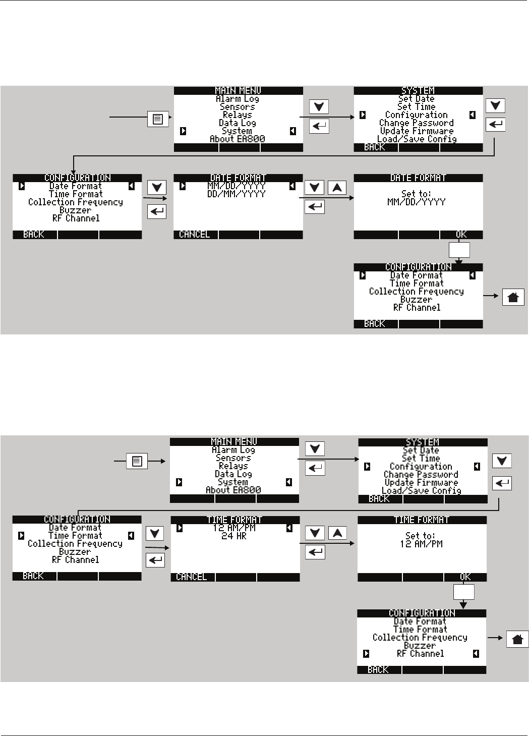
60 D-011-0152
Changing the Date Format
Changing the Date Format
Note: Update the system’s Configuration Worksheets to document any changes.
Note: The default date format is MM/DD/YYYY.
To change the date format perform the following procedure:
Changing the Time Format
Note: Update the system’s Configuration Worksheets to document any changes.
Note: The default time format is 24 HR.
To change the time format perform the following procedure:
F3
Unlock the EA800 as shown
in “Locking and Unlocking
the EA800” on page 55
F3
Unlock the EA800 as shown
in “Locking and Unlocking
the EA800” on page 55
F3
Unlock the EA800 as shown
in “Locking and Unlocking
the EA800” on page 55
F3
Unlock the EA800 as shown
in “Locking and Unlocking
the EA800” on page 55
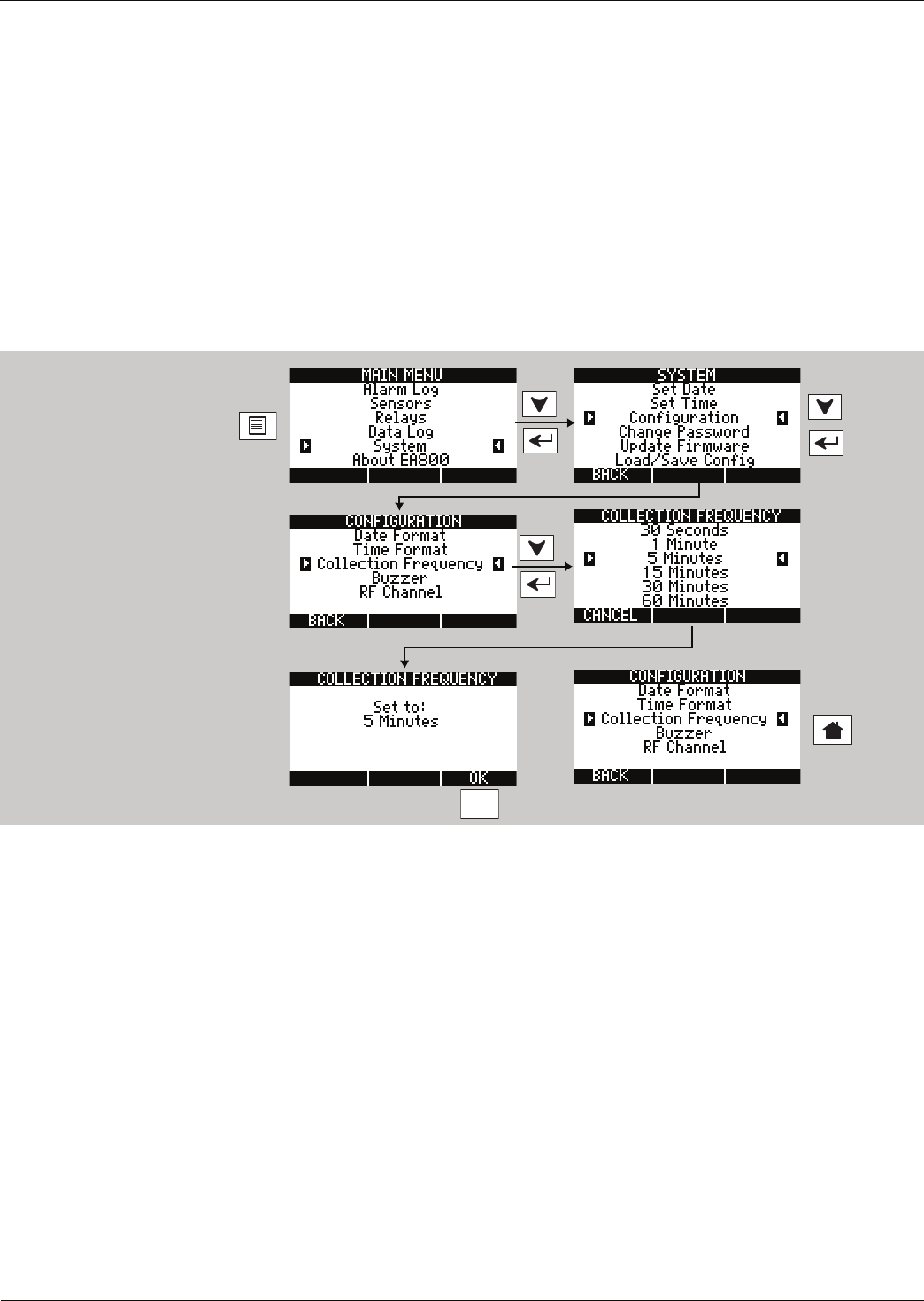
Maintenance
D
-
011
-
0152
61
Changing the Date or Time Setting
To change the date see “Setting the Current Date” on page 31.
If your region uses Daylight Savings Time and you want the EA800 to display the correct time, you must change
the time setting manually when Daylight Savings Time starts and ends. See “Setting the Time” on page 32.
Changing Sensor Data Collection Frequency
Note: Update the system’s Configuration Worksheets to document any changes.
Note: The default collection frequency is 5 Minutes. See Table 4 on page 9 for information on correlating data
collection frequency to the number of data points collected.
To set the data collection frequency perform the following procedure:
F3
Unlock the EA800 as shown
in “Locking and Unlocking
the EA800” on page 55

62 D-011-0152
Changing the Buzzer Setting
Changing the Buzzer Setting
Note: Update the system’s Configuration Worksheets to document any changes.
Note: The default buzzer configuration is ENABLED and the active condition of the on-board buzzer mirrors what
is assigned to the Auxiliary Relay.
To change the buzzer setting perform the following procedure:
WARNING
!
Changing the buzzer setting to DISABLED turns off the audible alarm tone from
the base unit. Do not disable the buzzer unless you are sure you do not want the
base unit to emit an audible tone when an alarm occurs. The active condition of
the buzzer mirrors what is assigned to the auxiliary relay.
Unlock the EA800 as shown
in “Locking and Unlocking
the EA800” on page 55
F3
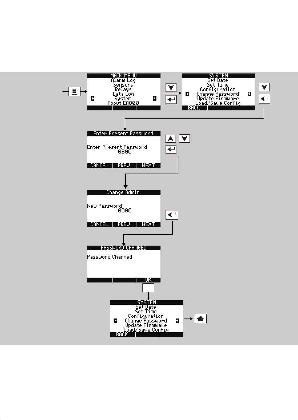
Maintenance
D
-
011
-
0152
63
Changing the Password
Note: Update the system’s Configuration Worksheets to document any changes.
Note: If you do not enter a valid password you will not be allowed to change the selected password. The default
password (0800) cannot be changed or deleted. One user-configurable password may be set in addition
to the default 0800 password.
To set or change the user-configurable password perform the following procedure:
F3
Unlock the EA800 as shown
in “Locking and Unlocking
the EA800” on page 55
Use NEXT key to advance the
cursor to the next digit, then use the
arrow keys to set the value.
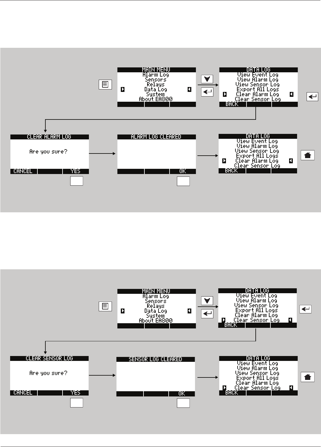
64 D-011-0152
Clearing the Alarm Log
Clearing the Alarm Log
To clear all stored alarm records perform the following procedure:
Note: You cannot clear the Event Log.
Clearing the Sensor Log
To clear all stored sensor records perform the following procedure:
Note: You cannot clear the Event Log.
F3
Unlock the EA800 as shown in
“Locking and Unlocking the EA800”
on page 55
F3
F3
Unlock the EA800 as shown in
“Locking and Unlocking the EA800”
on page 55
F3
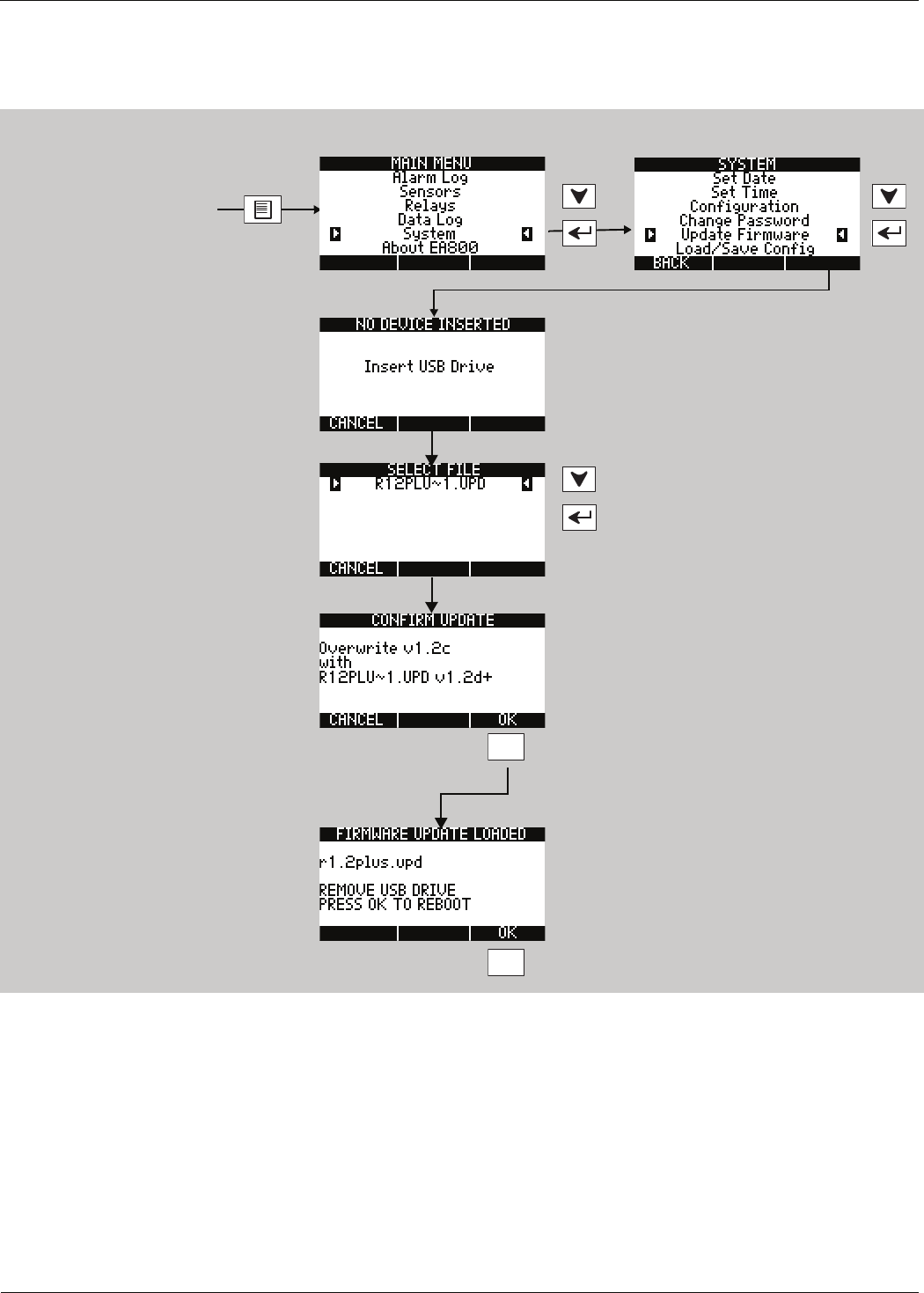
Maintenance
D
-
011
-
0152
65
Updating the Firmware
Download the latest firmware from www.winland.com to your computer, then save it to a USB jump drive before
performing the procedure for updating the firmware as shown below.
F3
Unlock as shown in “Locking
and Unlocking the EA800”
on page 55
During the process, the UPDATING
FLASH screen is displayed.
F3
The EA800 reboots with the new firmware.
If this message appears,
insert the USB drive with
new firmware into the USB
port.
Remove USB drive when
update is complete.
Note: The file name is limited to 15
characters or less (not includ-
ing the file extension “.UPD”).
File names greater than 15
characters are not supported
and will not be displayed on the
EA800.
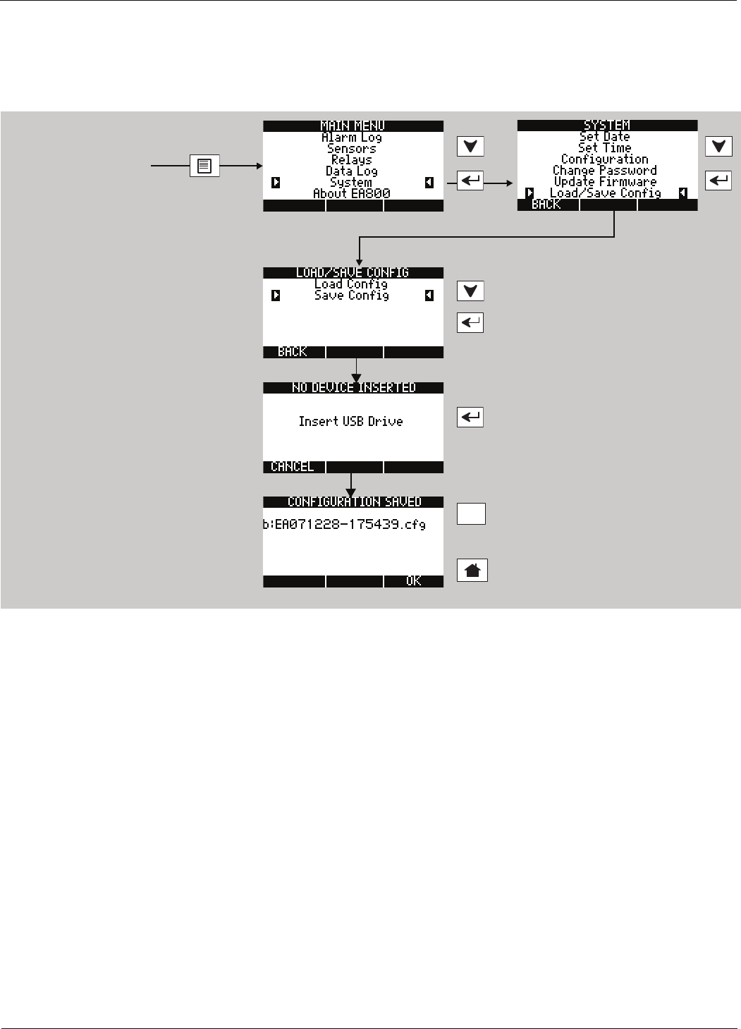
66 D-011-0152
Saving Configuration Settings
Saving Configuration Settings
You can export the configuration settings from the EA800 to serve as an archive for the system or as a template for
quickly programming other systems. The configuration data is stored in a machine-readable format. To export
configuration to a USB drive perform the following procedure:
Now that the configuration is stored on the USB drive you should copy it onto a PC to provide a backup in the event
that the USB drive is lost or fails. By default, the configuration file is named EAYYMMDD-HHMMSS.cfg where:
■EA indicates that the configuration file is from the EA800.
■YYMMDD is the current date.
■HHMMSS is the current time in 24 hour format.
It is suggested that you rename saved configuration files to identify the specific EA800 system they came from
using up to 15 characters, not including the file extension ‘CFG’. File names longer than 15 characters are not
supported.
Unlock as shown in “Locking
and Unlocking the EA800”
on page 55
If this message appears,
insert the USB drive with
the configuration into the
USB port.
F3
To return to
LOAD/SAVE CONFIG screen
To return to the home
screen.
Remove USB drive when
export is complete.

Maintenance
D
-
011
-
0152
67
Loading Configuration Settings
You can load configuration settings from a previously installed EA800 to serve as the template for the system being
installed or updated. To load a configuration from a USB drive, insert the USB drive into the USB port and perform
the following procedure:
Unlock the EA800 as shown
in “Locking and Unlocking
the EA800” on page 55.
This message appears only
if no USB drive is present.
F3
To return to LOAD/SAVE
CONFIG screen
To return to the home
screen.
Select the configuration
file to download.
Remove USB drive when
import is complete. OR
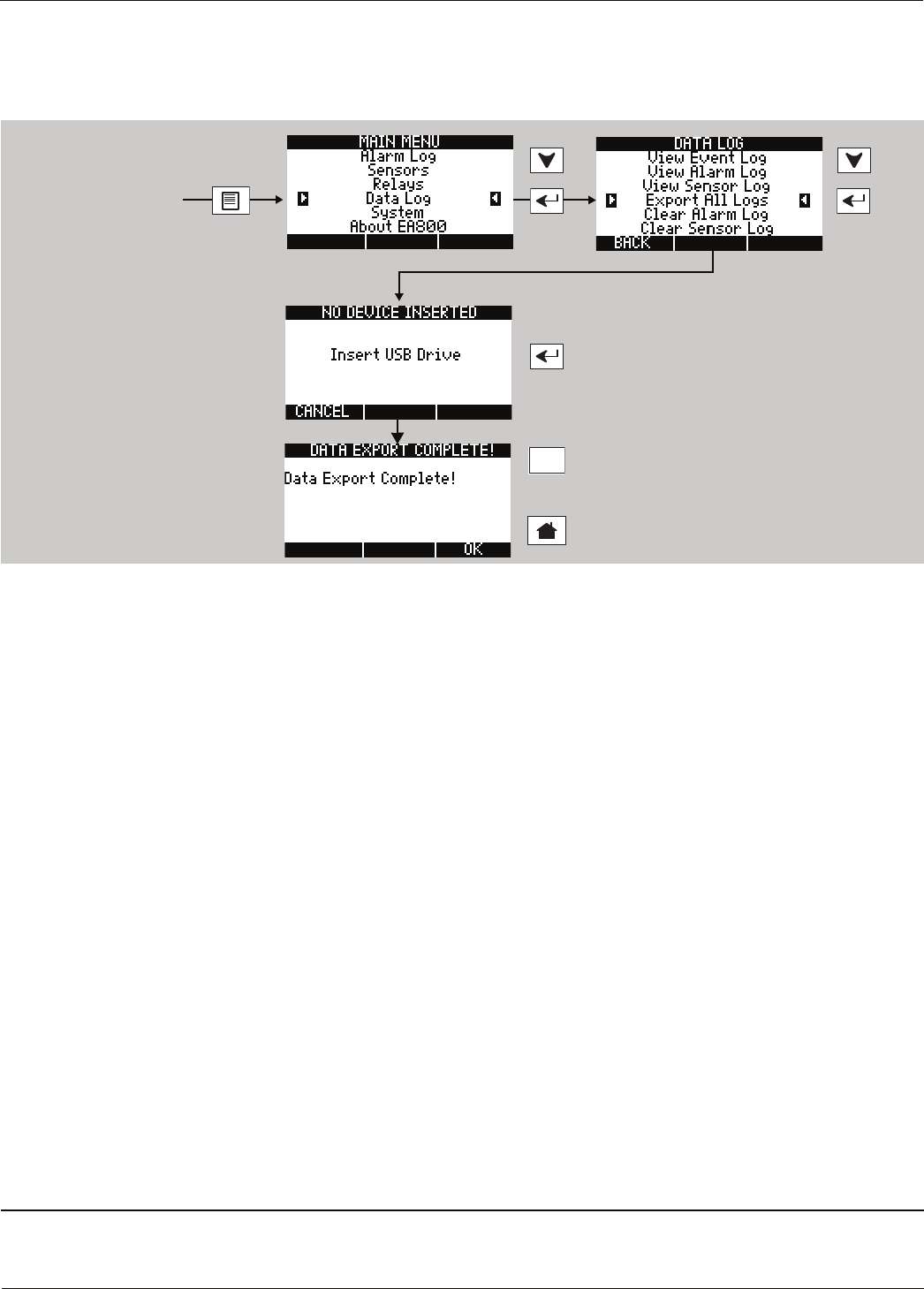
68 D-011-0152
Exporting the Stored Logs
Exporting the Stored Logs
You can export the logs stored in the EA800 for archiving or later review. The export procedure exports the alarm
log, data log, and event log files. To export the logfiles perform the following procedure:
The EA800 stores the log files on the USB drive in comma separated value (CSV) format. The files are named in
the format XYYMMDD-HHMMSS.txt where:
■X = A, E, or D:
•A = Alarm log file
•E = Event log file
•D = Sensor data log file
■YYMMDD is the current date.
■HHMMSS is the current time in 24 hour format.
You can rename the files to more easily identify the EA800 system they came from, however, the first character
designating the log type (A, E, or D) must be retained if using the template available at www.winland.com. Because
the files are in CSV format they can be converted to tables in a word processing program or imported into a
spreadsheet program.
Exported Alarm Data
The following is an example of exported alarm data:
12/27/2007 01:28:39 ,3,Laundry Room,Wet,Dry,Dry,,Wired,WaterBug,1
12/27/2007 01:29:10 ,3,Laundry Room,Dry,Dry,Dry,,Wired,WaterBug,0
12/27/2007 02:38:45 ,4,Cooler #3,67,-58,158,F,RF Contact,Blue,4
12/27/2007 02:39:48 ,4,Cooler #3,67,-58,158,F,RF Contact,Blue,0
12/27/2007 07:10:45 ,3,Laundry Room,Wet,Dry,Dry,,Wired,WaterBug,1
12/27/2007 07:10:50 ,3,Laundry Room,Dry,Dry,Dry,,Wired,WaterBug,0
The data presented provides the following alarm information:
Date and time
of reading
Sensor
Number
Sensor
Name
Sensor
Reading
(at time of
alarm)
Low
Limit
Value
High
Limit
Value
Unit of
Measure
Sensor
Connection
Sensor
Type Code
12/27/2007
01:28:39 3Laundry
Room Wet Dry Dry N/A Wired WaterBug 1
F3
To return to SELECT SENSOR screen
To return to home screen.
OR
Unlock as shown in “Locking
and Unlocking the EA800”
on page 55
Appears only if a USB
drive is not installed
The screen displays
the progress of the
data export. Remove
USB drive when
export is complete.

Maintenance
D
-
011
-
0152
69
Exported Event Data
The following is an example of exported event data:
12/24/2007 07:06:03 PM,Sensor deleted,1
12/24/2007 07:10:50 PM,Sensor added,1
12/25/2007 02:27:14 PM,System power on,1
12/25/2007 02:27:50 PM,Sensor deleted,1
12/25/2007 02:36:02 PM,Sensor added,1
12/25/2007 03:08:55 PM,Sensor deleted,1
12/25/2007 03:11:19 PM,Sensor added,1
The data presented provides the following event information:
Exported Sensor Data
The following is an example of exported sensor data. The data is collected from all sensors at the intervals as
specified in the Data Collection system setting (every 5 minutes in this example). Each sensor is allocated 11 data
fields and 11 data fields are provided for all 8 sensors, regardless of how many sensors are actually connected.
12/26/2007 09:55:00
PM,17,C,,0,0,0,0,0,0,0,0,69,F,,0,0,0,0,0,0,0,0,69,F,,0,0,0,0,0,0,0,0,1,,,0,0,0,0,0,0,0,0,66,F,255,0,0
,0,0,0,0,0,0,65,F,105,0,0,0,0,0,0,0,0,,,,0,1,0,0,0,0,0,0,,,,0,1,0,0,0,0,0,0
12/26/2007 10:00:01
PM,17,C,,0,0,0,0,0,0,0,0,69,F,,0,0,0,0,0,0,0,0,69,F,,0,0,0,0,0,0,0,0,1,,,0,0,0,0,0,0,0,0,66,F,255,0,0
,0,0,0,0,0,0,65,F,90,0,0,0,0,0,0,0,0,,,,0,1,0,0,0,0,0,0,,,,0,1,0,0,0,0,0,0
12/26/2007 10:05:00
PM,17,C,,0,0,0,0,0,0,0,0,69,F,,0,0,0,0,0,0,0,0,69,F,,0,0,0,0,0,0,0,0,1,,,0,0,0,0,0,0,0,0,66,F,255,0,0
,0,0,0,0,0,0,65,F,75,0,0,0,0,0,0,0,0,,,,0,1,0,0,0,0,0,0,,,,0,1,0,0,0,0,0,0
12/26/2007 10:10:00
PM,17,C,,0,0,0,0,0,0,0,0,69,F,,0,0,0,0,0,0,0,0,69,F,,0,0,0,0,0,0,0,0,1,,,0,0,0,0,0,0,0,0,66,F,240,0,0
,0,0,0,0,0,0,65,F,75,0,0,0,0,0,0,0,0,,,,0,1,0,0,0,0,0,0,,,,0,1,0,0,0,0,0,0
12/26/2007 10:15:00
PM,17,C,,0,0,0,0,0,0,0,0,69,F,,0,0,0,0,0,0,0,0,69,F,,0,0,0,0,0,0,0,0,1,,,0,0,0,0,0,0,0,0,66,F,255,0,0
,0,0,0,0,0,0,65,F,65,0,0,0,0,0,0,0,0,,,,0,1,0,0,0,0,0,0,,,,0,1,0,0,0,0,0,0
12/26/2007 10:20:01
PM,17,C,,0,0,0,0,0,0,0,0,69,F,,0,0,0,0,0,0,0,0,69,F,,0,0,0,0,0,0,0,0,1,,,0,0,0,0,0,0,0,0,66,F,255,0,0
,0,0,0,0,0,0,65,F,75,0,0,0,0,0,0,0,0,,,,0,1,0,0,0,0,0,0,,,,0,1,0,0,0,0,0,0
Each entry is interpreted as:
12/26/2007 09:55:00 PM,(11 CSVs for Sensor 1),(11 CSVs for Sensor 2),(11 CSVs for Sensor 3),(11 CSVs for
Sensor 4),(11 CSVs for Sensor 5),(11 CSVs for Sensor 6),(11 CSVs for Sensor 7),(11 CSVs for Sensor 8)
There is a line feed and a carriage return character at the end of each The data collected at 09:55:00 in the data
log example above provides the sensor information shown below for Sensor 1. The data represented by each of
the 11 data fields is defined below and is applicable to each of the 8 sensors that may be connected.
■Blank (,,): The data is null and is not valid for that sensor. For example, the LQI (signal strength) position is null
for wired sensors but shows the LQI value as shown for the two wireless sensors (255 and 105 respectively).
Where wireless sensors are not installed the LQI is also blank indicating that no reading is made.
■0 (,0,): The data is valid and is valid data for that sensor’s data point.
Date and time of event Event description Code (For Factory Use)
12/24/2007 07:06:03 PM Sensor deleted 1
Date and time of
reading
Sensor # 1
CSV1
Reading
CSV2
Unit of
Measure
CSV3
LQI
CSV4
Pause
CSV5
Pending
Alarms
CSV6
Low
CSV7
High
CSV8
Comm
CSV9
Fail
CSV10
No Data
CSV11
Low
Battery
12/26/2007
09:55:00 PM 17 C Null 0 0 0 0 0 0 0 0

70 D-011-0152
Exporting the Stored Logs

D
-
011
-
0152
71
Troubleshooting
Operating or setup errors are indicated by flashing data on the display. Often, a programming error also results in
an alarm for the misprogrammed relay. The table below shows and describes common error displays, along with
corrective action. For updated information, go to the EA800 page at www.winland.com and look for the
troubleshooting section.
Table 13 Troubleshooting
Symptom Cause Corrective Action
Temperature reading indi-
cates maximum when
temperature is actually
less.
Wired sensor is shorted
Wired sensor cable has a short.
Sensor has failed
Ensure that the sensor connection is not shorted.
A short equals zero resistance and thus the max-
imum value.
Replace damaged cable.
Contact Winland Technical Services at
1-800-635-4269
Temperature reading indi-
cates minimum when tem-
perature is actually
greater.
Wired sensor is not connected
Wired sensor cable has an open.
Sensor has failed
Ensure that the sensor is connected to the cor-
rect header pins. An open connection equals an
infinite resistance and thus the minimum value.
Replace damaged cable.
Contact Winland Technical Services at
1-800-635-4269.
Temperature display does
not equal actual tempera-
ture.
Incorrect sensor programmed Verify the actual sensor connected to the sensor
input is programmed appropriately. Each temper-
ature sensor is limited to a specific operating
range.
Display flashes repeat-
edly between the Winland
Electronics Inc. screen
and a blank screen.
The EA800 reboots repeatedly
and fails to successfully com-
plete the boot process.
Cycle power to the EA800 and wait for a period
of time before reapplying power.
If a USB drive is attached to the USB port,
remove it and cycle power as noted above.
If the problem recurs, contact Winland Technical
Service at 1-800-635-4269.
The display flashes while
displaying the
ACTIVE ALARMS screen
A sensor's reading has
exceeded a set limit.
A wireless sensor is not commu-
nicating with the base unit.
Verify the environmental conditions of the sen-
sor.
Verify the received signal strength as outlined in
“Verifying RF Signal Strength” on page 72.
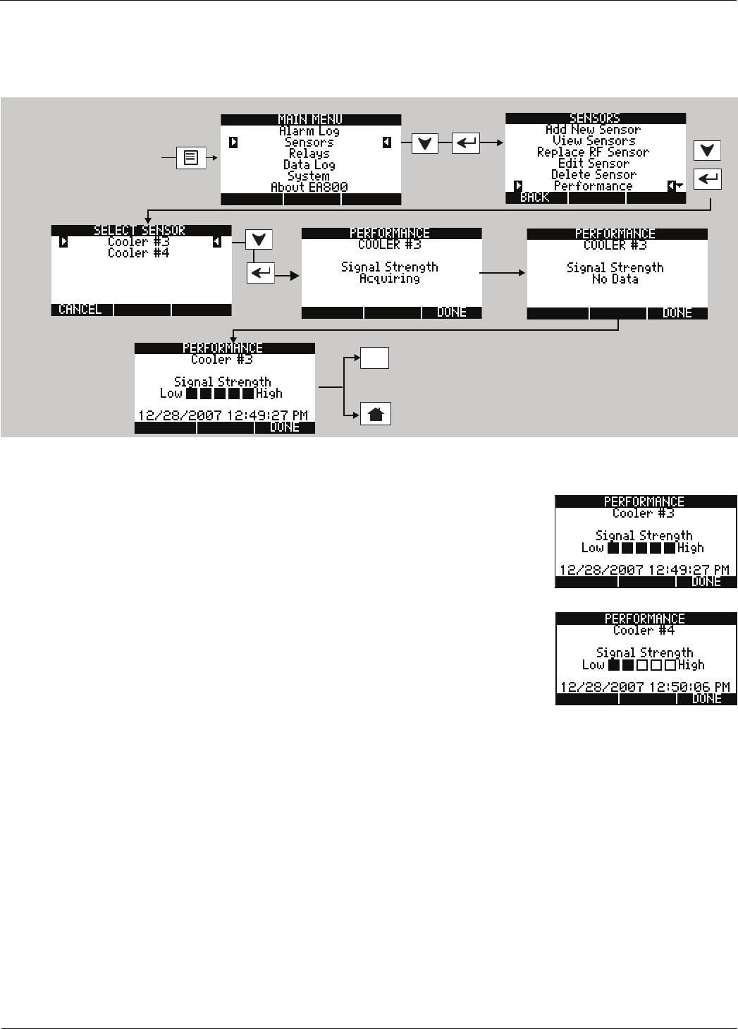
72 D-011-0152
Verifying RF Signal Strength
Verifying RF Signal Strength
Viewing Signal Strength for a Wireless Sensor
To verify the RF signal strength received by the EA800 perform the following procedure:
If the remote sensor transmitter you are verifying is battery powered, it may take up to 30 seconds for the base unit
to receive a transmission from the remote sensor.
The base unit displays an approximation of signal strength as indicated by the
number of filled boxes on the screen as shown at right.
Note: The date and time shown at the bottom of the PERFORMANCE screen is the
time stamp of the last received transmission.
Ensure that at least 2 Signal Strength bars are displayed as shown at right. If not, it is
recommended that the sensor be relocated until at least 2 bars are achieved. More
bars reduces sensor alarm latency, reduces the probability of communication
alarms, and increases battery life.
For additional information on how to improve signal strength, refer to Winland
application note AN00101.
F3
Unlock the EA800 as shown
in “Locking and Unlocking
the EA800” on page 55
To return to SELECT
SENSOR screen
To return to home screen.

D-011-0152 73
Specifications
Base Unit and Sensor Specifications
The following table lists the specifications for the EA800 base unit, sensors, and accessories.
Table 14 Specifications
Item Specification
Dimensions Approximately 230 mm x 199 mm x 55 mm(“9.375 H x 8.125" W x 2.25" D)
Weight Base Unit: 0.27 kg (0.6 lb.)
Wireless Sensors: 0.11 kg (0.26 lb.) with batteries
Mounting
The EA800 base unit is mountable directly to 3-gang standard electrical enclo-
sure using pre-drilled holes on the EA800 rear case.
The EA800 base unit and wireless sensors can be mounted to drywall or simi-
lar surfaces using the appropriate anchors (not included).
Case Material ABS, UL94V-0 rated
EA800 Input (Operating) Volt-
age 1, 2, 3
+11 to +26VDC @ ≤500mA current draw. Standard commercial filtered and
regulated power supply suitable. Supplied by AC adapter (not included; see
Accessories) or alarm panel.
Note: Power supply requirement does not include additional require-
ments for loads switched through alarm output relays where
power is derived from EA800 EA400 terminal strip connections.
EA800 Aux Power Out Equivalent to DC input voltage used: +11 to +26VDC
(Maximum output current 0.5A).
EA800 Real-Time Clock Battery CR2032 (3V Cell)
Wireless Sensor Input Voltage
Either:
•+12VDC @ <
100mA current draw using a 2.1 mm barrel plug, center
positive; OR
• 2xAA Alkaline Batteries (1.5V Cell)
Wireless Sensor Radiating
Power (minimum, at PCB
antenna connector)
• EA800 base unit: -3.5 dBm
• Sensors: -2.5 dBm
Wireless Sensitivity:
(minimum at printed circuit
board antenna connection)
• EA800: -94.5 dBm
• Sensors: -95.5 dBm
Low and High Limit Adjust Range:
(Winland thermistor sensors only)
Temperature: -80° C to 150° C
(-112° F to 302° F)
Note: The Low and High Limit Adjust Range is dependent upon the
sensor being used. See “Accessories” on page 44.
Humidity: 5 to 95% RH
Note: The Low and High Limit Adjust Range is dependent upon the
sensor being used. See “Accessories” on page 44.
Water Presence: No Alarm / Alarm
Sensors Up to four wired sensors
Up to four wireless sensors
Cable Length to Wireless
Multi-Function Sensor
EA-WMFS 100 ft. maximum
Wired Temperature Sensor: 2-wire; maximum 304 m (1000 ft.) cabling length
Wired Humidity Sensor: 3-wire; maximum 304 m (1000 ft.) cabling length

74 D-011-0152
Accessories
Accessories
Accessories available for use with the EA800 Environmental Alarm System are listed below.
Wired Water Presence Sensor: 2-wire; maximum 304 m (1000 ft.) cabling length
Wired 4-20mA Sensor EA800 load (160 Ohms maximum)
Relay Outputs
(9) Form C with 3-terminal NC/COM/NO connections.
Note: There are 8 primary relays (1 dedicated for each sensor) and
1 auxiliary relay.
Relay Contact Ratings Max 30VDC @ 1 amp resistive.
Not for use with AC power.
Relay Logic Each relay is user configurable.
Display 128x64 graphic LCD, with blue backlight
Device Environmental Operating Range:
Humidity: 5 to 95% RH, non-condensing
Temperature, Operating: 0°C to 50°C (32° F to 122° F). Not for installation inside coolers or freezers.
Ambient Environmental Quality: Indoor use intended, non-corrosive environment
Conformity Certifications
FCC Part 15, Subpart C, Class B
ICES-003, Issue 3; 1997
NRTL CUE certification mark
Warranty Two (2) Year Limited Warranty. See Warranty and Service Information.
Notes:
1. Where required, this equipment is to be isolated from the mains supply by a limited power source as specified
in EN60950.
2. All terminals must be connected to a Class 2 Power Limited Circuit complying with the National Electric Code
NFPA 70, Article 725.
3. See “Specifications” on page 46 for power supply requirements.
Table 15 Accessories
Item (Winland Part Number) Description
BZ-3: Audible alarm module
(PN 1183) Buzzer for connection to auxiliary relay output that provides audible alarm
indication.
Power supply (transformer)
(PN L-020-0085)
Regulated 110 VAC-to-12 VDC @ >500 mA (minimum) transformer suitable for
use with EA800.
Note: Power supply must be a limited power source per notes 1 and 2 in
Table 14.
Table 14 Specifications — continued
Item Specification

Appendix A: Screen Maps
D
-
011
-
0152
75
Appendix A: Screen Maps
The figures in this Appendix illustrate the flow of all EA800 screens.
Figure 17. Locked Screen Map
The displayed screen is dependent on whether an alarm is active or not.
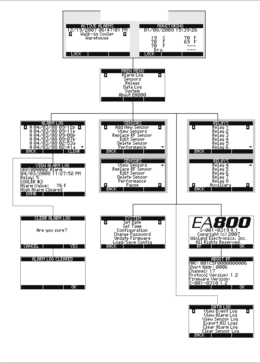
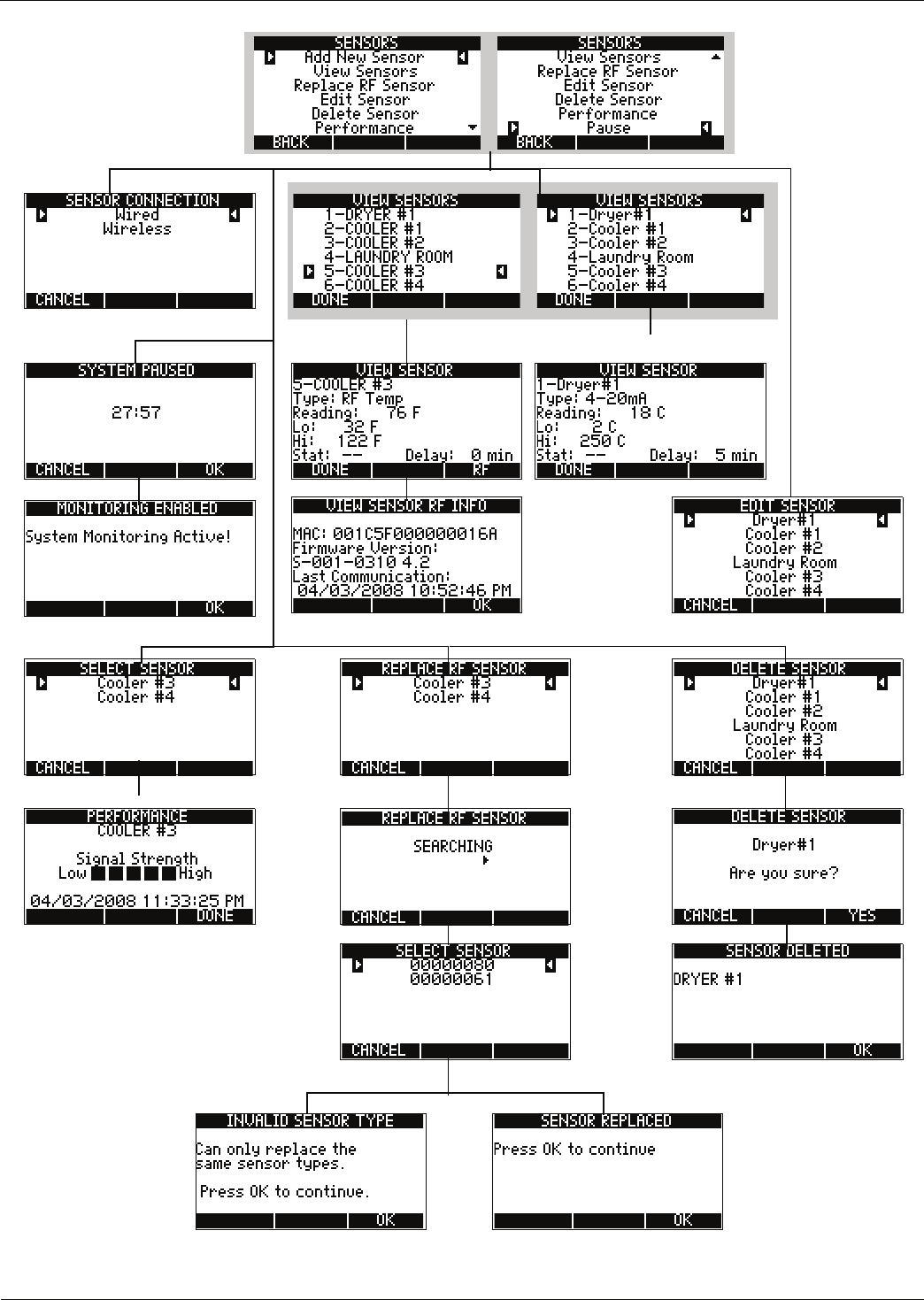
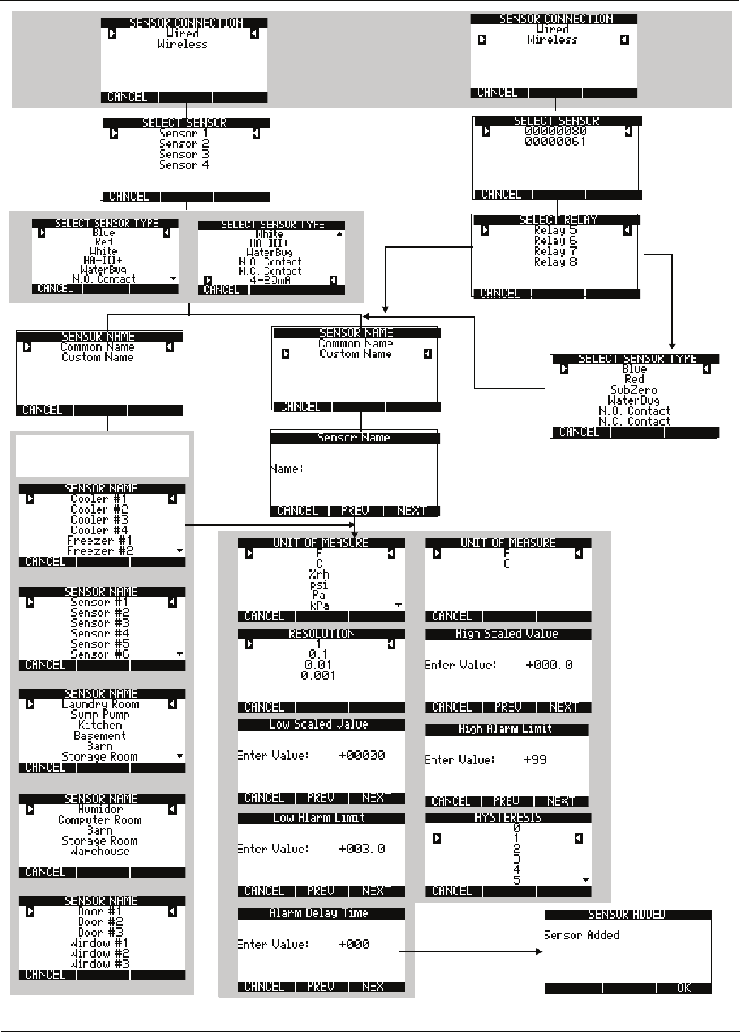
78 D-011-0152
Figure 20. Add New Sensor Screen Map
Common Name screen is
dependent on the sensor being
added.
If multi-function only
Parameter screens depend on
the sensor being installed.
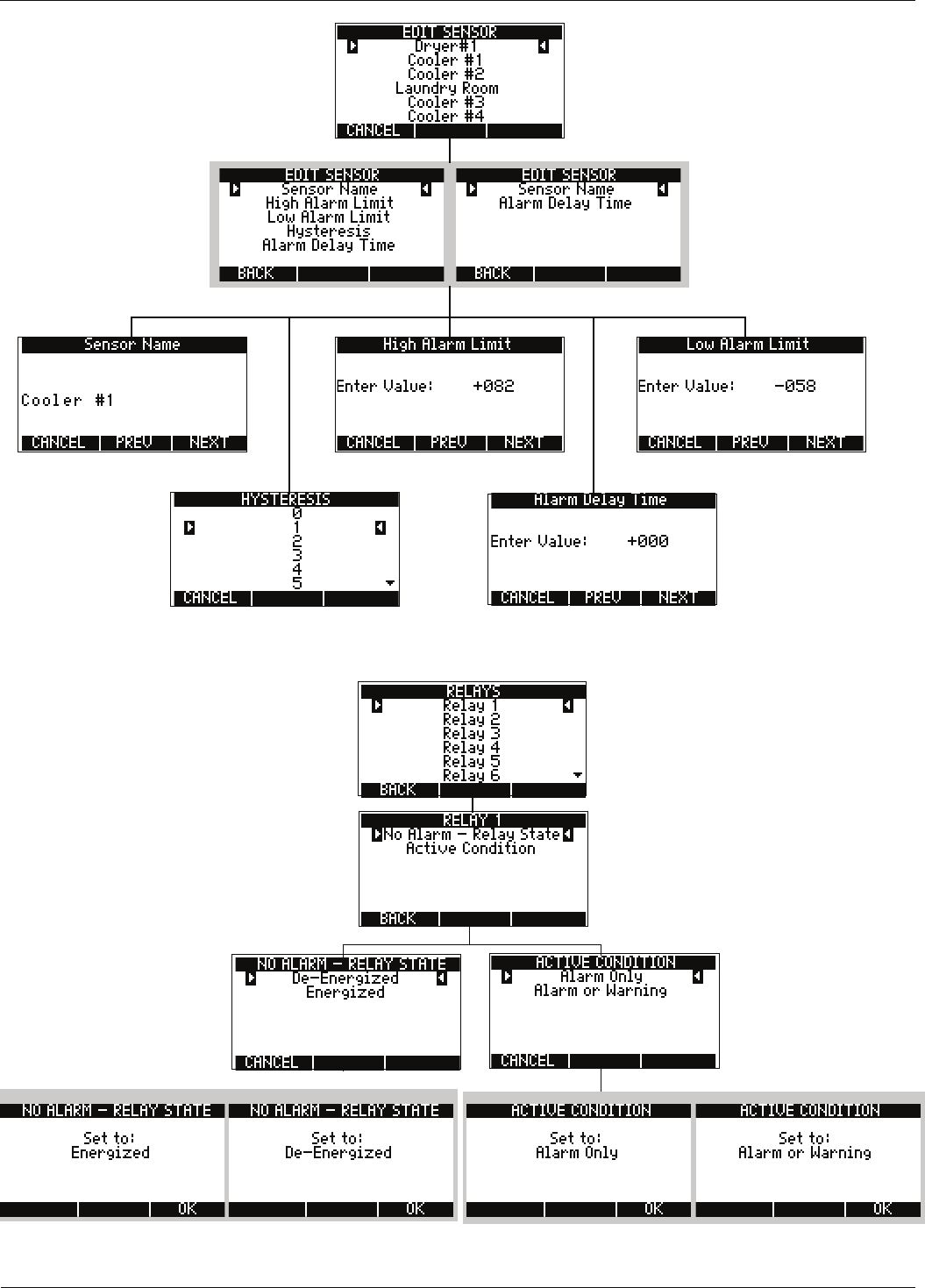
Appendix A: Screen Maps
D
-
011
-
0152
79
Figure 21. Edit Sensor Screen Map
Figure 22. Relay Screen Map
Screen displayed is dependent
on the sensor type.
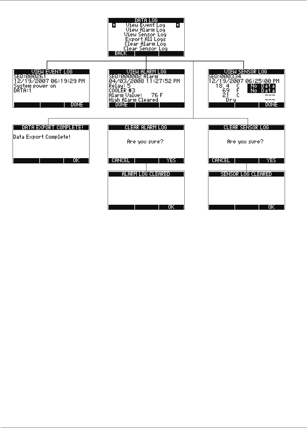
80 D-011-0152
Figure 23. Data Log Screen Map

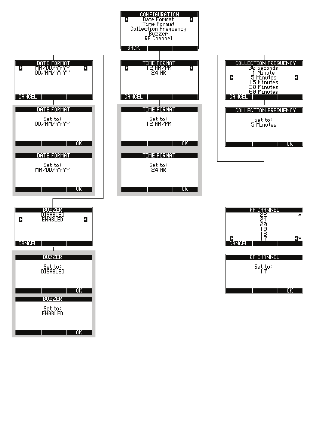
82 D-011-0152
Figure 25. Configuration Screen Map

Appendix B: Planning Worksheet
D
-
011
-
0152
83
Appendix B: Planning Worksheet
Note: Photocopy and complete a copy of this worksheet for each system.
Installation:
Room
Environmental Condition to
Monitor Acceptable Condition/Range Alarm Condition

84 D-011-0152
Appendix C: Wiring Diagram
D
-
011
-
0152
85
Appendix C: Wiring Diagram
Note: Photocopy and complete copy of this diagram for each EA800 to be installed in the system.
Power
In
Aux
Power
Out
J6
J5
Input 1
Input 2
Input 3
Input 4
(-)
+
(-)
+
(-)
+
(-)
+
(-)
+
(-)
+
Output 1
Output 2
Output 3
Output 4
Output 5
Output 6
Output 7
Output 8
Aux
NC
COM
NO
NC
COM
NO
NC
COM
NO
NC
COM
NO
NC
COM
NO
NC
COM
NO
NC
COM
NO
NC
COM
NO
NC
COM
NO
EA800 ___
Wire Color/
Designation Alarm Panel
Connection
Wire Color/
Designation
Sensor
Connection

86 D-011-0152

Appendix D: System Configuration Record
D
-
011
-
0152
87
Appendix D: System Configuration Record
Note: Photocopy this appendix and complete a copy for each EA800 base unit in the system.
EA800 Environmental Alarm System Configuration Form
Date of installation/change:
Name of Installation Company:
Phone number:
Name of installer (print):
EA800 identifier:
System Configuration (circle setting)
Date Format: MM/DD/YYYY or DD/MM/YYYY
Collection Frequency:
30s, 1min, 5 min, 15 min, 30 min, 60 min
Time Format: 12 hour or 24 hour
Channel: 11, 12, 13, 14, 15, 16, 17, 18, 19, 20, 21, 22, 23, 24,
25, 26
Buzzer: Enabled or Disabled
Sensor 1 Settings
Sensor
Model
Sensor
Name
Physical
Location Parameter Settings
Unit of Measure:
Operational Parameters:
Notes:
Resolution:
Low Scaled Value:
High Scaled Value:
Hysteresis:
Low Alarm Limit
High Alarm Limit:
Alarm Delay Time:
No Alarm - Relay State:
Active Condition:

88 D-011-0152
Sensor 2 Settings
Sensor
Model
Sensor
Name
Physical
Location Parameter Settings
Unit of Measure:
Operational Parameters:
Notes:
Resolution:
Low Scaled Value:
High Scaled Value:
Hysteresis:
Low Alarm Limit
High Alarm Limit:
Alarm Delay Time:
No Alarm - Relay State:
Active Condition:
Sensor 3 Settings
Sensor
Model
Sensor
Name
Physical
Location Parameter Setting
Unit of Measure:
Operational Parameters:
Notes:
Resolution:
Low Scaled Value:
High Scaled Value:
Hysteresis:
Low Alarm Limit
High Alarm Limit:
Alarm Delay Time:
No Alarm - Relay State:
Active Condition:
EA800 Environmental Alarm System Configuration Form

Appendix D: System Configuration Record
D
-
011
-
0152
89
Sensor 4 Settings
Sensor
Model
Sensor
Name
Physical
Location Parameter Settings
Unit of Measure:
Operational Parameters:
Notes:
Resolution:
Low Scaled Value:
High Scaled Value:
Hysteresis:
Low Alarm Limit
High Alarm Limit:
Alarm Delay Time:
No Alarm - Relay State:
Active Condition:
Sensor 5 Settings (wireless)
Sensor
Model
Sensor
Name
Physical
Location Parameter Settings
Unit of Measure:
Operational Parameters:
Installed LQI (in bars):
MAC Address:
Notes:
Resolution:
Low Scaled Value:
High Scaled Value:
Hysteresis:
Low Alarm Limit
High Alarm Limit:
Alarm Delay Time:
No Alarm - Relay State:
Active Condition:
EA800 Environmental Alarm System Configuration Form

90 D-011-0152
Sensor 6 Settings (wireless)
Sensor
Model
Sensor
Name
Physical
Location Parameter Settings
Unit of Measure:
Operational Parameters:
Installed LQI (in bars):
MAC Address:
Notes:
Resolution:
Low Scaled Value:
High Scaled Value:
Hysteresis:
Low Alarm Limit
High Alarm Limit:
Alarm Delay Time:
No Alarm - Relay State:
Active Condition:
Sensor 7 Settings (wireless)
Sensor
Model
Sensor
Name
Physical
Location Parameter Settings
Unit of Measure:
Operational Parameters:
Installed LQI (in bars):
MAC Address:
Notes:
Resolution:
Low Scaled Value:
High Scaled Value:
Hysteresis:
Low Alarm Limit
High Alarm Limit:
Alarm Delay Time:
No Alarm - Relay State:
Active Condition:
Sensor 8 Settings (wireless)
EA800 Environmental Alarm System Configuration Form

Appendix D: System Configuration Record
D
-
011
-
0152
91
Sensor
Model
Sensor
Name
Physical
Location Parameter Settings
Unit of Measure:
Operational Parameters:
Installed LQI (in bars):
MAC Address:
Notes:
Resolution:
Low Scaled Value:
High Scaled Value:
Hysteresis:
Low Alarm Limit
High Alarm Limit:
Alarm Delay Time:
No Alarm - Relay State:
Active Condition:
EA800 Environmental Alarm System Configuration Form

92 D-011-0152
Warranty and Service Information
Winland Electronics, Inc. ("Winland") warrants to the end user/purchaser that each product of its manufacture shall be free from
defects in material and factory workmanship for a period of two (2) years from the date of purchase, when properly installed and
operated under normal conditions according to Winland's instruction.
Winland's obligation under this warranty is limited to correcting, without charge, at its factory any part or parts thereof which shall be
returned to the factory, by the original purchaser, transportation charges prepaid, within one year of the date of purchase and which
upon examination, shall disclose to Winland's satisfaction to have been originally defective. Correction of such defects by repair to,
or supplying replacements for, defective parts shall constitute fulfillment of all Winland's obligations to purchaser under this limited
warranty. Repair service performed by Winland after one year from date of purchase will be for a reasonable service charge.
This limited warranty shall not apply to any of Winland's products which have been subject to misuse, negligence or accident or
which have been repaired or altered outside of Winland's factory.
Winland shall not be liable for loss, damage or expense resulting, directly or indirectly, from the use of its products or any other
cause.
THIS WARRANTY IS IN LIEU OF ALL OTHER WARRANTIES, EXPRESS OR IMPLIED, INCLUDING, WITHOUT LIMITATION,
ANY WARRANTIES OF MERCHANTABILITY, FITNESS FOR PARTICULAR PURPOSES, NON-INFRINGEMENT AND TITLE,
AND ANY WARRANTIES ARISING FROM COURSE OF DEALING, USAGE OF TRADE OR OTHERWISE. ALL OTHER
REPRESENTATIONS MADE TO THE END USER/PURCHASER BY ANY OTHER PARTY ARE ALSO EXCLUDED.
WINLAND SHALL NOT BE LIABLE TO ANY PERSON FOR INDIRECT, SPECIAL, INCIDENTAL OR CONSEQUENTIAL
DAMAGES OF ANY DESCRIPTION, WHETHER ARISING OUT OF WARRANTY OR OTHER CONTRACT, NEGLIGENCE OR
OTHER TORT, OR OTHERWISE. Under no circumstances shall Winland's liability under this limited warranty exceed the purchase
price paid by the end user/purchaser for the product.
No person, agent or dealer is authorized to give warranties on behalf of Winland nor to assume for Winland any other liability in
connection with any of its products.
Duplication or distribution of this manual and any information contained within is strictly prohibited without the express written
permission of Winland Electronics, Inc. To order additional copies of this manual, or other related manuals, contact Winland
Electronics Customer Service at 1-800-635-4269.
The information in this document has been carefully examined and is believed to be entirely reliable. However, no responsibility is
assumed for inaccuracies.
EnviroAlert, and the Winland logo, are trademarks of Winland Electronics, Inc. in the U.S. Other product names and trademarks
appearing in this manual are the property of their respective owners.

Manufactured in the U.S.A by
Winland Electronics
1950 Excel Drive, Mankato, MN, 56001
Outside MN Phone: 1-800-635-4269
Phone: 507-625-7231
Fax: 507-387-2488
©Winland Electronics, Inc. 2008
www.winland.com
D-011-0152 Rev. A
