Envision Peripherals Water Furnace Im1609 08 Users Manual
IM1609 08 to the manual 1b6ce8f5-7fee-4ed4-a373-930cdc970a53
2015-02-02
: Envision-Peripherals Envision-Peripherals-Water-Furnace-Im1609-08-Users-Manual-396796 envision-peripherals-water-furnace-im1609-08-users-manual-396796 envision-peripherals pdf
Open the PDF directly: View PDF ![]() .
.
Page Count: 48
IM1609 10/08
Installation Information
Water Piping Connections
Electrical
Startup Procedures
Troubleshooting
Preventive Maintenance
Envision Console Installation Manual
Geothermal/Water Source Heat Pumps
• R-410A Refrigerant
• 0.75-1.5 Ton Single Speed
CONSOLE

2
ENVISION CONSOLE INSTALLATION MANUAL
Table of Contents
Model Nomenclature........................................................... 3
General Installation Information ................................................. 4
Dimensional Data............................................................ 5-11
Installation Steps ........................................................... 12-15
System Cleaning and Flushing...................................................16
Open Loop Ground Water Systems ..............................................17
Electrical Connections .........................................................18
Auxiliary Heat Ratings .........................................................18
Unit Electrical Data ............................................................19
Fan Performance Table .........................................................19
Wiring Schematics.........................................................20-24
Envision Console Controls .................................................. 25-39
Unit Startup Notes............................................................40
Unit Startup Checklist/Unit Startup Steps.........................................41
Unit Operating Parameters .................................................... 42
Unit Operating Limits .........................................................42
Startup/Troubleshooting Form .................................................43
Pressure Drop................................................................44
Preventive Maintenance .......................................................45
Replacement Procedures ......................................................45
3
ENVISION CONSOLE INSTALLATION MANUAL
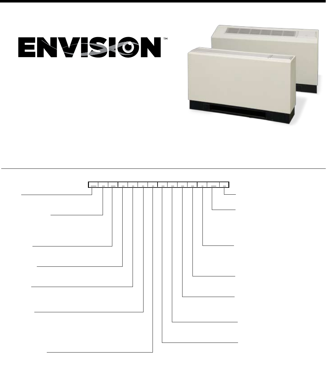
Model Nomenclature
CONSOLES
1-2 3 4-5 6 7 8 9 10 11 12 13 14 15-16 17
NC C 09 L 0 1 1 C N N A 1 SS A
Family Vintage
NC = Envision Console A = Current
Non-Standard Option Details
Cabinet Configuration SS = Standard Option
C = Chassis Only
W = Chassis with Cabinet
S = Chassis with Slope Top
E = Chassis with Extended Slope Top
Unit Capacity Air Coil / Insulation Options
MBTUH @ 86
o
F EWT 1 = Formishield / Extended Range
09, 12, 15, 18 2 = Formishield / Standard Range
3 = No Coating / Extended Range
Piping Option 4 = No Coating / Standard Range
L = Left
R= Right (N/A with chassis only) Sound Kit
A = None
Voltage B = Blanket
0 = 208-230/60/1
2 = 265/60/1 Auxilliary Electric heat
N = None
C = 2.0 kW (09-12)*
Unit Control D = 3.0 kW (15-18)*
1 = CCM
2 = Versatec Motorized Oustide Air Damper (Field Installed)
4 = FX10 std. no communication - (only w/ t-stat control option 2) N = None
5 = FX10 w/Open N2 Com Card - (only w/ t-stat control option 2) M = Motorized Damper
6 = FX10 w/Lonworks Com Card - (only w/ t-stat control option 2)
7 = FX10 w/BacNet Com Card - (only w/ t-stat control option 2) Coax Options
C = Copper
Thermostat Control N = Cupronickel
1 = Unit mounted t-stat
2 = Remote wall-mounted t-stat

4
ENVISION CONSOLE INSTALLATION MANUAL
Safety Considerations
WARNING: Before performing service or main-
tenance operations on a system, turn off main
power switches to the indoor unit. If applicable,
turn off the accessory heater power switch. Elec-
trical shock could cause personal injury.
Installing and servicing heating and air conditioning
equipment can be hazardous due to system pressure and
electrical components. Only trained and qualified service
personnel should install, repair or service heating and air
conditioning equipment. Untrained personnel can perform
the basic maintenance functions of cleaning coils and clean-
ing and replacing filters. All other operations should be
performed by trained service personnel. When working on
heating and air conditioning equipment, observe precau-
tions in the literature, tags and labels attached to the unit
and other safety precautions that may apply.
Follow all safety codes. Wear safety glasses and work
gloves. Use a quenching cloth for brazing operations and
have a fire extinguisher available.
Moving and Storage
Move units in the normal “up” orientation. Do not stack
units. When the equipment is received, all items should be
carefully checked against the bill of lading to be sure all
crates and cartons have been received. Examine units for
shipping damage, removing the units from the packag-
ing if necessary. Units in question should also be internally
inspected. If any damage is noted, the carrier should make
the proper notation on the delivery receipt, acknowledging
the damage.
Water Piping
The proper water flow must be provided to each unit when-
ever the unit operates. To assure proper flow, use pressure/
temperature ports to determine the flow rate. These ports
should be located at the supply and return water connec-
tions on the unit. The proper flow rate cannot be accurately
set without measuring the water pressure drop through the
refrigerant-to-water heat exchanger.
All source water connections on commercial units are fit-
tings that accept a male pipe thread (MPT). Insert the con-
nectors by hand, then tighten the fitting with a wrench to
provide a leakproof joint. When connecting to an open loop
(groundwater) system, thread any copper MPT fitting into
the connector and tighten in the same manner as described
above.
Refrigerant Systems
To maintain sealed circuit integrity, do not install service
gauges unless unit opertion appears abnormal. Compare
the change in temperature on the air side as well as the wa-
ter side to the Unit Operating Parameters tables. If the unit’s
performance is not within the ranges listed, and the airflow
and water flow are known to be correct, gauges should
then be installed and superheat and subcooling numbers
calculated. If superheat and subcooling are outside recom-
mended ranges, an adjustment to therefrigerant charge may
be necessary.
General Installation Information
5
ENVISION CONSOLE INSTALLATION MANUAL
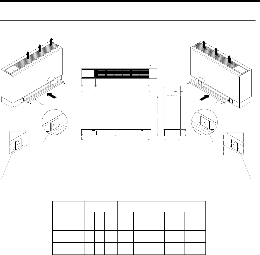
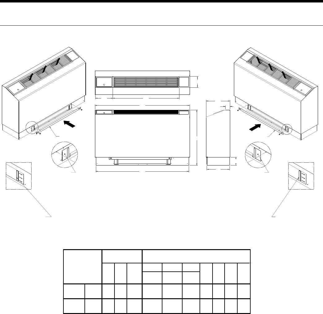
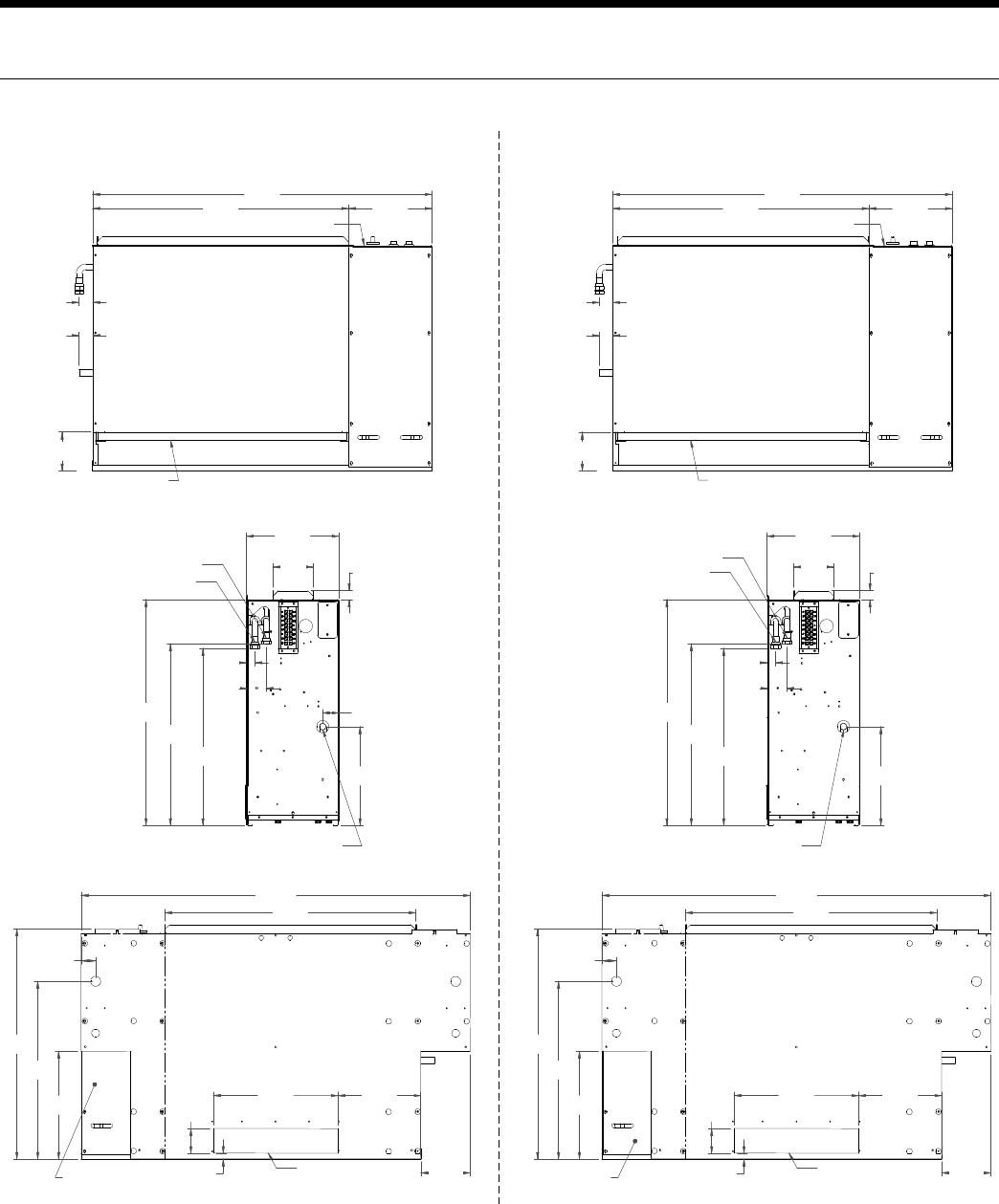
NCW09-18
Overall Cabinet
Flat Top
Configuration
A B C D E F G H I J
Width Depth Height Grille Lid Grille
Length
Grille
Width
in. 45.0 10.8 25.7 9.2 35.0 6.1 2.3 44.1 10.3 4.3
cm. 114.3 27.3 65.2 23.4 88.9 15.6 5.8 112.0 26.0 10.9
in. 50.0 12.3 25.7 9.2 35.0 6.1 3.3 49.1 11.8 4.3
cm. 127.0 31.1 65.2 23.4 88.9 15.6 8.3 124.7 29.8 10.9
09-12
15-18
4
0
5
7
8
1
32
/
6
47:B3@0@/193B 47:B3@0@/193B
@756B@3BC@<
B=>
4@=<B
:34B@3BC@<
23B/7:0
BE7AB3FB3<232
B/00/19/<2
4=@B6C<B7:
B/00@3/9A=44
=<:G0@3/9=44
B/0A/;3A723/A
5@7::3:72/AA6=E<
23B/7:0
BE7AB3FB3<232B/0
0/19/<24=@B6C<B7:
B/00@3/9A=44
=<:G0@3/9=44
B/0A/;3A723/A
5@7::3:72/AA6=E<
0/
@3;=D3>:/AB71AB@7>
4@=;0@=93<B/0/<2
@3>:/13=<0@=93<
3253=4:35/AA6=E<
@3;=D3>:/AB71AB@7>
4@=;0@=93<B/0/<2
@3>:/13=<0@=93<
3253=4:35/AA6=E<
Dimensional Data - Flat Top Cabinet
6
ENVISION CONSOLE INSTALLATION MANUAL
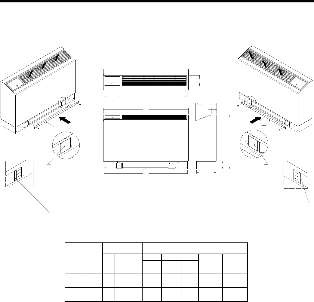
NCS09-18
Overall Cabinet
Slope Top
Configuration
A B C D E F G H I J
Width Depth Height Grille Lid Grille
Length
Grille
Width
in. 45.0 11.1 28.6 9.2 35.0 6.1 2.8 44.1 10.3 4.3
cm. 114.3 28.2 72.6 23.4 88.9 15.6 7.2 112.0 26.0 10.9
in. 50.0 12.6 29.1 9.2 35.0 6.1 2.5 49.1 11.8 4.3
cm. 127.0 32.0 73.9 23.4 88.9 15.6 6.4 124.7 29.8 10.9
09-12
15-18
@3;=D3>:/AB71AB@7>
4@=;0@=93<B/0/<2
@3>:/13=<0@=93<
3253=4:35/AA6=E<
67
8
1
4
3
/
2
5
0
@756B@3BC@<
B=>
4@=<B
:34B@3BC@<
23B/7:0
BE7AB3FB3<232B/0
0/19/<24=@B6C<B7:
B/00@3/9A=44
=<:G0@3/9=44
B/0A/;3A723/A
5@7::3:72/AA6=E<
23B/7:/
BE7AB3FB3<232B/0
0/19/<24=@B6C<B7:
B/00@3/9A=44
=<:G0@3/9=44
B/0A/;3A723/A
5@7::3:72/AA6=E<
@3;=D3>:/AB71AB@7>
4@=;0@=93<B/0/<2
@3>:/13=<0@=93<
3253=4:35/AA6=E<
0
/
47:B3@0@/193B
47:B3@0@/193B
Dimensional Data - Slope Top Cabinet
7
ENVISION CONSOLE INSTALLATION MANUAL
NCE09-18
@3;=D3>:/AB71AB@7>
4@=;0@=93<B/0/<2
@3>:/13=<0@=93<
3253=4:35/AA6=E<
Overall Cabinet
Ext. Slope Top
Configuration
A B C D E F G H I J
Width Depth Height Grille Lid Grille
Length
Grille
Width
in. 50.0 12.6 29.1 9.2 35.0 6.1 2.4 49.1 12.0 4.3
cm. 127.0 32.0 73.9 23.4 88.9 15.6 6.1 124.7 30.5 10.9
in. 55.0 12.6 29.1 9.2 35.0 6.1 2.5 54.1 11.8 4.3
cm. 139.7 32.0 73.9 23.4 88.9 15.6 6.4 137.4 29.8 10.9
09-12
15-18
47:B3@0@/193B47:B3@0@/193B
/
2 3
1
67
8
4
0
5
/0
@756B@3BC@< B=>
4@=<B
:34B@3BC@<
23B/7:0
BE7AB3FB3<232B/0
0/19/<24=@B6C<B7:
B/00@3/9A=44
=<:G0@3/9=44
B/0A/;3A723/A
5@7::3:72/AA6=E<
23B/7:/
BE7AB3FB3<232B/0
0/19/<24=@B6C<B7:
B/00@3/9A=44
=<:G0@3/9=44
B/0A/;3A723/A
5@7::3:72/AA6=E<
@3;=D3>:/AB71AB@7>
4@=;0@=93<B/0/<2
@3>:/13=<0@=93<
3253=4:35/AA6=E<
Dimensional Data - Extended Slope Top Cabinet
8
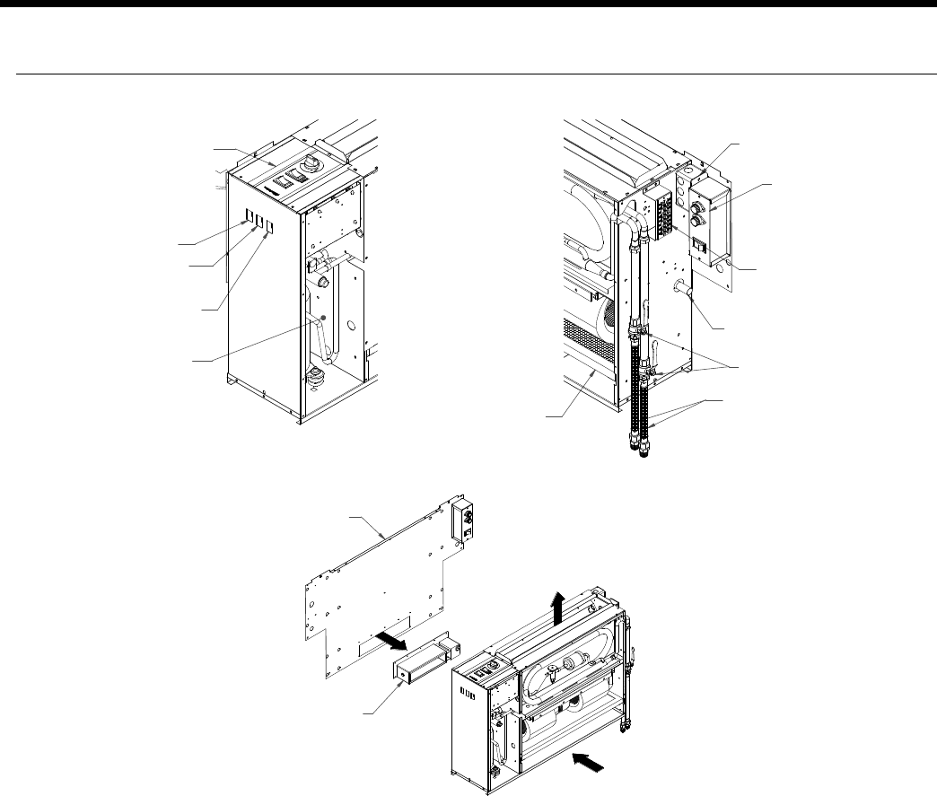
ENVISION CONSOLE INSTALLATION MANUAL
1=<B@=:>/<3:
@3;=D34=@/113AA
B=1=<B@=:0=F
2/;>3@=<=44AE7B16
1=;>@3AA=@
/113AA>/<3:
@3;=D324=@
1:/@7BG
0=B6A723A
3:31B@7163/B;=23
<=@;/:0=7:3@:3AA
AE7B16=>B7=</:
4/<=>B7=<AE7B16
=>B7=</:0/19>:/B3
@3?C7@324=@
2/;>3@7<AB/::/B7=<
=CBA723/7@
2/;>3@=>B7=<
473:27<AB/::32
:=ED=:B/53
B3@;7</:A
4F@3;=B3E/::
AB/B=>B7=<A=<:G
=>B7=</:
4CA32
<=<4CA32
27A1=<<31B
=>B7=</:
0/::D/:D3A
=>B7=</:
6=A397BA
1=<23<A/B3
2@/7<1=<<31B7=<
47:B3@
6/<2G0=F
Dimensional Data - Right Return Controls Detail
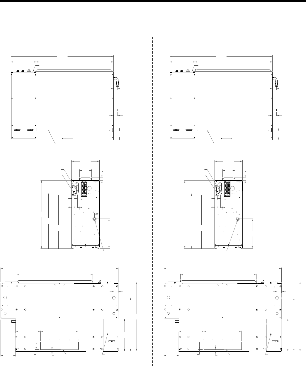
9
ENVISION CONSOLE INSTALLATION MANUAL
0:=E3@/113AA>/<3:
1=;>@3AA=@
/113AA>/<3:
!%&&
'$
&#
% "
#
!&
#
!&
"!%
'!&
!&
47:B3@
1=<B@=:>/<3:
# #
$"
&$
!
$
#
%&
"#
%'
"#
"
#
"
#""
#&
1=<23<A/B3
2@/7<1=<<31B7=<
E/B3@=CB Þ4>B
E/B3@7< Þ4>B
=>B7=</:0/19>:/B3
1=;>@3AA=@
/113AA>/<3:
"!!%
&
%
' #
!# !'
!#!
#$#
$#
'&!
#"
$"
"
!
!$
$$
%
%#
%
##
" 2/;>3@=>3<7<5
<1'
0:=E3@/113AA>/<3:
1=;>@3AA=@
/113AA>/<3:
" &&
&'
!"
&$"
#
!&
#
!&
"!
&&&
$
47:B3@
1=<B@=:>/<3:
# #
$"
&$
%#
'&
#
!#
"#
"
#
$
# !
'#
"'#
1=<23<A/B3
2@/7<1=<<31B7=<
E/B3@=CB Þ4>B
E/B3@7< Þ4>B
=>B7=</:0/19>:/B3
1=;>@3AA=@
/113AA>/<3:
"& #
$
!!
&!&
%&
'' !'
!#!
#&
$##
#&
$
"
&
!'
&!
%#
%
#"
!% 2/;>3@=>3<7<5
<1#&
Dimensional Data - Right Return Chassis
Data = inches (cm)
10
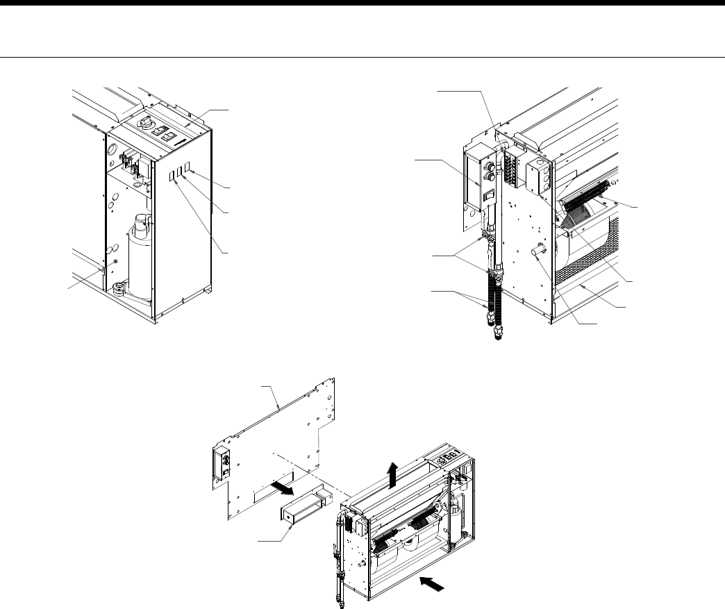
ENVISION CONSOLE INSTALLATION MANUAL
:=ED=:B/53
B3@;7</:A
4F@3;=B3E/::
AB/B=>B7=<A=<:G
=>B7=</:
4CA32
<=<4CA32
27A1=<<31B
=>B7=</:
0/::D/:D3A
=>B7=</:
6=A397BA
1=<23<A/B3
2@/7<1=<<31B7=<
47:B3@
6/<2G0=F
=>B7=</:
3:31B@7163/B
=>B7=</:0/19>:/B3
@3?C7@324=@
2/;>3@7<AB/::/B7=<
=CBA723/7@
2/;>3@=>B7=<
473:27<AB/::32
1=<B@=:>/<3:
@3;=D34=@/113AA
B=1=<B@=:0=F
2/;>3@=<=44AE7B16
1=;>@3AA=@
/113AA>/<3:
@3;=D324=@
1:/@7BG
0=B6A723A
3:31B@7163/B;=23
<=@;/:0=7:3@:3AA
AE7B16=>B7=</:
4/<=>B7=<AE7B16
Dimensional Data - Left Return Controls Detail
11
ENVISION CONSOLE INSTALLATION MANUAL
'!&
!&
&#
% "
#
!&
#
!&
"!%
!%&&
'$
0:=E3@/113AA>/<3:
1=;>@3AA=@
/113AA>/<3:
47:B3@
1=<B@=:>/<3:
#
!
$
"#
"
&$
#
# #
$"
"
#""
#&
%&
"#
%'
1=<23<A/B3
2@/7<1=<<31B7=<
E/B3@=CB Þ4>B
E/B3@7< Þ4>B
&
%
!'
!#! ' #
!#
%#
%
!
!#
$$
% ##
"
=>B7=</:0/19>:/B3
1=;>@3AA=@
/113AA>/<3:
2/;>3@=>3<7<5
"!!%
$
"
#$#
$#
'&!
#"
<1'
&&&
$
!"
&$"
#
!&
#
!&
"!
" &&
&'
0:=E3@/113AA>/<3:
1=;>@3AA=@
/113AA>/<3:
47:B3@
1=<B@=:>/<3:
#
%#
$
"#
"
&$
#
# #
$"
$
# !
'#
"'#
!#
1=<23<A/B3
2@/7<1=<<31B7=<
E/B3@=CB Þ4>B
E/B3@7< Þ4>B
!!
&!&
!'
!#! %&
''
%#
%
&
!'
&!
##
"
=>B7=</:0/19>:/B3
1=;>@3AA=@
/113AA>/<3:
2/;>3@=>3<7<5
"& #
$
$
"
#&
$##
#&
<1#&
Dimensional Data - Left Return Chassis
Data = inches (cm)
12
ENVISION CONSOLE INSTALLATION MANUAL
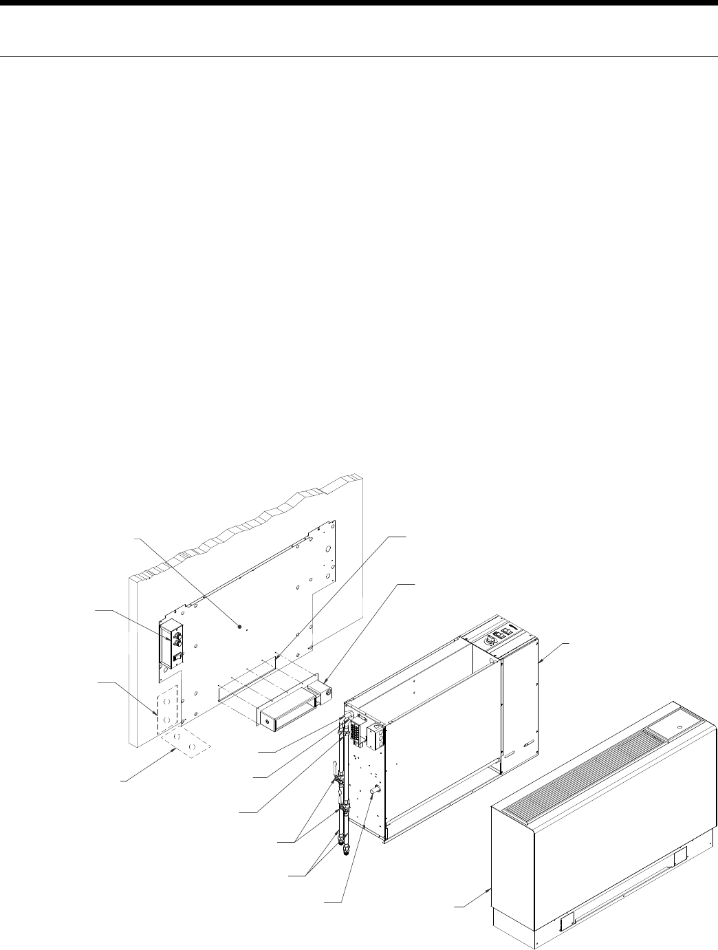
Installation Steps
Step 1: Unpack Equipment and Inspect for Damage
Step 2: Determine Equipment Location
Choose level flooring surface (Correctable with shims. Do not pitch towards drain.)•
Location of wall support and fasteners required to secure chassis backplate.•
Easy access for both installation and service. •
Consider availability and ease of wiring, water piping and condensate drain.•
No obstructions to block airflow in front of the unit.•
Step 3: Mark Unit Position
Ensure that floor is level. If shims are required, make sure that the entire compressor compartment area is uniformly •
shimmed and that the backplate mounting height is increased by the thickness of the shims used.
Position backplate in desired equipment location. To further reduce the operating sound level of the unit, 1/8-inch thick •
rubber matting may be placed under the chassis to eliminate vibration on hard flooring surfaces. (Make sure back plate
is level).
Mark and cut floor or wall penetrations for electrical wiring, water and condensate piping.•
Optional Electrical Disconnect and Motorized Outside Air Damper
Mark and cut wall penetrations for field fabricated outside air duct sleeve.•
Align mounting holes with backplate and attach with screws supplied.•
1=<A=:3
1/07<3B
1=<A=:3
16/AA7A
1=<23<A/B3
2@/7<:=1/B7=<
=>B7=</:6=A3A
0/::D/:D3A
=>B7=</:
>B>:C5A
=>B7=</:
E/B3@
=CB
E/B3@
7<
1=<A=:31/07<3B
0/19>:/B3
=>B7=</:
E/::>3<3B@/B7=<
4=@E/B3@1=<<31B7=<
4:==@>3<3B@/B7=<
4=@E/B3@1=<<31B7=<
4CA323:31B@71/:
27A1=<<31B=>B7=</:
;=B=@7H32
2/;>3@
=>B7=</:
;=B=@7H32
2/;>3@
=>3<7<5
Figure 1
13
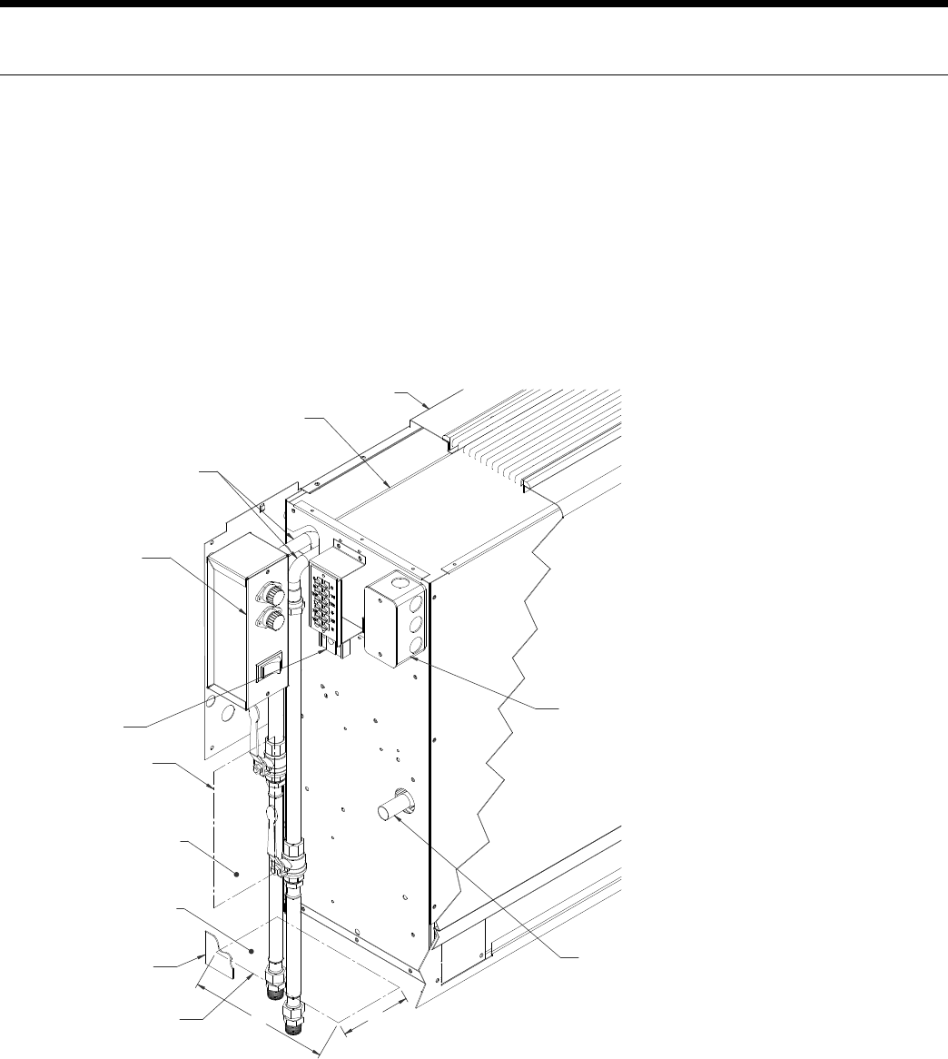
ENVISION CONSOLE INSTALLATION MANUAL
Installation Steps (cont.)
Step 4: Provide Water and Condensate Drain Connections
A two-pipe reverse return piping configuration is recommended as it equalizes the piping circuit lengths and delivers •
even water flow to each unit. A direct return piping configuration may be used, but it may be difficult to achieve and
maintain proper water flow to the units.
An air vent must be installed in the water distribution system.•
The supply and return water piping should be run through the wall or floor penetration and terminate with a ball valve. •
The piping material used must comply with all local codes.
Refer to: • System Cleaning and Flushing procedures.
Pipe Locations
Figure 2
1=<A=:3
1/07<3B
1=<A=:3
16/AA7A
1=<23<A/B3
2@/7<:=1/B7=<
E/B3@1=<<31B7=<A
B/@53B/@3/4=@
E/::>3<3B@/B7=<
4CA323:31B@71/:
27A1=<<31B=>B7=</:
#Þf&Þ/@3//>>=F Þ
4@=;3253=416/AA7A
Þ4@=;4@=<B3253
=41/07<3B
#Þ
&Þ
B/@53B/@3/4=@
4:==@>3<3B@/B7=<
1/07<3B3FB3<2A
B=B67A>=7<B
#Þf&Þ/@3//>>=F Þ
4@=;3253=416/AA7A
!Þ4@=;4:==@
"D/113AA=@G
3:31B@71/:
8C<1B7=<0=F

14
ENVISION CONSOLE INSTALLATION MANUAL
Installation Steps (cont.)
Step 5: Provide Line Voltage Wiring
Check unit data plate located on control side of chassis for ampacity and fuse size.•
Remove electrical knockouts from chassis backplate.•
Run line voltage wiring through knockout and secure wiring to backplate or disconnect.•
Step 6: Chassis Installation
Level and secure backplate to wall.•
Position the chassis against back plate. Drive (2) screws through holes in lip of backplate into top flange of chassis.•
Step 7: Final Electrical Connection
Install flexible electrical conduit between the backplate or electrical disconnect and the unit mounted junction box. •
Make final wiring connections in disconnect and junction box, taking care to replace all covers when done. Wiring must •
conform to NEC and/or all local codes. Refer to Electrical Data.
NOTE: It is necessary to make final wiring connections prior to securing unit chassis to back plate on right-hand piping
models with electrical disconnect.
Step 8: Final Water Connection
For ease of installation and sound attenuation, high pressure (recommended) flexible hoses with a swivel fitting should •
be provided. Apply Teflon® tape or sealant compound to threaded hose fittings.
Combination shut-off/balancing valves should be installed on both the supply and return water lines of the unit.•
Flow control valves should be installed on the water discharge line.•
It is recommended that P/T ports be installed on the supply and return water lines.•
Step 9: Set Unit Controls
Locate the “continuous fan/cycle fan” switch within the electrical compartment of the chassis and set to desired position.•
(Remote wall thermostat units do not use this optional switch.)
Optional Control Settings-•
Remote Thermostat - Run low voltage wiring from unit to the desired thermostat location.
Mount and wire thermostat according to manufacturer’s recommendations.
Motorized Outside Air Damper - Locate the “damper on/damper off” damper switch within the electrical compartment
of the chassis and set to desired position.
Emergency Electrical Heat - Locate the “electric heat/normal/boilerless” control switch within the electrical compart-
ment of the chassis and set to desired position.
Step 10: Secure the Cabinet Cover
Position and lower cabinet over unit chassis. Apply pressure to the front of the cabinet to ensure that the back lip of the •
cabinet hooks over the tabs provided on the backplate.
Secure cabinet to chassis with mounting screws provided.•
Step 11: Perform Final Unit Check
Measure the pressure drop across the water coil and monitor water or air temperatures in both heating and cooling •
modes. The measured values should fall within the acceptable ranges shown in the Startup Performance table.
15
ENVISION CONSOLE INSTALLATION MANUAL
Installation Steps (cont.)
1
Top view
Side view
Figure 3
2
Field Converting Console
Chassis is normally configured with controls on right end and piping on left end (see Figure 3 top view). In this position
panel number 1 would be positioned against wall or back plate. Unit may also be turned 180° against wall or back plate. In
this position controls will be on left end and piping on right end panel number 2 would be positioned against wall or back
plate. Chassis must be enclosed with an approved cabinet enclosure.
Remove 4 screws from front kick panel on cabinet.1.
Remove cabinet from chassis by lifting and sliding cabinet 2.
straight up.
Remove grille assembly from cabinet by removing 4 screws from 3.
brackets located on the bottom of the grille and door assemblies.
Replace grille/door assemblies into cabinet repositioning pieces 4.
1, 2, and 3 into the locations directly opposite the original positions.
Secure by replacing mounting brackets. (Note: Be sure that louvers
on the grille assembly are facing the proper direction when
replacing the grille section.)
Replace grille/frame assembly into cabinet, and secure by replacing 5.
mounting brackets.
Replace cabinet by sliding it down over the top of the chassis.6.
Remove tab on leg that extends into return air opening. When the 7.
grille side of the cabinet is flat against chassis there will be 4
holes that line up in the leg section. Only use 1 hole for alignment
for opposite side of grille. (Note: The tab can be removed by
twisting back and forth until it breaks off.)
Remove plastic strip from tab and replace on rough edge that the 8.
tab was removed from.
Replace screws in font kick panel to secure cabinet to chassis.9.
Mount filter bracket in designated opening area. (Note: The filter 10.
bracket will only fit in one direction if cabinet is installed properly.)
Figure 4
4
2
1
3
5
Depends on Cabinet Size
16
ENVISION CONSOLE INSTALLATION MANUAL
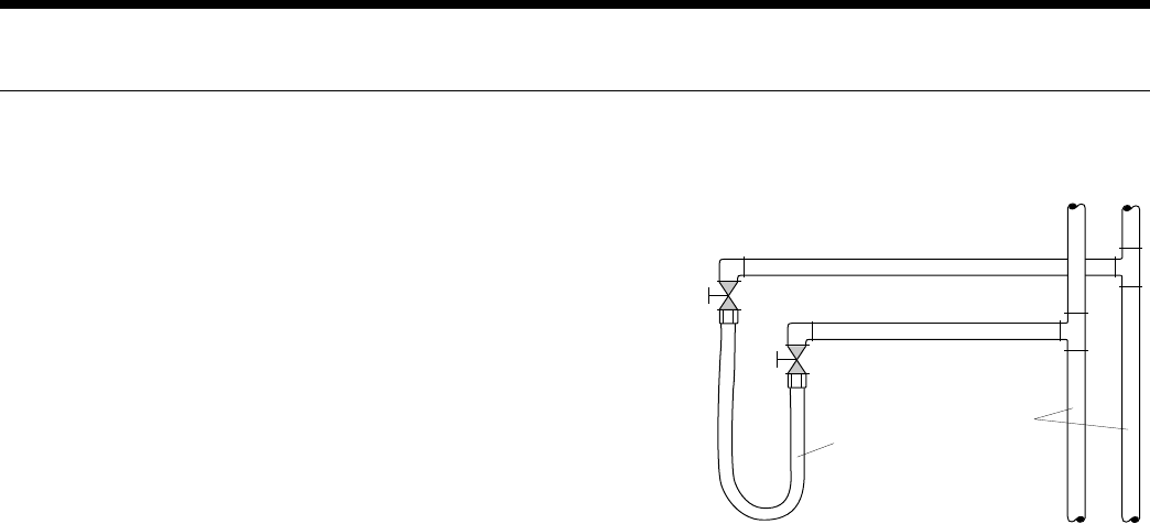
System Cleaning and Flushing
Cleaning and Flushing
Prior to start up of any heat pump, the water circulating system must be
cleaned and flushed of all dirt and debris.
If the system is equipped with water shutoff valves, the supply and
return runouts must be connected together at each unit location (This
will prevent the introduction of dirt into the unit, see Figure 7). The
system should be filled at the water make-up connection with all air
vents open. After filling, vents should be closed.
The contractor should start the main circulator with the pressure reduc-
ing valve makeup open. Vents should be checked in sequence to bleed
off any trapped air and to verify circulation through all components of
the system.
As water circulates through the system, the contractor should check
and repair any leaks found in the piping system. Drain(s) at the lowest
point(s) in the system should be opened for initial flush and blowdown, making sure water fill valves are set at the same
rate. Check the pressure gauge at the pump suction and manually adjust the make-up water valve to hold the same posi-
tive pressure both before and after opening the drain valves. Flushing should continue for at least two hours, or longer if
required, until drain water is clean and clear.
The supplemental heater and/or circulator pump, if used, should be shut off. All drains and vents should be opened to
completely drain the system. Short-circuited supply and return runouts should now be connected to the unit supply and
return connections.
Refill the system with clean water. Test the system water for acidity and treat as required to leave the water slightly alkaline
(pH 7.5 to 8.5). The specified percentage of antifreeze may also be added at this time. Use commercial grade antifreeze
designed for HVAC systems only. Environol™ brand antifreeze is recommended..
Once the system has been filled with clean water and antifreeze (if used), precautions should be taken to protect the sys-
tem from dirty water conditions. Dirty water will result in system-wide degradation of performance, and solids may clog
valves, strainers, flow regulators, etc. Additionally, the heat exchanger may become clogged which reduces compressor
service life and can cause premature unit failure.
In boiler/tower application, set the loop control panel set points to desired temperatures. Supply power to all motors and
start the circulating pumps. After full flow has been established through all components including the heat rejector (re-
gardless of season), air vented and loop temperatures stabilized, each of the units will be ready for check, test and start up
and for air and water balancing.
Ground Source Loop System Checkout
Once piping is completed between the unit pumping system and ground loop, final purging and charging of the loop is
needed. A high pressure pump is needed to achieve adequate flow velocity in the loop to purge air and dirt particles from
the loop itself. Antifreeze solution is used in most areas to prevent freezing. Flush the system adequately to remove as
much air as possible; then pressurize the loop to a static pressure of 40-50 PSI (summer) or 50-75 PSI (winter). This is
normally adequate for good system operation. Loop static pressure may decrease soon after initial installation, due to pipe
expansion and loop temperature change. Running the unit for at least 30 minutes after the system has been completely
purged of air will allow for the “break-in” period. It may be necessary to adjust static loop pressure (by adding water) after
the unit has run for the first time. Loop static pressure will also fluctuate with the seasons. Pressures will be higher in the
winter months than during the cooling season. This fluctuation is normal and should be considered when charging the
system initially.
Insure the pump provides adequate flow through the unit by checking pressure drop across the heat exchanger.
Usually 2.25-3.0 GPM of flow per ton of cooling capacity is recommended in earth loop applications.
Return Runout
Supply Runout
Mains
Rubber Hose
Runouts Initially
Connected Together
Figure 7: Flushing with Water
Shutoff Valve Equipped Systems
17
ENVISION CONSOLE INSTALLATION MANUAL
Open Loop Ground Water Systems
Always maintain water pressure in the heat exchanger by placing water control valves at the outlet of the unit to prevent
mineral precipitation. Use a closed, bladder-type expansion tank to minimize mineral formation due to air exposure. Insure
proper water flow through the unit by checking pressure drop across the heat exchanger and comparing it to the figures in
unit capacity data tables in the specification catalog. 1.5-2 GPM of flow per ton of cooling capacity is recommended in open
loop applications.
Discharge water from the unit is not contaminated in any manner and can be disposed of in various ways, depending on
local codes, i.e. recharge well, storm sewer, drain field, adjacent stream or pond, etc. Most local codes forbid the use of
sanitary sewer for disposal. Consult your local building and zoning departments to assure compliance in your area.
Note: For open loop/groundwater systems or systems that do not contain an antifreeze solution, set SW1-Switch #2 to the
“WELL” position (Refer to the Dip Switch Field Selection table). Slow opening/closing solenoid valves (type VM) are recom-
mended to eliminate water hammer.
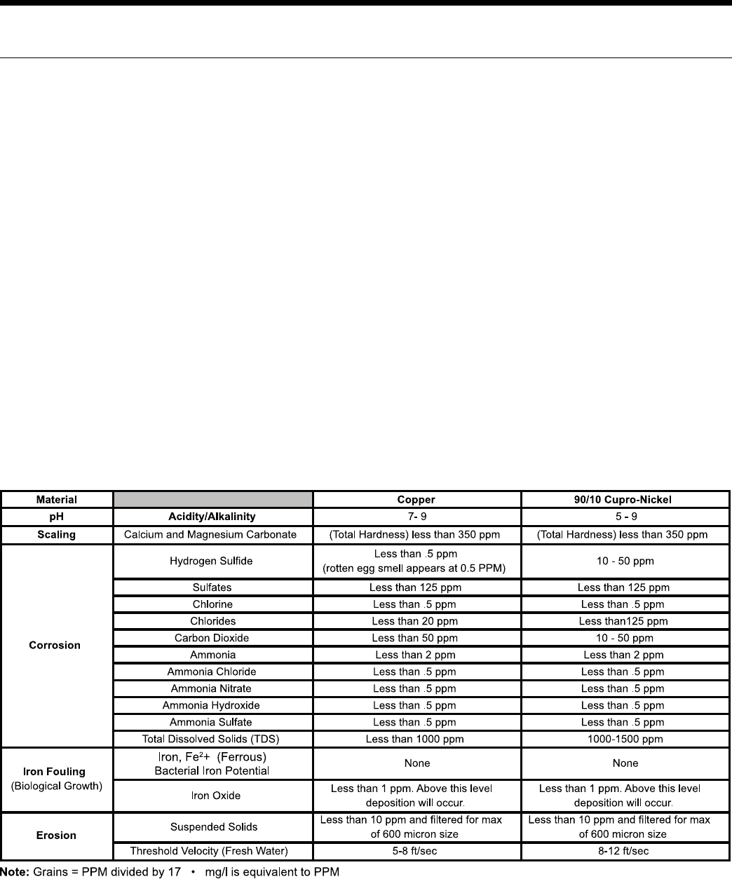
Water Quality
In ground water situations where scaling could be heavy or where biological growth such as iron bacteria will be present,
a closed loop system is recommended. The heat exchanger coils in ground water systems may, over a period of time, lose
heat exchange capabilities due to a buildup of mineral deposits inside. These can be cleaned, but only by a qualified service
mechanic, as special solutions and pumping equipment are required. Desuperheater coils can likewise become scaled and
possibly plugged. In areas with extremely hard water, the owner should be informed that the heat exchanger may require
occasional flushing.
Units with cupronickel heat exchangers are recommended for open loop applications due to the increased resistance to
build-up and corrosion, along with reduced wear caused by acid cleaning.
18
ENVISION CONSOLE INSTALLATION MANUAL
Electrical Connections
General
Be sure the available power is the same voltage and phase as that shown on the unit serial plate. Line and low voltage wir-
ing must be done in accordance with local codes or the National Electric Code, whichever is applicable.
208 Volt Operation
All Envision Series 208/230 units are factory wired for 230 volt operation. For 208 volt operation, the red and blue trans-
former wires must be switched.
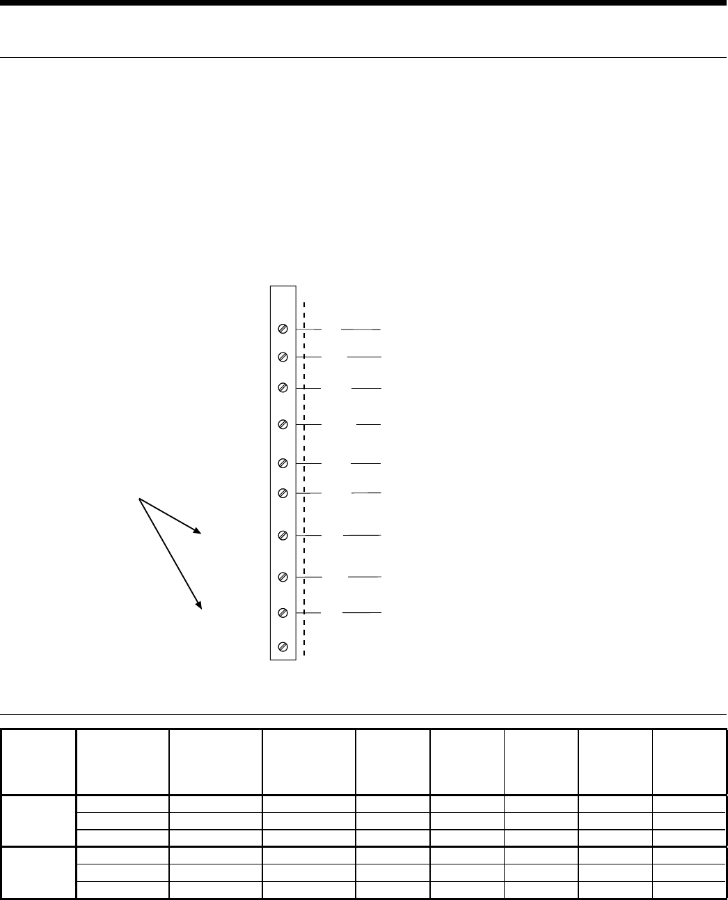
Microprocessor Remote Thermostat Wiring
Auxiliary Heat Ratings
TB
O
G
Y
C
R
L
S
X2
X1
W2
Field
Connections
Unit
Connections
24 VAC
COMMON
COMPRESSOR
REVERSING
VALVE
FAN
LOCKOUT
SIGNAL
SHUTDOWN
NIGHT
SETBACK
LOAD SHED
Requires common
connections or 24
VAC for activation
Red
Black
Yellow
Orange
Green
Brown
Blue
Violet
Pink
Figure 5
Model Rated
Voltage
Voltage
Min./Max.
Heater
Element
Watts
Fan
Motor
FLA
Heater
Element
FLA
Total
Unit
FLA
Min.
Circuit
Amp.
Max.
Fuse/
Brkr.
09-12
208/60/1 197/254 2000 0.50 9.62 10.1 12.7 15
230/60/1 197/254 2445 0.50 10.63 11.1 13.9 15
265/60/1 239/292 2000 0.55 7.55 8.1 10.1 15
15-18
208/60/1 197/254 3000 0.69 14.42 15.1 18.9 20
230/60/1 197/254 3668 0.69 15.95 16.6 20.8 25
265/60/1 239/292 3000 0.65 11.32 12.0 15.0 15
3/4/08
Always refer to unit name plate data prior to installation.
19
ENVISION CONSOLE INSTALLATION MANUAL
Fan Performance Data
Model
CFM
Low Speed High Speed
09 300 350
12 300 350
15 450 500
18 450 500
Factory settings are in Bold
Air ow values are with dry coil and standard lter.
For wet coil performance rst calculate the face velocity of the air coil
(Face Velocity [fpm] = Airow [cfm] / Face Area [sq ft]). Then for
velocities of 200 fpm reduce the static capability by 0.03 in. wg, 300
fpm by 0.08 in. wg, 400 fpm by 0.12in. wg. and 500 fpm by 0.16 in. wg.
Unit Electrical Data
Model Rated
Voltage
Voltage
Min/Max
Compressor Fan
Motor
FLA
Total
Unit
FLA
Min
Circ
Amp
Max
Fuse/
HACR
MCC RLA LRA
09 208-230/60/1 197/253 6.4 4.1 21.0 0.50 4.6 5.6 10
265/60/1* 238/292 na 4.3 22.0 0.50 4.8 5.9 10
12 208-230/60/1 197/253 7.7 4.9 25.0 0.50 5.4 6.7 10
265/60/1* 238/292 na 5.3 22.0 0.50 5.8 7.1 10
15 208-230/60/1 197/253 9.2 5.9 29.0 0.69 6.6 8.1 10
265/60/1* 238/292 na 5.6 28.0 0.65 6.3 7.7 10
18 208-230/60/1 197/253 10.4 6.7 33.5 0.69 7.3 9.0 15
265/60/1* 238/292 na 7.3 28.0 0.65 8.0 9.8 15
HACR circuit breaker in USA only
* RLA determine per UL1995 test procedure and not from compressor rating.
4/8/08
20
ENVISION CONSOLE INSTALLATION MANUAL
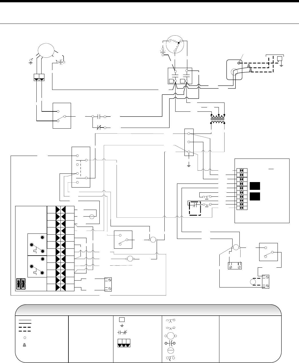
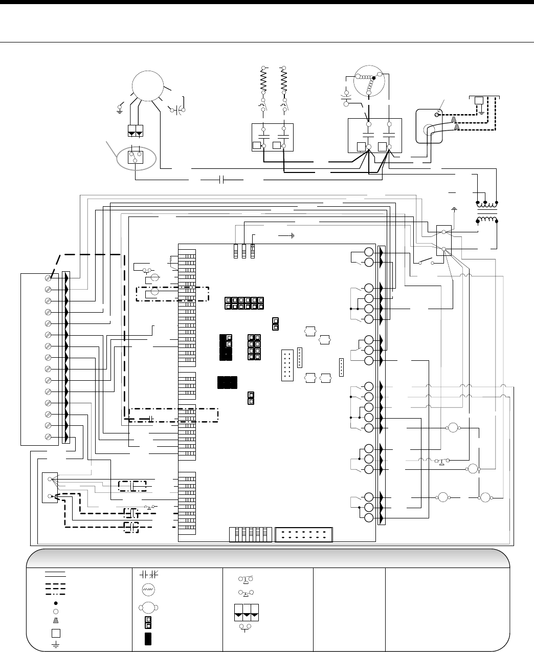
Wiring Schematic
CCM - ELECTRONIC THERMOSTAT 208-230-265/60/1
CC
CCM – with Electronic Stat
Cap
Brn
Wht
Grn
PSC
Fan
Motor
Factory low voltage wiring
Temperature Switch
Factory line voltage wiring
Quick connect terminal
Wire nut
Notes:
1. Switch Red and Blue wires for 208 volt
operation
Field low voltage wiring
Field line voltage wiring
LP
HP
Handi - Box
Ground
Lug
HL
Cycled
Continuous
CC
T2 T1
Compressor
C
R
S
Tan (33)
Red Blk
Blue
L1
L2
High
Low
Auto
Fan
6
1
3
2
4
5
COMPRESSOR
CONTROL MODULE
TEST
PIN
HP H P CC CG L O R CLP LPY
HP H P CC CG L O R CLP LPY
Transformer
24V
Blue
230V
265V
Red
208V
Black
Yellow Black/White
Black/White (1)
Red (2)
Brown (3)
Black (6)
Black (7)
Blue (8)
Blue (9)
Ther
mistor
Electronic THERMOSTAT
T1
T3
B Cool
A Heat
T2
T4
T6
T5
SHUT
DOWN
24 V
AC
IN
PUT
T6
T4
T5
T2
T1
T3
Overide
Shut down
J1
Black
Violet (5)
Violet (4)
Yellow (13)
Yellow (10)
White (20)
Orange (14) Orange (21)
Black (29)
Red (30)
Black
Black (12)
White (18)
Red (11)
Red (19)
Red (17)
24 V A ccess or y
24 V A C
S hu td ow n
Red (15)
Red (16)
NOTE 1
T
ST
CC - Compressor Contactor
HP - High Pressure Switch
LP - Low Pressure Switch
RV - Reversing Valve Coil
ST - Entering Air Temperature Sensor
RB - Blower Relay
Black
Black
Red (11)
Black (12)
Red (17)
Red (19)
Black (25)
White (28)
Black (31)
Red (32)
Brown (26)
RB
42
5
Red
RV
DT
ON
OFF
Damper Sw
Damper
Motor
D
Fan Mode Sw
Blk/Wht (24)
Blk/Wht (23)
Black (22)
White (18 )
Blue (T6)
NOTE 2
2. Terminal C of 24 V PB is used as “L”
output for Brown wire 3 for Lockout.
31
RB Violet (4)
Blue/Wht (36) Blue/Wht (35)
White (34)
Green (00)
FS
Yellow (13)
Not Used
Violet (5)
Yellow (13)
Yellow (10)
Legend
Console Unit – Wiring Schematic 208-230-265/60/1
6/10/08
Black (22)
White (28)
Black (27)
Brown (26)
DT - Damper Terminal Block
PB - Power Block
PB
1
2
3
Field wire lug
Earth Ground
Relay Contacts -
N.O., N.C.
Polarized connector
1
3
2
P
Switch - High Pressure
Switch - Low Pressure
Relay coil
Capacitor
Thermistor
HP
LP
T
L1
NOTE 3
3. Optional field installed freeze sensing
device.
FS - Freeze Sensing Device
G
Unit
Power Supply
208-230/60/1 or
265-277/60/1
21
ENVISION CONSOLE INSTALLATION MANUAL
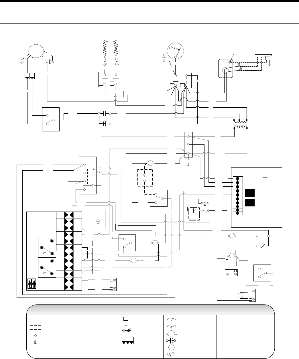
CCM w/EH - ELECTRONIC THERMOSTAT
Wiring Schematic
208-230-265/60/1
CCM – with Electric Heat and Electronic Stat
Console Unit – Wiring Schematic 208-230-265/60/1
24V
Transformer
EH
CC
Cap
Brn
Wht
Grn
PSC
Fan
Motor
Legend
LP
HP
Unit
Power Supply
208-230/60/1 or
265-277/60/1
G
Handi - Box
Ground
Lug
HL
Cycled
Continuous
CC
T2 T1
Compressor
C
R
S
Tan (33)
Red Blk
Blue
L1
L2
High
Low
Auto
Fan
6
1
3
2
4
5
COMPRESSOR
CONTROL MODULE
TEST
PIN
HP HP CC C G LO R CL P L PY
HP HP CC C G LO R CL P L PY
Blue
230V
265V
Red
208V
Black
Yellow
Black/White
Black/White (1)
Red (2)
Black (6)
Black (7)
Blue (8)
Blue (9)
Ther
mistor
Electronic THERMOSTAT
T1
T3
B Cool
A Heat
T2
T4
T6
T5
SHUT
DOWN
24 V
AC
IN
PUT
T6
T4
T5
T2
T1
T3
Overide
Shut down
J1
Black
Violet (5)
Yellow (13)
Yellow (10)
White (20)
Orange (14) Orange (21)
Black (29)
Red (30)
PB
A
C
D
Black
Black (12)
White (18)
Red (11)
Red (19)
Red (17)
24 V A c cessory
24 V A C
S hu td ow n
Red (15)
Red (16)
NOTE 1
T
ST
Black
Black
Red (11)
Black (12)
Red
(17)
Red (19)
Black (25)
White (28)
Black (31)
Red (32 )
Brown (26)
Black (27)
RB
42
5
Red
EH
T2 T1
L2
White
White
L1
EH
Normal
RV
DT
ON
OFF
Damper Sw
Damper
Motor
D
Fan Mode Sw 4
5
2
E1
E1
AQ
Blk/Wht (24)
Blk/Wht (23)
Black (22)
White (18)
Blue (T6)
NOTE 2
31
RB
3
1
Black (37)
Blue (38)
Blue/Wht (36) Blue/Wht (35)
White (34)
Blue (T6)
FS
Yellow (44)
Yellow (44)
Brown (43)
Yellow (13)
Blue
Tan (41)Blue (40)
White (28)
Blue (40)
Brown (3)
Tan (41)
Brown (26)
Green (00)
Red (39)
Gray (42)
NOTE 3
NOTE 4
Violet (4)
Violet (4)
Violet (5)
Factory low voltage wiring
Temperature Switch
Factory line voltage wiring
Quick connect terminal
Wire nut
Notes:
1. Switch Red and Blue wires for 208 volt
operation
Field low voltage wiring
Field line voltage wiring
CC - Compressor Contactor
HP - High Pressure Switch
LP - Low Pressure Switch
RV - Reversing Valve Coil
ST - Entering Air Temperature Sensor
RB - Blower Relay
2. Terminal C of 24 V PB is used as “L”
output for Brown wire 3 for Lockout.
Legend
DT - Damper Terminal Block
PB - Power Block
Field wire lug
Earth Ground
Relay Contacts -
N.O., N.C.
Polarized connector
1
3
2
P
Switch - High Pressure
Switch - Low Pressure
Relay coil
Capacitor
Thermistor
HP
LP
T
L1
3. Optional field installed freeze sensing
device.
FS - Freeze Sensing Device
4. Optional field installed aquastat.
AQ - Aquastat
EH - Electric Heat Contactor
E1 - Electric Heat Relay
6/10/08
22
ENVISION CONSOLE INSTALLATION MANUAL
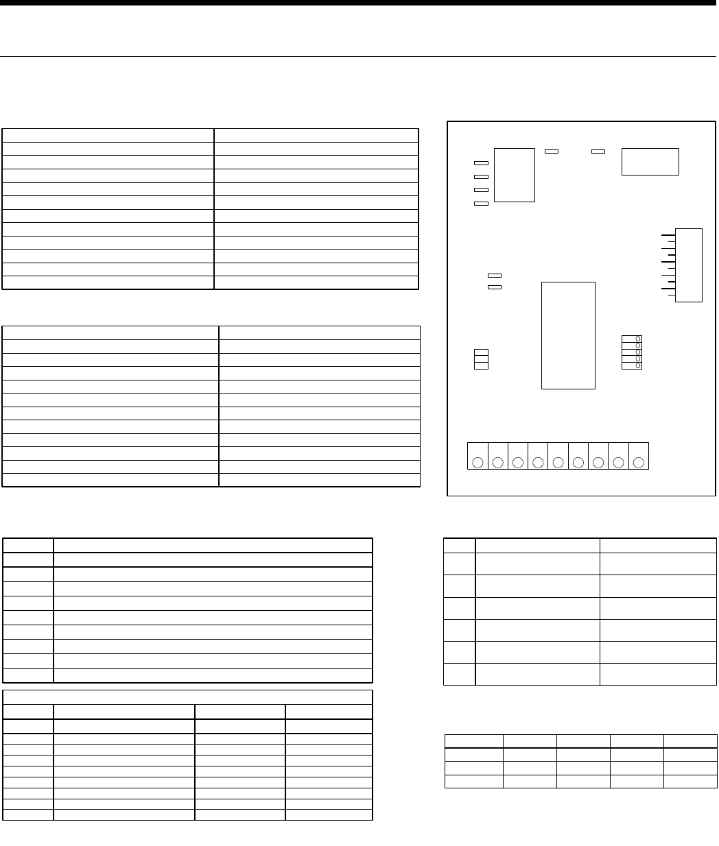
Operational Logic Table
Mode
Htg
Clg
Inputs Fan Comp RV
Y
Y,O
Fan G ON
ON
ON
OFF
ON
ON
OFF
ON
OFF
SW1 - #4 On, SW2 Off
Drain pan overflow lockout
FS thermistor (loop <15°F, well < 30°F) lockout
High pressure >600 PSI lockout
Low pressure < 40 PSI lockout
Not used
Microprocessor malfunction*
Not Used
SW2 status (Off = down position,On = up position)
Drain
Water Flow
High Press
Low Press
Air Flow
Status
DHW Limit
HWD
LED Normal Display Mode
SW1- #4 On, SW2 On
Drain pan overflow
FS thermistor (loop <15°F, well <30°F)
High pressure > 600 PSI
Low pressure < 40 PSI
Not used
Not used
Not used
SW2 in the On position
Current Fault Status
SW1- #4 Off, SW2 Off
Y
G
O
ES
NS
LS
Not Used
Off position
Inputs
Compressor
FAN
O
ES
NS
LS
Not Used
On position
Outputs
Diagnostic Modes
SW1- # 4 Off, SW2 On
Drain
Water Flow
High Press
Low Press
Air Flow
Status
DHW Limit
HWD
LED
LED Display Mode Table
CC Relay
Fan Relay
CC
CCG
C
C
R
R
FAN FANCOM
R C Y O G LO ES NS LS
P3
P1
SW1
Microprocessor
Logic Control
17P529A01
P2
61
72
83
94
10 5
Versatec Logic Board Physical Layout
Switch OFF ON
SW1 - 1
SW1 - 2
SW1 - 3
SW1 - 4
SW1 - 5
SW2
Test - Selected timings sped up to facilitate
troubleshooting
Loop - Closed loop freeze sensing setting (15°F)
IO Display * - Enables Input/Output display on external
LED board*
Enables NS features
Motorized Valve - 1.5 minute compressor on delay
OFF * - Normal or Input display mode activated ON * - Current fault or Output display
mode activated
Normal - Standard timings
Well - Open loop freeze sensing setting (30°F)
Normal * - Unit status display
Normal - Standard thermostat operation
Normal - Standard delay on call from
compressor used
*Refer to LED Display Mode table for position of SW1-4 and SW2
Logic Board DIP Switch Settings
Normal Control Timing Table
Blower off delay
Compressor on delay
Short cycle delay
Minimum compressor on time
High pressure fault recognition delay
Low pressure fault recognition delay
Condensate overflow fault recognition delay
Low pressure fault bypass delay
Freeze sensing fault bypass delay
Motorized valve delay
Random start delay
Freeze sensing fault recognition delay
30 seconds
10 seconds
5 minutes
60 seconds (except for fault condition )
Less than 1 second
30 seconds
30 seconds
30 seconds
2 minutes
2 minutes
90 seconds
0 - 25 seconds
Test Control Timing Table
Blower off delay
Compressor on delay
Short cycle delay
Minimum compressor on time
High pressure fault recognition delay
Low pressure fault recognition delay
Condensate overflow fault recognition delay
Low pressure fault bypass delay
Freeze sensing fault bypass delay
Motorized valve delay
Random start delay
Freeze sensing fault recognition delay
5 seconds
2 seconds
15 seconds
5 seconds (except for fault condition )
Less than 1 second
30 seconds
30 seconds
30 seconds
0 seconds
0 seconds
90 seconds
0 seconds
*Flashing Status light indicates microprocessor is functioning properly. Solid "on" indicates a
microprocessor malfunction.
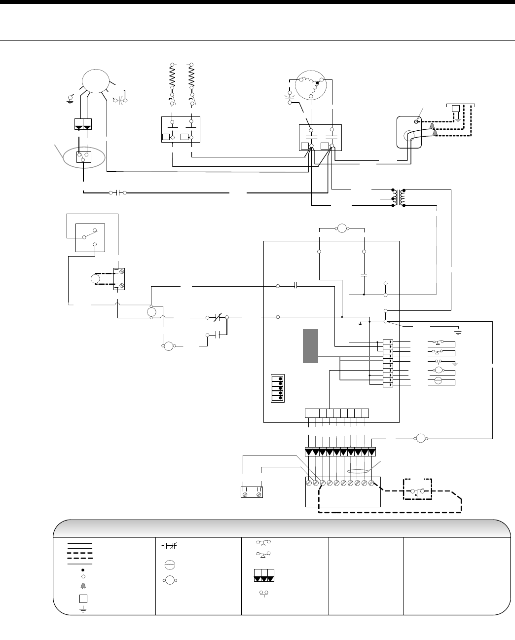
Wiring Schematic
208-230-265/60/1VERSATEC CONTROL - EH & REMOTE WALL THERMOSTAT
Legend for Schematic [A]
23
ENVISION CONSOLE INSTALLATION MANUAL
Wiring Schematic
208-230-265/60/1VERSATEC CONTROL - EH & REMOTE WALL THERMOSTAT
Schematic [A]
Transformer
24V
Cap
Brn/Wht
Brn
Grn
H L
PSC
Fan
Motor
CC
T2 T1
Compressor
C
R
S
Tan (36)
Red
Blu
L1L2
Relay Contacts-
N.O., N.C.
Thermistor
Relay coil
Switch - High pressure
Switch - Low pressure
Polarized connector
Condensate Overflow
Factory low voltage wiring
Factory line voltage wiring
Field low voltage wiring
Field line voltage wiring
Internal junction
Quick connect terminal
Wire nut
Field wire lug
Ground
L1
Legend
5 - Switch blue and red wires for 208V operation.
T
1
3
2
P
Notes:
1 - Requires common connection or 24 VAC for
activation.
NOTE 5
Red 208V
Blue 230V
Blk
Black(27)
R
C
C
R
CC
CCG
OnOff
Test / Normal
Loop / Well
P2
P1
SW1
Inputs / Normal
Outputs / Normal
1
2
3
4
5Motorized Valve / Normal
FAN
FAN
COM
CPU
FS
LP
HP
RV
CO
LSNSESLOGOYCR
Yellow
Black/White
T
Black (47)1
6
2
7
3
8
4
9
5
10
DC voltage PCB traces
High Low
Fan Speed
Switch
RB
Blue 265V
4 - Check installlation wiring information for
specific thermostat hookup instructions.
Red
Black (25)
RB
Gray (42)
White (28)
Black(29)
Red (30)
Damper
Motor
Off
On
DAMPER MODE
DT
D
Blue/Wht (35)
MV
Black (31)
Red (32)
Handi - Box
Ground
Lug
Unit
Power Supply
208-230/60/1 or
265-277/60/1
G
CR Y1 O G L S
Terminal Board
X2 X1 W1
Red
Bl ack
Yellow
Orange
Brown
Green
NOTE 2
Violet
Pink
Bl ue
1 3
4 2
NOTE 1
ES – Emergency Shutdown
Black/
White
Black/
White
Black Com
E1
EH
T2 T1
L1
White
White
L2
Blue (40)
LS1
LS2
Black
Tan (41)
E1
4
2
5
Black (37)
Blue (38)
Red (39)
AQ
NOTE 3
White
2 - When field installed 24VAC motorized
valve is used, connect to C and Y or SV terminals.
3 - Optional field installed aquastat for use with single heat
Blue/Wht (36)
Black (46)
Blue (45)
Blue (44)
Brown(43)
Orange (42)
Orange (41 )
Yellow
Yellow
Green (00)
Black (22) Orange (21)
EH
CC
White (34)
Brown (43)
Legend
Microprocessor – with Remote Wall Stat & Electric Heat
Console Unit – Wiring Schematic 208-230-265/60/1
97P786-04 6/10/08
EH – Electric Heat Contactor
AQ – Aquastat
CC – Compressor Contactor
CO – Condensate Overflow
E1 – Electric Heat Relay
FS – Freeze Sensing Device
HP – High Pressure Switch
LP – Low Pressure Switch
LS – Loadshed
NS – Night Setback
RB – Blower Power Relay
RV – Reversing Valve Coil
SW1 – DIP Switch #1
MV – Motorized Valve
Red(19)
DT – Damper Terminal Block
24
ENVISION CONSOLE INSTALLATION MANUAL
Wiring Schematic
FX10 - EH 208-230-265/60/1
Transformer
Blue 240V
Red 208V
Black
Blk/Wht
Black
DA T
HP
RB
RV
CC
NOTE 1
277V
FS T
CO
Yellow
PB1
L1
L2
OS
NOTE 2 CP/FP
DF/AP
L1
L2
PB2
NOTE 3
NOTE 4
NOTE 5
Compressor
CC
T2
R
S
C
BlkRed
Tan
Blu
L2
T1
L1
Handi - Box
Ground
Lug
Unit
Power Supply
208-230/60/1 or
265-277/60/1
G
Black
Red
Cap
Brn/Wht
Brn
Grn
H L
PSC
Fan
Motor
High Low
Fan Speed
Switch
RB
ES
LP
11 K
Johnson FX-10
5VDC
AI3
23
24
25
26
27
28
29
30
31
32
33
34
35
36
37
38
+
-
AI5
-
+
AI4
-
+
AI6
AI2
AI1
5VDC
5VDC
LED
-
-
-
+
+
+
24VAC
24VAC Com
GROUND
39
40
41
PWM2
PWM2 Com
PWM1
42
43
44
45
46
47
48
24VAC Com
DI12
DI11
DI10
DI9
DI8
DI7
49
50
51
52
53
54
55
56
DI 3/4 /5/6/ Com
DI6
DI5
DI4
DI3
DI2
DI1
9VDC
20
19
18
17
16
15
14
13
12
11
10
9
8
7
6
5
4
3
1
D09
D08
D07
D06
D05
D04
D03
D02
D01
J8
J2
J10
J9
J7
A32
A31A35
A14
A24
A34
A33
A15
TThermistor - Johnson Control
Relay coil
Switch - High pressure
Switch - Low pressure
Polarized connector
Condensate Overflow
1
3
2
P
Factory low voltage wiring
Factory line voltage wiring
Field low voltage wiring
Field line voltage wiring
Internal junction
Quick connect terminal
Wire nut
Field wire lug
Ground
Notes:
L1
1 - Switch Blue and Red wires for 208V operation
Relay Contacts-
N.O., N.C.
2 - Disconnect for 15 degree freeze protection
Field Zone Sensor Wiring 3 - Acc 1 output is cycled with the compressor.
4 - Acc 2 output is cycled with the fan.
5 - R, C, Y1, O, and G inputs are for use with a wall mounted
thermostat.
A23
A13
A11
A21A12
A25 A22
Open Jumper
Closed Jumper
2
TB
R
C
Y1
O
G
L
X1
X2
24VAC
24V COM
Alarm
Acc 1
Acc 2
Fan
Rev Valve
Comp
SS
AIC
RS
SC
TO
Setpoint Shift
AI Com
Room Sensor
Sensor Com
Temp Occ
EHC
T2 T1
L1
L2
Blue
White White
LS1 LS2
Black (6)
Blue (4)
MEHS
EHC
Molex
Plug
White
Black
Blk/Red (9)
White (5)
Wht/Blu (6)
Brown (2)
Black (22)
Blk/Wht (29)
Blue (27)Blue (32)
Yellow (35) Blk/Wht (36)
Black (6)
Black (6)
Yellow (33)
Black (34)
Black(121) Black (515) Black (131)
Brown (1)
Gry/Wht (14)
Orange (30)
Pink (28 )
Red (24 )
Violet (23)
Black (31)
Green (37)
Yellow
Yellow (16)
Red (20)
Black (1)
Black (2 )
Orange (7)
Black
(12)
Gray (3)
Black (5)
Yellow (9)
Black (310)
Black (111)
Blk Red
LC1
LC2
Molex
Plug
TAN
BLUE
Blk
Blk
Blk/Wht
Orange
White
Black (310)
Black (111)
Gray (26)
Org/Wht (12)
Org/Bck (11)
Blu/Wht (10)
Yellow (21)
Orange (19)
Green (17)
Red (120)
Red (120)
FX10 – with Electric Heat
Console Unit – Wiring Schematic 208-230-265/60/1 97PXXX -XX
Legend
CC - Compressor Contactor
CO - Condensate Overflow
CP/FP - Compressor Proving/Fan Proving
DA - Discharge Air Temperature
DF/AP - Dirty Filter/Air Proving
EHC - Electric Heat Contactor
EHR - Electric Heat Relay
ES - Emergency Shutdown
FS - Freeze Sensing Device
HP - High Pressure Switch
LP - Low Pressure Switch
MEHS - Manual EH Switch
OS - Occupied Switch
RB - Blower Power Replay
RV - Reversing Valve Coil
TB - Terminal Block
6/10/08
25
ENVISION CONSOLE INSTALLATION MANUAL
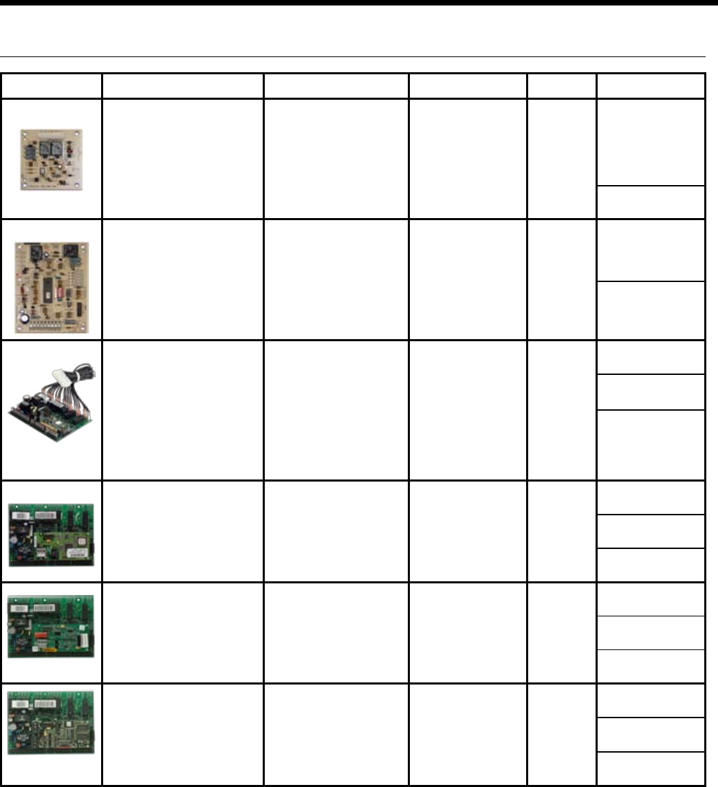
Control General Description Application Display/Interface Protocol Thermostat Options
CCM Control The CCM (Compressor control module)
is a more reliable replacement for
electro-mechanical control applications.
It features a small microprocessor
board that handles the lockout function
of the unit. A second microporcessor
handles the unit mounted thermostat for
maintaining accurate room temperature.
Residential and commercial
applications requiring minimal but
reliable controls. Includes Random
Start, High and low pressure
switches and auto changeover
capability.
Dial thermostat with Hi and
Low fan speeds, and auto
changeover or cont fan
selection switches.
None Unit Mounted Digital
Dial Thermostat
Remote Mounted
Standard Thermostat
Versatec Control The Versatec Control is a
microprocessor based board that adds
the features of emergency shutdown
(ES), night setback (NS), water freeze
sensing (FS), Load Shed (LS) and
condensate overow (CO). The
Versatec Control also features Optional
Field servicing LED's for mode, Fault
and diagnostic indication.
Residential and commercial
applications requiring more controls
features than CCM and Includes
Random Start, High and low
pressure switches, auto changeover
capability, emergency shutdown
(ES), night setback (NS), load shed
(LS), water freeze sensing (FS), and
condensate overow (CO).
Optional eld servicing LED
board for mode, fault and
diagnostic indication
None Unit Mounted Digital
Dial Thermostat
Remote Mounted
Standard Thermostat
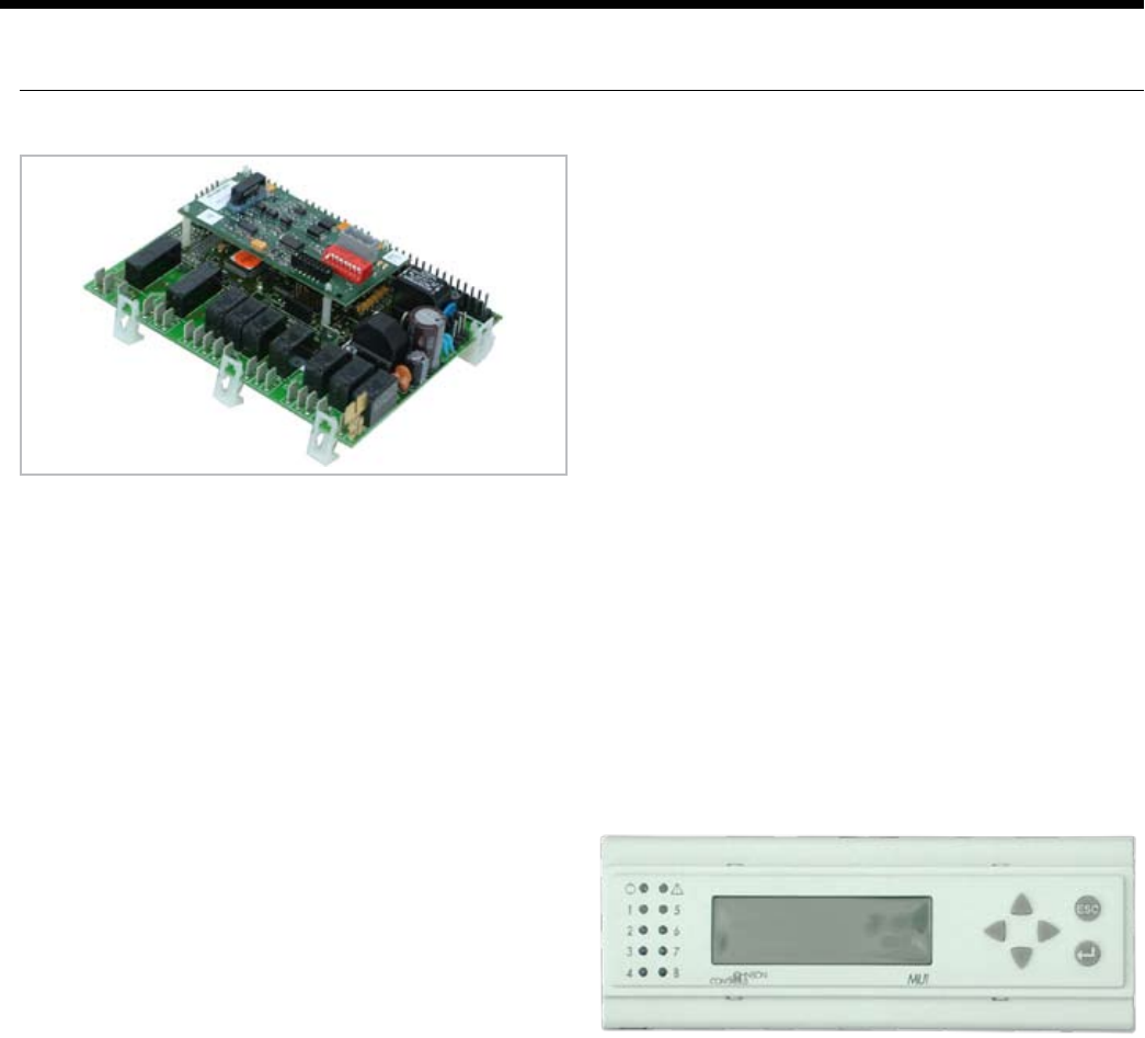
FX10 The FX10 microprocessor control is self
contained control featuring LP, LOC,
HP, LWT, and condensate overow
fault modes can be displayed on BAS
system. Optional handheld Medium User
Interface (MUI) Control can be used for
additional setup or servicing. Program
customization is possible. This control is
suited for both single and dual capacity
compressors as well as PSC and ECM
fan motors.
Commercial applications using sin-
gle and dual capacity compressors
with either PSC or ECM fan motors.
Also suitable for multi-compressor
products. Cannot be integrated
with centralized building automation
systems. Software can be custom-
ized for specic projects.
Optional Medium User
Interface (MUI) can be
used as a
eld service tool.
Standalone Unit Mounted Digital
Dial Sensor
Remote Mounted
Standard Thermostat
Remote Mounted
Sensor
FX10 w/ N2 FX10 Control functions as both unitary
heat pump control and DDC communica-
tion, therefore detail operational and
fault information is available to BAS.
Other features are same as FX10 with
addition of Johnson Controls N2 compat-
ibility.
Same as FX10 with Johnson
Controls N2 BAS compatibility.
Optional Medium User
Interface (MUI) can be
used as a
eld service tool.
Johnson
Controls
N2 network
Unit Mounted Digital
Dial Sensor
Remote Mounted
Standard Thermostat
Remote Mounted
Sensor
FX10 w/ LonWorks FX10 Control functions as both unitary
heat pump control and DDC communica-
tion, therefore detail operational and
fault information is available to BAS.
Other features are same as FX10 with
addition of LonWorks compatibility.
Same as FX10 with LonWorks BAS
compatibility.
Optional Medium User
Interface (MUI) can be
used as a
eld service tool.
LonWorks Unit Mounted Digital
Dial Sensor
Remote Mounted
Standard Thermostat
Remote Mounted
Sensor
FX10 w/ BACnet FX10 Control functions as both unitary
heat pump control and DDC communica-
tion, therefore detail operational and
fault information is available to BAS.
Other features are same as FX10 with
addition of BACnet compatibility.
Same as FX10 with BACnet BAS
compatibility.
Due to communication speed,
no more than 40 units should
be connected to a single trunk
of the network.
Optional Medium User Inter-
face (MUI) can be mounted
or used as a
eld service tool.
BACnet - MS/
TP
(19,200 Baud
Rate)
Unit Mounted Digital
Dial Sensor
Remote Mounted
Standard Thermostat
Remote Mounted
Sensor
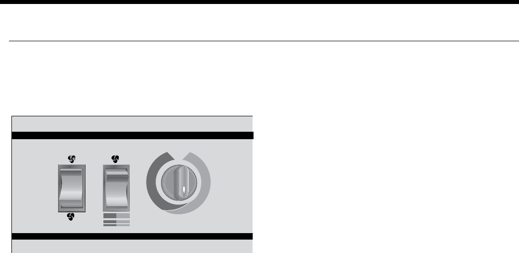
Standard CCM Control Features
Compressor control module (CCM) controls are standard
on the Envision console heat pump. This control features
unit mounted thermostat and switches,
Features of the standard control are:
Easy to understand color coded thermostat •
adjustment markings.
Large, rocker type mode and fan switches.•
Internally mounted fan switch to choose cycled or •
constant fan operation.
High pressure and low pressure safety controls to •
protect the unit components.
Lockout circuit to shut down unit operation upon •
receipt of a fault indicator from the safety controls.
A 24 volt control circuit allows for safe and •
easy diagnosis.
Envision Console Controls
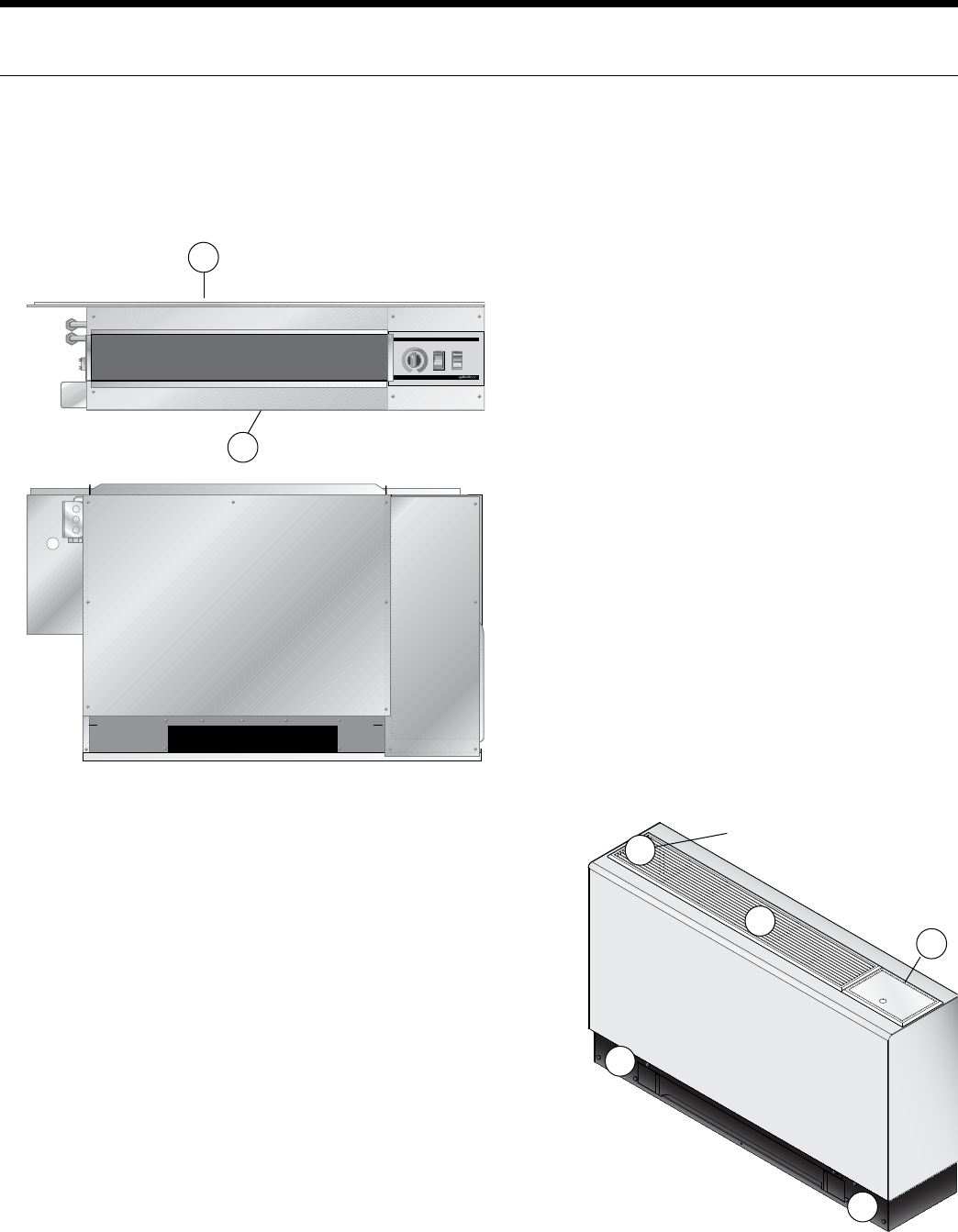
26
ENVISION CONSOLE INSTALLATION MANUAL
The user selects either “Heat/Cool” or “Fan Only” on the
mode switch, then either “High” or “Low” at the fan speed
switch. The temperature can be controlled by rotating the
thermostat control knob.
The “Fan Only” setting provides constant fan operation.
In the “Heat” mode, a call for heat by the thermostat closes
the compressor contactor contacts, energizing the com-
pressor, which will run until the thermostat is satisfied.
In the “Cool” mode, a call for cooling by the
thermostat energizes the reversing valve and closes the
compressor contactor contacts, energizing the compres-
sor, which will run until the thermostat is satisfied.
The emergency electric heat operation in the “Heat/Cool”
mode is subject to the setting of the internally mounted
mode switch. The optional, factory installed electric heat
will operate when the internally mounted mode switch is
in the “Emergency Heat” mode. In the “Heat” mode, a call
for heating energizes the fan and electric heater contactor,
energizing the electric heat elements and fan, which will
run until the thermostat is satisfied. When the internally
mounted mode switch is in the “Normal/Boilerless” mode
the unit operates in its normal “Heat/Cool” operation,
unless there is an aquastat controller. When the normally
open circuit of the aquastat closes and the unit is in the
heating mode, it will switch to the “Emergency Heat”
condition until the thermostat is satisfied or the aquastat
opens restarting the compressor.
If either the low or high pressure safety switches are
opened, the compressor and reversing valve are disabled
by the lockout relay. Unit operation will resume only after
the voltage to the unit is interrupted or the mode switch is
placed in the “Off” position.
If the electric heat limit switches are opened, the electric
heat is disabled.
Optional Versatec Microprocessor
Control Features
The Versatec microprocessor board provides control of
the entire unit as well as outputs for status modes, faults
and diagnostics. The control system is a microprocessor-
based control board that is located in the unit control box.
This feature is available for either unit mounted controls
or optional remote wall mounted thermostat. A 9-pin low
voltage terminal strip provides all necessary terminals for
the wall mounted thermostat.
Startup
The unit will not operate until all the inputs and safety
controls are checked for normal operating conditions.
Fault Retry
All faults are retried twice before finally locking the unit
out to prevent nuisance service calls.
Component Sequencing Delays
Components are sequenced and delayed for optimum unit
performance.
Short Cycle Protection and Random Start
The control allows a minimum on or off time of 5 minutes
for short cycle protection. A random time delay of 0 to
30 seconds is generated after each power-up to prevent
simultaneous start up of all units within a building after the
release from an unoccupied cycle or power loss.
Night Setback
A grounded signal to common or connecting 24 VAC to
the NS terminal will initiate the night setback mode.
Load Shed
A grounded signal to common or connecting 24 VAC to
the LS terminal places the controller into the load shed
mode. The compressor will become disabled and the fan
will start upon a thermostat call for heating or cooling.
Emergency Shutdown
A grounded signal to common or connecting 24 VAC to
the ES terminal places the controller into the emergency
shutdown mode. The compressor and fan operation are
suspended while in the emergency shutdown mode.
Condensate Overflow Protection
The board incorporates an impedance liquid sensor at the
top of the condensate drain pan. Upon a continuous 30-
second sensing of the condensate, the cooling operation of
the unit is suspended.
Safety Controls
The microprocessor board receives separate signals from
a high pressure switch for safety, a low pressure switch to
Figure 6: Unit Mounted Control
Envision Console Controls
27
ENVISION CONSOLE INSTALLATION MANUAL
Envision Console Controls
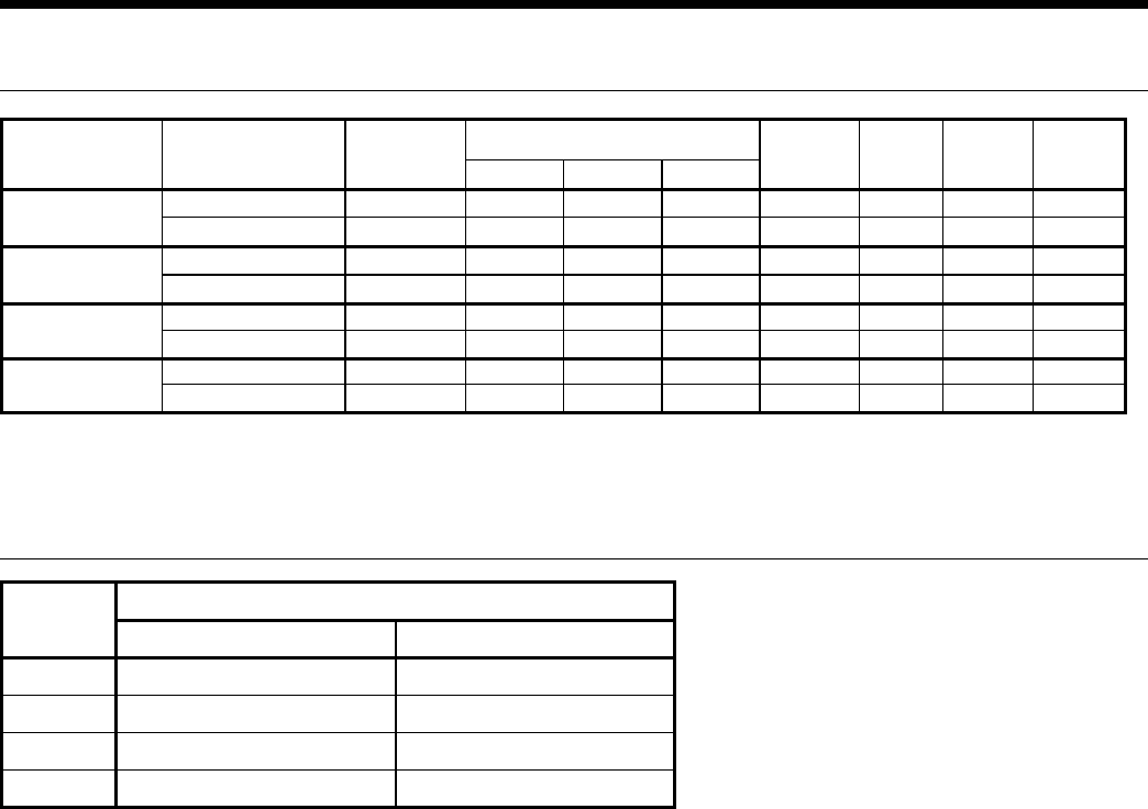
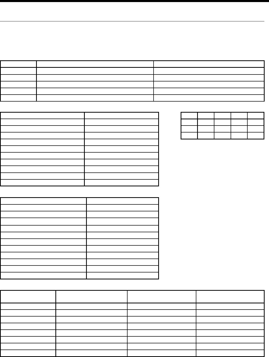
Mode Inputs Fan Comp RV
Htg Y ON ON OFF
Clg Y,O ON ON ON
Fan G ON OFF OFF
Switch OFF ON
SW1 - 1 Test - Selected timings sped up to facilitate troubleshooting Normal - Standard timings
SW1 - 2 Loop - Closed loop freeze sensing setting (15°F) Well - Open loop freeze sensing setting (30°F)
SW1 - 3 Commercial - Enables NS features when TA32U02 thermostat is used Normal - Standard thermostat operation
SW1 - 4 IO Display* - Enables Input/Output display on external LED board Normal* - Unit status display
SW1 - 5 Configures board for 2-speed compressor without fan Configures board for 2-speed compressor with fan
Logic Board DIP Switch Settings
Blower off delay 30 seconds
Compressor on delay 10 seconds
Short cycle delay 5 minutes
Miniumum compressor on time 2 minutes (except for fault condition)
High pressure fault recognition delay Less than 1 second
low pressure fault recognition delay 30 seconds
Freeze sensing fault recognition delay 30 seconds
Condensate overflow fault recognition delay 30 seconds
Low pressure fault bypass delay 2 minutes
Freeze sensing fault bypass delay 2 minutes
Power on delay 5 minutes
Normal Control Timing Operational Logic
Blower off delay 5 seconds
Compressor on delay 2 seconds
Short cycle delay 15 seconds
Miniumum compressor on time 5 seconds (except for fault condition)
High pressure fault recognition delay Less than 1 second
low pressure fault recognition delay 30 seconds
Freeze sensing fault recognition delay 30 seconds
Condensate overflow fault recognition delay 30 seconds
Low pressure fault bypass delay 0 seconds
Freeze sensing fault bypass delay 0 seconds
Power on delay 15 seconds
Fault off time 5 minutes
Test Control Timing
LED Current Fault Status
SW1 - #4 On, SW2 On
Inputs
SW1 - #4 Off, SW2 Off
Outputs
SW1 - #4 Off, SW2 On
Drain Drain pan overflow Y Compressor
Water Flow FS thermistor (loop <15°F, well <30°F) G FAN
High Press High pressure >600 PSI O O
Low Press Low pressure <40 PSI ES ES
Air Flow Not used NS NS
Status Not used LS LS
DHW Limit Not used Not used Not used
HWD SW2 in the On position Off position On position
Diagnostic Modes
prevent loss of refrigerant charge and a low suction tem-
perature thermistor for freeze sensing. Upon a continuous
30-second measurement of the fault (immediate for high
pressure), compressor operation is stopped.
Control Tables for Optional Versatec Microprocessor
28
ENVISION CONSOLE INSTALLATION MANUAL
Optional FX10 Control
The optional FX10 control provides unparalleled capability
in several areas including performance monitoring, zoning,
humidity, energy management, and service diagnosis, and
then communicates it all thru standard DDC protocols like
N2, Lon and BACnet (MS/TP @ 19,200 Baud rate).
The most unique feature is integrating the FX10 into the
Envision series as both the heat pump and DDC controller
providing both a cost advantage and providing features
not typically found on WLHP controls. This integration
allows heat pump monitoring sensors, status and service
diagnosis faults to be communicated thru the DDC direct
to the building automation system (BAS), giving building
supervisors detailed and accurate information on every
piece of equipment without removing an access panel.
FX10 Advanced Control Overview
The Johnson Controls FX10 board is specifically designed
for commercial heat pumps and provides control of the
entire unit as well as input ports for Open N2, LonTalk,
BACnet (MS/TP @ 19,200 Baud rate) communication
protocols as well as an input port for a user interface. The
user interface is an accessory item that can be used to aid
in diagnostics and unit setup. A 16-pin low voltage terminal
board provides terminals for common field connections.
The FX10 Control provides:
Operational sequencing•
High and low-pressure switch monitoring •
General lockout•
Water Coil Low Temperature (Freeze Sensing) •
Condensate overflow sensing •
Lockout mode control •
Emergency shutdown mode •
Random start and short cycle protection•
Short Cycle Protection
Allows a minimum compressor “off” time of four minutes
and a minimum “on” time of two minutes.
Random Start
A delay of 1 to 120 seconds is generated after each power-
up to prevent simultaneous startup of all units within a
building after the release from an unoccupied cycle or
power loss.
Emergency Shutdown
A field-applied dry contact can be used to place the con-
trol into emergency shutdown mode. During this mode, all
outputs on the board are disabled.
Water Coil Low Temperature (Freeze Sensing) Limit
Field selectable for 15° or 30°F (-9° or -1°C)
Installation Options
Standalone controlled by standard room thermostat•
Standalone with a Zone Temperature Sensor (must •
have user interface to change set points beyond the
allowed +/- 5°F)
Integrated into BAS by adding communication module•
Accessory Outputs
Quantity 2. One cycled with fan, other with compressor.
User Interface
4 x 20 backlit LCD.
Optional Plug-in Communication Modules -
(compatible with standard BAS protocols)
Open N2•
LonTalk•
BACnet (MS/TP @ 19,200 Baud rate)•
Display
Requires DLI Card/Kit. Up to 2 displays, either 1 local and
1 remote, or 2 remote. (A 2-display configuration requires
identical displays.) Local display can be up to 3 meters
from the controller, power supply, and data communica-
tion. Remote display can be up to 300 meters from the
controller. Remote display must be independently powered
with data communication done via 3 pole shielded cable.
Envision Console Controls
Main FX 10 Board
29
ENVISION CONSOLE INSTALLATION MANUAL
Control Timing & Fault Recognition Delays
Lead compressor “ON” delay ..........................................90 seconds
(not applicable for single compressor models)
Minimum compressor “ON” time ...................................... 2 minutes
(except for fault condition)
Short cycle delay ..................................................................... 5 minutes
Random start delay .......................................................0-120 seconds
High pressure fault ................................................................. <1 second
Low pressure fault ...............................................................30 seconds
Water coil low temperature (freeze sensing) fault .......30 seconds
Condensate overflow fault ...............................................30 seconds
Low pressure fault bypass ................................................... 2 minutes
Water coil low temperature (freeze sensing)
fault bypass .......................................................................... 2 minutes
Notes: Refer to Submittal Data SD1981, Application
Guide AGFX10, or BACnet Protocol Implementation
Conformance Statement for more information.
Optional FX10 Microprocessor
and BAS Interface
The FX10 is a microprocessor based control that not only
monitors and controls the heat pump but also can com-
municate any of this information back to the building
automation system (BAS). This means that not only does
the control monitor the heat pump at the unit you can also
monitor and control many the features over the BAS. This
clearly puts the FX10 in a class of its own.
The control will enumerate all fault conditions (HP, LP, CO,
LOC, and Water Coil Low Temp (Freeze Sensing)) over a
BAS as well as display them on a medium user interface
(MUI). HP, LP, CO and Water Coil Low Temp (Freeze Sens-
ing) faults can all be reset over a BAS. A Loss Of Charge
fault can not be reset or bypassed until the problem has
been corrected. A MUI is invaluable as a service tool for the
building service team.
The unit can be commanded to run by a typical heat
pump thermostat or run based on heating and cooling
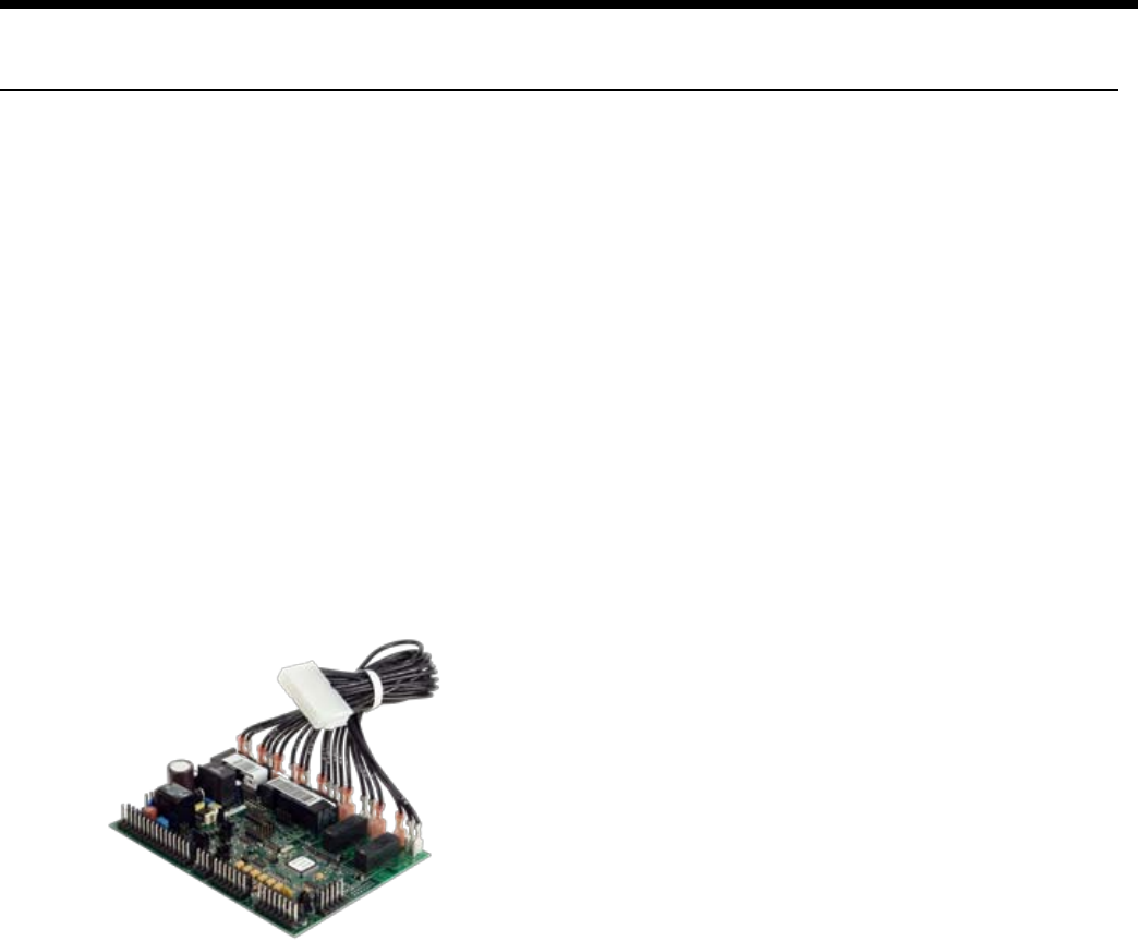
set points supplied by a BAS. The control board is wired
with quick connect harnesses for easy field change out of
a bad control board. All ECM variable fan speed settings
can be changed over a BAS or with a MUI. The control has
an input programmed to enable field installed emergency
heat in the event that the compressor is locked out. This
input can also be commanded on from a BAS as needed.
An alarm history can be viewed through the MUI and will
be held in memory until the unit is power cycled. Relative
humidity can be read by a 0-5VDC humidity sensor that
is displayed over the network. If you are using an ECM
fan motor the control can enable dehumidification mode
based on a set point in the control. The dehumidification
set point itself can also be changed over a BAS or with a
MUI. Dehumidification mode can also be enabled by the
BAS. Because the FX10 is not factory configured to read
CO2 levels, contact the factory for application assistance.
The FX10 control has unused analog and digital inputs for
field installed items such as air temperature, water tem-
perature, CO2 or current status switches. The control has
unused binary and PWM outputs that can be commanded
over the BAS for field use. An optional Medium User Inter-
face (MUI) for control setup and advanced diagnostics is
available with some mounting kits, MUIK1 - Panel mount
version and the MUIK2-Wall mount version.
Zone Sensors
There are two options for zone sensors that can be used
with the FX10 control. Both sensors use a Johnson con-
trols A99 positive temperature coefficient type sensor.
The TAXXJ02 has a set point adjustment now which will
give the end user a +/- 5°F adjustment from the set point
as well as a push button that can be used for temporary
occupancy. The control leaves the factory set to operate
with a TAXXJ02 sensor and can be changed to read the
TAXXA01 sensor through a building automation system or
with a user interface.
Standard Features
Anti Short Cycle•
High Pressure Protection•
Low Pressure Protection•
Water Coil Low Temperature (Freeze Sensing)•
Loss Of Charge Detection•
Random Start•
Display for diagnostics•
Reset Lockout at disconnect or through BAS•
2 Accessory outputs•
Optional BAS add-on controls•
DDC Operation & Connection
Other optional network protocol boards that can be added
to the FX10 are:
Johnson Control N2•
LonWorks•
BACnet •
Envision Console Controls

30
ENVISION CONSOLE INSTALLATION MANUAL
- MS/TP @ 19,200 Baud rate
- Limit devices to 40 on a single trunk line.
Control and Safety Feature Details
Emergency Shutdown
The emergency shutdown mode can be activated by a
command from a facility management system or a closed
contact on BI-2. The default state for the emergency shut-
down data point is off. When the emergency shutdown
mode is activated, all outputs will be turned off immediate-
ly and will remain off until the emergency shutdown mode
is de-activated. The first time the compressor starts after
the emergency shutdown mode has been de-activated,
there will be a random start delay present.
Lockout Mode
Lockout mode can be activated by any of the following
fault signals: refrigerant system high pressure, refrigerant
system low pressure, water coil low temperature (freeze
sensing), and condensate overflow. When any valid fault
signal remains continuously active for the length of its rec-
ognition delay, the controller will go into fault retry mode,
which will turn off the compressor. After the Compressor
short cycle delay, the compressor will attempt to operate
once again. If three consecutive faults occur in 60 minutes
during a single heating or cooling demand, the unit will go
into lockout mode, turning off the compressor, enabling
the alarm output, and setting the fan back to low speed
operation until the controller is reset. If the control faults
due to the low pressure input (BI-3) being open during
the pre-compressor startup check, the control will go into
lockout mode immediately, disabling the compressor from
starting and enabling the alarm output (BO-6). The lockout
condition can be reset by powering down the controller, by
a command from the BAS, or by the holding the ESC and
Return keys on the MUI for 5 seconds.
Water Coil Low Temp (Freeze Sensing) Limit (AI-5)
The water coil low temperature (freeze sensing) limit sen-
sor will monitor the liquid refrigerant temperature enter-
ing the water coil in the heating mode. If the temperature
drops below the water coil low temperature (freeze sens-
ing) limit trip point for the recognition delay period, the
condition will be recognized as a fault. The water coil low
temperature (freeze sensing) limit trip point will be factory
set for 30°F and will be field selectable for 15°F by remov-
ing a jumper wire on BI-5. The water coil low temperature
(freeze sensing) limit fault condition will be bypassed 2
minutes at normal compressor startup, to allow the refrig-
eration circuit to stabilize. If the water coil low temperature
(freeze sensing) limit sensor becomes unreliable at any
time compressor operation will immediately be suspended
until the problem is corrected. This should be displayed
as an alarm on the BAS and the MUI. This alarm will be
reported a “Water Low Temp Limit” fault.
High Pressure (BI-11)
The high-pressure switch shall be a normally closed (NC)
switch that monitors the systems refrigerant pressure. If
the input senses the high-pressure switch is open it must
disable the compressor output immediately and count the
fault. The compressor minimum on time does not apply if
the high-pressure switch opens. The compressor will not
restart until the compressor short cycle time delay has
been satisfied.
Low Pressure (BI-3)
The low-pressure switch shall be a normally closed (NC)
switch that monitors the systems refrigerant pressure. The
input shall be checked 15 seconds before compressor start
up to be sure the pressure switch is closed and then ignored
for the first 2 minutes after the compressor output (BO-2) is
enabled. If the switch is open continuously for (30) seconds
during compressor operation the compressor output (BO-2)
will be disabled. The compressor will not restart until the
compressor short cycle time delay has been satisfied.
Condensate Overflow
The condensate overflow sensing circuit will monitor the
condensate level as a resistance input to AI-3. If the con-
densate water level rises resulting in the input resistance
rising above the set point for the recognition delay period,
the condition will be recognized as a fault. The condensate
will be subjected to a (30) second lockout delay which
requires that the fault be sensed for a continuous (30)
seconds before suspending unit operation.
Alarm Output (BO-6)
The alarm output will be enabled when the control is in the
lockout mode and will be disabled when the lockout is reset.
Test Mode
Raising the zone temperature input (AI-1) reading to
180–220°F or by holding the ESC and down arrow keys on
the MUI for 5 seconds will put the control into test mode.
In test mode the random start delay and the compressor
fixed on delay time will both be shortened to 5 seconds
and the reversing valve will be allowed to cycle with out
shutting down the compressor. If an MUI is connected to
the control LED 8 will flash and the words “Test Mode En-
abled” will be shown on the LCD display when the control
is in test mode. Test mode will be disabled after a power
cycle, 30 minute timeout, or by holding the ESC and Up
arrow keys on the MUI.
Sequence of Operation
Power Fail Restart
When the controller is first powered up, the outputs will be
disabled for a random start delay. The delay is provided
to prevent simultaneous starting of multiple heat pumps.
Once the timer expires, the controller will operate normally.
Envision Console Controls

31
ENVISION CONSOLE INSTALLATION MANUAL
Random Start Delay
This delay will be used after every power failure, as well as
the first time the compressor is started after the control
exits the unoccupied mode or the emergency shutdown
mode. The delay should not be less than 1 second and not
longer than 120 seconds. If the control is in test mode the
random start delay will be shortened to 5 seconds.
Compressor Fixed On Delay Time
The Compressor Fixed On Delay Time will ensure that the
compressor output (B02) is not enabled for (90) seconds
after the control receives a call to start the compressor.
This delay is adjustable from 30 – 300 seconds over a BAS
or a MUI. If the control is in test mode the Compressor
Fixed On Delay Timer will be shortened to 5 seconds.
Compressor Minimum On Delay
The compressor minimum on delay will ensure that the
compressor output is enabled for a minimum of (2) minute
each time the compressor output is enabled. This will ap-
ply in every instance except in the event the high pressure
switch is tripped or emergency shutdown then the com-
pressor output will be disable immediately.
Compressor Short Cycle Delay Time
The compressor short cycle time delay will ensure that the
compressor output will not be enabled for a minimum of
(5) minutes after it is disabled. This allows for the system
refrigerant pressures to equalize after the compressor is
disabled.
Heating Cycle
On a call for heating, the blower enable output and acces-
sory output 2 will turn on immediately after the random
start delay timer has been satisfied. If the compressor
short cycle time delay has been satisfied, the compressor
will turn on after the blower enable and accessory output
2 are on and the fixed compressor start delay timers have
been satisfied.
Auxiliary heat output can be controlled over the BAS.
Set Point Control Mode
In set point control mode the reversing valve output
will be disabled. As the temperature drops below the
heating set point and begins to operate in the heating
proportional band, the low capacity compressor out-
put (BO-2) will be enabled. A PI loop in the program-
ming of the control will determine when the full capac-
ity compressor output (BO-4) is to be enabled. The
compressor must be operating in low capacity for a
minimum of 30 seconds before the full capacity com-
pressor output can be enabled. During low capacity
compressor operation the ECM2 blower will operate
in medium speed and will operate in high speed when
the compressor is operating at full capacity.
Thermostat Control Mode
In thermostat mode the compressor will be cycled
based on Y1 and Y2 calls from a room thermostat.
When the control receives a Y1 command (BI-7) from
the thermostat the low capacity compressor output
(BO2) will be enabled and the ECM2 blower will oper-
ate in medium speed. When the control receives a Y2
command (BI-8) from the thermostat the full capac-
ity compressor output will be enabled and the ECM2
blower will operate in high speed. During the heating
cycle the reversing valve will be commanded into the
off position.
Cooling Cycle
On a call for cooling, the blower enable output and acces-
sory output 2 will turn on immediately after the random
start delay timer has been satisfied. If the compressor
short cycle time delay has been satisfied, the compressor
will turn on after the blower enable and accessory output
2 are on and the fixed compressor start delay timers have
been satisfied.
Set Point Control Mode
In set point control mode the reversing valve output
will be enabled. As the temperature falls below the
cooling set point and begins to operate in the cooling
proportional band, the low capacity compressor out-
put (BO-2) will be enabled. A PI loop in the program-
ming of the control will determine when the full capac-
ity compressor output (BO-4) is to be enabled. The
compressor must be operating in low capacity for a
minimum of 30 seconds before the full capacity com-
pressor output can be enabled. During low capacity
compressor operation the ECM2 blower will operate
in medium speed and will operate in high speed when
the compressor is operating at full capacity.
Thermostat Control Mode
In thermostat mode the compressor will be cycled
based on Y1 and Y2 calls from a room thermostat.
When the control receives a Y1 command (BI-7) from
the thermostat the low capacity compressor output
(BO2) will be enabled and the ECM2 blower will oper-
ate in medium speed. When the control receives a Y2
command (BI-8) from the thermostat the full capac-
ity compressor output will be enabled and the ECM2
blower will operate in high speed. During the cooling
cycle the reversing valve will be commanded into the
“ON” position.
Envision Console Controls
32
ENVISION CONSOLE INSTALLATION MANUAL
ECM2 Blower Operation
Fan speeds will be selected through the user interface or
the facility management system. There will be a total of 12
speeds selectable with only three being selected at any
one time. The lowest numbered speed selection set to ON
will select the low-speed fan setting, the middle selection
set to ON will select the medium-speed fan setting and
the highest selection set to ON will select the high-speed
fan setting. If all selections are set to OFF the software
shall select speed setting 10 for low-speed, 11 for medium-
speed, and will select speed setting 12 for high speed. If
only one selection is set to ON, that selection will set the
low-speed fan setting, the medium-speed setting will be 11,
and the high-speed setting will be speed 12. The maximum
low-speed setting will be speed 10 and the minimum high-
speed setting will be speed 3.
In addition there is a low limit
setting in the software to prevent the ECM2 fan speed from
being set below acceptable limits for each unit size.
ECM2 Fan air flow “Soft Switch Settings”
A set of 12 “soft switches” accessible through the user
interface or building automation system are used to select
the three fan speed settings for the ECM2 fan motor.
The 12 soft switches work in exactly the same way as the
hardware switches used on the Premier control (Refer to
Fan Performance Data - ECM2 Motor for proper settings).
No more than three soft switches may be set to the “ON”
position. The first “ON” switch (the lowest number switch)
determines the “low speed fan” setting. The second de-
termines the “medium speed fan” setting, and the third
determines the “high speed fan” setting.
Emergency Heat/Network Enabled Output (BO5)
This output is set from the factory to enable/disable
emergency heat. If a problem occurs with the unit result-
ing in the compressor being locked out in heating mode,
the control will automatically enable this output to turn
on field installed electric heat. This output is interlocked
with the fan proving input BI-6 (Fan proving sensors must
be field supplied and installed). BI-6 must be connected
to PB2 position 3 (see unit schematic) in the field if no fan
proving sensor is desired. There is a configurable parame-
ter available through a BAS network that must be enabled
if this output is to be commanded over the BAS network.
MUI Alarm History Reporting
If a fault occurs the fault will be recorded in history for
display on the medium user interface in the History Menu.
Each fault type will be displayed in the history menu with
a number between 0 and 3. A reading of 3+ will mean
that fault has occurred more than three times in the past.
The history menu can be cleared with a power cycle only.
Alarm date and time are not included in the history.
Inputs & Outputs Configuration
Field Selectable Options
Water Coil Low Temp (Freeze Sensing) Limit Set Point (BI-5)
The water coil low temperature (freeze sensing) limit set
point input allows you to adjust the water coil low tem-
perature (freeze sensing) limit set point (AI-5). When the
jumper is installed on BI-5 (Wire #24) the water coil low
temperature (freeze sensing) limit set point is factory set
for 30°F. When the jumper on BI-5 (Wire #24) is removed
the water coil low temperature (freeze sensing) limit set
point will be 15°F.
Accessory Outputs (BO-7 and BO-8)
Accessory Output 1 will be energized 90 seconds prior to
the compressor output being energized. Accessory Output
2 will be energized with the fan output (BO-1). When the
corresponding compressor output is turned off the acces-
sory output will be deactivated immediately. These outputs
are selectable for normally open or normally closed opera-
tion through the Medium User interface or through the
Building Automation System.
Control Accessories
Zone Sensors
TAXXJ02 Room Command Module•
TAXXA01 LCD Room Command Module•
A99 Sensor•
MUI (LCD User interface) for diagnostics
and commissioning.
MUIK1 - Panel Mount, Portable•
MUIK2 - Wall Mount•
Envision Console Controls
Input Name Input Output Name Output
Zone Temp 1 AI 1 Fan Enable BO1
Relative Humidity Input AI 2 Comp – Low Capacity BO2
Condensate Level AI 3 Reversing Valve BO3
Universal Temp Input AI 4 Comp – Full Capacity BO4
Water Coil Low Temperature Limit AI 5 Network Output/EH Output BO5
Warm/Cool Adjust and Temp Occ AI 6 Alarm BO6
Accessory 1 Output BO7
Occupied BI 1 Accessory 2 Output BO8
Emergency Shutdown BI 2 Network Controlled Output B09
Stage 1 Low Pressure BI 3
Network Viewable Input 1 BI 4 ECM2 Fan PWM1
Water Coil Low Temp Limit Set Point BI 5 Network Controlled Output PWM2
Network Viewable Input 2 BI 6
Thermostat Y1 BI 7
Thermostat Y2 BI 8
Thermostat O BI 9
Thermostat G B10
Stage 1 High Pressure BI11
Compressor Proving BI12
XP10 Expansion Card
Input Name Input Output Name Output
Unused AI 1 Unused BO 1
Unused AI 2 Unused BO 2
Unused AI 3 Unused BO 3
Unused AI 4 Unused BO 4
SINGLE and DUAL STAGE WATER-TO-AIR
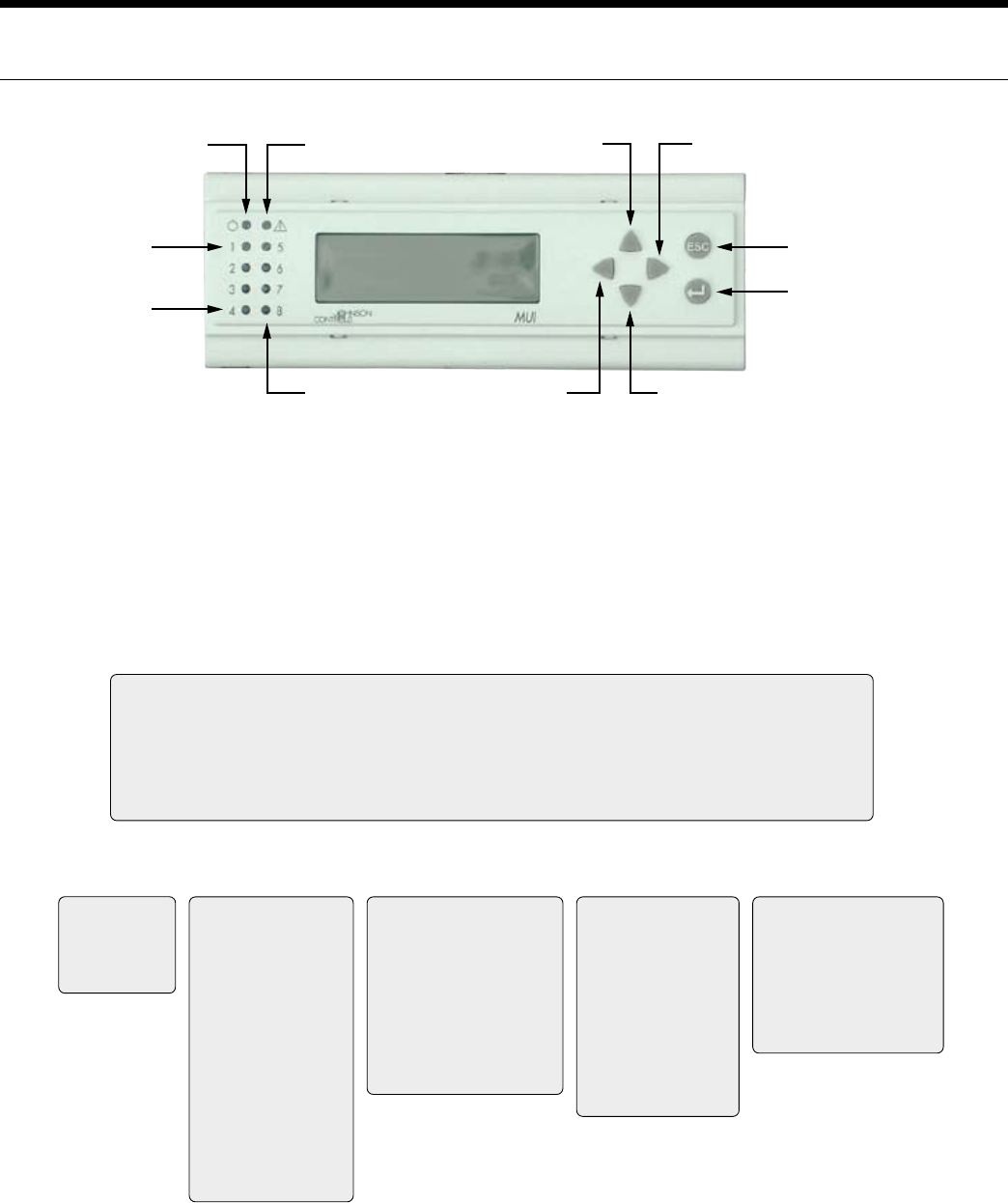
33
ENVISION CONSOLE INSTALLATION MANUAL
Envision Console Controls
FX10 User Interface (MUI) Physical Layout
Power LED
LED 1
LED 4
Escape (ESC)
Button
Return Button
Alarm LED
LED 8
Up Arrow Right Arrow
Left Arrow Down Arrow
Alarm LED - Indicates a Lock-Out or a bad Freeze Sensor
Power LED - Shows FX processor is operational
LED 1 - Flashing shows Compressor 1 running
LED 2 - Flashing shows Full Capacity Compressor running
LED 3 - On shows Fan running
LED 4 - On shows Reversing Valve in cool
LED 8 - Flashing shows unit in ‘Test’ Mode
MUI Menu Navigation for Single Compressor - Envision Water-to-Air
Welcome
Info Status Temps Outputs Settings Maint Alarms Alm-History
WFI
Envision Series
PROFXENV-XX
3/8/07
Info
Run Mode Auto
Eff Occup’y Occ
Y1 Input OFF
Y2 Input OFF
G Input OFF
O Input OFF
Occ Input Occ
Temp Occ Inp OFF
Condensate NML
Emg Input Run
Lo Press ON
Hi Press ON
Rndm Tmr 0
BI-4 Input OFF
Status
Zone Temp 77.2 ºF
Dis Air Temp 51.0 ºF
Eff Clg Setpt 70.0°F
Eff Htg Setpt 66.0°F
Water Coil 77.8°F
Low WC Limit 30.0°F
Humidity 56.7 %RH
WarmCool AI 14.6
WarmCoolAdj 0.2
Temps
nvoFanStatus ON
CmpCmd Status OFF
Cmp Capacity OFF
Rev Valve Heat
X1 Output OFF
X2 Output OFF
PWMOut 98%
BO5 OFF
BO9 OFF
AO2 Output 0%
Outputs Settings
Unit of Measure F
Occ Clg Setpt 73.9 ºF
Occ Htg Setpt 69.9 ºF
Unocc Clg 84.0 ºF
Unocc Htg 60.0 ºF
DeHumSetpt 0%
SensorSelect TAXXJ02
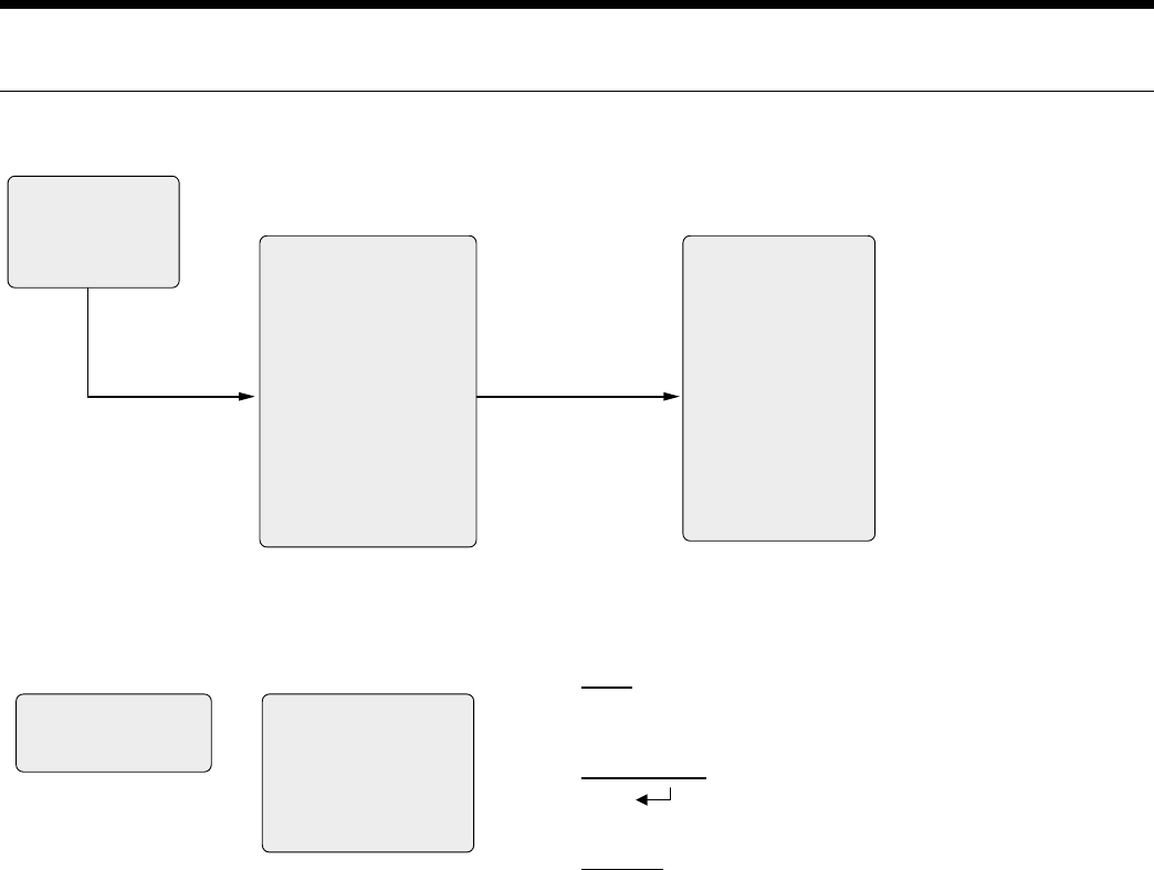
34
ENVISION CONSOLE INSTALLATION MANUAL
Envision Console Controls
LOG_IN REQUIRED
User : <= maint =>
Code : 5667
Maint
Maintenance
MinClgSetpt 60.0 ºF
MaxHtgSetpt 89.9 ºF
W Coil LoLim1 30.0 ºF
W Coil LoLim2 15.0 ºF
TmpOccTime 120 min
Rev Vlv Default Heating
BO5 Mode Network
CompStrtDly 90 sec
SpaceT Offset -1 ºF
DehumEnaDis Dis
Acc1 Action On Comp
Acc2 Action On Fan
SW1 OFF
SW2 OFF
SW3 ON
SW4 OFF
SW5 OFF
SW6 OFF
SW7 ON
SW8 OFF
SW9 OFF
SW10 ON
SW11 OFF
SW12 OFF
ECM
ALARM SUMMARY
^/High Pressure
Alarms
Press right arrow key
one time from
Maintenance Menu
No more than three
speeds should be “ON”
at one time
Alarm #Events
Condensate 0
Hi Pressure 0
Low Pressure 0
Low Temp 0
Bad Sensor 0
Alm-History NOTE: This FX10 application implements an alarm history which is reset
only by cycling power . This history shows on the Alm-History page. Any
alarm showing 4+ events has occurred more than 4 times.
Alarm lock-outs are reset by cycling power, by pressing the “ESC” and
Return keys simultaneously for a minimum of 15 seconds, or by
commanding the nviAlarmReset over the BAS network.
Test mode is enabled by holding the ‘Esc’ and Down Arrow simultaneously
for a minimum of 15 seconds and releasing. Test mode times out after 30
minutes, and may also be ended by pressing ‘ESC’ and Up Arrow
simultaneously and releasing . Test Mode bypasses the On Delay (90 sec)
and Random Start timers for quicker troubleshooting. It also allows cycling
the reversing valve without compressor shutdown.
MUI Menu Navigation for Single Compressor - Envision Water-to-Air
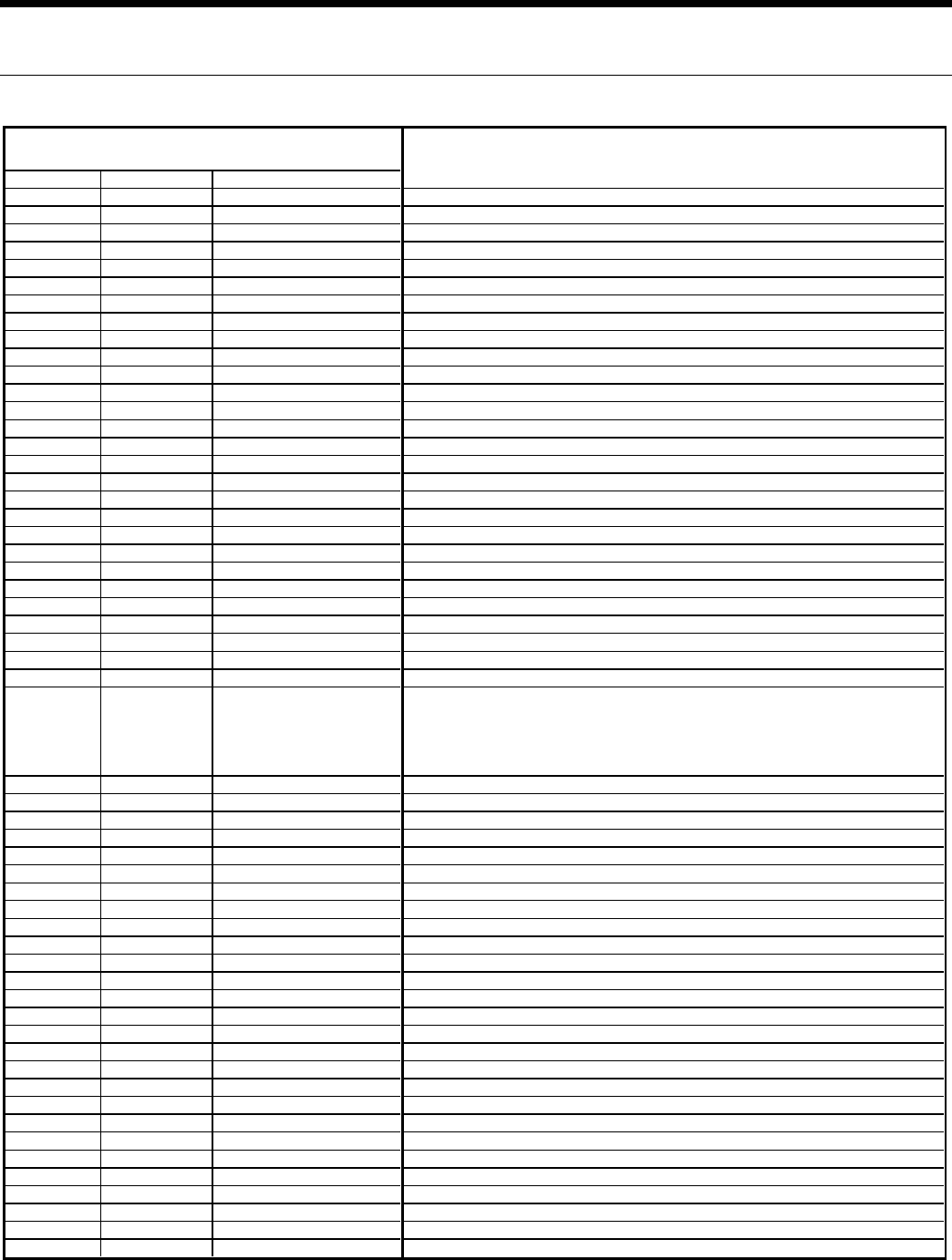
35
ENVISION CONSOLE INSTALLATION MANUAL
Point Type Point Address Long Name
ADF 1 nciSetpoints.Occupied_Co Occupied Cooling Setpoint Input (Read/Write)
ADF 2 nciSetpoints.Standby_Coo Standby Cooling Setpoint Input (Read/Write)
ADF 3 nciSetpoints.Unoccupied_ Unoccupied Cooling Setpoint Input (Read/Write)
ADF 4 nciSetpoints.Occupied_He Occupied Heating Setpoint Input (Read/Write)
ADF 5 nciSetpoints.Standby_Hea Standby Heating Setpoint Input (Read/Write)
ADF 6 nciSetpoints.Unoccupi5#6 Unoccupied Heating Setpoint Input (Read/Write)
ADF 7 nciMinClgSetpt Minimum Cooling Setpoint Input (Read/Write)
ADF 8 nciMaxHtgSetpt Maximum Heating Setpoint Input (Read/Write)
ADF 9 nvoSpaceTemp Space or Zone Temperature Value (Read Only)
ADF 10 nvoDischAirTemp Discharge Air Temp Field Supplied Only (Read Only)
ADF 11 nvoEffClgSetpt Effective Cooling Setpoint Value (Read Only)
ADF 12 nviSpaceTemp Space or Zone Temperature Value Override(Write)
ADF 64 nvoEffHtgSetpt Effective Heating Setpoint Value (Read Only)
ADF 54 nciAux5LevP Dehumidification Setpoint (Read/Write)
ADF 15 nciAux1Temp Heating Freeze Protection Temperature Setpoint Value (Read/Write)
ADF 16 nciAux2Temp Heating Freeze Protection Temperature Setpoint Value (Read/Write)
ADF 17 nvoUnitStatus.Heat_Outpu 1st Stage Compressor Heating Output (Read Only)
ADF 19 nvoUnitStatus.Cool_Outpu 1st Stage Compressor Cooling Output (Read Only)
ADF 21 nvoUnitStatus.Fan_Output Fan Output (Read Only)
BD 9 nvoUnitStatus.Mode Unit Mode of Operation (Read Only)
BD 10 nvoUnitStatus.In_Alarm Unit Alarm mode (Read Only)
ADF 22 nciPropBand Heating/Cooling Prop Band Input (Read/Write)
ADF 23 nciRemoteSetptSpan Warm/Cool Adjust Span (Read/Write)
ADF 24 nciRemoteSetptBias Warm/Cool Adjust Offset Value (Read/Write)
ADF 27 nciTempOffset Space or Zone Temperature Sensor Calibration Input (Read/Write)
ADF 32 nviSetpoint General Setpoint Input (Read/Write)
ADF 39 nvoHtgFrzPro1Tmp Heating Freeze Sensing Temperature Value (Read Only)
ADF 40 nvoHtgFrzSetpt Heating Freeze Sensing Temperature Setpoint Value (Read Only)
ADF 41 nvoAlarms
Alarms Enumerated [0=no alarms, 1=condensate alarm, 2=Compressor Hi Discharge
Pressure alarm, 3=Compressor low Suction Pressure alarm, 4=Freeze sensing
alarm, 8=Faulty Freeze Sensor alarm,
9=Loss of Charge]
(Read Only)
ADF 62 nvoPWMOut ECM PWM Control signal value (Read Only)
ADF 65 nvoECMOvrd ECM PWM Control signal Override (Read/Write)
ADF 63 nvoHumidity Space Humidity value (Read Only)
ADF 66 nviAO2 Spare PWM Output AO2 Command (Write)
ADF 67 nvoAO2 Spare PWM Output AO2 Value (Read Only)
ADI 2 nciBypassTime Temporary Occupancy Time Period Input (Read/Write)
BD 1 nvoEffectOccup Effective Occupancy State (Read Only)
BD 2 nviOccManCmd Occupancy Override Command Input (Read/Write)
BD 4 nviEmergOverride Emergency Override Input (Read/Write)
BD 5 nvoFanStatus Fan Output Status (Read Only)
BD 6 nvoAccStatus Accessory 2 Output Status (Read Only)
BD 7 nvoLP_WVStatus Accessory 1 Output Status (Read Only)
BD 8 nvoAlarmStatus Alarm Output Status (Read Only)
BD 12 nviAlarmReset Alarm Reset Input (Read/Write)
BD 13 nviFanSpeedCmd.State Network equivelant of a thermostatic 'G' call. (Write)
BD 14 nviComprEnable.State Network equivelant of a thermostatic 'Y1' call. (Write)
BD 46 nviY2HiSpeed.State Network equivelant of a thermostatic 'Y2' call. (Write)
BD 18 nvoRV1Status Reversing Valve Output Status (Read Only)
BD 22 nviOccSchedule.Current_s Occupancy Supervisory Scheduler Command Input (Read/Write)
BD 25 nvoCompFanProv Compressor/Fan Proving Switch Status (Read Only)
BD 24 nvoDirtyFilter Dirty Filter Switch Status (Read Only)
BD 26 nvoComp2Status Compressor Hi Capacity Command Status (Read Only)
BD 42 nviBO5 Command for output BO5 used for Emg Heat-Interlocked with Fan DP9Read/Write)
BD 41 nviBO9 Command for output BO9(Read/Write)
BD 47 nvoBO5 Value output for BO5 used for Emg Heat (Read Only)
BD 48 nvoBO9 Value output for BO9 (Read Only)
BD 44 nviDehumEna.State Dehumidification command-like a Humidistat (Read/Write)
Point Description
N2 Open
N2
Envision Console Controls
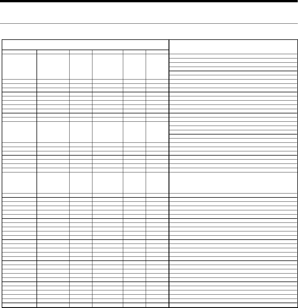
36
ENVISION CONSOLE INSTALLATION MANUAL
LonWorks Name SNVT Type SNVT Index SCPT Reference SCPT Index UCPT Index
Occupied Cooling Setpoint Input (Read/Write)
Standby Cooling Setpoint Input (Read/Write)
Unoccupied Cooling Setpoint Input (Read/Write)
Occupied Heating Setpoint Input (Read/Write)
Standby Heating Setpoint Input (Read/Write)
Unoccupied Heating Setpoint Input (Read/Write)
nciMinClgSetpt SNVT_temp_p 105 4 Minimum Cooling Setpoint Input (Read/Write)
nciMaxHtgSetpt SNVT_temp_p 105 3 Maximum Heating Setpoint Input (Read/Write)
nvoSpaceTemp SNVT_temp_p 105 Space or Zone Temperature Value (Read Only)
nvoDischAirTemp SNVT_temp_p 105 Discharge Air Temp Field Supplied Only (Read Only)
nvoEffClgSetpt SNVT_temp_p 105 Effective Cooling Setpoint Value (Read Only)
nviSpaceTemp SNVT_temp_p 105 Space or Zone Temperature Value Override(Write)
nvoEffHtgSetpt SNVT_temp_p 105 Effective Heating Setpoint Value (Read Only)
nciAux5LevP SNVT_lev_percent 81 Dehumidification Setpoint (Read/Write)
nciAux1Temp SNVT_temp_p 105 147 Heating Freeze Protection Temperature Setpoint Value (Read/Write)
nciAux2Temp SNVT_temp_p 105 148 Heating Freeze Protection Temperature Setpoint Value (Read/Write)
1st Stage Compressor Heating Output (Read Only)
1st Stage Compressor Cooling Output (Read Only)
Fan Output (Read Only)
Unit Mode of Operation (Read Only)
Unit Alarm mode (Read Only)
nciPropBand SNVT_temp_diff_p 147 177 Heating/Cooling Prop Band Input (Read/Write)
nciRemoteSetptMin SNVT_temp_diff_p 147 98 Warm/Cool Adjust Span (Read/Write)
nciRemoteSetptMax SNVT_temp_diff_p 147 97 Warm/Cool Adjust Offset Value (Read/Write)
nciTempOffset SNVT_temp_diff_p 147 11 Space or Zone Temperature Sensor Calibration Input (Read/Write)
nviSetpoint SNVT_temp_p 105 General Setpoint Input (Read/Write)
nvoHtgFrzPro1Tmp SNVT_temp_p 105 Heating Freeze Sensing Temperature Value (Read Only)
nvoHtgFrzSetpt SNVT_temp_p 105 Heating Freeze Sensing Temperature Setpoint Value (Read Only)
nvoAlarms SNVT_lev_cont 21
Alarms Enumerated [0=no alarms, 1=condensate alarm, 2=Compressor Hi Discharge
Pressure alarm, 3=Compressor low Suction Pressure alarm, 4=Freeze sensing
alarm, 8=Faulty Freeze Sensor alarm,
9=Loss of Charge]
(Read Only)
nvoPWMOut SNVT_volt 44 ECM PWM Control signal value (Read Only)
nvoECMOvrd SNVT_volt 44 ECM PWM Control signal Override (Read/Write)
nvoHumidity SNVT_volt 44 Space Humidity value (Read Only)
nviAO2 SNVT_lev_percent 81 Spare PWM Output AO2 Command (Write)
nvoAO2 SNVT_lev_percent 81 Spare PWM Output AO2 Value (Read Only)
nciBypassTime SNVT_time_min 123 SCPTbypassTime 34 Temporary Occupancy Time Period Input (Read/Write)
nvoEffectOccup SNVT_occupancy 109 Effective Occupancy State (Read Only)
nviOccManCmd SNVT_occupancy 109 Occupancy Override Command Input (Read/Write)
nviEmergOverride SNVT_hvac_emerg 103 Emergency Override Input (Read/Write)
nvoFanStatus SNVT_lev_disc 22 Fan Output Status (Read Only)
nvoAccStatus SNVT_lev_disc 22 Accessory 2 Output Status (Read Only)
nvoLP_WVStatus SNVT_lev_disc 22 Accessory 1 Output Status (Read Only)
nvoAlarmStatus SNVT_lev_disc 22 Alarm Output Status (Read Only)
nviAlarmReset SNVT_lev_disc 22 Alarm Reset Input (Read/Write)
nviFanSpeedCmd.StateSNVT_switch 95 Network equivelant of a thermostatic 'G' call. (Write)
nviComprEnable.State SNVT_switch 95 Network equivelant of a thermostatic 'Y1' call. (Write)
nviComprEnable.State SNVT_switch 95 Network equivelant of a thermostatic 'Y2' call. (Write)
nvoRV1Status SNVT_lev_disc 22 Reversing Valve Output Status (Read Only)
nviOccSchedule SNVT_tod_event 128 Occupancy Supervisory Scheduler Command Input (Read/Write)
nvoCompFanProv SNVT_lev_disc 22 Compressor/Fan Proving Switch Status (Read Only)
nvoDirtyFilter SNVT_lev_disc 22 Dirty Filter Switch Status (Read Only)
nvoComp2Status SNVT_lev_disc 22 Compressor Hi Capacity Command Status (Read Only)
nviBO5 SNVT_lev_disc 22 Command for output BO5 used for Emg Heat-Interlocked with Fan DP9Read/Write)
nviBO9 SNVT_lev_disc 22 Command for output BO9(Read/Write)
nvoBO5 SNVT_lev_disc 22 Value output for BO5 used for Emg Heat (Read Only)
nvoBO9 SNVT_lev_disc 22 Value output for BO9 (Read Only)
nviDehumEna.State SNVT_lev_disc 22 Dehumidification command-like a Humidistat (Read/Write)
Point Description
60
LonWorks
SCPTsetPntsnciSetpoints SNVT_temp_setpt 106
nvoUnitStatus SNVT_hvac_type 112
LonWorks
Envision Console Controls
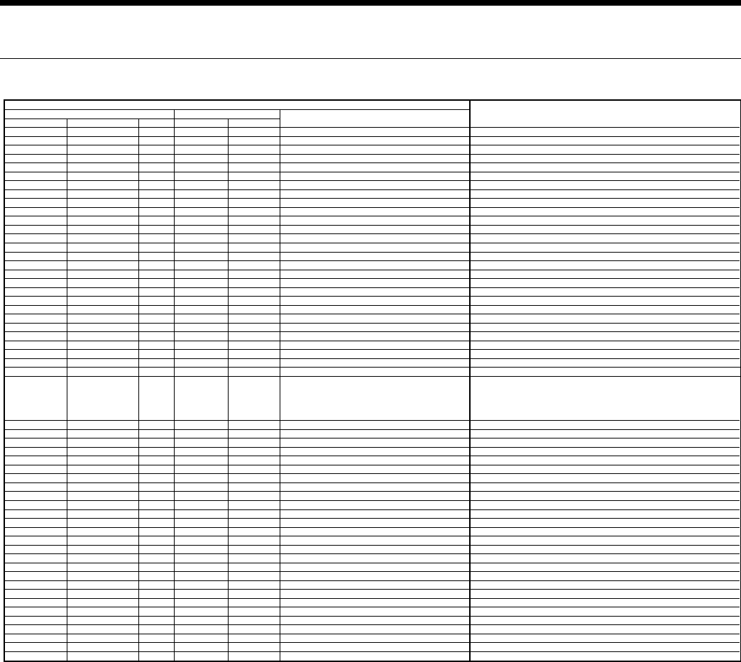
37
ENVISION CONSOLE INSTALLATION MANUAL
Object Type Type Enumeration Instance Name Enumeration
Analog Value 2 1 Present_Value 85 WFI##########.Occupied Cool.Present_Value Occupied Cooling Setpoint Input (Read/Write)
Standby Cooling Setpoint Input (Read/Write)
Analog Value 2 2 Present_Value 85 WFI##########.Unoccupied Cool.Present_Value Unoccupied Cooling Setpoint Input (Read/Write)
Analog Value 2 3 Present_Value 85 WFI##########.Occupied Heat.Present_Value Occupied Heating Setpoint Input (Read/Write)
Standby Heating Setpoint Input (Read/Write)
Analog Value 2 4 Present_Value 85 WFI##########.Unoccupied Heat.Present_Value Unoccupied Heating Setpoint Input (Read/Write)
Minimum Cooling Setpoint Input (Read/Write)
Maximum Heating Setpoint Input (Read/Write)
Analog Input 0 1 Present_Value 85 WFI##########.Space Temp.Present_Value Space or Zone Temperature Value (Read Only)
Analog Input 0 2 Present_Value 85 WFI##########.Discharge Air Temp.Present_Value Discharge Air Temp Field Supplied Only (Read Only)
Analog Input 0 3 Present_Value 85 WFI##########.Effective Clg Setpt.Present_Value Effective Cooling Setpoint Value (Read Only)
Analog Output 1 4 Present_Value 85 WFI##########.Space temp Ovrd.Present_Value Space or Zone Temperature Value Override(Write)
Analog Input 0 4 Present_Value 85 WFI##########.Effective Htg Setpt.Present_Value Effective Heating Setpoint Value (Read Only)
Analog Value 2 9 Present_Value 85 WFI##########.Dehumidify Setpt.Present_Value Dehumidification Setpoint (Read/Write)
Analog Value 2 10 Present_Value 85 WFI##########.Low Temp Limit Adj.Present_Value Heating Freeze Protection Temperature Setpoint Value (Read/Write)
Heating Freeze Protection Temperature Setpoint Value (Read/Write)
1st Stage Compressor Heating Output (Read Only)
1st Stage Compressor Cooling Output (Read Only)
Fan Output (Read Only)
Multistate Input 13 2 Present_Value 85 WFI##########.Mode.Present_Value Unit Mode of Operation (Read Only)
Unit Alarm mode (Read Only)
Heating/Cooling Prop Band Input (Read/Write)
Analog Value 2 6 Present_Value 85 WFI##########.Remote Setpt Span.Present_Value Warm/Cool Adjust Span (Read/Write)
Analog Value 2 7 Present_Value 85 WFI##########.Remote Setpt Bias.Present_Value Warm/Cool Adjust Offset Value (Read/Write)
Analog Value 2 8 Present_Value 85 WFI##########.Space Temp Offset.Present_Value Space or Zone Temperature Sensor Calibration Input (Read/Write)
Analog Output 1 1 Present_Value 85 WFI##########.Space Setpoint.Present_Value General Setpoint Input (Read/Write)
Analog Input 0 6 Present_Value 85 WFI##########.Water Coil Temp.Present_Value Heating Freeze Sensing Temperature Value (Read Only)
Analog Input 0 7 Present_Value 85 WFI##########.Low Temp Limit.Present_Value Heating Freeze Sensing Temperature Setpoint Value (Read Only)
Analog Input 0 9 Present_Value 85 WFI##########.Alarms Enumerated.Present_Value
Alarms Enumerated [0=no alarms, 1=condensate alarm, 2=Compressor Hi Discharge
Pressure alarm, 3=Compressor low Suction Pressure alarm, 4=Freeze sensing
alarm, 8=Faulty Freeze Sensor alarm,
9=Loss of Charge]
(Read Only)
Analog Input 0 8 Present_Value 85 WFI##########.ECM Cmd Output.Present_Value ECM PWM Control signal value (Read Only)
Analog Output 1 2 Present_Value 85 WFI##########.ECM Fan Ovrd.Present_Value ECM PWM Control signal Override (Read/Write)
Analog Input 0 5 Present_Value 85 WFI##########.Space Humidity.Present_Value Space Humidity value (Read Only)
Analog Output 1 3 Present_Value 85 WFI##########.AO2 Override.Present_Value Spare PWM Output AO2 Command (Write)
Analog Input 0 10 Present_Value 85 WFI##########.AO2 Value.Present_Value Spare PWM Output AO2 Value (Read Only)
Analog Value 2 5 Present_Value 85 WFI##########.Temporary Occ Time.Present_Value Temporary Occupancy Time Period Input (Read/Write)
Multistate Input 13 1 Present_Value 85 WFI##########.Effective Occupancy.Present_Value Effective Occupancy State (Read Only)
Multistate Output 14 1 Present_Value 85 WFI##########.Occupancy Command.Present_Value Occupancy Override Command Input (Read/Write)
Multistate Output 14 6 Present_Value 85 WFI##########.Emergency Override.Present_Value Emergency Override Input (Read/Write)
Binary Input 3 1 Present_Value 85 WFI##########.Fan Cmd Status.Present_Value Fan Output Status (Read Only)
Binary Input 3 6 Present_Value 85 WFI##########.Accessory 2 Output.Present_Value Accessory 2 Output Status (Read Only)
Binary Input 3 5 Present_Value 85 WFI##########.Accessory 1 Output.Present_Value Accessory 1 Output Status (Read Only)
Binary Input 3 8 Present_Value 85 WFI##########.Alarm Status.Present_Value Alarm Output Status (Read Only)
Multistate Output 14 7 Present_Value 85 WFI##########.Alarm Reset.Present_Value Alarm Reset Input (Read/Write)
Multistate Output 14 2 Present_Value 85 WFI##########.Fan Command (G).Present_Value Network equivelant of a thermostatic 'G' call. (Write)
Multistate Output 14 3 Present_Value 85 WFI##########.Compressor Cmd (Y1).Present_Value Network equivelant of a thermostatic 'Y1' call. (Write)
Multistate Output 14 3 Present_Value 85 WFI##########.Compressor Cmd (Y2).Present_Value Network equivelant of a thermostatic 'Y2' call. (Write)
Binary Input 3 4 Present_Value 85 WFI##########.Reversing Valve.Present_Value Reversing Valve Output Status (Read Only)
Occupancy Supervisory Scheduler Command Input (Read/Write)
Compressor/Fan Proving Switch Status (Read Only)
Binary Input 3 7 Present_Value 85 WFI##########.Dirty Filter (BI-12).Present_Value Dirty Filter Switch Status (Read Only)
Binary Input 3 3 Present_Value 85 WFI##########.Comp Hi Capacity Cmd.Present_Value Compressor Hi Capacity Command Status (Read Only)
Multistate Output 14 8 Present_Value 85 WFI##########.Emergency Heat BO5.Present_Value Command for output BO5 used for Emg Heat-Interlocked with Fan DP9Read/Write)
Multistate Output 14 9 Present_Value 85 WFI##########.BO9.Present_Value Command for output BO9(Read/Write)
Binary Input 3 9 Present_Value 85 WFI##########.BO5 Output.Present_Value Value output for BO5 used for Emg Heat (Read Only)
Binary Input 3 10 Present_Value 85 WFI##########.BO9 Output.Present_Value Value output for BO9 (Read Only)
Multistate Output 14 10 Present_Value 85 WFI##########.Dehum Cmd.Present_Value Dehumidification command-like a Humidistat (Read/Write)
Point Description
Object Identifier Property
BACnet
Full Reference
BACNet
Envision Console Controls

38
ENVISION CONSOLE INSTALLATION MANUAL
BACnet Variables
Envision Console Controls
The variables will be listed with the point type and instance
preceding the variable name.
Analog Input (Type 0)
0:1 Space Temp
[Read only, shows the space temperature]
0:2 Discharge Air Temp
[Read only, field mounted sensor unless supplied
as a factory special]
0:3 Effective Clg Setpt
[Read only, shows the active cooling setpoint]
0:4 Effective Htg Setpt
[Read only, shows the active heating setpoint]
0:5 Space Humidity
[Read]
0:6 Water Coil Temp
[Read, shows the refrigerant temperature at its
coldest, for predictive freeze condition detection]
0:7 Low Temp Limit
[Read, shows the water coil low temperature (freeze
sensing) limit that will result in unit shutdown.]
0:8 ECM Cmd Output
[Read, shows the commanded speed (0-100%) of
the ECM Blower]
0:9 Alarms Enumerated
[Read only, 0=no alarms, 1=condensate alarm,
2=Compressor Hi Discharge Pressure alarm,
3=Compressor low Suction Pressure alarm,
4=Freeze sensing alarm, 8=Faulty Freeze Sensor
alarm, 9=Loss of Charge]
0:10 AO2 Value
[Read, shows the output value (0-100%) of AO2]
Analog Output (Type 1)
1:1 Space Setpoint
[Write, Raise and lower the heating and cooling
setpoints from a single command point(volatile,
reverts to ‘uncommanded’ after power outage).]
1:2 ECM Fan Ovrd
[Write, allows network direct control of the ECM
blower speed (volatile, reverts to ‘uncommanded’
after power outage)]
1:3 AO2 Override
[Write, allows network direct control of the Analog
Output 2, volatile, reverts to ‘uncommanded’ after
power outage)]
1:4 Space temp Ovrd
[Write, allows the network to send space
temperature values to the heat pump controller,
volatile, these will supersede any temperature
sensor connected to the space temperature Analog
Input.]
Analog Value (Type 2)
2:1 Occupied Cool
[Write, Cooling setpoint in Occupied mode]
2:2 Unoccupied Cool
[Write, Cooling setpoint in Unoccupied mode]
2:3 Occupied Heat
[Write, Heating setpoint in Occupied mode]
2:4 Unoccupied Heat
[Write, Heating setpoint in Unoccupied mode]
2:5 Temporary Occ Time
[Write, set the duration of the temporary occupancy
timer which is initiated by pressing the button on the
zone sensor]
2:6 Remote Setpt Span
[Write, sets the offset range that the setpoint knob
on the zone sensor may apply to the effective Htg/
Clg setpoints]
2:7 Remote Setpt Bias
[Write, biases the entire readjust range of the
remote setpoint adjust to allow zeroing from the
network.]
2:8 Space Temp Offset
[Write, Adds an offset to the Space Temp value for
calibration]
2:9 Dehumidify Setpt
[Write, sets the humidity value that will cause the
heat pump to enter passive dehumidification]
2:10 Low Temp Limit Adj
[Write, sets the water coil low temperature (freeze
sensing) limit for shutdown]
Binary Input (Type 3)
3:1 Fan Cmd Status
[Read, show the commanded condition of the Fan
Output,Inactive=Off, Active=On]
3:2 Comp Cmd Status
[Read, show the commanded condition of the
Compressor Output, Inactive=Off, Active=On]
3:3 Comp Hi Capacity Cmd
[Read, show the commanded condition of the ‘Hi
Capacity’ Compressor control, Inactive=Off,
Active=On.]
3:4 Reversing Valve
[Read, show the commanded condition of the
Reversing Valve Output, Inactive =Heating,
Active =Cooling]
3:5 Accessory 1 Output
[Read, Shows the commanded value of the X1
(Accessory
3:8 Alarm Status
[Read, shows the in alarm/out of alarm status,
Inactive=Off, Active=On]

39
ENVISION CONSOLE INSTALLATION MANUAL
BACnet Variables
Envision Console Controls
3:9 BO5 Output
[Read, shows the BO5 (electric heat) output value,
Inactive=Off, Active=On]
3:10 BO9 Output
[Read, shows the BO9 output value, Inactive=Off,
Active=On]
Multistate Input (Type 13)
13:1 Effective Occupancy
[Read, show the prevailing occupancy status of
the heatpump1=Occupied, 2=Unoccupied,
3=Bypass, 255=Invalid]
13:2 Mode Status
[Read, Shows unit status as Auto or Shutdown,
1=Auto, 7=Shutdown]
Multistate Output (Type 14)
14:1 Occupancy Command
[Write, Control the occupancy mode of the
heatpump. 1=Occupied, 2=Unoccupied, 3=Bypass,
255=Invalid]
14:2 Fan Command (G)
[Write, allows a network command equivalent of
a thermostatic ‘G’ call]
14:3 Compressor Cmd (Y1)
[Write, allows a network command equivalent of a
thermostatic ‘Y1’ call]
14:4 Compressor Cmd (Y2)
[Write, allows a network command equivalent of a
thermostatic ‘Y2’ call]
14:5 Reversing Vlv Cmd (O)
[Write, allows a network command equivalent of a
thermostatic ‘O’ call]
14:6 Emergency Overide
[Write, provide rapid shutdown of the heatpump
for fire,etc. 1=Normal, 5=Shutdown]
14:7 Alarm Reset
[Write, Reset lock-out ‘manual reset’ alarms. Alarm
conditions must be cleared before a reset can
succeed. This variable should be commanded
‘On’ for 20 seconds, then returned to the ‘Off’
condition. 1=Off, 2=On]
14:8 Emergency Heat BO5
[Write, allows a network command for emergency
heat, also allows the network to stop automatic
emergency heat.]
14:9 BO9
[Write, allow network control of spare output BO9.
1 = Off, 2=On.]
14:10 Dehum Cmd

40
ENVISION CONSOLE INSTALLATION MANUAL
Unit Startup Notes
Emergency Electric Resistance Heat
A factory-installed emergency electric heater package is
available. Rated for 2,000 watts on models NC09 through
NC12 and 3,000 watts on models NC15 through NC18.
The heater package consists of ni-cad elements, ceramic
insulators, and thermal limit switches. A concealed, chassis
mounted rocker switch controls the heater mode operation
and allows the field installation of an aquastat for boilerless
unit operation.
Electrical Disconnect
Field installed on the optional chassis back plate, the con-
sole disconnect provides a permanent electrical connection
to the main electrical supply branch. Wiring between the
disconnect and the unit chassis is field supplied and allows
the electrical power source to the chassis to be interrupted
for unit servicing.
Non-Fused
Constructed of heavy gauge galvanized steel, the
rocker style disconnect switch provides reliable electri-
cal control. Wiring pigtails, using 12-gauge wires, are
factory installed to simplify field wiring.
Fused
Similar in construction to the non-fused electrical
disconnect. The fused disconnect is available in five
models with equipment rated fuses to provide addi-
tional circuit protection. The fuses are panel mounted
to allow easy inspection and removal without removing
the cover on the disconnect.
CFD-10 - 10 amp rated fuse
CFD-12 - 12 amp rated fuse
CFD-15 - 15 amp rated fuse
CFD-20 - 20 amp rated fuse
CFD-25 - 25 amp rated fuse
Motorized Outside Air Damper
A field installed motorized outside air damper is available
to allow the introduction of fresh air into the conditioned
space through an outside vent. The damper motor is pow-
ered by 24 volts with a spring-close design in the event of
a power failure. The damper blade and housing are con-
structed of aluminum for corrosion resistance and the blade
includes a neoprene gasket to prevent air infiltration during
off cycles. The damper assembly is installed on the optional
chassis back plate and a two-wire low voltage connection
simplifies wiring. A concealed, chassis mounted rocker
switch allows the damper to be disabled
Hydronic Loop Controller for
Boiler/Tower Installations
The hydronic loop controller is a microprocessor based
control panel for control of water loop heat rejector (tower),
heat supplier (boiler), and/or water well pumps and circula-
tion pumps. Includes audible and visual alarms, temperature
indication, and add-on options of low switches, remote
alarm sensor wells and pump alternator.

41
ENVISION CONSOLE INSTALLATION MANUAL
Unit Startup Checklist / Unit Startup Steps
Before Powering Unit, Check The Following:
High voltage is correct and matches nameplate.•
Fuses, breakers and wire size correct.•
Low voltage wiring complete.•
Piping completed and water system cleaned and flushed.•
Air is purged from closed loop system.•
Isolation valves are open, water control valves or loop pumps wired.•
Condensate line open and correctly pitched.•
Transformer switched to 208V if applicable.•
Dip switches are set correctly, if applicable.•
Blower rotates freely•
Air filter is clean and in position.•
Service/access panels are in place.•
Return air temperature is between 50-80ºF heating and 60-95ºF cooling.•
Check air coil cleanliness to insure optimum performance. Clean as needed according to maintenance guidelines. To •
obtain maximum performance the air coil should be cleaned before startup. A 10-percent solution of dishwasher
detergent and water is recommended for both sides of coil, a thorough water rinse should follow.
Startup Steps
Note: Complete the Equipment Start-Up/Commissioning Check Sheet during this procedure. Refer to thermostat
operating instructions and complete the startup procedure.
1. Initiate a control signal to energize the blower motor. Check blower operation.
2. Initiate a control signal to place the unit in the cooling mode. Cooling setpoint must be set below room temperature.
3. Be sure that the compressor and water control valve or loop pump(s) are activated.
4. Verify that the water flow rate is correct by measuring the pressure drop through the heat exchanger using the P/T
plugs and comparing to unit capacity data in specification catalog.
5. Check the temperature of both the supply and discharge water (Refer to Unit Operating Parameters tables).
6. Check for an air temperature drop of 15°F to 25°F across the air coil, depending on the fan speed and entering water
temperature.
7. Adjust the cooling setpoint above the room temperature and verify that the compressor and water valve or loop
pumps deactivate.
8. Initiate a control signal to place the unit in the heating mode. Heating set point must be set above room temperature.
9. Check the temperature of both the supply and discharge water (Refer to Unit Operating Parameters tables).
10. Check for an air temperature rise of 20°F to 35°F across the air coil, depending on the fan speed and entering water
temperature.
11. Adjust the heating setpoint below room temperature and verify that the compressor and water valve or loop pump
deactivate.
12. During all testing, check for excessive vibration, noise or water leaks. Correct or repair as required.
13. Set system to desired normal operating mode and set temperature to maintain desired comfort level.
14. Instruct the owner/operator in the proper operation of the thermostat and system maintenance.
Note: Be certain to fill out and forward all warranty registration papers.
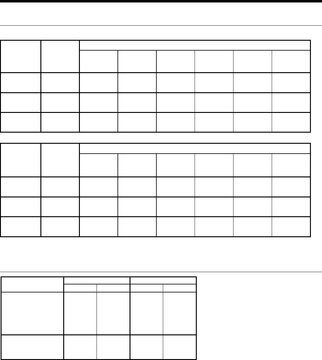
42
ENVISION CONSOLE INSTALLATION MANUAL
Entering
Water Temp
°F
Water Flow
GPM/Ton
Cooling
Suction
Pressure
PSIG
Discharge
Pressure
PSIG
09-18
Superheat
09-18
Subcooling
Water Temp
Rise °F
Air Temp
Drop °F DB
50 1.5 127 - 144 205 - 225 5 - 10 10 - 14 18 - 22 18 - 22
3.0 120 - 140 185 - 205 7 - 15 5 - 10 8 - 10 18 - 22
70 1.5 139 - 154 280 - 300 8 - 11 8 -12 18 - 22 18 - 22
3.0 137 - 152 250 - 270 9 - 12 7 - 11 8 - 10 18 - 22
90 1.5 143 - 158 360 - 380 8 - 11 9 - 13 18 - 22 16 - 20
3.0 141 - 156 330 - 350 9 - 12 8 - 12 8 - 10 16 - 20
Entering
Water Temp
°F
Water Flow
GPM/Ton
Heating
Suction
Pressure
PSIG
Discharge
Pressure
PSIG
09-18
Superheat
09-18
Subcooling
Water
Temp Drop
°F
Air Temp
Rise °F DB
30 1.5 73 - 79 279 - 304 7 - 13 2 - 6 7 -10 18 - 24
3.0 79 - 85 285 - 310 8 - 14 2 - 6 3 - 6 20 - 26
50 1.5 103 - 109 308 - 333 8 - 12 4 - 8 8 - 11 20 - 26
3.0 110 - 116 315 - 340 9 - 13 4 - 8 4 - 7 22 - 28
70 1.5 140 - 146 330 - 365 10 - 14 7 - 11 11 - 14 26 - 32
3.0 146 - 153 340 - 375 10 - 14 7 - 11 7 - 10 28 - 34
Note: Cooling performance based on entering air temperatures of 80º F DB, 67º F WB.
Heating performance based on entering air temperature of 70º F DB.
Operating Limits (°F) (°C) (°F) (°C)
Air Limits
Min. Ambient Air 45 7.2 45 7.2
Rated Ambient Air 80 26.7 70 21.1
Max. Ambient Air 100 37.8 85 29.4
Min. Entering Air 50 10.0 40 4.4
Rated Entering Air db/wb 80.6/66.2 27/19 68 20.0
Max. Entering Air db/wb 110/83 43/28.3 80 26.7
Water Limits
Min. Entering Water 30 -1.1 20 -6.7
Normal Entering Water 50-110 10-43.3 30-70 -1.1
Max. Entering Water 120 48.9 90 32.2
Notes:
Cooling Heating
Minimum/maximum limits are only for start-up conditions, and are meant for bringing the space up to occupancy
temperature. Units are not designed to operate at the minimum/maximum conditions on a regular basis. The
operating limits are dependant upon three primary factors: 1) water temperature, 2) return air temperature, and 3)
ambient temperature. When any of the factors are at the minimum or maximum levels, the other two factors must be
at the normal level for proper and reliable unit operation.
Unit Operating Limits
Unit Operating Parameters
Single Speed Models
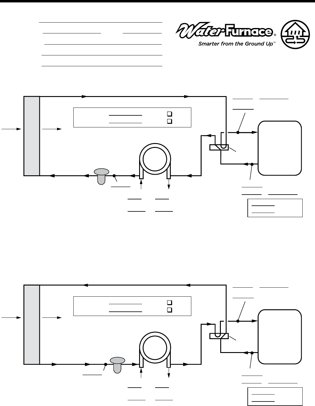
43
ENVISION CONSOLE INSTALLATION MANUAL
COOLING CYCLE ANALYSIS
EXPANSION
VALVE
°F AIR
COIL
°F°F
PSI PSI
BRINE IN BRINE OUT
COMPRESSOR
DISCHARGE
SUCTION
Subcooling
Superheat
REVERSING
VALVE
PSI
°F
SAT °F=
PSI = SAT F
F
°F
LIQUID LINE
°
°
°F
COAX
SOURCE
Heat of Extraction/Rejection = GPM x 500 (485 for water/antifreeze) x ∆T
Note: DO NOT hook up pressure gauges unless there appears to be a performance problem.
Line Voltage:
Loop: Open
Unit Amp Draw:
Closed
COAX
SOURCE
HEATING CYCLE ANALYSIS
EXPANSION
VALVE
°F AIR
COIL
°F°F
PSI PSI
BRINE IN BRINE OUT
COMPRESSOR
DISCHARGE
SUCTION
Subcooling
Superheat
REVERSING
VALVE
PSI
°F
SAT °F=
PSI = SAT F
F
F
LIQUID LINE
°
°
°
°F
Line Voltage:
Loop: Open
Unit Amp Draw:
Closed
DEALER:
PHONE #: DATE:
PROBLEM:
MODEL #:
SERIAL #:
Startup/Troubleshooting Form
WFS37 10/07

44
ENVISION CONSOLE INSTALLATION MANUAL
Pressure Drop
Model GPM Pressure Drop (psi)
30°F 50°F 70°F 90°F 110°F
09
1.2 1.0 0.9 0.8 0.7 0.6
1.8 2.3 2.2 2.0 1.9 1.8
2.5 3.8 3.7 3.5 3.3 3.1
12
1.5 0.9 0.8 0.7 0.6 0.5
2.3 1.7 1.5 1.4 1.3 1.1
3.5 3.0 2.7 2.5 2.4 2.2
15
2.0 1.7 1.6 1.5 1.4 1.3
3.0 3.3 3.2 3.0 2.9 2.8
4.5 5.7 5.5 5.3 5.1 4.9
18
3.0 1.7 1.6 1.5 1.4 1.3
4.0 4.1 4.0 3.9 3.7 3.6
5.5 7.9 7.6 7.4 7.2 6.9
3/4/08
45
ENVISION CONSOLE INSTALLATION MANUAL
Obtaining Parts
When ordering service or replacement parts, refer to the
model number and serial number of the unit as stamped on
the serial plate attached to the unit. If replacement parts
are required, mention the date of installation of the unit
and the date of failure, along with an explanation of the
malfunctions and a description of the replacement parts
required.
In-Warranty Material Return
Material may not be returned except by permission of au-
thorized warranty personnel. Contact your local distributor
for warranty return authorization and assistance.
CAUTION: Fin edges are sharp.
Preventive Maintenance
Replacement Procedures
Water Coil Maintenance
1. Keep all air out of the water. An open loop system should
be checked to ensure that the well head is not allowing
air to infiltrate the water line. Lines should always be
airtight.
2. Keep the system under pressure at all times. It is
recommended in open loop systems that the water
control valve be placed in the discharge line to prevent
loss of pressure during off cycles. Closed loop systems
must have positive static pressure.
Note: On open loop systems, if the installation is in an area
with a known high mineral content (125 PPM or greater) in
the water, it is best to establish with the owner a periodic
maintenance schedule so the coil can be checked regularly.
Should periodic coil cleaning be necessary, use standard
coil cleaning procedures which are compatible with either
the cupronickel or copper water lines. Generally, the more
water flowing through the unit the less chance for scaling.
Other Maintenance
Filters
Filters must be clean to obtain maximum performance.
They should be inspected monthly under normal operating
conditions and be replaced when necessary. Units should
never be operated without a filter.
Condensate Drain
In areas where airborne bacteria produce a slime in the
drain pan, it may be necessary to treat chemically to
minimize the problem. The condensate drain can pick up lint
and dirt, especially with dirty filters. Inspect twice a year to
avoid the possibility of overflow.
Blower Motors
Blower motors are equipped with sealed ball bearings and
require no periodic oiling.
Air Coil
The air coil must be cleaned to obtain maximum
performance. Check once a year under normal operating
conditions and, if dirty, brush or vacuum (with a brush
attachment) clean. Care must be taken not to damage the
aluminum fins while cleaning.

Product: Envision Series Console
Type: Geothermal/Water Source Heat Pumps
Size: 0.75-1.5 Ton
Document: Installation Manual
7;$' &
Manufactured by
WaterFurnace International, Inc.
9000 Conservation Way
Fort Wayne, IN 46809
www.waterfurnace.com
WaterFurnace International, Inc., 9000 Conservation Way, Fort Wayne, IN 46809-9794. WaterFurnace has a policy of continual product research and development and reserves
the right to change design and specications without notice. © 2008 WaterFurnace International Inc.
