EpiCom SXC-1180 SINGLE-BAND CDMA 2000 1x USB Dongle User Manual manual
EpiCom Co., Ltd. SINGLE-BAND CDMA 2000 1x USB Dongle manual
EpiCom >
manual
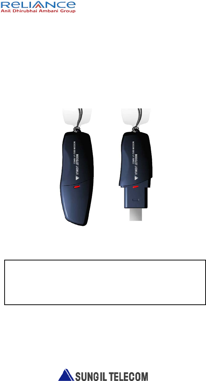
SXC-1180
CDMA 1x USB MODEM
Wherever you are.
Wherever you need
참고사항
노트북에 제품(SXC-1180)을 직접 연결하여 사용하는 경우, LCD모니터에서 발생하
는 전자파에 의해 수신 감도가 저하되는 경우가 있습니다.
이 경우 제품과 함께 동봉된 USB연장 케이블을 연결해 사용하시기를 권장합니다.
Introduction
Congratulations on your purchase of the advanced and compact SXC-
1180 USB Modem, designed to operate with the latest digital mobile
communication technology.
For Your Safety
Read these simple guidelines. Breaking the rules may be dangerous or illegal.
Further detailed information is given in this manual.
Warning
• USB Modem must be switched off at all times in an aircraft.
• Do not use your Modem near petrol stations, fuel depots, chemical plants or
blasting operations.
• For your safety, use ONLY specified note-book PC and desk-top PC
• Do not handle the modem with wet hands while it is being charged. It may
cause an electric shock or seriously Damage your modem.
• Keep the modem in a safe place out of small children’s reach. It includes small
parts which if detached may cause a choking hazard.
Caution
• Switch off the modem in any area where required by special regulations. For
example, do not use your modem in hospitals or it may affect sensitive medical
equipment.
• Emergency calls may not be available under all cellular networks. Therefore,
you should never depend solely on the modem for emergency calls.
• Only use ORIGINAL accessories to avoid damage to your modem.
• All radio transmitters carry risks of interference with electronics in close
proximity. Minor interference may affect TVs, radios, PCs, etc.
This user’s guide contains important information on the use and
operation of this phone. Please read all the information carefully for
optimal performance and ro prevent any damage to or misuse of the
USB Modem. Any changes or modifications not expressly approved in
this user’s guide could void your warranty for this equipment.
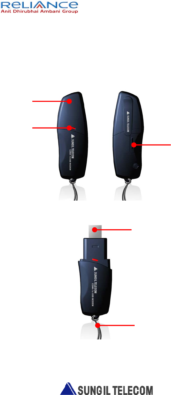
1. Part of the USB Modem
Indicator LED
R-UIM Socket
USB CONNECTOR
Neck Strap
USB Cover
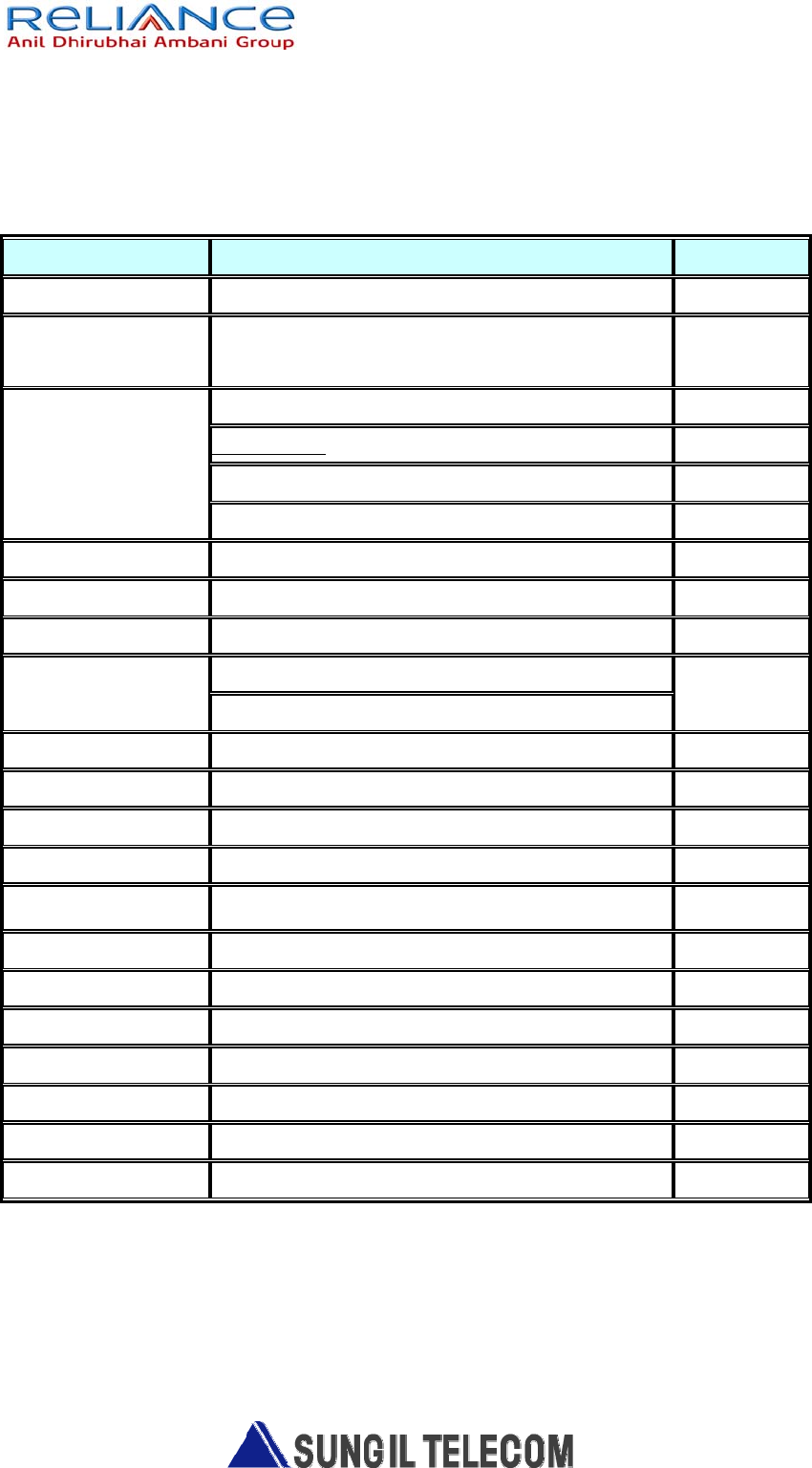
2. Product Specification
Function SXC-1180 Remarks
Main Operation Chip MSM6025,RFR6122, RFT6122
CDMA Standard TIA/EIA/IS-2000, IS-98D,
Backwards compatibility with IS-95 A/B
Cellular 800 Single Band Support
Band Class 0
TX: 824 ~ 849 MHz
Frequency Band
of Operation
RX: 869 ~ 894 MHz
Transmit Power 200mW
Power supply 4.5 ~5.5V DC USB Power
Data Rate Up to 153 Kbps(FL:153Kbps / RL:153Kbps)
Feed through : Packet data, A sync data
Data options Protocol : SMS, Simple IP
Connector&Switches USB Power input connector
Hardware Interface USB 1.1 and 2.0
Software Interface IS-707.3 AT Command set
LEDs 2 LED(Power) 3 Color LED
PRL/OTA support
Phone book Use PC UI Application
Antenna Intenna
Connector&Switches USB Power input connector
Installation Noetbook/Desktop PC USB Interface
Dimension W: 32 ,D:94.4 ,H:11.5 (mm)
Weight Net( 20g),Gift box( TBD kg) TBD
O/S SUPPORT Windows 2000, Windows XP(Option : WIN98SE)
3-1 Program install guide
1. The install program insert at CD-ROM drive
2. If waited, Auto run program start for install
3. If do not started install program, Use window search to install “Setup.exe” of
CD-ROM
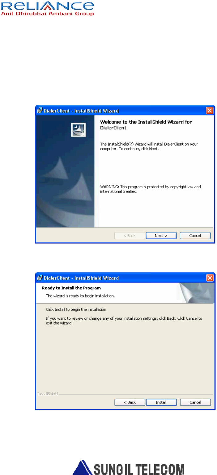
4. The picture is install start program screen . Click “Next”
5. The picture is ready to install the program. Click “Install”, start program
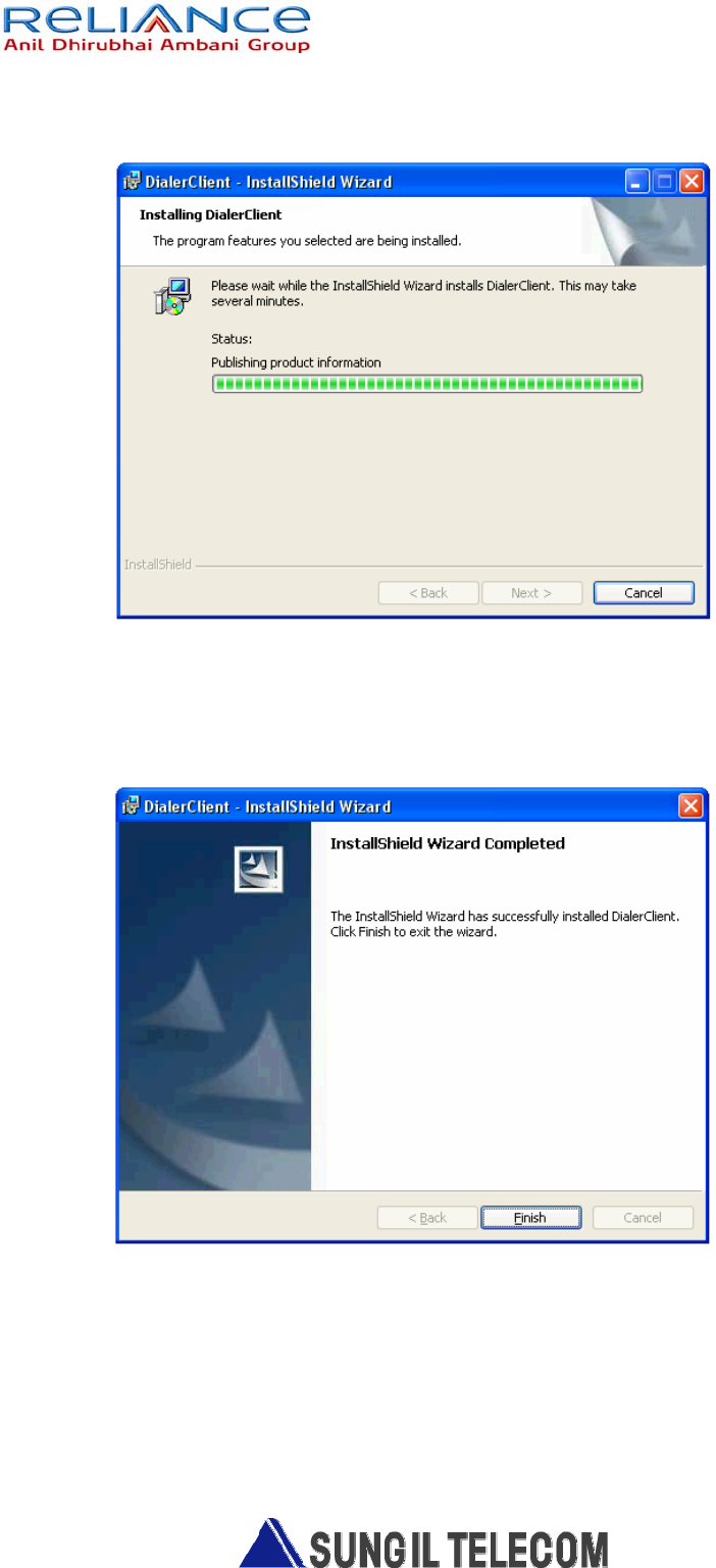
6. Start the Dialer Client install program
7. The picture is install program finished
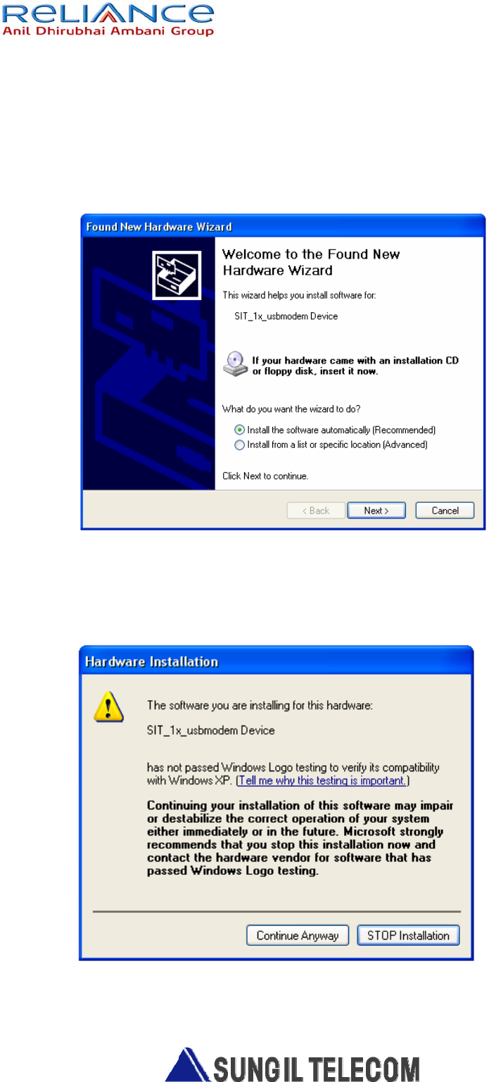
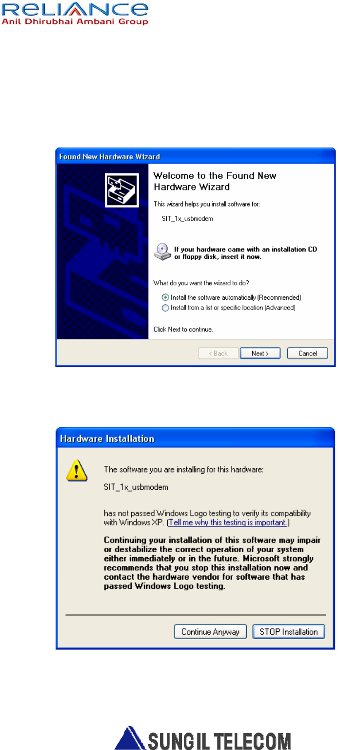
8-1. SIT_1x_usbmodem Device install(1).
- After installation process completing.
Connect the PC and the modem. And then the new hardware wizard is executed.
Click “Install the software automatically ” and “Next ”,
And then modem driver is installed automatically.
8-2. SIT_1x_usbmodem Device install(2).
. - Below window comes out to hardware installation process.
Then Click “continue Anyway”.
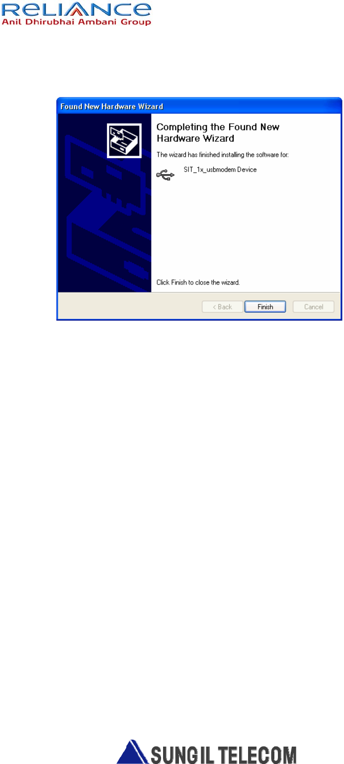
8-3. SIT_1x_usbmodem Device install (3).
- The picture is SIT_1x_usbmodem Device install finished.
9-1. SIT_1x_usbmodem install (1).
- After SIT_1x_usbmodem Device drive install finished.
The new hardware wizard is executed..
Click “Install the software automatically ” and “Next ”,
And then modem driver is installed automatically.
9-2. SIT _1x_usbmodem install (2).
- “Continue Anyway” Click

9-3. SIT _1x_usbmodem install(3).
- The picture is SIT_1x_usbmodem drive install finished.

10-1. SIT_1x_usbmodem Port install(1).
- After SIT_1x_usbmodem drive install finished.
The new hardware wizard is executed..
Click “Install the software automatically ” and “Next ”,
And then modem driver is installed automatically.
10-2. SIT_1x_usbmodem Port install(2).
- “Continue Anyway” Click.

10-3. SIT_1x_usbmodem Port install (3).
- The picture is SIT_1x_usbmodem Port install finished.
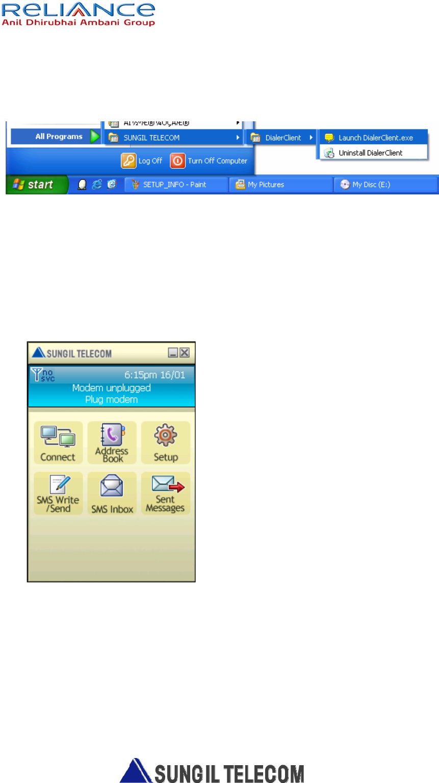
3-3. PC Client Manual
Run application and then below window is active.
Below window has 6 function menu.
1) Connect
Connect wireless internet via Dial connection network.
Click Connect menu to be showed below pop-up window
User name : fill in user ID, password and Dial number provided by service
provider, and then click connect button to connect wireless network.(If you
want to save this information, click square box next to “ Save setting”.
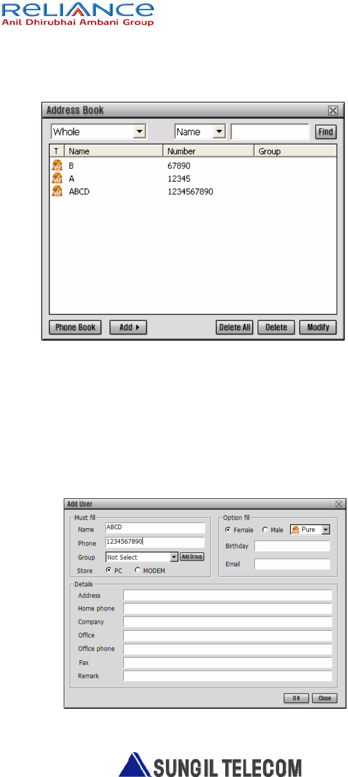
2) Address Book
- Manage phone book.
2.1) If you want to call or send SMS to member in the list, select the member
and click the right mouse button. You see pop-up menu and just click Send
or Call.
2.2) You can use Find function to find registered name or phone number you
want in the list.
2.3) If you want to register new number, just click Add button. You can see
“Add” list and Add Group. Select Add List to be showed new screen for new
Number. (Refer to below picture)
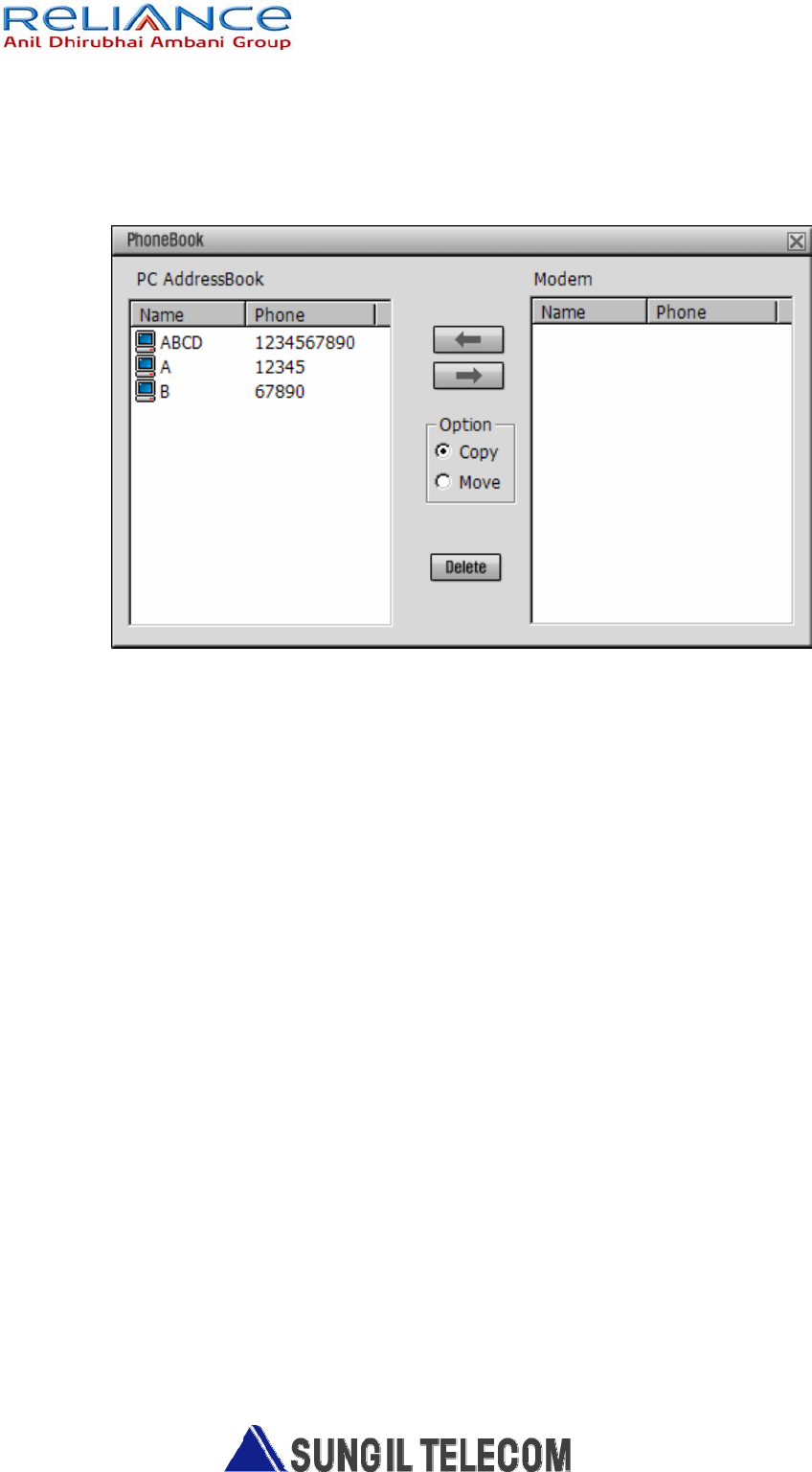
2.4) If you want to synchronize phone book between PC and Modem, click
“Phone Book” button to be showed below phone book window.
(Refer to below picture)
- Use left, right arrow button to select phone number and use copy/move
option to synchronize the selected number.
3) Setup
- Setup various information in application.
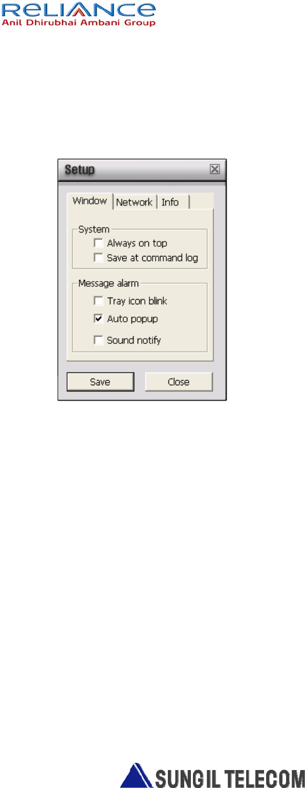
3.1) Window
Set up the window display function.
A) Always on top : Display window on top always.
B) Tray icon blink : When application receives messages, tray icon blinks
on working bar.
C) Auto Pop-up : when application receives messages, Message Box
window Shows automatically.
D) Sound prompt: when application receives messages, make arrival sound.
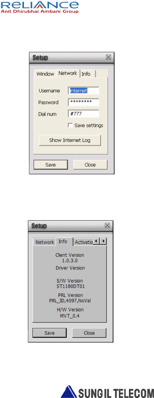
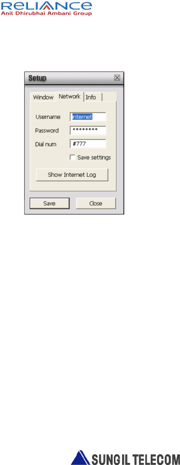
3.2) Network
- Register ID, password and Dial number to connect the wireless network.
3.3) Setup Info
- Show the application version.
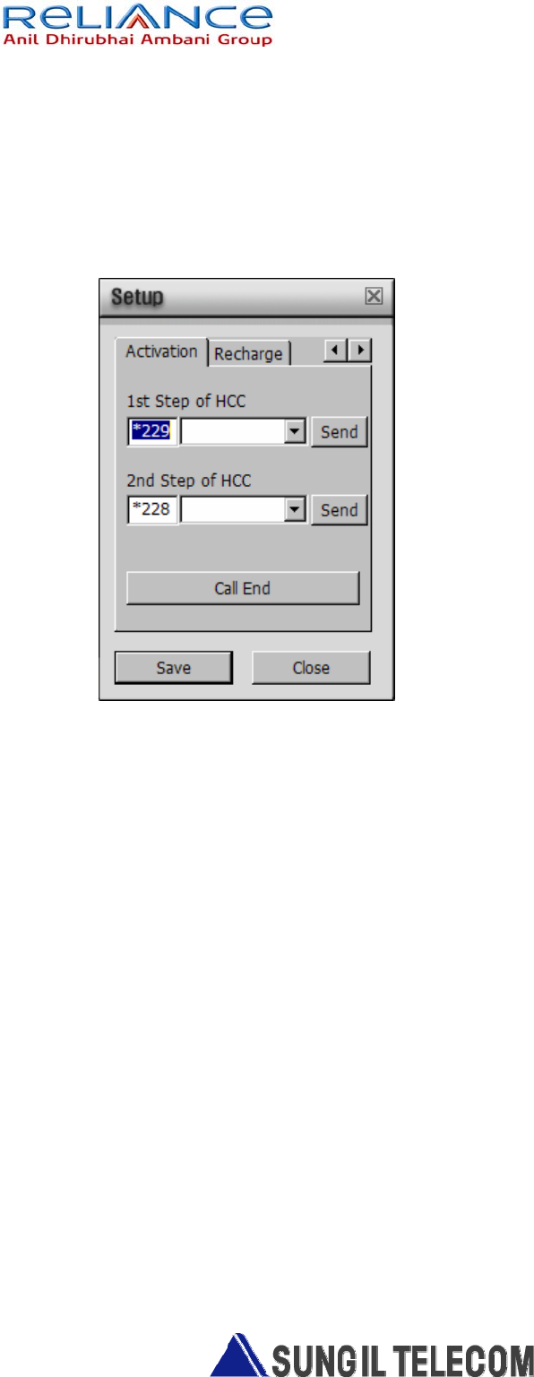
3.4) Activation
- Choose Activation tab of Setup menu.
- Press "Send" button after inputting the "1st HCC Number".
- "OK" message is displayed on the screen if succeed.
And then the "2nd Step" will be activated.
3.5) Recharge
- Choose Recharge tab of Setup menu.
- Press "Send" button after inputting the "PIN" Number.
- "OK" message is displayed on the screen if succeed.
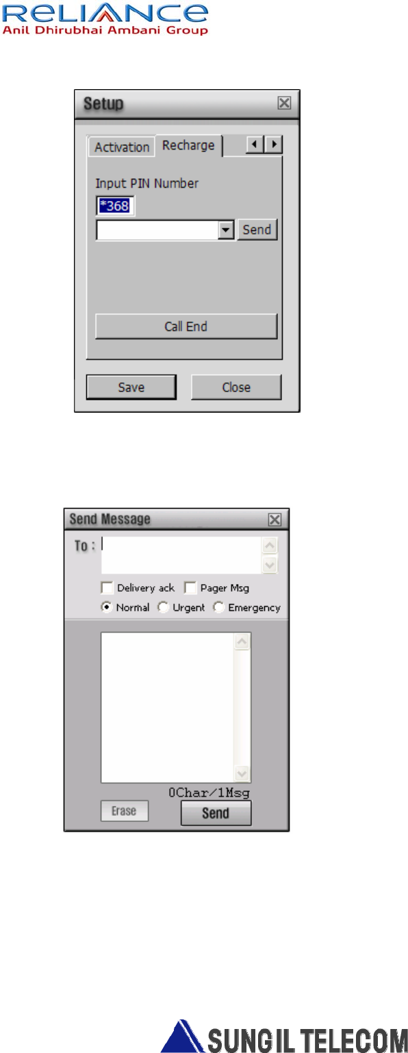
4) SMS Write/Send
Send SMS.
4.1) Fill in the number you want to send in blank box, “To : __________” and
click send button.
4.2) Delivery Ack : Ack Function enable.
4.3) To move to SMS manager screen, click the envelope button
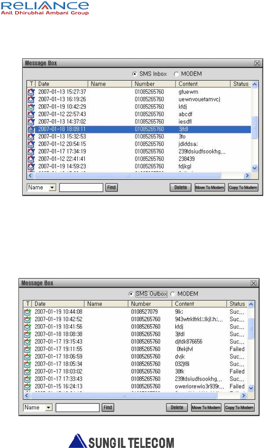
5) SMS Inbox
- Manage received and sent SMS history.
5.1) Select the number you want to send to and click right mouse button. You
see the SMS sending screen.
5.2) To copy SMS to Modem, Select the number you want to copy
and Click “ Copy to Modem” , To move Click “ Move to Modem.”
6) Sent Message
- Manage sent SMS. This is the same button with Sent Radio button in SMS Read

6.1) Select the number you want to forward to and click right mouse button.
You see the SMS sending screen.
6.2) To copy SMS to Modem, Select the number you want to copy
and Click “ Copy to Modem” , To move Click “ Move to Modem.”
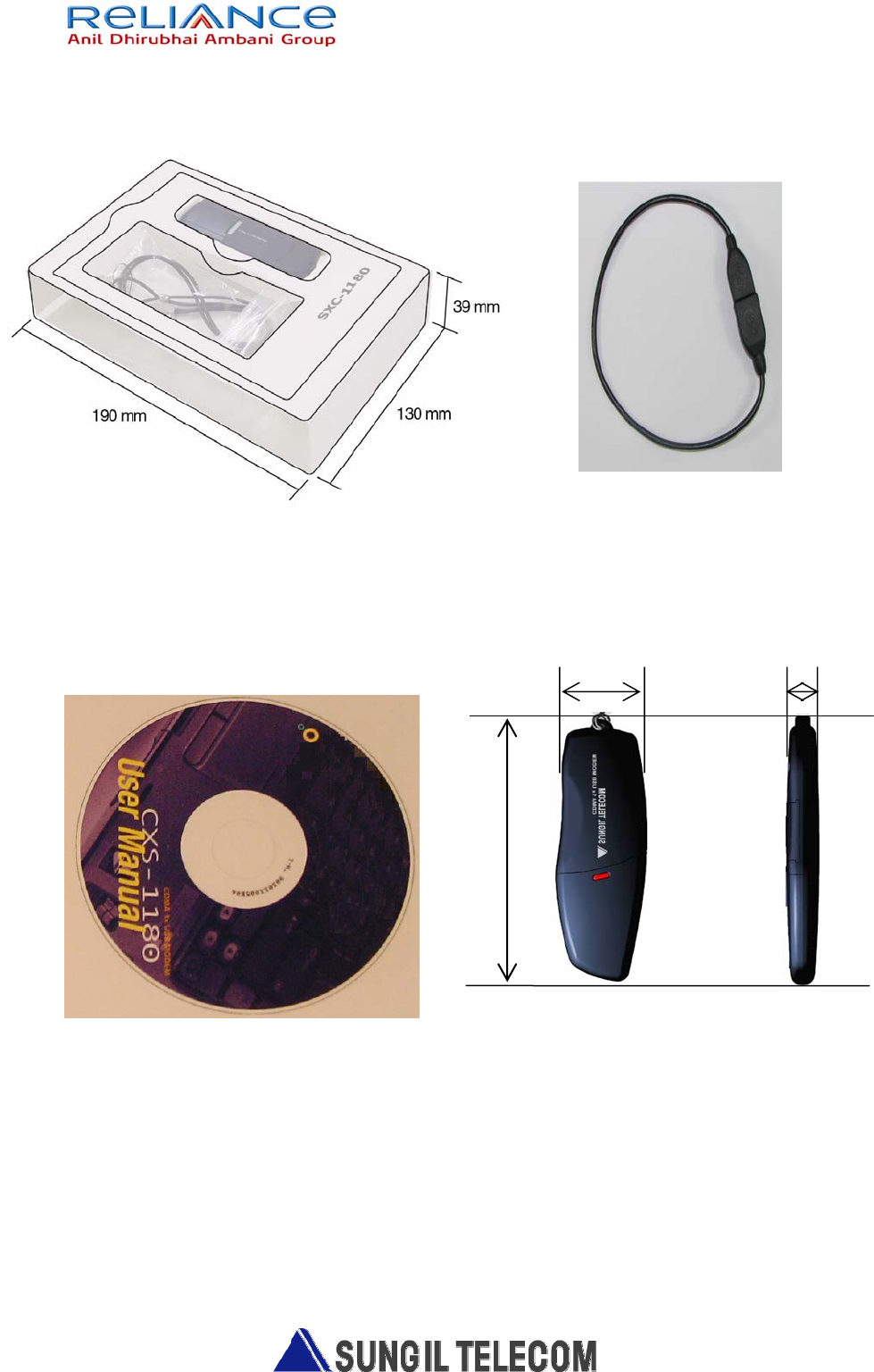
32mm
11.5mm
Figure 3.4 Mechanical dimension
94.4mm
4. Mechanical Specifications
Figure 3.1 Gift box Design Figure 3.2 USB Extension Cable
Figure 3.3 Install CD
RF EXPOSURE INFORMATION
THIS CDMA USB DONGLE MEETS THE GOVERNMENT ’S REQUIREMENTS FOR EXPOSURE TO RADIO WAVES.
Your CDMA USB DONGLE is a radio transmitter and receiver. It is designed and manufactured not to exceed the emission limits
for exposure to radio frequency (RF) energy set by the Federal Communications Commission of the U.S.Government. These limits
are part of comprehensive guidelines and establish permitted levels of RF energy for the general population. The guidelines are
based on standards that were developed by independent scientific organizations through periodic and thorough evaluate on of
scientific studies. The standards include a substantial safety margin designed to assure the safety of all persons, regardless of age
and health.
The exposure standard for wireless devices employs a unit of measurement known as the Specific Absorption Rate, or SAR. The
SAR limit set by the FCC is 1.6 W/kg.*Tests for SAR are conducted with the device transmitting at its highest certified power level
in all tested frequency bands. Although the SAR is determined at the highest certified power level, the actual SAR level of the
device while operating can be well below the maximum value. This is because the phone is designed to operate at multiple power
levels so as to use only the power required to reach the network. In general, the closer you are to a wireless base station antenna, the
lower the power output. Before a wireless device is available for sale to the public, it must be tested and certified to the FCC that it
does not exceed the limit established by the government adopted requirement for safe exposure.
The highest SAR value for this CDMA USB Dongle is 1.230 W/kg. The FCC has granted an Equipment Authorization for this
CDMA USB Dongle with all reported SAR levels evaluated as in compliance with the FCC RF exposure guidelines. SAR
information on this model phone is on file with the FCC and can be found under the Display Grant section of http://www.fcc.gov /
oet / fcc id after searching on FCC ID : R2NSXC-1180.
Additional information on Specific Absorption Rates (SAR)can be found on the Cellular Telecommunications &Internet Association
(CTIA) web-site at http://phonefacts.net.*In the United States and Canada, the SAR limit for mobile phones used by the public is
1.6watts/kg (W/kg)averaged over one gram of tissue. The standard incorporates a substantial margin of safety to give additional
protection for the public and to account for any agitations in measurements.
In August 1996 the Federal Communications Commission (FCC) of the United States with its action in Report and Order FCC 96-
326 adopted an updated safety standard for human exposure to radio frequency (RF) electromagnetic energy emitted by FCC
regulated transmitters. Those guidelines are consistent with the safety standard previously set by both U.S. and international
standards bodies. The design of this phone complies with the FCC guidelines and these international standards.
For more information about RF exposure, please visit the FCC website at www.fcc.gov
WARNING! Read this information before use
Caution
Modifications not expressly approved by the party responsible for compliance could void the user’s authority to operate the
equipment.
FCC Compliance Information
This device complies with Part 15 of FCC Rules. Operation is subject to the following two conditions: (1) This device may not
cause harmful interference, and (2) This device must accept any interference received. Including interference that may cause
undesired operation.
Information to User
This equipment has been tested and found to comply with the limits for a Class B digital device, pursuant to part 15 of the FCC
Rules. These limits are designed to provide reasonable protection against harmful interference in a residential installation. This
equipment generates, uses and can radiate radio frequency energy and, if not installed and used in accordance with the instructions,
may cause harmful interference to radio communications. However, there is no guarantee that interference will not occur in a
particular installation. If this equipment does cause harmful interference to radio or television reception, which can be determined by
turning the equipment off and on, the user is encouraged to try to correct the interference by one or more of the following measures:
- Reorient or relocate the receiving antenna.- Increase the separation between the equipment and receiver.
- Connect the equipment into an outlet on a circuit different from that to which the receiver is connected.
- Consult the dealer or an experienced radio/ tv technician for help.
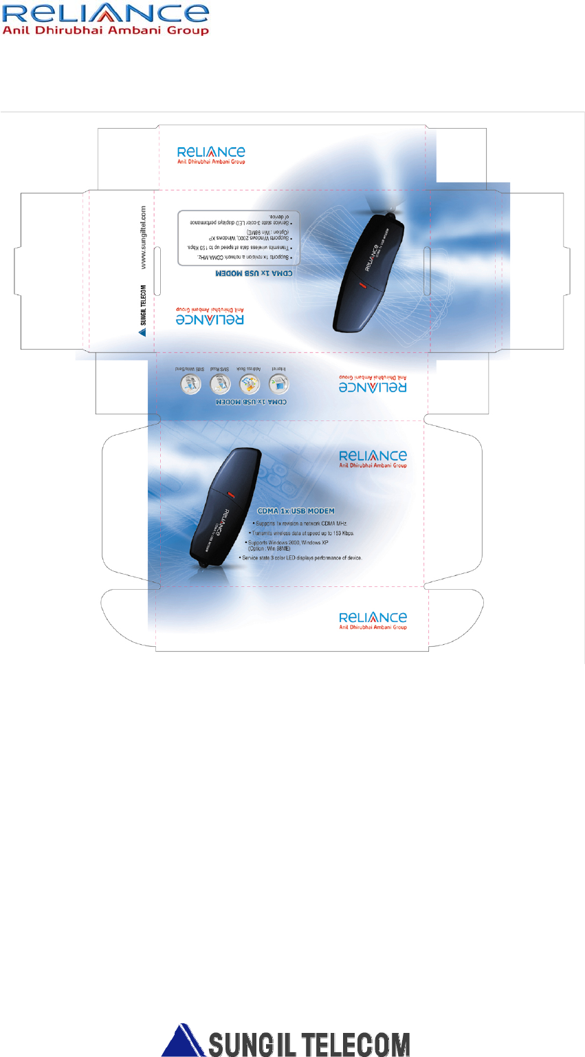
Figure 3.5 Gift box Design