Epson G3 Series Users Manual ROBOT
G3 Series to the manual c10626c8-42d6-407b-9a33-e30dac6049e0
2015-01-23
: Epson Epson-G3-Series-Users-Manual-252124 epson-g3-series-users-manual-252124 epson pdf
Open the PDF directly: View PDF ![]() .
.
Page Count: 92
- EM08ZR1795F SCARA ROBOTG3 series MANIPULATOR MANUAL
Rev.1
- PREFACE
- TABLE OF CONTENTS
- Setup & Operation
- 1. Safety
- 2. Specifications
- 3. Environments and Installation
- 4. Setting of End Effectors
- 4.1 Attaching an End Effector
- 4.2 Attaching Cameras and Valves
- 4.3 Weight and Inertia Settings
- 4.3.1 Weight Setting
- 4.3.2 Inertia Setting
- Moment of Inertia and the Inertia Setting
- Moment of inertia of load on the shaft
- Automatic acceleration/deceleration setting of Joint #4 by Inertia (moment of inertia)
- Eccentric Quantity and the Inertia Setting
- Eccentric quantity of load on the shaft
- Automatic acceleration/deceleration setting by Inertia (eccentric quantity)
- Calculating the Moment of Inertia
- 4.4 Precautions for Auto Acceleration/Deceleration of Joint #3
- 5. Motion Range
- Maintenance

SCARA ROBOT
G3 series
MANIPULATOR MANUAL
Rev.1 EM08ZR1795F
MANIPULATOR MANUAL G3 series Rev.1

G3 Rev.1 i
SCARA ROBOT
G3 series Manipulator Manual
Rev.1
Copyright © 2008 SEIKO EPSON CORPORATION. All rights reserved.
ii G3 Rev.1
FOREWORD
Thank you for purchasing our robot products.
This manual contains the information necessary for the correct use of the manipulator.
Please carefully read this manual and other related manuals before installing the robot
system.
Keep this manual handy for easy access at all times.
WARRANTY
The Manipulator and its optional parts are shipped to our customers only after being
subjected to the strictest quality controls, tests, and inspections to certify its compliance
with our high performance standards.
Product malfunctions resulting from normal handling or operation will be repaired free of
charge during the normal warranty period. (Please ask your Regional Sales Office for
warranty period information.)
However, customers will be charged for repairs in the following cases (even if they occur
during the warranty period):
1. Damage or malfunction caused by improper use which is not described in the manual,
or careless use.
2. Malfunctions caused by customers’ unauthorized disassembly.
3. Damage due to improper adjustments or unauthorized repair attempts.
4. Damage caused by natural disasters such as earthquake, flood, etc.
Warnings, Cautions, Usage:
1. If the Manipulator or associated equipment is used outside of the usage conditions an
d
product specifications described in the manuals, this warranty is void.
2. If you do not follow the WARNINGS and CAUTIONS in this manual, we cannot be
responsible for any malfunction or accident, even if the result is injury or death.
3. We cannot foresee all possible dangers and consequences. Therefore, this manual
cannot warn the user of all possible hazards.

G3 Rev.1 iii
TRADEMARKS
Microsoft, Windows, and Windows logo are either registered trademarks or trademarks of
Microsoft Corporation in the United States and/or other countries. Other brand and
product names are trademarks or registered trademarks of the respective holders.
NOTICE
No part of this manual may be copied or reproduced without authorization.
The contents of this manual are subject to change without notice.
Please notify us if you should find any errors in this manual or if you have any comments
regarding its contents.
INQUIRIES
Contact the following service center for robot repairs, inspections or adjustments.
If service center information is not indicated below, please contact the supplier office for
your region.
Please prepare the following items before you contact us.
- Your controller model and its serial number
- Your manipulator model and its serial number
- Software and its version in your robot system
- A description of the problem
SERVICE CENTER
iv G3 Rev.1
MANUFACTURER & SUPPLIER
SEIKO EPSON CORPORATION
Japan & Others
Suwa Minami Plant
Factory Automation Systems Dept.
1010 Fujimi, Fujimi-machi,
Suwa-gun, Nagano, 399-0295
JAPAN
TEL : +81-(0)266-61-1802
FAX : +81-(0)266-61-1846
SUPPLIERS
North & South America EPSON AMERICA, INC.
Factory Automation/Robotics
18300 Central Avenue
Carson, CA 90746
USA
TEL : +1-562-290-5900
FAX : +1-562-290-5999
E-MAIL : info@robots.epson.com
Europe EPSON DEUTSCHLAND GmbH
Factory Automation Division
Otto-Hahn-Str.4
D-40670 Meerbusch
Germany
TEL : +49-(0)-2159-538-1391
FAX : +49-(0)-2159-538-3170
E-MAIL : robot.infos@epson.de

G3 Rev.1 v
Before Reading This Manual
This section describes what you should know before reading this manual.
Structure of Control System
The G3 series Manipulators can be used with the following combinations of Controllers and
software.
The operating methods and descriptions are different depending on which software you are
using. The following icons are put beside appropriate text as necessary. Use the
descriptions that pertain to the software you are using.
Controller : RC180
Software : EPSON RC+ 5.0 Ver. 5.3 or greater
For details on commands, refer to User’s Guide or “On-line help”.
Turning ON/OFF Controller
When you see the instruction “Turn ON/OFF the Controller” in this manual, be sure to
turn ON/OFF all the hardware components. For the Controller composition, refer to the
table above.
Shape of Motors
The shape of the motors used for the Manipulator that you are using may be different from
the shape of the motors described in this manual because of the specifications.
Setting by Using Software
This manual contains setting procedures by using software. They are marked with the
following icon.
EPSON
RC+
Figures in this Manual
The figures of manipulators indicated in this manual are basically Standard-model
Manipulator. Unless special instruction is provided, the specifications of Standard-model
and Cleanroom-model are the same.
vi G3 Rev.1

G3 Rev.1 vii
TABLE OF CONTENTS
Before Reading This Manual ................................................................................... v
Setup & Operation
1. Safety 3
1.1 Conventions.............................................................................................3
1.2 Design and Installation Safety .................................................................4
1.3 Operation Safety......................................................................................5
1.4 Emergency Stop ......................................................................................6
1.5 Emergency Movement Without Drive Power ...........................................7
1.6 Manipulator Labels ..................................................................................8
2. Specifications 10
2.1 Features of G3 series Manipulators.......................................................10
2.2 Model Number and Model Differences ..................................................11
2.3 Part Names and Outer Dimensions .......................................................12
2.3.1 Table Top Mounting ....................................................................12
2.3.2 Multiple Mounting.......................................................................16
2.4 Specifications.........................................................................................20
2.5 How to Set the Model ............................................................................22
3. Environments and Installation 23
3.1 Environmental Conditions......................................................................23
3.2 Base Table.............................................................................................24
3.3 Mounting Dimensions ............................................................................25
3.4 Unpacking and Transportation ...............................................................28
3.5 Installation Procedure ............................................................................29
3.5.1 Table Top Mounting ....................................................................29
3.5.2 Multiple Mounting.......................................................................30
3.5.3 Cleanroom-model ......................................................................31
3.6 Connecting the Cables ..........................................................................31
3.7 User Wires and Pneumatic Tubes .........................................................33
3.8 Relocation and Storage .........................................................................35
3.8.1 Precautions for Relocation and Storage.....................................35
3.8.2 Table Top Mounting ....................................................................36
3.8.3 Multiple Mounting.......................................................................37
4. Setting of End Effectors 38
4.1 Attaching an End Effector ......................................................................38
4.2 Attaching Cameras and Valves..............................................................39
4.3 Weight and Inertia Settings....................................................................40
4.3.1 Weight Setting............................................................................40
4.3.2 Inertia Setting.............................................................................42
4.4 Precautions for Auto Acceleration/Deceleration of Joint #3 ...................45

TABLE OF CONTENTS
viii G3 Rev.1
5. Motion Range 46
5.1 Motion Range Setting by Pulse Range (for All Joints)........................... 47
5.1.1 Max. Pulse Range of Joint #1.................................................... 48
5.1.2 Max. Pulse Range of Joint #2.................................................... 49
5.1.3 Max. Pulse Range of Joint #3.................................................... 50
5.1.4 Max. Pulse Range of Joint #4.................................................... 50
5.2 Motion Range Setting by Mechanical Stops.......................................... 51
5.2.1 Setting the Mechanical Stops of Joints #1 and #2 ..................... 52
5.2.2 Setting the Mechanical Stop of Joint #3..................................... 55
5.3 Setting the Cartesian (Rectangular) Range in the XY Coordinate
System of the Manipulator (for Joints #1 and #2)................................ 57
5.4 Standard Motion Range ........................................................................ 57
Maintenance
1. Safety Maintenance 67
2. General Maintenance 68
2.1 Schedule for Maintenance Inspection ................................................... 68
2.2 Inspection Point..................................................................................... 69
2.2.1 Inspection While the Power is OFF
(Manipulator is not operating).................................................... 69
2.2.2 Inspection While the Power is ON
(Manipulator is operating).......................................................... 69
2.3 Greasing ............................................................................................... 70
2.4 Tightening Hexagon Socket Head Cap Bolts ........................................ 71
2.5 Matching Origins ................................................................................... 71
2.6 Layout of Maintenance Parts................................................................. 72
2.6.1 Table Top Mounting ................................................................... 72
2.6.2 Multiple Mounting ...................................................................... 73
3. Covers 74
3.1 Arm Top Cover ...................................................................................... 75
3.2 Arm Bottom Cover................................................................................. 77
3.3 Arm Cap................................................................................................ 77
3.4 Connector Plate .................................................................................... 78
3.5 Connector Sub Plate ............................................................................. 79
3.6 User Plate ............................................................................................. 79
3.7 Maintenance Plate ................................................................................ 80
3.8 Base Bottom Cover ............................................................................... 80
4. Maintenance Parts List 81
4.1 Common Parts ...................................................................................... 81
4.2 Parts by Environment Model ................................................................. 81
4.2.1 S: Standard-model .................................................................... 82
4.2.2 C: Cleanroom-model ................................................................. 82

Setup & Operation
This volume contains information for setup and operation of the
G3 series Manipulators.
Please read this volume thoroughly before setting up and
operating the Manipulators.
Setup & Operation 1. Safety
G3 Rev.1 3
1. Safety
Installation and transportation of robots and robotic equipment shall be performed by
qualified personnel and should conform to all national and local codes. Please read this
manual and other related manuals before installing the robot system or before connecting
cables.
Keep this manual handy for easy access at all times.
1.1 Conventions
Important safety considerations are indicated throughout the manual by the following
symbols. Be sure to read the descriptions shown with each symbol.
WARNING
This symbol indicates that a danger of possible serious injury
or death exists if the associated instructions are not followed
properly.
WARNING
This symbol indicates that a danger of possible serious injury
or death caused by electric shock exists if the associated
instructions are not followed properly.
CAUTION
This symbol indicates that a danger of possible harm to
people or physical damage to equipment and facilities exists if
the associated instructions are not followed properly.
Setup & Operation 1. Safety
1.2 Design and Installation Safety
Only trained personnel should design and install the robot system. Trained
personnel are defined as those who have taken robot system training and
maintenance training classes held by the manufacturer, dealer, or local
representative company, or those who understand the manuals thoroughly and
have the same knowledge and skill level as those who have completed the training
courses.
To ensure safety, a safeguard must be installed for the robot system. For details
on the safeguard, refer to the Installation and Design Precautions in the Safety
chapter of the EPSON RC+ User’s Guide.
The following items are safety precautions for design personnel:
■ Personnel who design and/or construct the robot system with this product must
read the Safety chapter in the EPSON RC+ User’s Guide to understand the
safety requirements before designing and/or constructing the robot system.
Designing and/or constructing the robot system without understanding the safety
requirements is extremely hazardous, may result in serious bodily injury and/or
severe equipment damage to the robot system, and may cause serious safety
problems.
■ The Manipulator and the Controller must be used within the environmental
conditions described in their respective manuals. This product has been
designed and manufactured strictly for use in a normal indoor environment.
Using the product in an environment that exceeds the specified environmental
conditions may not only shorten the life cycle of the product but may also cause
serious safety problems.
WARNING
■ The robot system must be used within the installation requirements described in
the manuals. Using the robot system outside of the installation requirements
may not only shorten the life cycle of the product but also cause serious safety
problems.
Further precautions for installation are mentioned in the chapter Setup &
Operation: 3. Environments and Installation. Please read this chapter carefully to
understand safe installation procedures before installing the robots and robotic
equipment.
4 G3 Rev.1
Setup & Operation 1. Safety
1.3 Operation Safety
The following items are safety precautions for qualified Operator personnel:
■ Please carefully read the Safety-related Requirements in the Safety chapter of
the EPSON RC+ User’s Guide before operating the robot system. Operating
the robot system without understanding the safety requirements is extremely
hazardous and may result in serious bodily injury and/or severe equipment
damage to the robot system.
■ Do not enter the operating area of the Manipulator while the power to the robot
system is turned ON. Entering the operating area with the power ON is
extremely hazardous and may cause serious safety problems as the Manipulator
may move even if it seems to be stopped.
■ Before operating the robot system, make sure that no one is inside the
safeguarded area. The robot system can be operated in the mode for teaching
even when someone is inside the safeguarded area.
The motion of the Manipulator is always in restricted (low speeds and low power)
status to secure the safety of an operator. However, operating the robot system
while someone is inside the safeguarded area is extremely hazardous and may
result in serious safety problems in case that the Manipulator moves
unexpectedly.
WARNING
■ Immediately press the Emergency Stop switch whenever the Manipulator moves
abnormally while the robot system is operated.
■ To shut off power to the robot system, pull out the power plug from the power
source. Be sure to connect the AC power cable to a power receptacle. DO
NOT connect it directly to a factory power source.
■ Before performing any replacement procedure, turn OFF the Controller and
related equipment, and then pull out the power plug from the power source.
Performing any replacement procedure with the power ON is extremely
hazardous and may result in electric shock and/or malfunction of the robot
system.
WARNING
■ Do not insert or pull out the motor connectors while the power to the robot system
is turned ON. Inserting or pulling out the motor connectors with the power ON is
extremely hazardous and may result in serious bodily injury as the Manipulator
may move abnormally, and also may result in electric shock and/or malfunction of
the robot system.
CAUTION
■ Whenever possible, only one person should operate the robot system. If it is
necessary to operate the robot system with more than one person, ensure that all
people involved communicate with each other as to what they are doing and take
all necessary safety precautions.
G3 Rev.1 5
Setup & Operation 1. Safety
1.4 Emergency Stop
If the Manipulator moves abnormally during operation, immediately press the Emergency
Stop switch. Stops the power supply to the motor, and the arm stops in the shortest
distance with the dynamic brake and mechanical brake.
However, avoid pressing the Emergency Stop switch unnecessarily while the Manipulator
is running normally. Otherwise, the Manipulator may hit the peripheral equipment since
the operating trajectory while the robot system stops is different from that in normal
operation.
To place the system in emergency mode during normal operation, press the Emergency
Stop switch when the Manipulator is not moving.
Refer to the Controller manual for instructions on how to wire the Emergency Stop switch
circuit.
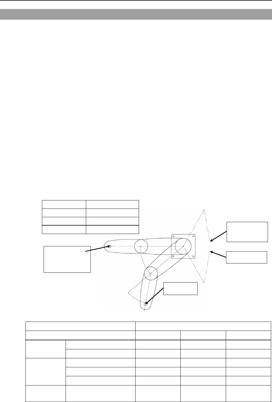
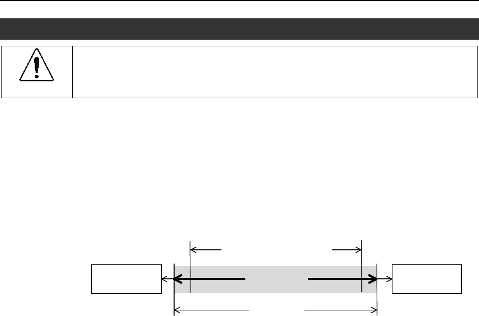
Free running distance in emergency
The operating Manipulator cannot stop immediately after the Emergency Stop switch is
pressed.
The free running time/angle/distance of the Manipulator are shown below. However,
remember that the values vary depending on following conditions.
Weight of the end effector Weight of work piece Operating pose
Weight Speed Accel etc.
Conditions for Measurement
Accel Setting 100
Speed Setting 100
Load [kg] 3
Weight Setting 3
Joint #1
Point where the
emergency stop
signal is input
Start point of
operation
Target point
Stop point
Joint #2
Controller RC180
Manipulator G3-25*** G3-30*** G3-35***
Joint #1 + Joint #2 [sec.] 0.8 1.2 0.6
Free running
time Joint #3 [sec.] 0.6 0.6 0.6
Joint #1 [deg.] 41 53 57
Joint #2 [deg.] 13 20 20
Free running
angle
Joint #1 + Joint #2 [deg.] 54 73 77
Free running
distance Joint #3 G3-**1** [mm] 95 95 95
6 G3 Rev.1
Setup & Operation 1. Safety
G3 Rev.1 7
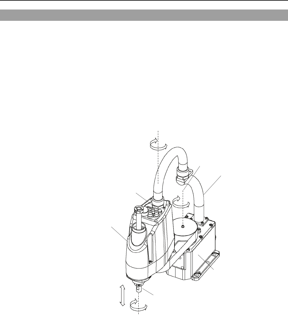
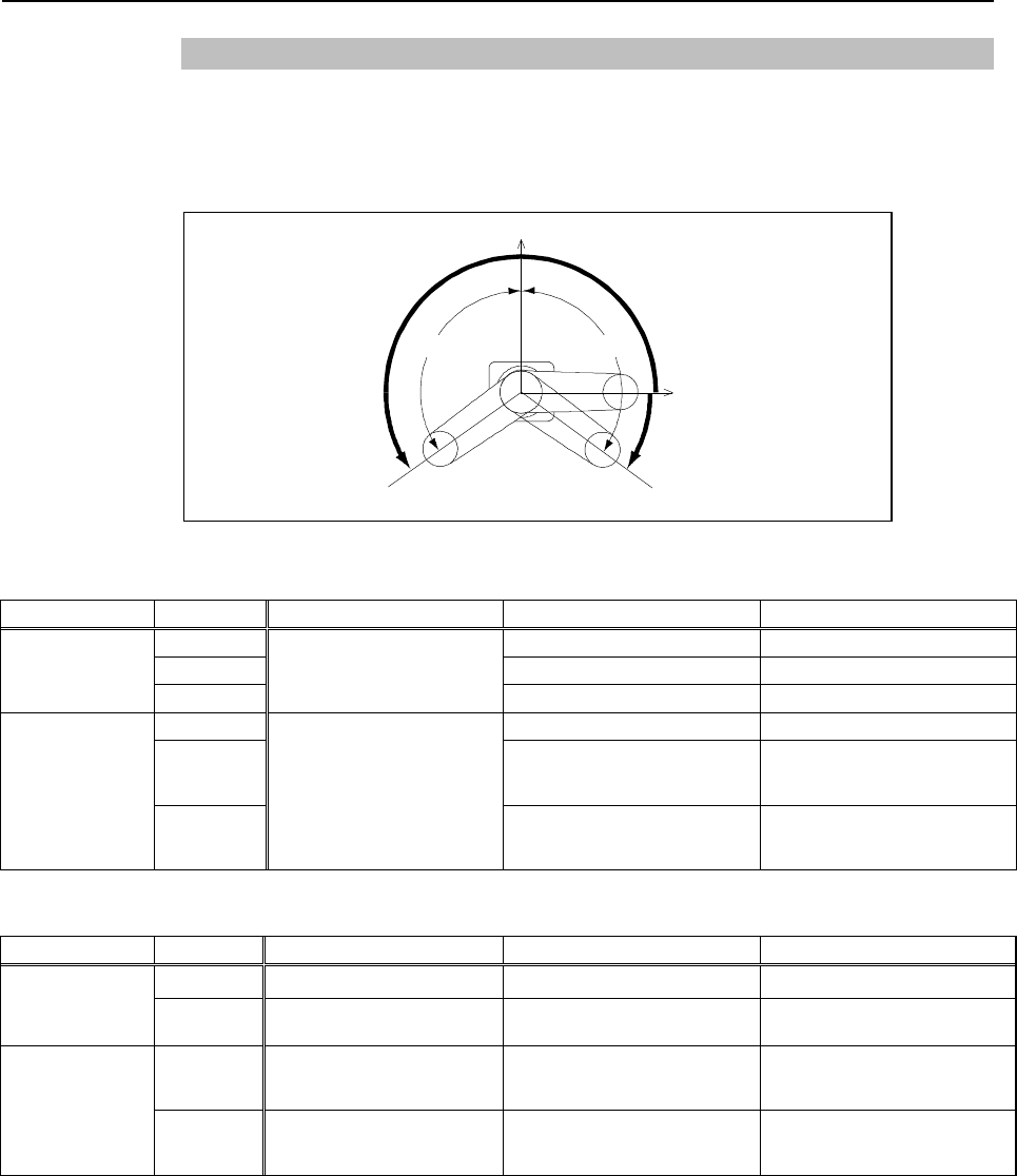
1.5 Emergency Movement Without Drive Power
When the system is placed in emergency mode, push the arm or joint of the
Manipulator by hand as shown below:
Arm #1 ............. Push the arm by hand.
Arm #2 ............. Push the arm by hand.
Joint #3 ............ The joint cannot be moved up/down by hand until the
electromagnetic brake applied to the joint has been released.
Move the joint up/down while pressing the brake release button
switch.
Joint #4........... Rotate the shaft by hand.
+
−
+
−
+
−
+
−
Joint #3 and #4
brake release button
Joint #1
(rotating)
Joint #2
(rotating)
Joint #3
(up and down)
Joint #4
(rotating)
Arm #1
Arm #2
Base
Shaft
The brake release button affects only Joint #3. When the brake release button is
pressed in emergency mode, the brake for Joint #3 is released simultaneously.
)
NOTE
Be careful of the shaft while the brake release button is pressed because the shaft may
be lowered by the weight of an end effector.

Setup & Operation 1. Safety
1.6 Manipulator Labels
The following labels are attached near the locations of the Manipulator where specific
dangers exist.
Be sure to comply with descriptions and warnings on the labels to operate and maintain
the Manipulator safely.
Do not tear, damage, or remove the labels. Use meticulous care when handling those
parts or units to which the following labels are attached as well as the nearby areas:
Labels NOTE
A
Before loosening the base mounting
screws, hold the arm and secure it tightly
with a band to prevent hands or fingers
from being caught in the Manipulator.
B
C
Hazardous voltage exists while the
Manipulator is ON. To avoid electric
shock, do not touch any internal electric
parts.
D
You can catch your hand or fingers
between the shaft and cover when
bringing your hand close to moving parts.
E
HOT
Be careful not to burn yourself.
8 G3 Rev.1
Setup & Operation 1. Safety
G3 Rev.1 9
A
B
D
C
Common
Table Top Mounting
Multiple Mounting
C
E
C
A
B
E
Manipulators with bellows do not have label D.
Because they have no risk of catching your hand or fingers.
)
NOTE

Setup & Operation 2. Specifications
10 G3 Rev.1
2. Specifications
2.1 Features of G3 series Manipulators
The G3 series Manipulators are high-performance manipulators pursuing high speed, high
accuracy, space saving, and high cost-performance.
The features of the G3 series Manipulators are as follows:
Space productivity
Top level of cycle time and positioning accuracy
Minimized body
10 % downsize of overall height in the rank
Extended motion range
The same size of motion range compared with the other brands’ one up robots
Extended range in Z direction
Obtain the stroke under the body
Succeeded E2C series advantages
Compatibility with the E2 series Manipulators
The installation procedure and mounting dimensions of end effector for the G3 series
are compatible with those for E2 series
* Secure the compatible mounting position with optional parts
Improved productivity
Increase in number of user wires and pneumatic tubes
Enhanced speed of Joint #1, 2, 3, and 4
Improved cycle time
Setup & Operation 2. Specifications
G3 Rev.1 11
2.2 Model Number and Model Differences
G3-25 1 S □-R-UL
Fire resistant
□: No fire resistant
UL : UL compliance
Type
□: Standard
R : Right-Curved
L : Left-Curved
Environment
S : Standard
C : Cleanroom & ESD (Anti-Static)
Joint #3 stroke
: 150 mm
1: 120 mm (Cleanroom-model)
Arm length
25 : 250 mm
30 : 300 mm
35 : 350 mm
Mounting type
□: Table Top Mounting
M : Multiple Mounting
Environment
Cleanroom-model
This model has additional features that reduce dust emitted by the Manipulator to enable
use in clean room environments.
For details on the specifications, refer to Setup & Operation: 2.4 Specifications.
Setup & Operation 2. Specifications
12 G3 Rev.1
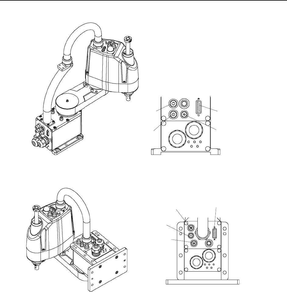
2.3 Part Names and Outer Dimensions
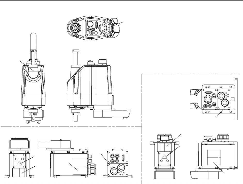
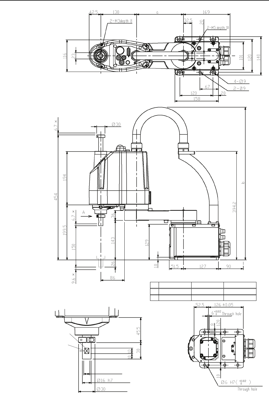
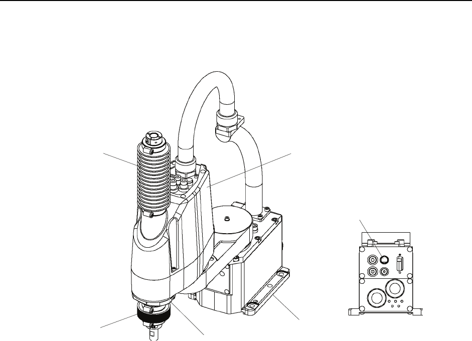
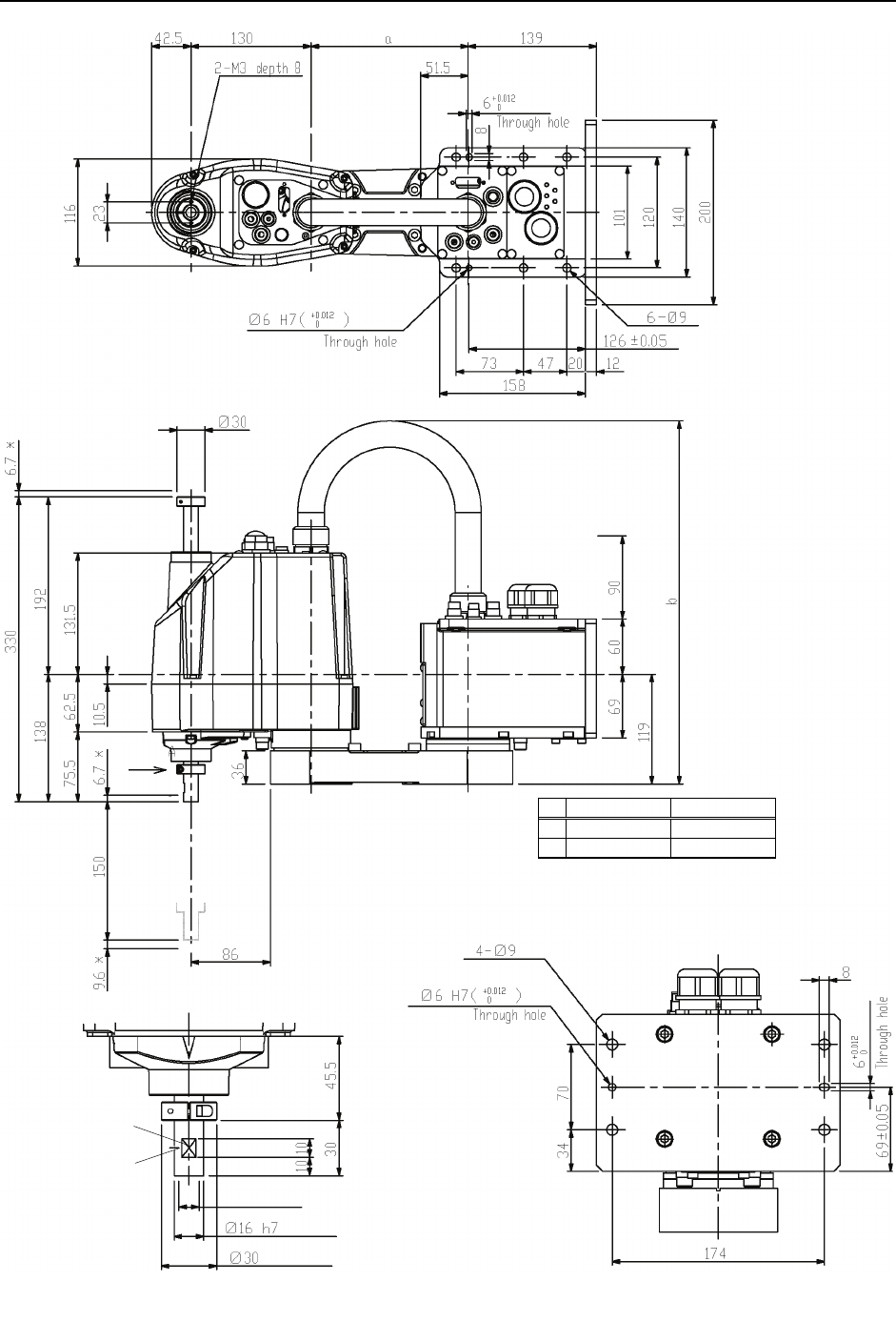
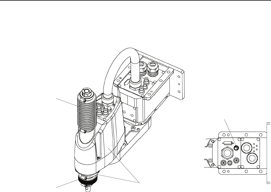
2.3.1 Table Top Mounting
Standard-model G3-***S
CE label
+
−
+
−
+
−
+
−
UR label
Joint #3 / #4
Brake release switch
Joint #1
(rotating)
Joint #2
(rotating)
Joint #3
(Up/Down)
Joint #4
(rotating)
Arm #1
Arm #2
Base
Shaft
MT label (only for special order)
Face plate (Manipulator serial No.)
Signal cable
Power cable
Fitting (black)
for ø4 mm
pneumatic tube
Fittings (black)
for ø6 mm
pneumatic tube
Fittings (white)
for ø6 mm
pneumatic tube
User connector
(15-pin D-sub connector)
)
NOTE The brake release button affects only Joint #3. When the brake release button is pressed in
emergency mode, the brake for Joint #3 is released simultaneously.
Setup & Operation 2. Specifications
G3 Rev.1 13
shaft diameter
G3-251*S G3-301*S G3-351*S
a 120 170 220
b Max.545 Max.575 Max.595
Max.ø11 through hole
mechanical stop diameter
Conical hole
Ø3,90°
1 mm flat cut
Detail of “A”
(
Calibration point position of Joints #3 and #4
)
or more
Space for cables
(*) indicates the stroke margin
by mechanical stop.
Reference through hole
(
View from the bottom of the base
)
Setup & Operation 2. Specifications
14 G3 Rev.1
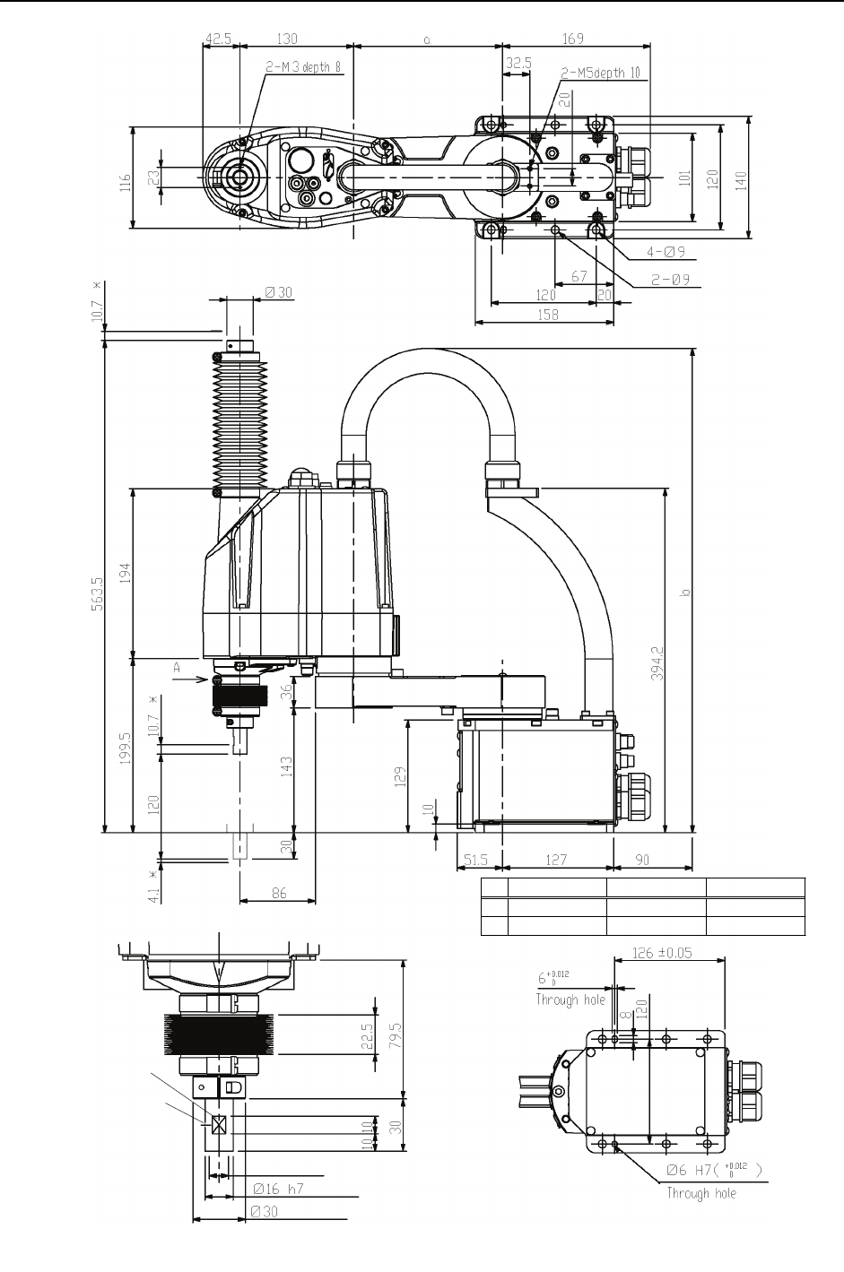
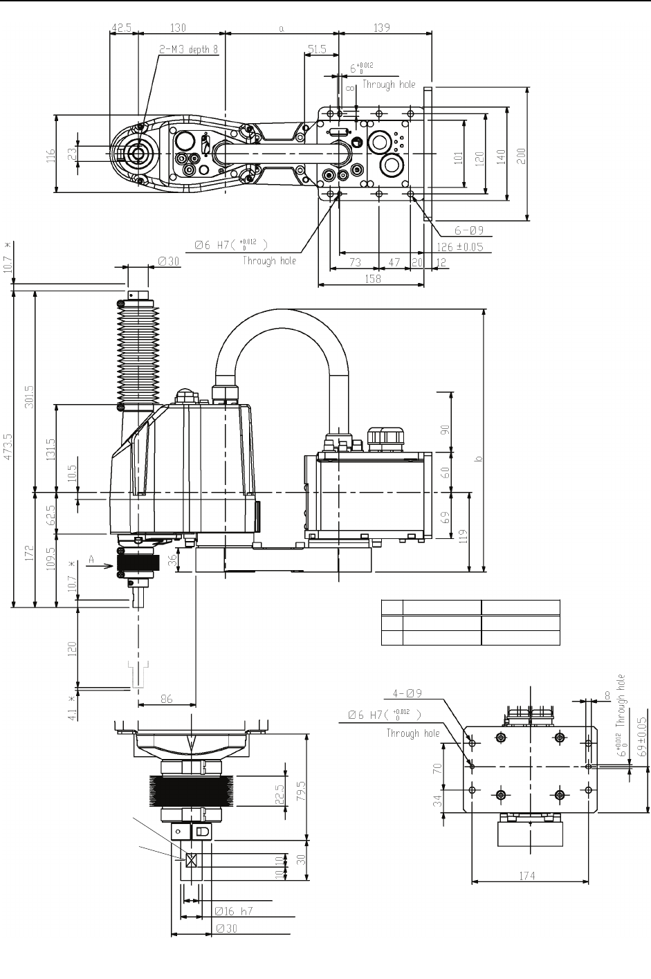
Cleanroom-model: G3-***C
The following figures show the additional parts and specifications for Cleanroom-model (Table Top mounting)
when compared with the Standard-model in appearance.
Upper bellows
Plate cover
(For Anti-static)
Cover
for Table Top mounting surface
Exhaust port
Lower bellows
Plate cover
(For Anti-static)
Setup & Operation 2. Specifications
G3 Rev.1 15
G3-251*S G3-301*S G3-351*S
a 120 170 220
b Max.545 Max.575 Max.595
shaft diameter
Max.ø11 through hole
mechanical stop diameter
Conical hole
Ø3,90°
1 mm flat cut
Detail of “A”
(
Calibration point position of Joints #3 and #4
)
S
p
ace for cables
(*) indicates the stroke margin by mechanical stop.
Reference through hole
(View from the bottom of the base)
or
more
Setup & Operation 2. Specifications
16 G3 Rev.1
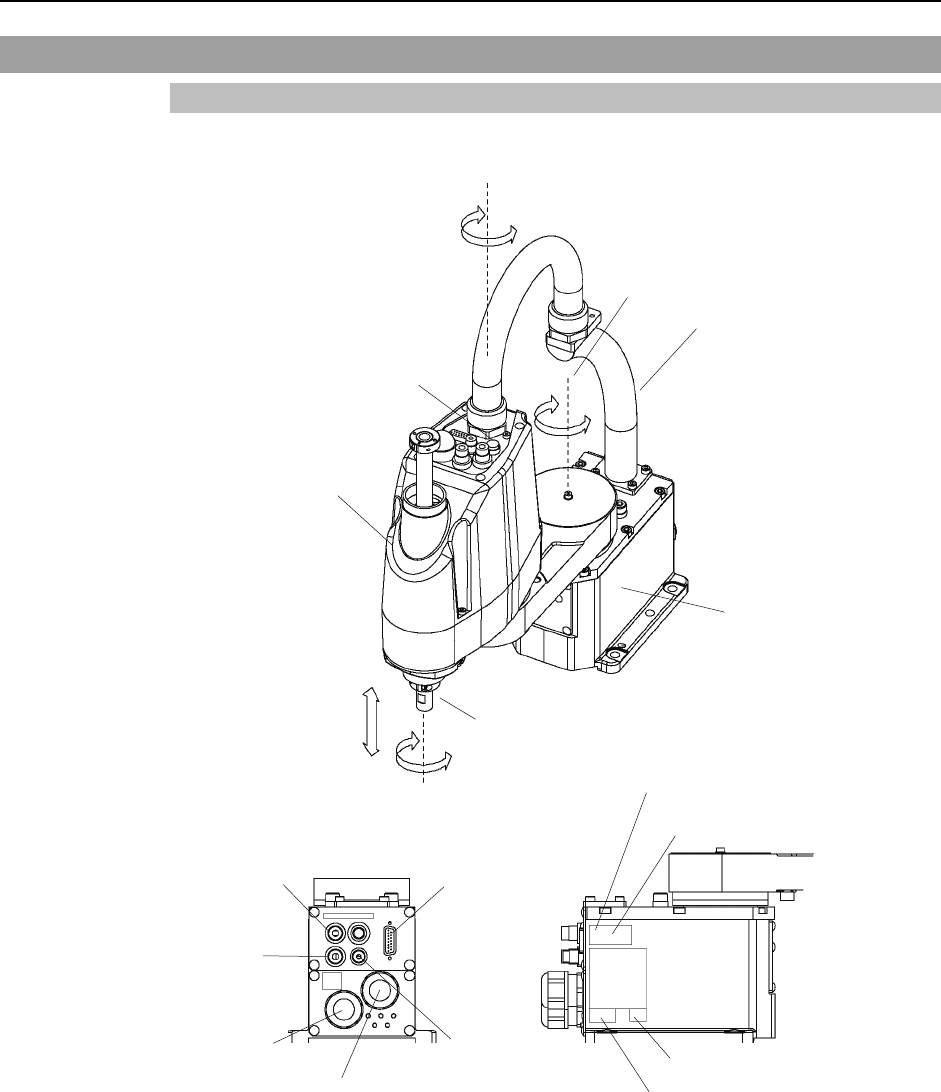
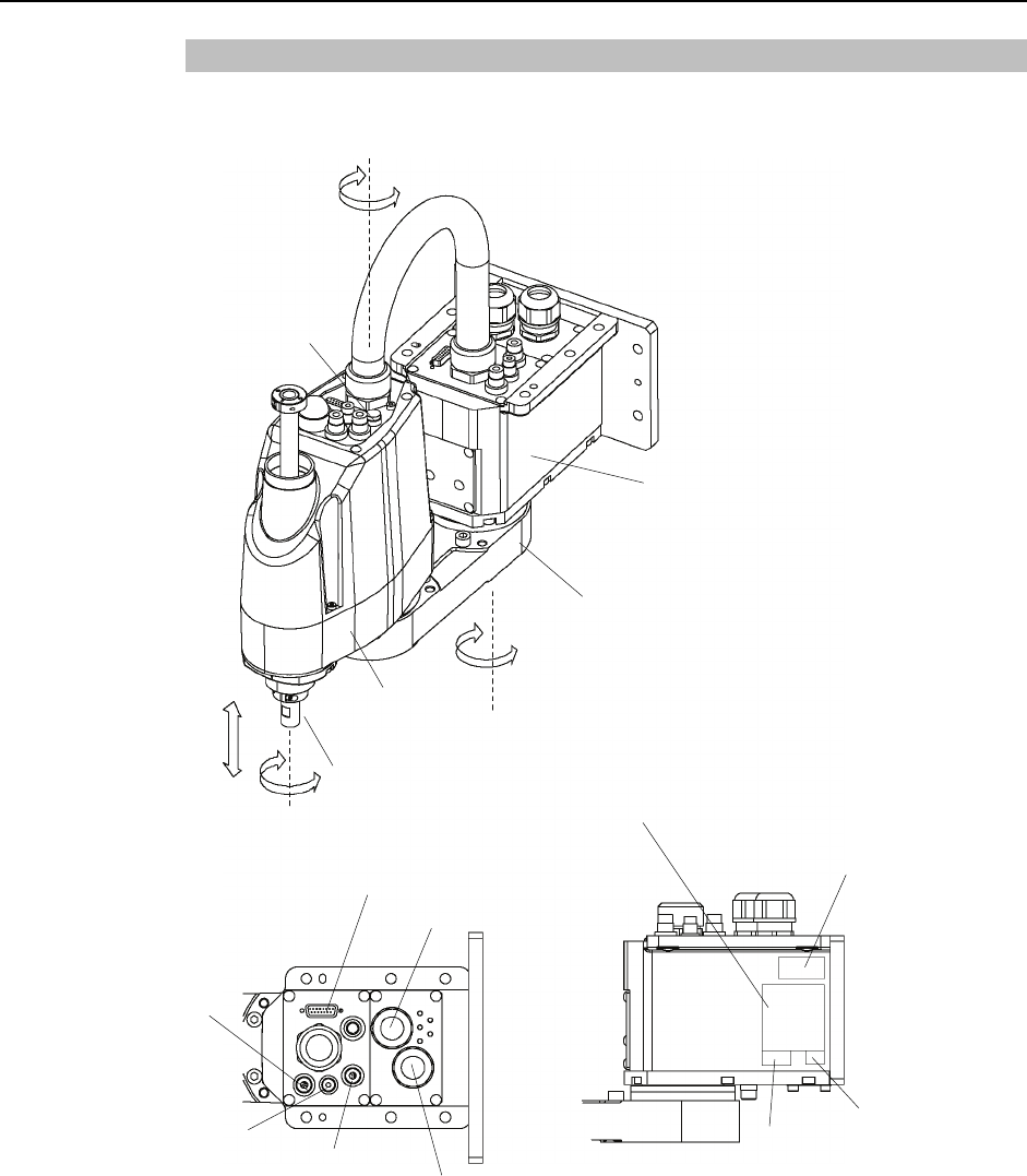
2.3.2 Multiple Mounting
Standard-model: G3-***1SM
+
−
+
−
+
−
+
−
CE label
UR label
Joint #3 / #4
Brake release switch
Joint #1
(rotating)
Joint #2
(rotating)
Joint #3
(Up/Down)
Arm #1
Arm #2
Base
Shaft
MT label (only for special order)
Face plate (Manipulator serial No.)
Signal cable
Power cable
Fitting (black)
for ø4 mm
pneumatic tube Fitting (black)
for ø6 mm
pneumatic tube
Fitting (white)
for ø6 mm
pneumatic tube
User connector
(15-pin D-sub connector)
The brake release button affects only Joints #3. When the brake release button is pressed in
emergency mode, the brake for Joint #3 is released simultaneously.
)
NOTE
Setup & Operation 2. Specifications
G3 Rev.1 17
G3-301SM G3-351SM
a 70 220
b Max.410 Max.450
shaft diameter
Max.ø11 through hole
mechanical stop diameter
Conical hole
Ø3,90°
1 mm flat cut
Detail of “A”
(
Calibration point position of Joints #3 and #4
)
(*) indicates the stroke margin by mechanical stop.
Reference through hole
(
View from the bottom of the base
)
or more Space for cables
Setup & Operation 2. Specifications
18 G3 Rev.1
Cleanroom-model: G3-***1CM
The following figures show the additional parts and specifications for Cleanroom-model (Multiple Mounting)
when compared with the Standard-model in appearance.
Upper bellows
Plate cover
(For Anti-static)
Exhaust port
Lower bellows
Setup & Operation 2. Specifications
G3 Rev.1 19
G3-301CM G3-351CM
a 70 220
b Max.410 Max.450
shaft diameter
Max.ø11 through hole
mechanical stop diameter
Conical hole
Ø3,90°
1 mm flat cut
Detail of “A”
(
Calibration
p
oint
p
osition of Joints #3 and #4
)
(*) indicates the stroke
margin by mechanical stop.
Reference through hole
(
View from the bottom of the base
)
or more Space for cables

Setup & Operation 2. Specifications
20 G3 Rev.1
2.4 Specifications
Item G3 series Manipulator
Arm #1, #2 250 mm 300 mm 350 mm
Arm #1 120 mm 170 mm 220 mm
Arm length
Arm #2 130 mm 130 mm 130 mm
Joints #1, #2 3550 mm/s 3950 mm/s 4350 mm/s
Joint #3 1100 mm/s
Max. operating
speed *1
Joint #4 3000 deg/s
Joints #1, #2 ± 0.008 mm ± 0.01 mm ± 0.01 mm
Joint #3 ± 0.001 mm Repeatability
Joint #4 ± 0.005 deg
Rated 1 kg
Payload (Load) Max. 3 kg
Rated 0.005 kg·m2
Joint #4 allowable
moment of inertia
*2
Max. 0.05 kg·m2
Joint #1 ± 140
Straight Joint #2 ± 141 ± 142
Right hand - − 115 to 150 − 105 to 160
Joint #1 Left hand - − 150 to 115 − 160 to 105
Right hand - − 135 to 150 − 120 to 165
Curved
Joint #2 Left hand - − 150 to 135 − 165 to 120
Joint #3 150
Max.
motion
range
Common Joint #4 ± 360
Joint #1 − 9786710 to 51729750
Straight Joint #2 ± 20534614 ± 20680249
Right hand - − 5825423 to 55924054 − 3495254 to 58254223
Joint #1 Left hand - − 13981014 to 47768463 − 16311183 to 45438294
Right hand - − 19660800 to 21845334 − 17476267 to 24029867
Curved
Joint #2 Left hand - − 21845334 to 19660800 − 24029867 to 17476267
Joint #3 −13653338 to 0
Max.
pulse
range
Common Joint #4 ± 23907534
Joints #1 0.00000377134 deg/pulse
Joint #2 0.00000686645 deg/pulse
Joint #3 0.00001098632 mm/pulse
Resolution
Joint #4 0.0001560107deg/pulse
Shaft diameter ø 16 mm
Hand Through hole ø 11mm
Mounting hole 120 × 120 mm (4-M8)
Weight (cables not included) 14 kg : 31 lb.
Driving method All joints AC servo motor
Joint #1 200 W
Joint #2 150 W
Joint #3 150 W
Motor
energy
consumption Joint #4 150 W
Installation method - Multiple Mounting
Option Installation environment Cleanroom *3 & ESD
Joint #3 down force 150 N
Installed wire for customer use 15 (15 pin: D-sub) 15 cores
2 pneumatic tubes (ø6 mm) : 0.59 Mpa (6 kgf/cm2 : 86 psi)
Installed pneumatic
ube for customer use t 1 pneumatic tubes (ø4 mm) : 0.59 Mpa (6 kgf/cm2 : 86 psi)

Setup & Operation 2. Specifications
G3 Rev.1 21
Item G3 series Manipulator
Ambient
Temperature 5 to 40°C (with minimum temperature variation)
Environmental
requirements Ambient relative
humidity 10 to 80% (no condensation)
Noise level *4 LAeq = 70 dB (A)
Applicable Controller RC180
SPEED 1 to (5) to100
ACCEL *5 1 to (10) to 120
SPEEDS 1 to (50) to 2000
ACCELS 1 to (200) to 25000
FINE 0 to (10000) to 65000
Assignable Value
( ) Default values
WEIGHT 0,130 to (1,130) 3,130
MTBF 3 years
Safety standard ANSI/RIA R15.06 compliant
CE compliant
*1: In the case of PTP command.
Maximum operating speed for CP command is 2000 mm/s on horizontal plane.
*2: In the case where the center of gravity is at the center of Joint #4.
If the center of gravity is not at the center of Joint #4, set the parameter using Inertia command.
*3: The exhaust system in the Cleanroom-model Manipulator draws air from the base interior and arm cover
interior together.
A crack or other opening in the base unit can cause loss of negative air pressure in the outer part of the
arm, which can cause increased dust emission.
Do not remove the maintenance cover on the front of the base.
Seal the exhaust port and the exhaust tube with vinyl tape so that the joint is airtight.
If the exhaust flow is not sufficient, dust particle emission may exceed the specified maximum level.
Cleanliness level : Class ISO 3 (ISO14644-1)
In previous criteria; Clean Class: 10 or its equivalent
Amount of Dust (0.1 µm diameter or larger) in 28317 cm3 (1cft)
sample-air around the center of the motion rang: 10 particles or less.
Exhaust System : Exhaust port diameter : Inner diameter: ø12 mm / Outer diameter: ø16 mm
Exhaust tube : Polyurethane tube
Outer diameter: ø12 mm (Inner diameter:ø8 mm) or
Inner diameter ø16mm or larger
Recommended exhaust flow rate : approx. 1000 cm3/s (Normal)
*4: Conditions of Manipulator during measurement as follows:
Operating conditions : Under rated load, 4-joints simultaneous motion, maximum speed, maximum
acceleration, and duty 50%.
Measurement point : In front of the Manipulator, 1000 mm apart from the motion range, 50 mm above
the base-installed surface.
*5: In general use, Accel setting 100 is the optimum setting that maintains the balance of acceleration and
vibration when positioning.
However, you may require an operation with high acceleration to shorten the cycle time by decreasing the
vibration at positioning. In this case, set Accel to larger than 100.
If you specify a larger Accel value, the frequency of the overload error and over heat may rise during
continuous operation. The use of large Accel setting is recommended only for necessary motions.

Setup & Operation 2. Specifications
22 G3 Rev.1
2.5 How to Set the Model
The Manipulator model for your system has been set before shipment from the factory. It
is normally not required to change the model when you receive your system.
CAUTION
■ When you need to change the setting of the Manipulator model, be sure to set the
Manipulator model properly. Improper setting of the Manipulator model may
result in abnormal or no operation of the Manipulator and/or cause safety
problems.
)
NOTE If an MT label is attached to the rear of a Manipulator, the Manipulator has custom
specifications. The custom specifications may require a different configuration
procedure; check the custom specifications number described on the MT label and contact
us when necessary.
The Manipulator model can be set from software.
Refer to the chapter Robot Configuration in the EPSON RC+ User’s Guide.

Setup & Operation 3. Environments and Installation
G3 Rev.1 23
3. Environments and Installation
3.1 Environmental Conditions
A suitable environment is necessary for the robot system to function properly and safely.
Be sure to install the robot system in an environment that meets the following conditions:
Item Conditions
Ambient temperature * 5 to 40°C (with minimum temperature variation)
Ambient relative humidity 10 to 80% (no condensation)
First transient burst noise 2 kV or less
Electrostatic noise 6 kV or less
Environment · Install indoors.
· Keep away from direct sunlight.
· Keep away from dust, oily smoke, salinity, metal
powder or other contaminants.
· Keep away from flammable or corrosive solvents
and gases.
· Keep away from water.
· Keep away from shocks or vibrations.
· Keep away from sources of electric noise.
Manipulators are not suitable for operation in harsh environments such as painting areas,
etc. When using Manipulators in inadequate environments that do not meet the above
conditions, please contact us.
)
NOTE
* The ambient temperature conditions are for the Manipulators only. For the Controller
the Manipulators are connected to, refer to the Controller manual.
Special Environmental Conditions
The surface of the Manipulator has general oil resistance. However, if your
requirements specify that the Manipulator must withstand certain kinds of oil, please
consult your distributor.
Rapid change in temperature and humidity can cause condensation inside the
Manipulator.
If your requirements specify that the Manipulator handles food, please consult your
distributor to check whether the Manipulator gives damage to the food or not.
The Manipulator cannot be used in corrosive environments where acid or alkaline is
used. In a salty environment where the rust is likely to gather, the Manipulator is
susceptible to rust.
WARNING
■ Use an earth leakage breaker on the AC power cable of the Controller to avoid
the electric shock and circuit breakdown caused by an unexpected water leak.
Prepare the earth leakage brake that pertains the controller you are using. For
details, refer to the controller manual.
Setup & Operation 3. Environments and Installation
24 G3 Rev.1
3.2 Base Table
A base table for anchoring the Manipulator is not supplied. Please make or obtain the
base table for your Manipulator. The shape and size of the base table differs depending
on the use of the robot system. For your reference, we list some Manipulator table
requirements here.
The torque and reaction force produced by the movement of the Manipulator are as
follows:
Max. Reaction torque on the horizontal plate : 500 Nm
Max. Horizontal reaction force : 2500 N
Max. Vertical reaction force : 1500 N
The threaded holes required for mounting the Manipulator base are M8. Use mounting
bolts with specifications conforming to ISO898-1 property class: 10.9 or 12.9.
For dimensions, refer to Setup & Operation: 3.3 Mounting Dimensions.
The plate for the Manipulator mounting face should be 20 mm thick or more and made of
steel to reduce vibration. The surface roughness of the steel plate should be 25 μm or
less.
The table must be secured on the floor or wall to prevent it from moving.
The Manipulator must be installed horizontally.
When using a leveler to adjust the height of the base table, use a screw with M16 diameter
or more.
If you are passing cables through the holes on the base table, see the figures below.
[unit : mm]
Power Cable
Connector
Signal Cable
Connector
47
26
53
18
M/C Cables
Do not remove the M/C cables from the Manipulator.
For environmental conditions regarding space when placing the Controller on the base
table, refer to the Controller manual.
)
NOTE
WARNING
■ To ensure safety, a safeguard must be installed for the robot system.
For details on the safeguard, refer to the EPSON RC+ User’s Guide.

Setup & Operation 3. Environments and Installation
G3 Rev.1 25
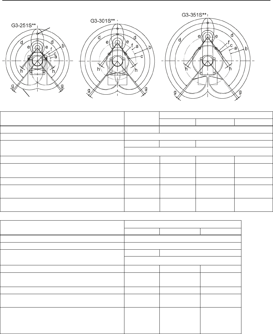
3.3 Mounting Dimensions
The maximum space described in figures shows that the radius of the end effector is 60
mm or less. If the radius of the end effector exceeds 60 mm, define the radius as the
distance to the outer edge of maximum space.
If a camera or electromagnetic valve extends outside of the arm, set the maximum range
including the space that they may reach.
Be sure to allow for the following extra spaces in addition to the space required for
mounting the Manipulator, Controller, and peripheral equipment.
space for teaching
space for maintenance and inspection
(Ensure a space to open the rear side cover and the maintenance cover for
maintenance.)
space for cables
The minimum bend radius of the power cable is 90 mm. When installing the cable, be
sure to maintain sufficient distance from obstacles. In addition, leave enough space for
other cables so that they are not bent forcibly.
Ensure distance to the safeguard from the maximum motion range is more than 100 mm.
Setup & Operation 3. Environments and Installation
26 G3 Rev.1
A A
B
A B
B
B
A
T
able Top Mounting
Center of Joint #3
Maximum space
G3-301S/C
G3-251S/C Standard -R -L
a Length of Arm #1 (mm) 120 170
b Length of Arm #2 (mm) 130
84 / 92 104.8 / 107.1 120.7
c (Motion range) Z : 150/120
d Motion range of Joint #1 (degree) 140 140
−125 to +150 −150 to +125
e Motion range of Joint #2 (degree) 141 / 137 142 / 141 −135 to +150
/ −135 to +145
−150 to +135
/ −145 to +135
f (Mechanical stop area) 79.3 104.8 / 107.1 96.2 86.8
g Joint #1 angle to hit mechanical stop (degree) 2 2
A:3
B:6
A:6
B:3
h Joint #2 angle to hit mechanical stop (degree) 2.3 3.8
A:8.3
B:3.3
A:3.3
B:8.3
G3-351S/C
Standard -R -L
a Length of Arm #1 (mm) 220
b Length of Arm #2 (mm) 130
142.3 / 146.6 191.6
c (Motion range) Z : 150/120
d Motion range of Joint #1 (degree) 140 −110 to +165 −165 to +110
e Motion range of Joint #2 (degree) −142 −120 to +165
/ −120 to+160 −165 to +120
f (Mechanical stop area) 134.2 100.3 / 107.5 100.3 / 107.5
g Joint #1 angle to hit mechanical stop (degree) 2 A:5
B:4
A:4
B:5
h Joint #2 angle to hit mechanical stop (degree) 3.8
A:2.8
B:3.8
/ A:7.8
B:3.8
A:3.8
B:2.8
/ A:3.8
B:7.8
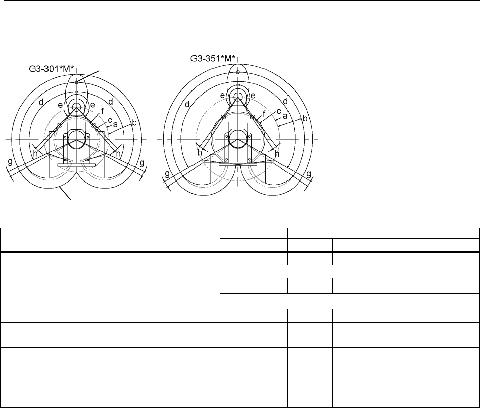
Setup & Operation 3. Environments and Installation
G3 Rev.1 27
A
B
B
A
Multiple Mounting
Center of Joint #3
Maximum space
G3-301SM/CM G3-351SM/CM
Standard Standard -R -L
a Length of Arm #1 (mm) 170 220 220 220
b Length of Arm #2 (mm) 130
120.7 142.3
125.6 / 140.5 125.6 / 140.5
c (Motion range)
Z : 150 / 120
d Motion range of Joint #1 (degree) 115 120
−105 to +130 −130 to +105
e Motion range of Joint #2 (degree) 135 142
−120 to +160
/ −120 to +150
−160 to +120
/ −150 to +120
f (Mechanical stop area) 112 134.2 103.3 / 125.6 103.3 / 125.6
g Joint #1 angle to hit mechanical stop (degree) 4 4
A:3.3
B:5
A:5
B:3.3
h Joint #2 angle to hit mechanical stop (degree) 3.8 3.8
A:3.8
B:2.8
A:2.8
B:3.8
Setup & Operation 3. Environments and Installation
3.4 Unpacking and Transportation
THE INSTALLATION SHALL BE PREFORMED BY QUALIFIED INSTALLATION
PERSONNEL AND SHOULD CONFORM TO ALL NATIONAL AND LOCAL
CODES.
WARNING
■ Only authorized personnel should perform sling work and operate a crane and a
forklift. When these operations are performed by unauthorized personnel, it is
extremely hazardous and may result in serious bodily injury and/or severe
equipment damage to the robot system.
■ Using a cart or similar equipment, transport the Manipulator in the same manner
as it was delivered.
■ After removing the bolts securing the Manipulator to the delivery equipment, the
Manipulator can fall. Be careful not to get hands or fingers caught.
■ The arm is secured with a wire tie. Leave the wire tie secured until you finish the
installation so as not to get hands or fingers caught.
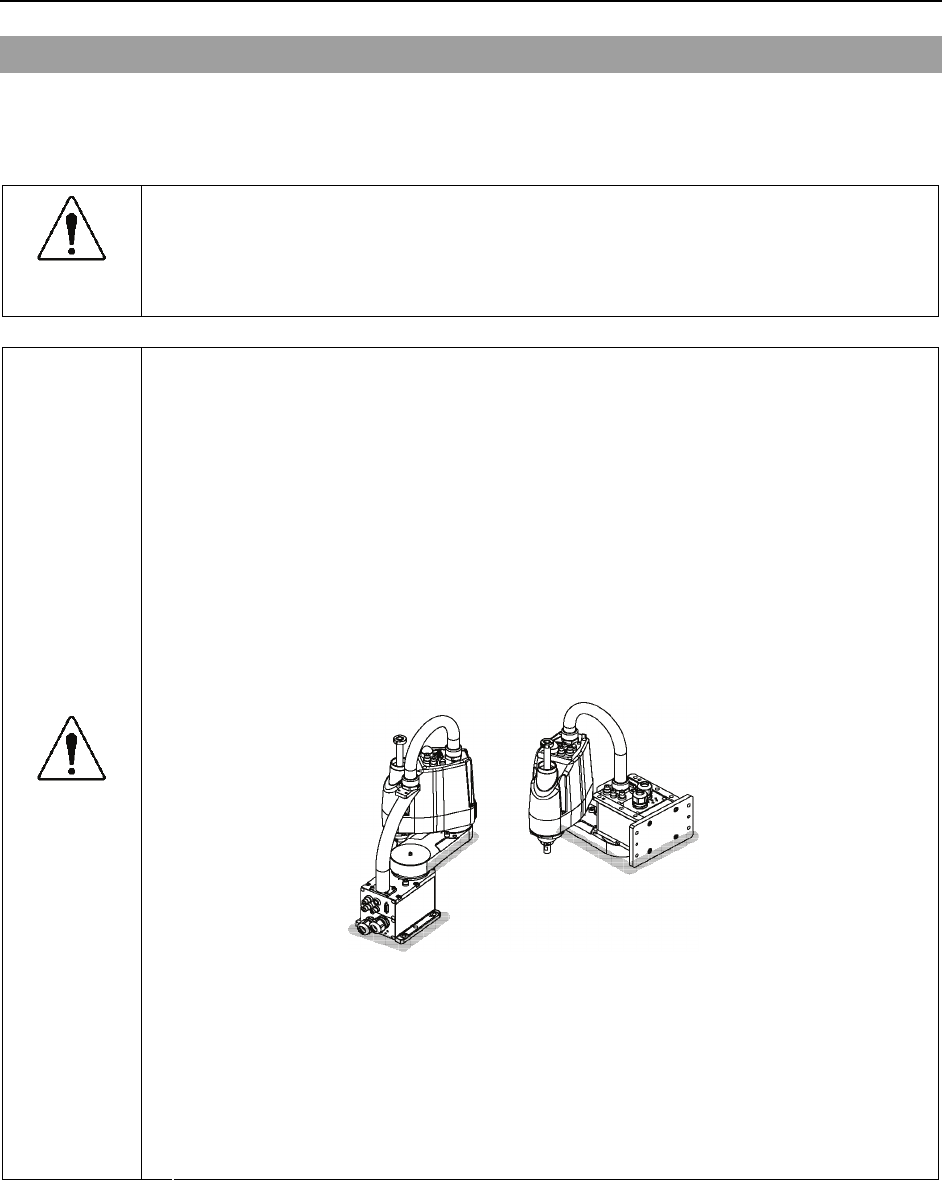
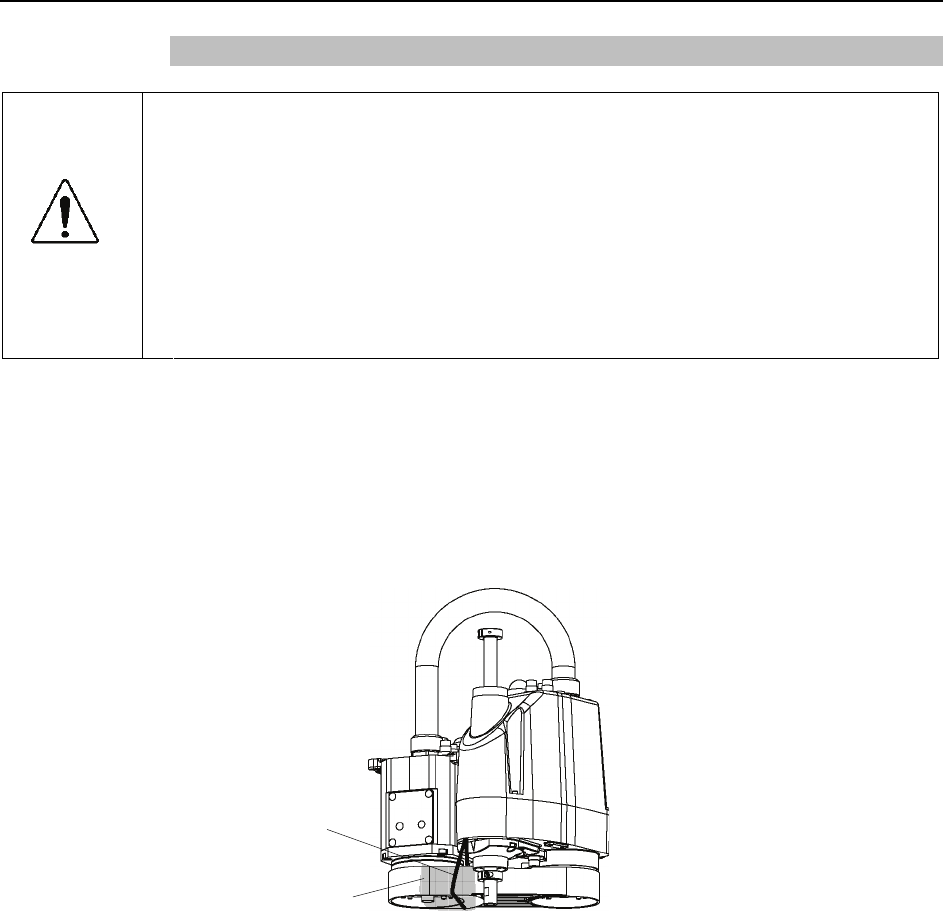
■ To carry the Manipulator, have two or more people to work on it and secure the
Manipulator to the delivery equipment or hold the areas indicated in gray in the
figure (bottom of Arm #1 and bottom of the base) by hand.
When holding the bottom of the base by hand, be very careful not to get your
hands or fingers caught.
Table Top Mounting
G3-251S : approx. 27 kg: 60 lb.
Multiple Mounting
G3-301*M : approx. 29 kg: 64 lb.
G3-351*M : approx. 29.5 kg: 65 lb
G3-301S : approx. 27 kg: 60 lb.
G3-351S : approx. 28 kg: 62 lb.
■ Stabilize the Manipulator with your hands when hoisting it.
CAUTION
■ When transporting the Manipulator for a long distance, secure it to the delivery
equipment directly so that the Manipulator never falls.
If necessary, pack the Manipulator in the same style as it was delivered.
28 G3 Rev.1
Setup & Operation 3. Environments and Installation
G3 Rev.1 29
3.5 Installation Procedure
The following sections describe the installation of the Standard Manipulator.
3.5.1 Table Top Mounting
3.5.2 Multiple Mounting
For Cleanroom-model manipulator, refer to this section;
3.5.3 Cleanroom-model
3.5.1 Table Top Mounting
CAUTION
■ Install the Table Top Mounting Manipulator with two or more people.
The Manipulator weights are as follows. Be careful not to get hands, fingers, or
feet caught and/or have equipment damaged by a fall of the Manipulator.
G3-251S : approx. 27 kg: 60 lb.
G3-301S : approx. 27 kg: 60 lb.
G3-351S : approx. 28 kg: 62 lb.
Standard-model
20 mm
4-M8
×
40
Screw Hole
Spring
Washer
Plane
Washer
(depth 20 mm
or more)
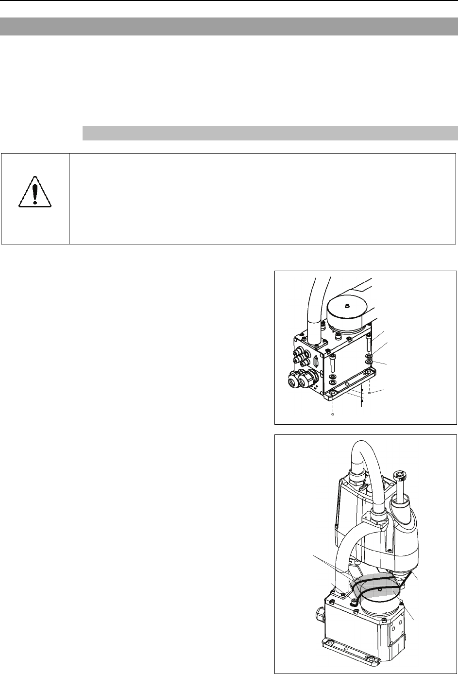
(1) Secure the base to the base table with
four bolts.
Use bolts with specifications conforming
to ISO898-1 Property Class: 10.9 or
12.9.
(2) Using nippers, cut off the wire tie
binding the shaft and arm retaining
bracket on the base.
(3) Remove the bolts securing the wire ties
removed in step (2).
)
NOTE
Bolt
:M4×15
Bolt
:M8×20
Wire tie
Sheet
Setup & Operation 3. Environments and Installation
30 G3 Rev.1
3.5.2 Multiple Mounting
■ Install the Multiple Mounting Manipulator with two or more people.
The Manipulator weights are as follows. Be careful not to get hands, fingers, or
feet caught and/or have equipment damaged by a fall of the Manipulator.
G3-301*M : approx. 29 kg: 64 lb.
G3-351*M : approx. 29.5 kg: 65 lb.
WARNING ■ When installing the Manipulator to the wall, support the Manipulator, and then
secure the anchor bolts. Removing the support without securing the anchor
bolts properly is extremely hazardous and may result in fall of the Manipulator.
Standard-model
(1)
Unpack the manipulator with retaining the
arm posture.
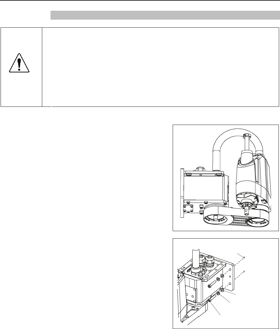
(2) Secure the base to the wall with four bolts.
Use bolts with specifications conforming
to ISO898-1 Property Class: 10.9 or 12.9.
4-M8 40 ×
Screw Hole
(depth 20 mm or more)
Spring Washe
r
Plane Washe
r
)
NOTE
Setup & Operation 3. Environments and Installation
3.5.3 Cleanroom-model
(1) Unpack it outside of the clean room.
(2) Secure the Manipulator to delivery equipment such as a pallet with bolts so that the
Manipulator does not fall.
(3) Wipe off the dust on the Manipulator with a little alcohol or distilled water on a
lint-free cloth.
(4) Carry the Manipulator in the clean room.
(5) Refer to the installation procedure of each Manipulator model and install the
Manipulator.
(6) Connect an exhaust tube to the exhaust port.
CAUTION
■ When operating the Manipulator under special environmental conditions (adverse
conditions with dust and oily smoke), do not place the controller in the same
condition since the controller does not comply with IP54 / IP65. Doing so may
cause equipment damage to and/or malfunction of the controller.
3.6 Connecting the Cables
■ To shut off power to the robot system, pull out the power plug from the power
source. Be sure to connect the AC power cable to a power receptacle. DO
NOT connect it directly to a factory power source.
■ Before performing any replacement procedure, turn OFF the Controller and related
equipment, and then pull out the power plug from the power source.
Performing any replacement procedure with the power ON is extremely hazardous
and may result in electric shock and/or malfunction of the robot system.
WARNING ■ Be sure to connect the cables properly. Do not allow unnecessary strain on the
cables. (Do not put heavy objects on the cables. Do not bend or pull the cables
forcibly.) The unnecessary strain on the cables may result in damage to the
cables, disconnection, and/or contact failure. Damaged cables, disconnection,
or contact failure is extremely hazardous and may result in electric shock and/or
improper function of the robot system.
CAUTION
■ When connecting the Manipulator to the Controller, make sure that the serial
numbers on each equipment match. Improper connection between the
Manipulator and Controller may not only cause improper function of the robot
system but also serious safety problems. The connection method varies with the
Controller used. For details on the connection, refer to the Controller manual.
If the G series Manipulator or E2 series Manipulator is connected to the Controller
for the PS series (ProSix), it may result in malfunction of the Manipulator.
G3 Rev.1 31
Setup & Operation 3. Environments and Installation
32 G3 Rev.1
When the Manipulator is a Cleanroom-model, be aware of the followings.
For the Manipulator of Cleanroom-model, use it with an exhaust system.
For details, refer to Setup & Operation: 2.4 Specifications.
CAUTION
■ When operating the Manipulator under special environmental conditions (adverse
conditions with dust and oily smoke), do not place the controller in the same
condition since the controller does not comply with IP54 / IP65. Doing so may
cause equipment damage to and/or malfunction of the controller.
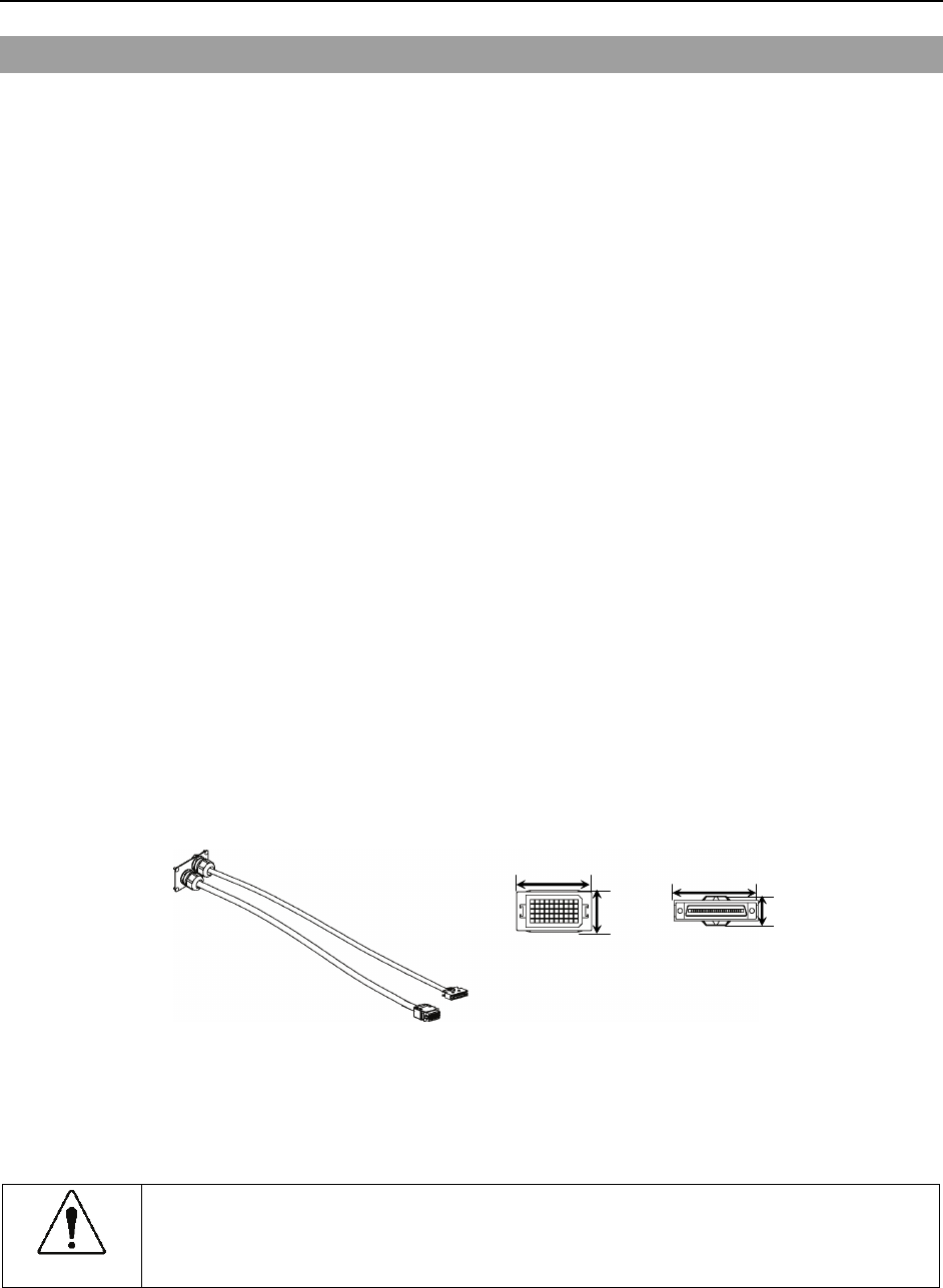
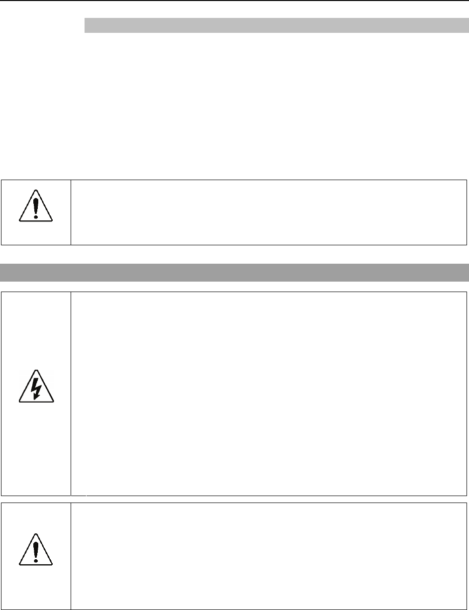
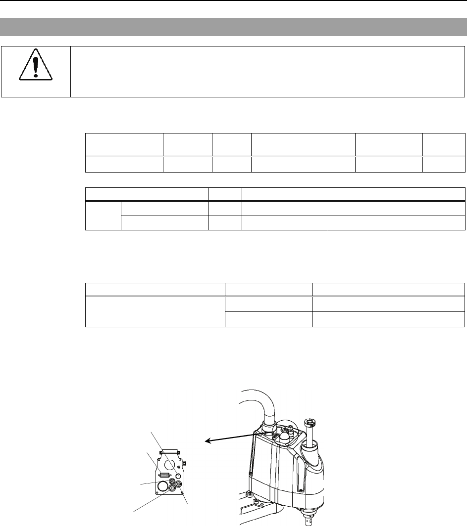
Cable Connections
Connect the power connector and signal connector of the M/C cables to the Controller.
Power Connector
Signal Connector
Setup & Operation 3. Environments and Installation
3.7 User Wires and Pneumatic Tubes
CAUTION
■ Only authorized or certified personnel should be allowed to perform wiring.
Wiring by unauthorized or uncertified personnel may result in bodily injury and/or
malfunction of the robot system.
User electrical wires and pneumatic tubes are contained in the cable unit.
Electrical Wires
Rated Voltage Allowable
Current Wires Nominal Sectional Area Outer Diameter Note
AC/DC30 V 1 A 15 0.211 mm2 ø8.3±0.3 mm Shielded
Maker Standard
Suitable Connector JAE DA-15PF-N (Solder type)
15 pin Clamp Hood JAE DA-C8-J10-F2-1R (Connector setscrew: #4-40 NC)
Pins with the same number, indicated on the connectors on both ends of the cables, are
connected.
Pneumatic Tubes
Max. Usable Pneumatic Pressure Pneumatic Tubes Outer Diameter × Inner Diameter
2 ø6 mm × ø4 mm
0.59 MPa (6 kgf/cm2 : 86 psi) 1 ø4 mm × ø2.5 mm
Fittings for ø6 mm and ø4 mm (outer diameter) pneumatic tubes are supplied on both ends
of the pneumatic tubes.
Common Parts
Fitting (white) for
ø6 mm pneumatic tube
Fitting (black) for
ø6 mm pneumatic tube
Brake release
button switch
15-pin D-sub connector
Fitting (black) for
ø4 mm pneumatic tube
G3 Rev.1 33
Setup & Operation 3. Environments and Installation
34 G3 Rev.1
Table Top Mounting
Fitting (black)
for ø4 mm pneumatic tube
Fitting (black) for
ø6 mm pneumatic tube
Fitting (white) for
ø6 mm pneumatic tube User connector
(15-pin D-sub connector)
Multiple Mounting
Fitting (black) for
ø6 mm pneumatic tube
User connector
(15-pin D-sub connector)
Fitting (white) for
ø6 mm pneumatic tube
Fitting (black) for
ø4 mm pneumatic tube
Setup & Operation 3. Environments and Installation
3.8 Relocation and Storage
3.8.1 Precautions for Relocation and Storage
Observe the following when relocating, storing, and transporting the Manipulators.
THE INSTALLATION SHALL BE PREFORMED BY QUALIFIED INSTALLATION
PERSONNEL AND SHOULD CONFORM TO ALL NATIONAL AND LOCAL
CODES.
WARNING
■ Only authorized personnel should perform sling work and operate a crane and a
forklift. When these operations are performed by unauthorized personnel, it is
extremely hazardous and may result in serious bodily injury and/or severe
equipment damage to the robot system.
■ Before relocating the Manipulator, fold the arm and secure it tightly with a wire tie
to prevent hands or fingers from being caught in the Manipulator.
■ When removing the anchor bolts, support the Manipulator to prevent falling.
Removing the anchor bolts without support may result in a fall of the Manipulator,
and then get hands, fingers, or feet caught.
■ To carry the Manipulator, have two or more people to work on it and secure the
Manipulator to the delivery equipment or hold the bottom of Arm #1, the bottom of
the main cable fitting, and the bottom of the base by hand. When holding the
bottom of the base by hand, be very careful not to get hands or fingers caught.
CAUTION
■ Stabilize the Manipulator with your hands when hoisting it. Unstable hoisting is
extremely hazardous and may result in fall of the Manipulator.
When transporting the Manipulator for a long distance, secure it to the delivery
equipment so that the Manipulator cannot fall.
If necessary, pack the Manipulator in the same way as it was delivered.
When the Manipulator is used for a robot system again after long-term storage,
perform a test run to verify that it works properly, and then operate it thoroughly.
Transport and store the Manipulator in the range of -25°C to +55°C.
Humidity within 10% to 90% is recommended.
When condensation occurs on the Manipulator during transport or storage, turn
ON the power only after the condensation dries.
Do not shock or shake the Manipulator during transport.
G3 Rev.1 35
Setup & Operation 3. Environments and Installation
36 G3 Rev.1
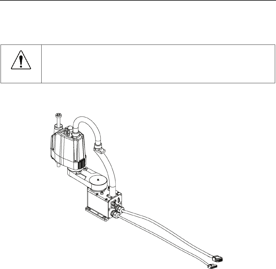
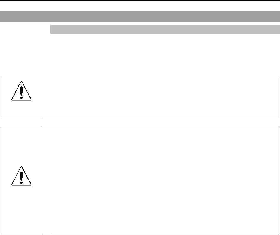
3.8.2 Table Top Mounting
CAUTION
■ Install or relocate the Table Top Mounting Manipulator with two or more people.
The Manipulator weights are as follows. Be careful not to get hands, fingers, or
feet caught and/or have equipment damaged by a fall of the Manipulator.
G3-251S : approx. 27 kg: 60 lb.
G3-301S : approx. 27 kg: 60 lb.
G3-351S : approx. 28 kg: 62 lb.
(1) Turn OFF the power on all devices and unplug the cables.
Remove the mechanical stops if using them to limit the motion range of Joints #1 and
#2. For details on the motion range, refer to Setup & Operation: 5.2 Motion Range
Setting by Mechanical Stops.
)
NOTE
(2) Cover the arm with a sheet so that the arm will not be damaged.
Tie the lower end of the shaft and arm, and the base and arm together with a wire tie.
Be careful not to tie them too tight. Otherwise, the shaft may bend.
Bolt
:M4×15
Bolt
:M8×20
Wire tie
Sheet
Example of Arm Retaining Posture
(3) Hold the bottom of Arm #1 by hand to unscrew the anchor bolts.
Then, remove the Manipulator from the base table.
Setup & Operation 3. Environments and Installation
G3 Rev.1 37
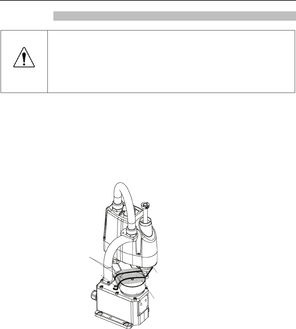
3.8.3 Multiple Mounting
■ Install or relocate the Multiple Mounting Manipulator with two or more people.
The Manipulator weights are as follows. Be careful not to get hands, fingers, or
feet caught and/or have equipment damaged by a fall of the Manipulator.
G3-301*M : approx. 29 kg: 64 lb.
G3-351*M : approx. 29.5 kg: 65 lb.
WARNING ■ When removing the Manipulator from the wall, support the Manipulator, and then
remove the anchor bolts. Removing the anchor bolts without supporting is
extremely hazardous and may result in fall of the Manipulator.
(1) Turn OFF the power on all devices and unplug the cables.
Remove the mechanical stops if using them to limit the motion range of Joints #1 and
#2. For details on the motion range, refer to Setup & Operation: 5.2 Motion Range
Setting by Mechanical Stops.
)
NOTE
(2) Cover the arm with a sheet so that the arm will not be damaged.
Refer to the figure below and bind the shaft and arm retaining bracket on the base.
Sheet
Wire tie
Example of Arm
Retaining Posture
(3) Hold the bottom of Arm #1 by hand to unscrew the anchor bolts. Then, remove the
Manipulator from the wall.
Setup & Operation 4. Setting of End Effectors
4. Setting of End Effectors
4.1 Attaching an End Effector
Users are responsible for making their own end effector(s). Before attaching an end
effector, observe these guidelines.
CAUTION
■ If you use an end effector equipped with a gripper or chuck, connect wires and/or
pneumatic tubes properly so that the gripper does not release the work piece
when the power to the robot system is turned OFF. Improper connection of the
wires and/or pneumatic tubes may damage the robot system and/or work piece
as the work piece is released when the Emergency Stop switch is pressed.
I/O outputs are configured at the factory so that they are automatically shut off (0)
by power disconnection, the Emergency Stop switch, or the safety features of the
robot system.
Shaft
- Attach an end effector to the lower end of the shaft.
For the shaft dimensions, and the overall dimensions of the Manipulator, refer to Setup
& Operation: 2. Specifications.
- Do not move the upper limit mechanical stop on the lower side of the shaft.
Otherwise, when “Jump motion” is performed, the upper limit mechanical stop may hit
the Manipulator, and the robot system may not function properly.
- Use a split muff coupling with an M4 bolt or larger to attach the end effector to the
shaft.
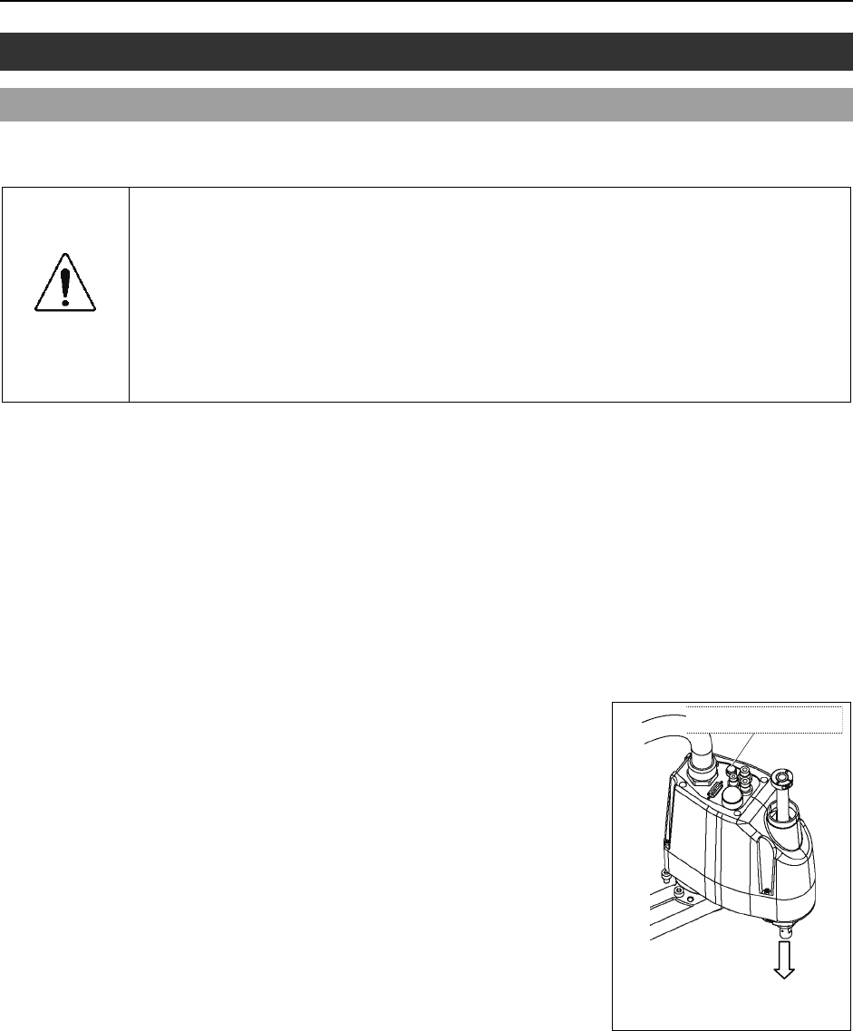
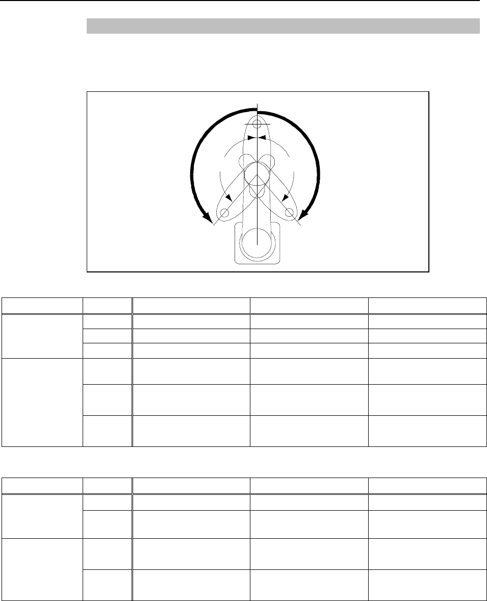
Brake release button
- Joint #3 cannot be moved up/down by hand because
the electromagnetic brake is applied to the joint while
power to the robot system is turned OFF.
This prevents the shaft from hitting peripheral
equipment in the case that the shaft is lowered by the
weight of the end effector when the power is
disconnected during operation, or when the motor is
turned OFF even though the power is turned ON.
To move Joint #3 up/down while attaching an end
effector, turn ON the Controller and press the brake
release button.
Brake release button
The shaft may be lowered by
the weight of the end effector.
This button switch is a momentary-type; the brake is released only while the button
switch is being pressed.
- Be careful of the shaft while the brake release button is being pressed because the shaf
t
may be lowered by the weight of the end effector.
Layouts
- When you operate the manipulator with an end effector, the end effector may interfere
with the Manipulator because of the outer diameter of the end effector, the size of the
work piece, or the position of the arms. When designing your system layout, pay
attention to the interference area of the end effector.
38 G3 Rev.1
Setup & Operation 4. Setting of End Effectors
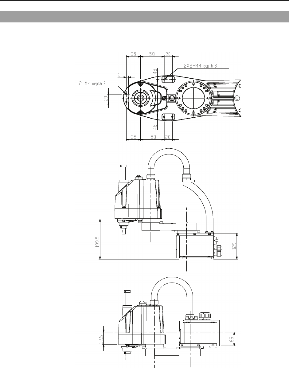
4.2 Attaching Cameras and Valves
Arm #2 has threaded holes as shown in the figure below. Use these holes for attaching
cameras, valves, and other equipment. [Unit: mm]
Common Dimensions
Multiple Mounting
Table Top Mounting
From the base mountin
g
face
m the reference hole
From the base mountin
Fro
g
face
G3 Rev.1 39
Setup & Operation 4. Setting of End Effectors
4.3 Weight and Inertia Settings
To ensure optimum Manipulator performance, it is important to make sure that the load
(weight of the end effector and work piece) and moment of inertia of the load are within
the maximum rating for the Manipulator, and that Joint #4 does not become eccentric.
If the load or moment of inertia exceeds the rating or if the load becomes eccentric, follow
the steps below, “4.3.1Weight Setting” and “4.3.2 Inertia Setting” to set parameters.
Setting parameters makes the PTP motion of the Manipulator optimal, reduces vibration to
shorten the operating time, and improves the capacity for larger loads. In addition, it
reduces persistent vibration produced when the moment of inertia of the end effector and
work piece is larger that the default setting.
4.3.1 Weight Setting
CAUTION
■ The total weight of the end effector and the work piece must not exceed 3 kg.
The G3 series Manipulators are not designed to work with loads exceeding 3 kg.
Always set the Weight parameters according to the load. Setting a value that is
smaller than the actual load may cause errors, excessive shock, insufficient
function of the Manipulator, and/or shorten the life cycle of parts/mechanisms.
The acceptable weight capacity (end effector and work piece) in G3 series is 1 kg at the
default rating and 3 kg at the maximum. When the load (weight of the end effector and
work piece) exceeds the rating, change the setting of Weight parameter.
After the setting is changed, the maximum acceleration/deceleration speed of the robot
system at PTP motion corresponding to the “Weight Parameter” is set automatically.
Load on the Shaft
The load (weight of the end effector and work piece) on the shaft can be set by Weight
parameter.
Enter a value into the [Load inertia:] text box on the [Inertia] panel ([Tools] - [Robo
t
Manager]). (You may also execute the Inertia command from the [Command Window].)
EPSON
RC+
Load on the Arm
When you attach a camera or other devices to the arm, calculate the weight as the
equivalent of the shaft. Then, add this to the load and enter the total weight to the Weight
parameter.
Equivalent Weight Formula
When you attach the equipment near Arm #2:
When you attach the equipment to the end of Arm #2:
WM = M (L1)2/(L1+L2)2
WM = M (LM)2/(L2)2
WM
M
L1
L2
LM
: equivalent weight
: weight of camera etc.
: length of Arm #1
: length of Arm #2
: distance from rotation center of Joint #2 to center of gravity
of camera etc.
40 G3 Rev.1
Setup & Operation 4. Setting of End Effectors
G3 Rev.1 41
<Example> A “1 kg” camera is attached to the end of the G3 series arm (180 mm
away from the rotation center of Joint #2) with a load weight of “1
kg”.
M = 1
L2 = 130
LM = 180
WM = 1 × 1802/1302 = 1.538 → 1.6 (round up)
W + WM = 1 + 1.6 = 2.6
Enter “2.6” for the Weight Parameter.
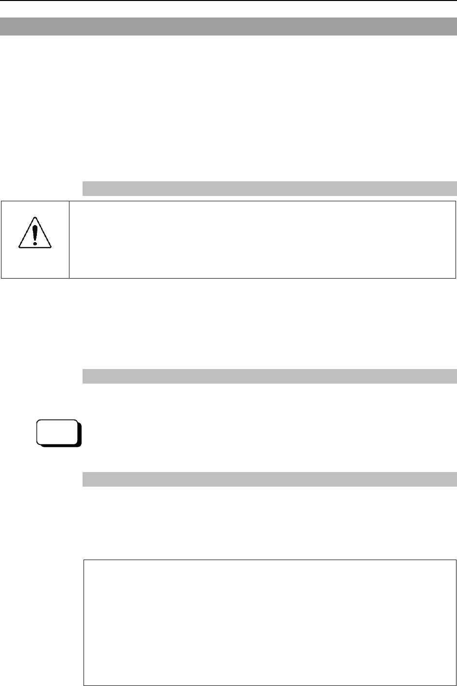
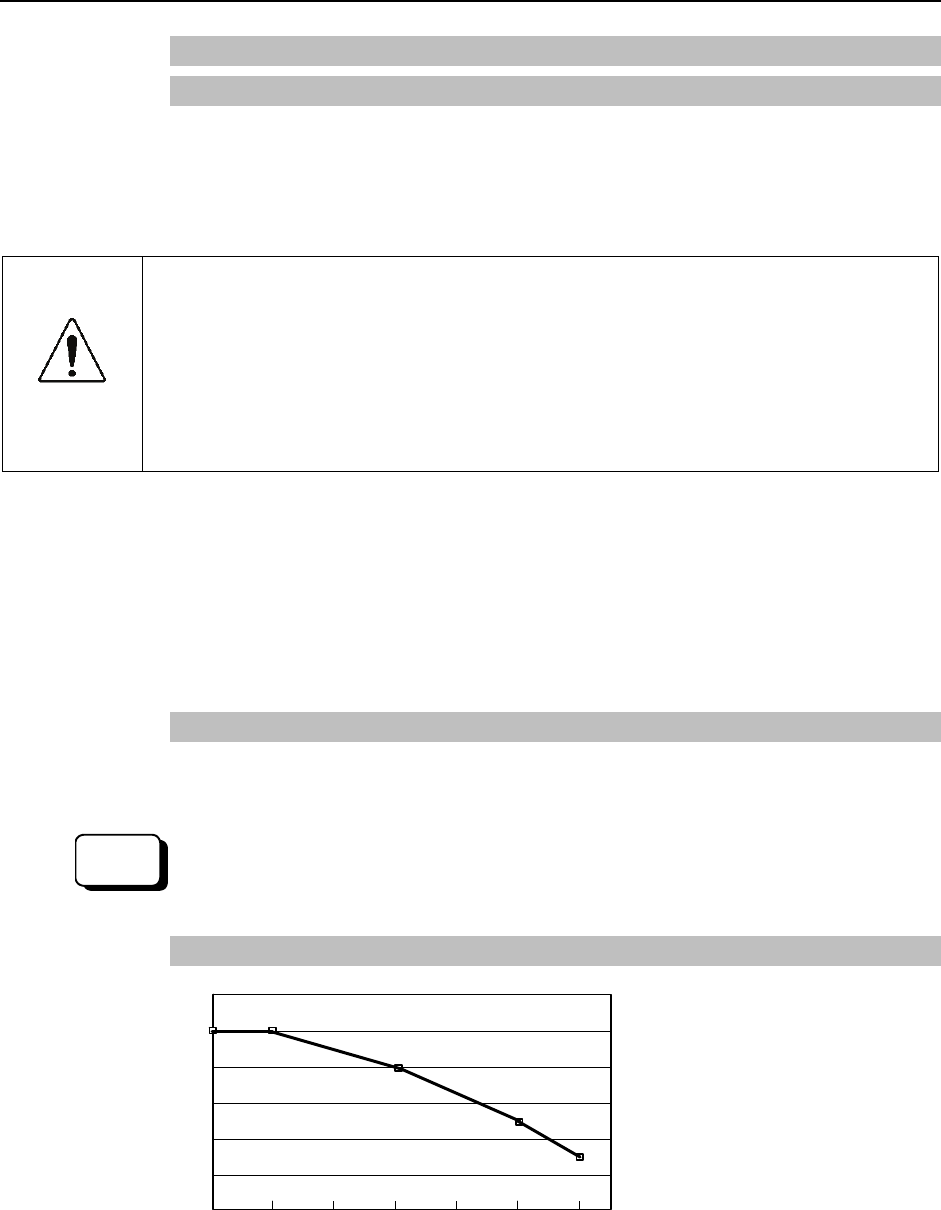
Automatic speed setting by Weight
140
120
100
80
60
40
20
0 1 1.5 2 2.5 3 (kg) Weight setting
(%) * The percentage in the graph
is based on the speed at
rated weight (1 kg) as 100%.
100
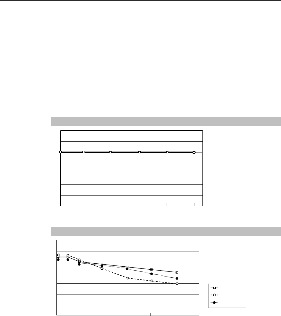
Automatic acceleration/deceleration setting by Weight
140
120
100
80
60
40
20
0 1 1.5 2 2.5 3 (kg) Weight setting
(%) * The percentage in the graph is
based on the acceleration
/ deceleration at rated weight
(3 kg) as 100%.
110
80
110
70
90
100
70
60 G3-25***
G3-30***
G3-35***
Setup & Operation 4. Setting of End Effectors
4.3.2 Inertia Setting
Moment of Inertia and the Inertia Setting
The moment of inertia is defined as “the ratio of the torque applied to a rigid body and its
resistance to motion”. This value is typically referred to as “the moment of inertia”,
“inertia”, or “GD2”. When the Manipulator operates with additional objects (such as an
end effector) attached to the shaft, the moment of inertia of load must be considered.
CAUTION
■ The moment of inertia of the load (weight of the end effector and work piece)
must be 0.05 kgwm2 or less. The G3 series Manipulators are not designed to
work with a moment of inertia exceeding 0.05 kgwm2.
Always set the moment of inertia parameter to the correct moment of inertia.
Setting a value that is smaller than the actual moment of inertia may cause
errors, excessive shock, insufficient function of the Manipulator, and/or shorten
the life cycle of parts/mechanisms.
The acceptable moment of inertia of load for a G3 series Manipulator is 0.005 kgwm2 at the
default rating and 0.05 kgwm2 at the maximum. When the moment of inertia of the load
exceeds the rating, change the setting of the moment of inertia parameter of the Inertia
command. After the setting is changed, the maximum acceleration/deceleration speed of
Joint #4 at PTP motion corresponding to the “moment of inertia” value is set
automatically.
Moment of inertia of load on the shaft
The moment of inertia of load (weight of the end effector and work piece) on the shaft can
be set by the “moment of inertia” parameter of the Inertia command.
EPSON
RC+
Enter a value into the [Load inertia:] text box on the [Inertia] panel ([Tools] - [Robo
t
Manager]). (You may also execute the Inertia command from the [Command Window].)
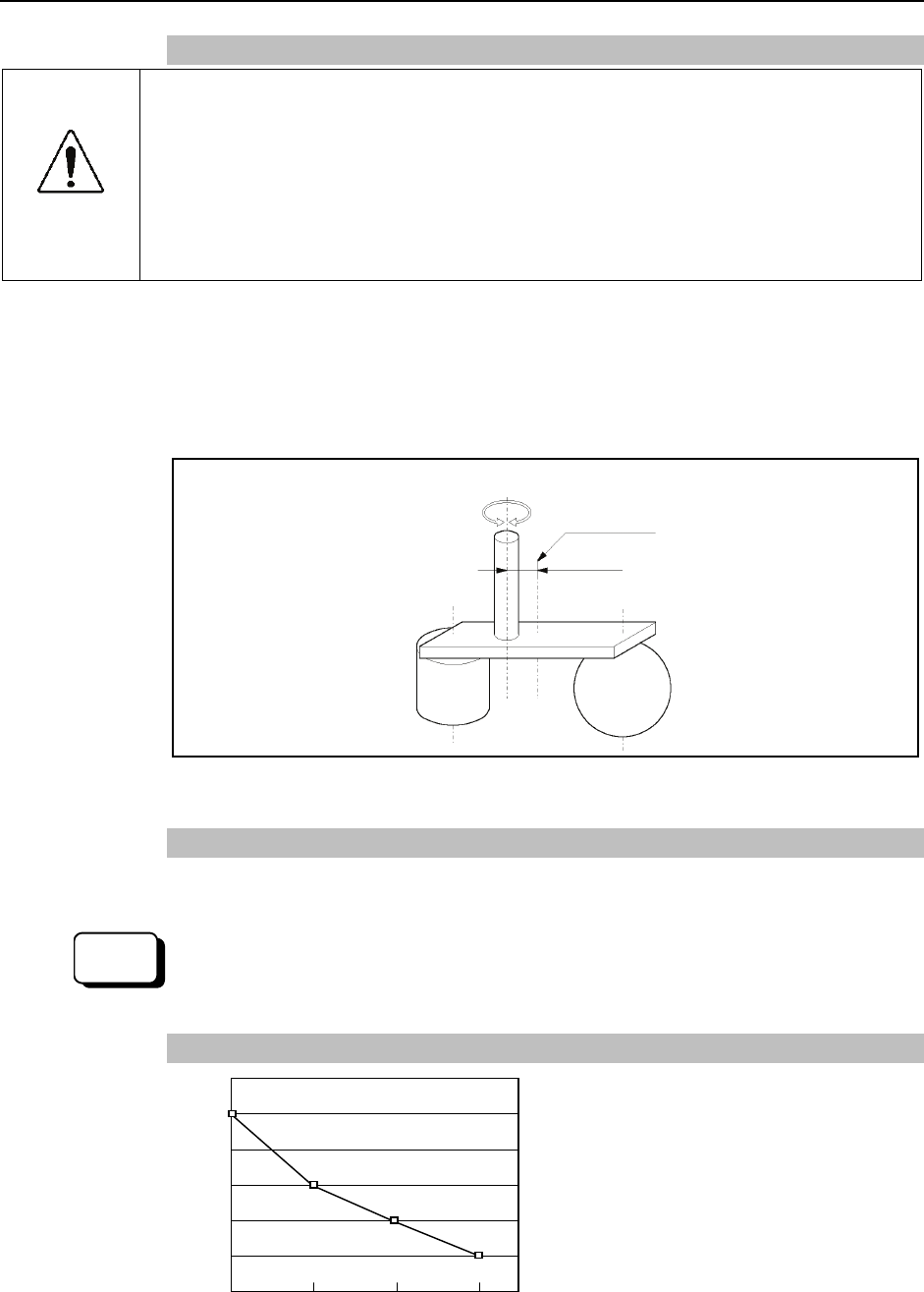
Automatic acceleration/deceleration setting of Joint #4 by Inertia (moment of inertia)
120
100
80
60
40
20
(%) * The percentage in the graph is based
on the acceleration/deceleration at
rated moment of inertia (0.005 kg⋅m2)
as 100%.
100 100
80
50
30
0 0.005 0.01 0.02 0.03 0.04 0.05 (kg・m2) Moment of inertia setting
42 G3 Rev.1
Setup & Operation 4. Setting of End Effectors
Eccentric Quantity and the Inertia Setting
CAUTION
■ The eccentric quantity of load (weight of the end effector and work piece) must be
150 mm or less. The G3 series Manipulators are not designed to work with
eccentric quantity exceeding 150 mm.
Always set the eccentric quantity parameter according to the eccentric quantity.
Setting a value that is smaller than the actual eccentric quantity may cause
errors, excessive shock, insufficient function of the Manipulator, and/or shorten
the life cycle of parts/mechanisms.
The acceptable eccentric quantity of load in G3 series is 0 mm at the default rating and
150 mm at the maximum. When the eccentric quantity of load exceeds the rating, change
the setting of eccentric quantity parameter of Inertia command. After the setting is
changed, the maximum acceleration/deceleration speed of the Manipulator at PTP motion
corresponding to the “eccentric quantity” is set automatically.
Position of load’s center of gravity
Rotation center
Eccentric quantity (150 mm or less)
Eccentric Quantity
Eccentric quantity of load on the shaft
The eccentric quantity of load (weight of the end effector and work piece) on the shaft can
be set by “eccentric quantity” parameter of Inertia command.
EPSON
RC+
Enter a value into the [Eccentricity:] text box on the [Inertia] panel ([Tools] - [Robot
Manager]). (You may also execute the Inertia command from the [Command Window].)
Automatic acceleration/deceleration setting by Inertia (eccentric quantity)
* The percentage in the graph is
based on the acceleration /
deceleration at rated eccentricity
(0 mm) as 100%.
120
100
80
60
40
20
0 50 100 150 (mm)
Eccentricity setting
60
40
20
(%)
100
G3 Rev.1 43
Setup & Operation 4. Setting of End Effectors
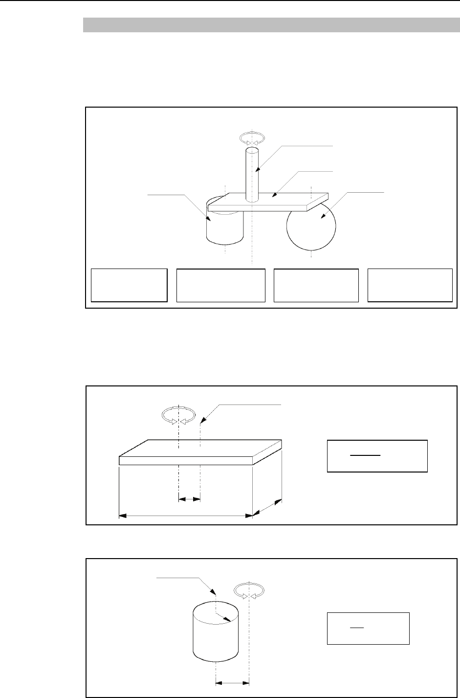
Calculating the Moment of Inertia
Refer to the following examples of formulas to calculate the moment of inertia of load
(end effector with work piece).
The moment of inertia of the entire load is calculated by the sum of each part (a), (b), and
(c).
Work piece (b) Work piece (c)
End effector (a)
Joint #3 shaft
Rotation center
Moment of inertia
of end effector (a)
= Moment of inertia
of work piece (b)
+Moment of inertia
of work piece (c)
+
Whole moment
of inertia
The methods for calculating the moment of inertia for (a), (b), and (c) are shown below.
Calculate the total moment of inertia using the basic formulas.
(a) Moment of inertia of a rectangular parallelepiped
b
L
Mass (m)
Rectangular parallelepiped’s center of gravity
Rotation center
m+ m × L2
b2 + h2
12
h
(b) Moment of inertia of a cylinder
m+ m × L2
r 2
2
Mass (m)
L
r
Cylinder’s center of gravity Rotation center
44 G3 Rev.1
Setup & Operation 4. Setting of End Effectors
G3 Rev.1 45
(c) Moment of inertia of a sphere
m r
2+ m × L2
2
5
Sphere’s center of gravity
r
Mass (m)
Rotation center
L
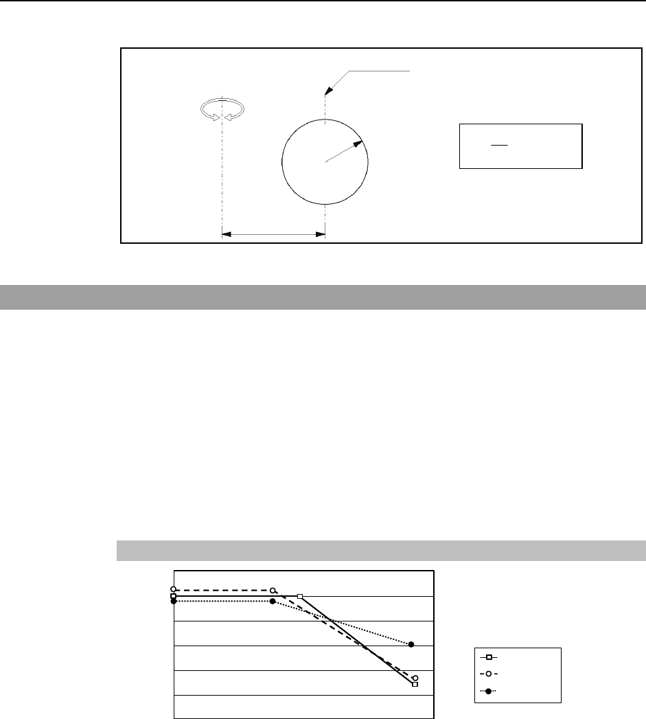
4.4 Precautions for Auto Acceleration/Deceleration of Joint #3
When you move the Manipulator in horizontal PTP motion with Joint #3 (Z) at a high
position, the motion time will be faster.
When Joint #3 gets below a certain point, then auto acceleration/deceleration is used to
reduce acceleration/deceleration. (Refer to the figure below.) The higher the position of
the shaft is, the faster the motion acceleration/deceleration is. However, it takes more
time to move Joint #3 up and down. Adjust the position of Joint #3 for the Manipulator
motion after considering the relation between the current position and the destination
position.
The upper limit of Joint #3 during horizontal motion using Jump command can be set by
the LimZ command.
Automatic acceleration/deceleration vs. Joint #3 position
120
100
80
60
40
20
0 -30 -60 -90 -120 -150 (mm) Shaft height
(%) * Figures on the graph (%) are
the proportion to the
acceleration/deceleration speed
at the shaft upper limit position.
100
60
100 100
30 G3-25***
G3-30***
G3-35***
When moving the Manipulator horizontally while the shaft is being lowered, it may cause
over-shoot at the time of final positioning.
)
NOTE
Setup & Operation 5. Motion Range
5. Motion Range
CAUTION
■ When setting up the motion range for safety, both the pulse range and
mechanical stops must always be set at the same time.
The motion range is preset at the factory as explained in Setup & Operation: 5.4 Standard
Motion Range. That is the maximum motion range of the Manipulator.
There are three methods for setting the motion range described as follows:
1. Setting by pulse range (for all joints)
2. Setting by mechanical stops (for Joints #1 to #3)
3. Setting the Cartesian (rectangular) range in the X, Y coordinate system of the
Manipulator (for Joints #1 and #2)
Mechanical
stop
Rectangular range setting
Pulse range
Motion range Mechanical
stop
When the motion range is changed due to layout efficiency or safety, follow the
descriptions in 5.1 to 5.3 to set the range.
46 G3 Rev.1

Setup & Operation 5. Motion Range
G3 Rev.1 47
5.1 Motion Range Setting by Pulse Range (for All Joints)
Pulses are the basic unit of Manipulator motion. The motion range of the Manipulator is
controlled by the pulse range between the pulse lower limit and upper limit of each joint.
Pulse values are read from the encoder output of the servo motor.
For the maximum pulse range, refer to the following sections.
The pulse range must be set inside of the mechanical stop range.
5.1.1 Max. Pulse Range of Joint #1
5.1.2 Max. Pulse Range of Joint #2
5.1.3 Max. Pulse Range of Joint #3
5.1.4 Max. Pulse Range of Joint #4.
)
NOTE Once the Manipulator receives an operating command, it checks whether the target
position specified by the command is within the pulse range before operating. If the
target position is out of the set pulse range, an error occurs and the Manipulator does not
move.
EPSON
RC+
The pulse range can be set on the [Range] panel shown by selecting [Tools]-[Robot
Manager]. (You may also execute the Range command from the [Command Window].)
Setup & Operation 5. Motion Range
5.1.1 Max. Pulse Range of Joint #1
The 0 (zero) pulse position of Joint #1 is the position where Arm #1 faces toward the
positive (+) direction on the X-coordinate axis.
When the 0 pulse is a starting point, the counterclockwise pulse value is defined as the
positive (+) and the clockwise pulse value is defined as the negative (-).
+Y
+X 0 pulse
B B
A A
Table Top Mounting
Arm Standard -R -L
25 − −
30 −125 ~ 150 / −125 ~ 150 −150 ~ 125 / −150 ~ 125
A
Max. Motion
Range 35
±140 / ±140
−110 ~ 165/ −110 ~ 165 −165 ~ 110 / −165 ~ 110
25 − −
30 −1019449 ~ 6990507
/ −1019449 ~ 6990507
−1747627 ~ 6262329
/ −1747627 ~ 6262329
B
Max. Pulse
Range
35
−1456356 ~ 6699236
/ −1456356 ~ 6699236 −582542 ~ 7427413
/ −582542 ~ 7427413
−2184533 ~ 5825422
/ −2184533 ~ 5825422
Multiple Mounting
Arm Standard -R -L
30 ±115 / ±115 − −
A
Max. Motion
Range 35 ±120/ ±120 −105 ~ 130 / −105 ~ 130 −130 ~ 105 / −130 ~ 105
30 −728178 ~ 5971058
/ −728178 ~ 5971058 − −
B
Max. Pulse
Range 35 −873813 ~ 6116693
/ −873813 ~ 6116693
−436907 ~ 6407965
/ −436907 ~ 6407965
−1165085 ~ 5679787
/ −1165085 ~ 5679787
48 G3 Rev.1
Setup & Operation 5. Motion Range
5.1.2 Max. Pulse Range of Joint #2
The 0 (zero) pulse position of Joint #2 is the position where Arm #2 is in-line with Arm #1.
With the 0 pulse as a starting point, the counterclockwise pulse value is defined as the
positive (+) and the clockwise pulse value is defined as the negative (-).
B B
0 pulse
A A
Table Top Mounting
Arm Standard -R -L
25 ±141 / ±137 − −
30 ±142 / ±141 −135 ~ 150 / −135 ~ 145 −150 ~ 135 / −145 ~ 135
A
Max. Motion
Range 35 ±142 / ±142 −120 ~ 165 / −120 ~ 160 −165 ~ 120 / −160 ~ 120
25 −2566827 ~ 2566827
/ −2494009 ~ 2494009 − −
30 −2585031 ~ 2585031
/ −2494009 ~ 2494009
−2457600 ~ 2730667
/ −2457600 ~ 2639645
−2730667 ~ 2457600
/ −2639645 ~ 2457600
B
Max. Pulse
Range
35 −2585031 ~ 2585031
/ 2585031 ~ 2585031
−2184533 ~ 3003733
/ −2184533 ~ 2912711
−3003733 ~ 2184533
/ −2912711 ~ 2184533
Table Top Mounting
Arm Standard -R -L
30 ±135 / ±135 − −
A
Max. Motion
Range 35 ±142 / ±142 −120 ~ 160 / −120 ~ 150 −160 ~ 120 / −150 ~ 120
30 −2457600 ~ 2457600
/−2457600 ~ 2457600 − −
B
Max. Pulse
Range 35 −2585031 ~ 2585031
/ −2585031 ~ 2585031
−2184533 ~ 2912711
/ −2184533 ~ 2730667
−2912711 ~ 2184533
/ −2730667 ~ 2184533
G3 Rev.1 49
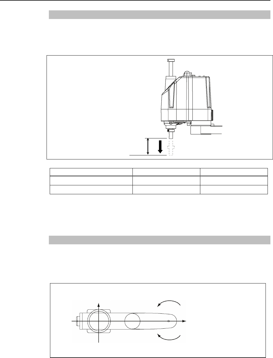
Setup & Operation 5. Motion Range
50 G3 Rev.1
5.1.3 Max. Pulse Range of Joint #3
The 0 (zero) pulse position of Joint #3 is the position where the shaft is at its upper limit.
The pulse value is always negative because Joint #3 always moves lower than the 0 pulse
position.
Upper limit: 0 pulse
Model Joint #3 Stroke Lower Limit Pulse
G3-**1S* 150 mm −1706667
G3-**C* (Cleanroom-model) 120 mm −1365334
For the Cleanroom-model (G3-***C*), the motion range set with the Joint #3 mechanical
stop cannot be changed.
)
NOTE
5.1.4 Max. Pulse Range of Joint #4
The 0 (zero) pulse position of Joint #4 is the position where the flat near the end of the
shaft faces toward the end of Arm #2. With the 0 pulse as a starting point, the
counterclockwise pulse value is defined as the positive (+) and the clockwise pulse value
is defined as the negative (-).
+Y
+X 0 pulse ± 1494221 pulse
Clockwise (-value)
Counterclockwise (+value)
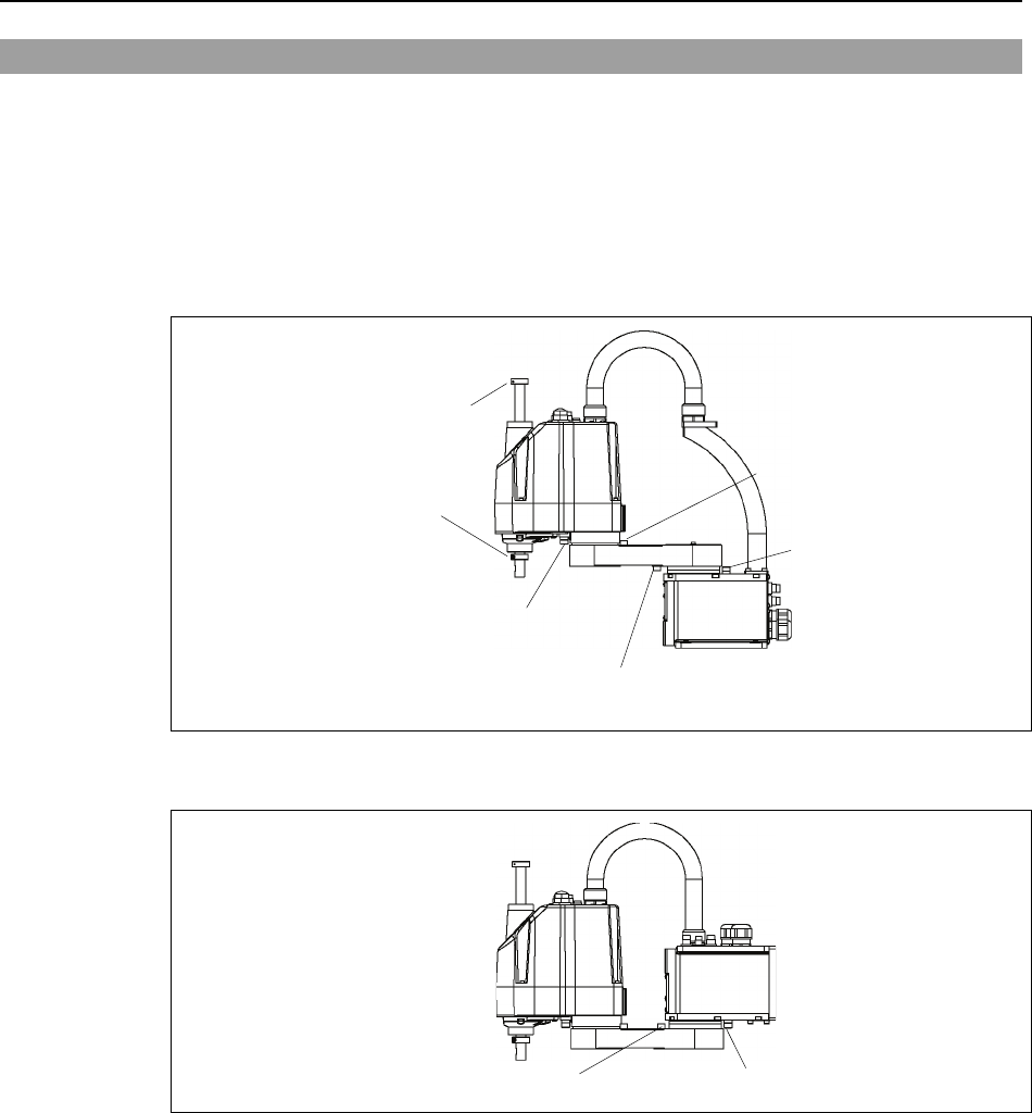
Setup & Operation 5. Motion Range
5.2 Motion Range Setting by Mechanical Stops
Mechanical stops physically limit the absolute area that the Manipulator can move.
Both Joints #1 and #2 have threaded holes in the positions corresponding to the angle for
the mechanical stop settings. Install the bolts in the holes corresponding to the angle that
you want to set.
Joints #3 can be set to any length less than the maximum stroke.
Table Top Mounting
Mechanical stop of Joint #2
(Fixed)
Mechanical stop of Joint #1
(Adjustable)
Mechanical stop of Joint #3
(Lower limit mechanical stop)
(Do not move the upper
limit mechanical stop.)
Mechanical stop of
Joint #1 (Fixed)
Mechanical stop of
Joint #2 (Adjustable)
Multiple Mounting
Mechanical stop of Joint #1 (Adjustable) Mechanical stop of Joint #1 (Fixed)
* The different mechanical stop positions from Table Top mounting are indicated for
Multiple mounting.
G3 Rev.1 51
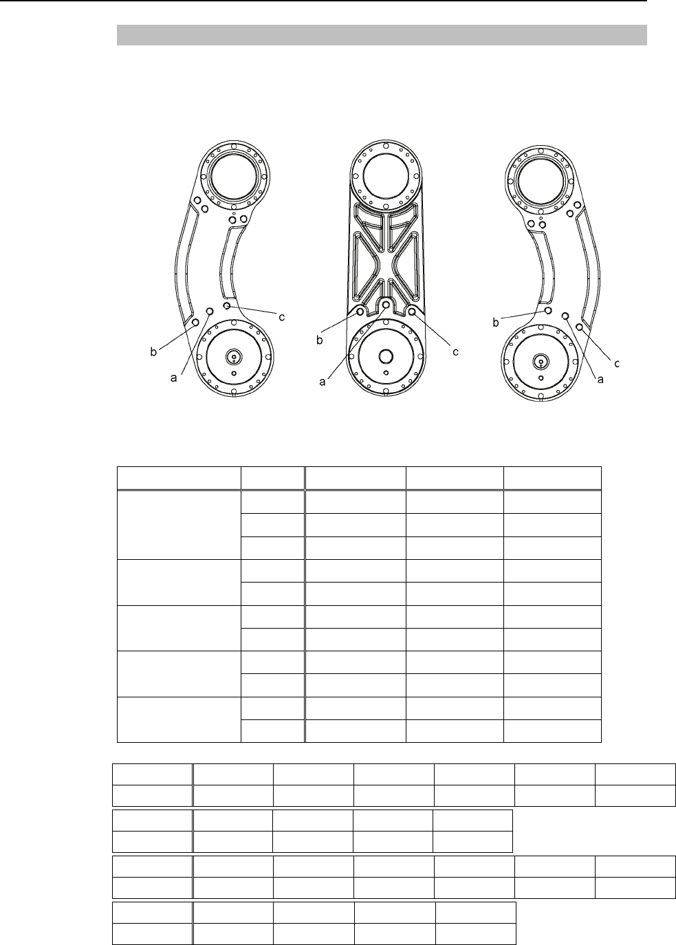
Setup & Operation 5. Motion Range
5.2.1 Setting the Mechanical Stops of Joints #1 and #2
Both Joints #1 and #2 have threaded holes in the positions corresponding to the angle for
the mechanical stop settings. Install the bolts in the holes corresponding to the angle that
you want to set.
R L
Joint #1 Mechanical Stops
Views from the bottom of Arm #1
Model Arm a b c
250 ±140° -110° +110°
300 ±140° -110° +110°
G3-**1S/C
350 ±140° -110° +110°
300 -125° ~ +150°-105° +130°
G3-**1S/C-R 350 -110° ~ +165°-90° +145°
300 -150° ~ +125°-130° +105°
G3-**1S/C-L 350 -165° ~ +110°-145° +90°
300 ±115° -85° +85°
G3-**1SM/CM 350 ±120° -90° +90°
300 -130° ~ +105°-100° +75°
G3-**1SM/CM-R 350 -105° ~ +130°-75° +100°
Setting Angle +75° +85° +90° +100° +105° +110°
Pulse Value 2184533 2475805 2621440 2912711 3058347 3203982
Setting Angle +140° +145° +150° +165°
Pulse Value 4077796 4223431 4369067 4805973
Setting Angle -75° -85° -90° -100° -105° -110°
Pulse Value -2184533 -2475805 -2621440 -2912711 -3058347 -3203982
Setting Angle -140° -145° -150° +165°
Pulse Value -4077796 -4223431 -4369067 -4805973
(°: degree)
52 G3 Rev.1
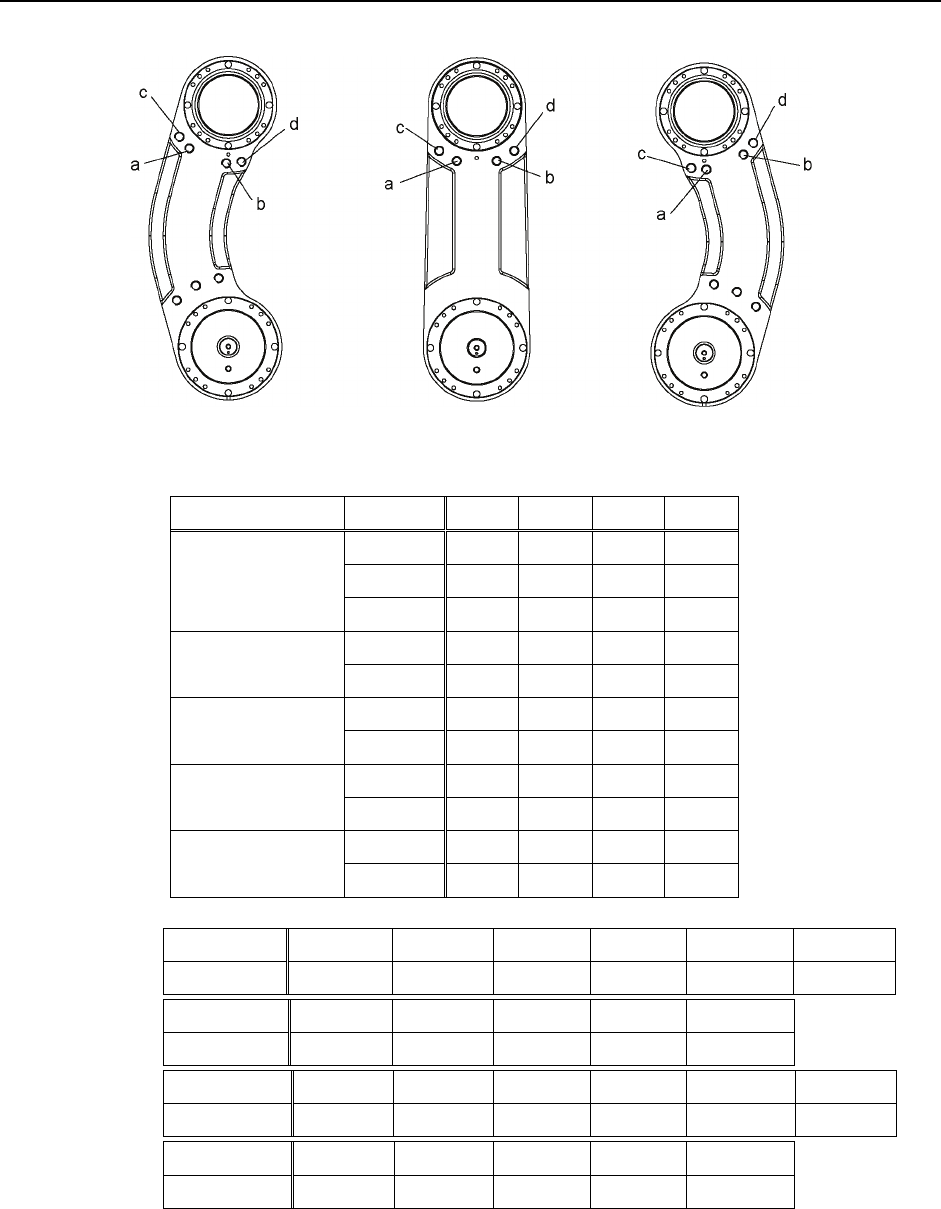
Setup & Operation 5. Motion Range
G3 Rev.1 53
R
L
Joint #2 Mechanical Stops
Views from the top of Arm #1
Model Arm a b c d
250 +141°-141°+120°-120°
300 +142°-142°+122°-122°
G3-**1S/C
350 +142°-142°+122°-122°
300 +150°-135°+135°-120°
G3-**1S/C-R 350 +165°-120°+150°-105°
300 +135°-150°+120°-135°
G3-**1S/C-L 350 +120°-165°+105°-150°
300 +135°-135°+115°-115°
G3-**1SM/CM 350 +142°-142°+122°-122°
300 +120°-160°+100°-140°
G3-**1SM/CM-R 350 +160°-120°+140°-120°
Setting Angle +100° +105° +115° +120° +122° +135°
Pulse Value 2912711 3058347 3349618 3495253 3553508 3932160
Setting Angle +141° +142° +150° +160° +165°
Pulse Value 4106923 4136050 4369067 4660338 4805973
Setting Angle -100° -105° -115° -120° -122° -135°
Pulse Value -2912711 -3058347 -3349618 -3495253 -3553508 -3932160
Setting Angle -141° -142° -150° -160° -165°
Pulse Value -4106923 -4136050 -4369067 -4660338 -4805973
(°: degree)
In case of Multiple Mounting, it is impossible to limit the operating range completely.
Because it may hit the wall within the setting range of mechanical stops.
)
NOTE
Setup & Operation 5. Motion Range
54 G3 Rev.1
(1) Turn OFF the Controller.
(2) Install a hexagon socket head cap bolt into the hole corresponding to the setting angle,
and tighten it.
Joint Hexagon socket head cap
bolt (fully threaded)
The number
of bolts
Recommended
tightening torque
1 M8 × 10 1 bolt /
one side 3720 N⋅cm (380 kgf⋅cm)
(3) Turn ON the Controller.
(4) Set the pulse range corresponding to the new positions of the mechanical stops.
Be sure to set the pulse range inside the positions of the mechanical stop range.
Example: Using G3-251S*
The angle of Joint #1 is set from –132 degrees to +132 degrees.
The angle of Joint #2 is set from -141 degrees to +141 degrees.
)
NOTE
EPSON
RC+
Execute the following commands from the [Command Window].
>JRANGE 1,-9786710,51729750 ' Sets the pulse range of Joint #1
>JRANGE 2,-20534614,+20534614 ' Sets the pulse range of Joint #2
>RANGE ' Checks the setting using Range
-9786710,51729750,-20534614,20534614,-13653338
,0,23907534, 23907534
(5) Move the arm by hand until it touches the mechanical stops, and make sure that the
arm does not hit any peripheral equipment during operation.
(6) Operate the joint changed at low speeds until it reaches the positions of the minimum
and maximum pulse range. Make sure that the arm does not hit the mechanical
stops. (Check the position of the mechanical stop and the motion range you set.)
Example: Using G3-251S*
The angle of Joint #1 is set from -132 degrees to +132 degrees.
The angle of Joint #2 is set from -141 degrees to +141 degrees.
EPSON
RC+
Execute the following commands from the [Command Window].
>MOTOR ON ' Turns ON the motor
>CP ON ' Enters low-power mode
>SPEED 5 ' Sets at low speeds
>PULSE -9786710,0,0,0 ' Moves to the min. pulse position of Joint #1
>PULSE 51729750,0,0,0 ' Moves to the max. pulse position of Joint #1
>PULSE 20971520,-20534614,0,0 ' Moves to the min. pulse position of Joint #2
>PULSE 20971520, 20534614,0,0 ' Moves to the max. pulse position of Joint #2
The Pulse command (Go Pulse command) moves all joints to the specified positions at
the same time. Specify safe positions after considering motion of not only the joints
whose pulse range have been changed, but also other joints.
In this example, Joint #1 is moved to the center of its motion range (pulse value:
20971520) when checking Joint #2.
If the arm is hitting the mechanical stops or if an error occurs after the arm hits the
mechanical stops, either reset the pulse range to a narrower setting or extend the
positions of the mechanical stops within the limit.

Setup & Operation 5. Motion Range
G3 Rev.1 55
5.2.2 Setting the Mechanical Stop of Joint #3
)
NOTE This method applies only to the Standard-model Manipulator (G3-**1S*) / Multiple
Mounting Manipulator (G3-**1SM).
For the Cleanroom-model (G3-**1C*), the motion range set with the Joint #3 mechanical
stop cannot be changed.
(1) Turn ON the Controller and turn OFF the motors using the Motor OFF command.
(2) Push up the shaft while pressing the brake
release button.
Do not push the shaft up to its upper limit or it
will be difficult for the arm top cover to be
removed. Push the shaft up to a position
where the Joint #3 mechanical stop can be
changed.
Shaft
Lower limit
mechanical
stop
2-M5×6
Brake release button
When you press the brake release button, the shaft may lower due to the weight of the
end effector. Be sure to hold the shaft by hand while pressing the button.
(3) Turn OFF the Controller.
(4) Loosen the lower limit mechanical stop screw (M4×15).
A mechanical stop is mounted on both the top and bottom of Joint #3. However, only
the position of the lower limit mechanical stop on the top can be changed. Do not
remove the upper limit mechanical stop on the bottom because the calibration point o
f
Joint #3 is specified using the stop.
(5) The upper end of the shaft defines the maximum
stroke. Move the lower limit mechanical stop
down by the length you want to limit the stroke.
For example, when the lower limit mechanical
stop is set at “150 mm” stroke, the lower limit Z
coordinate value is “-150”. To change the
value to “-130”, move the lower limit
mechanical stop down “20 mm”. Use calipers
to measure the distance when adjusting the
mechanical stop.
Measure
this distance.
(6) Firmly tighten two lower limit mechanical stop screws (M4 × 15) so that they do no
t
enter the shaft groove.
Recommended tightening torque: 490 N⋅cm (50 kgf⋅cm)
(7) Turn ON the Controller.
)
NOTE
)
NOTE

Setup & Operation 5. Motion Range
56 G3 Rev.1
(8) Move Joint #3 to its lower limit while pressing the brake release button, and then chec
k
the lower limit position. Do not lower the mechanical stop too far. Otherwise, the
j
oint may not reach a target position.
(9) Calculate the lower limit pulse value of the pulse range using the formula shown below
and set the value.
The result of the calculation is always negative because the lower limit Z coordinate
value is negative.
Lower limit of pulse = lower limit Z coordinate value / 25 × 4096 × 1.8
Example: When lowering the mechanical stop by 20 mm and changing the lowe
r
limit Z coordinate value to “-130” in 150 mm stroke
(-130) / 25 × 4096 ×1.8= -38339
EPSON
RC+
Execute the following command from the [Command Window].
>JRANGE 3,-38339,0 ' Sets the pulse range of Joint #3
(10) Using the Pulse command (Go Pulse command), move Joint #3 to the lower limit
position of the pulse range at low speed. If the mechanical stop range is less than
the pulse range, Joint #3 will hit the mechanical stop and an error will occur. When
the error occurs, either change the pulse range to a lower setting or extend the position
of the mechanical stop within the limit.
If it is difficult to check whether Joint #3 hits a mechanical stop, turn OFF the
Controller and lift the arm top cover to check the condition causing the problem fro
m
the side.
)
NOTE
Example: When lowering the mechanical stop by 20 mm and changing the lowe
r
limit Z coordinate value to “-130” in 150 mm stroke
EPSON
RC+
Execute the following commands from the [Command Window].
>MOTOR ON ' Turns ON the motor
>SPEED 5 ' Sets low speed
>PULSE 0,0,-38339,0 ' Moves to the lower limit-pulse position of Joint #3.
(In this example, all pulses except those for Joint #3
are “0”. Substitute these “0s” with the other pulse
values specifying a position where there is no
interference even when lowering Joint #3.)

Setup & Operation 5. Motion Range
5.3 Setting the Cartesian (Rectangular) Range
in the XY Coordinate System of the Manipulator (for Joints #1 and #2)
Use this method to set the upper and lower limits of the X and Y coordinates.
This setting is only enforced by software. Therefore, it does not change the physical
range. The maximum physical range is based on the position of the mechanical stops.
EPSON
RC+
Set the XYLim setting on the [XYZ Limits] panel shown by selecting [Tools]-[Robo
t
Manager].
(You may also execute the XYLim command from the [Command Window].)
5.4 Standard Motion Range
The following “motion range” diagrams show the standard (maximum) specification.
When each Joint motor is under servo control, the center of Joint #3’s (shaft’s) lowest
point moves in the areas shown in the figure.
“Area limited by mechanical stop” is the area where the center of Joint #3’s lowest point
can be moved when each joint motor is not under servo control.
“Mechanical stop” sets the limited motion range so that the center of Joint #3 cannot move
beyond the area mechanically.
“Maximum space” is the area that contains the farthest reach of the arms. If the
maximum radius of the end effector is over 60 mm, add the “Area limited by mechanical
stop” and “radius of the end effector”. The total value is specified as the maximum area.
G3 Rev.1 57
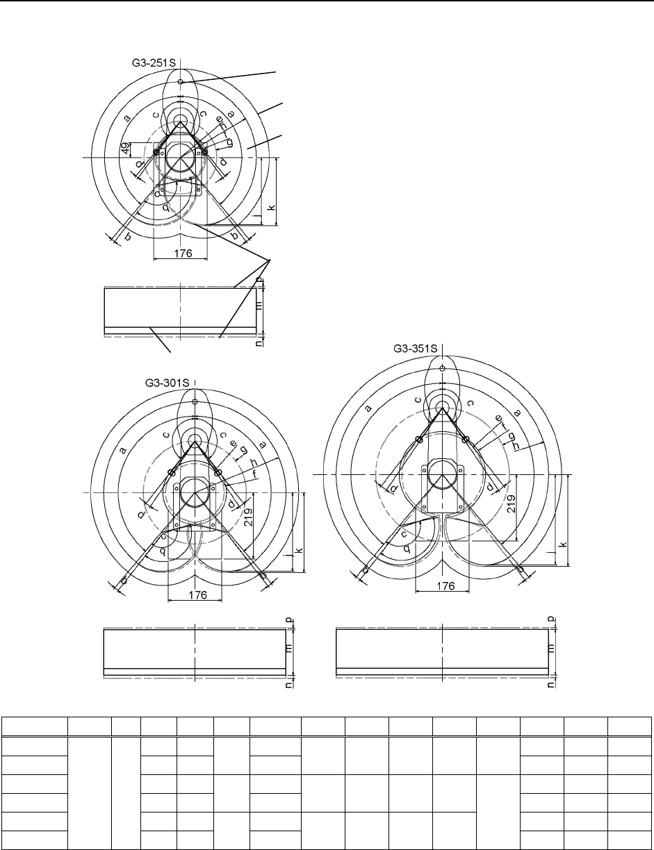
Setup & Operation 5. Motion Range
58 G3 Rev.1
Table Top Mounting - Strait Arm
Center of Joint#3
Maximum space
Motion range
Area limited by mechanical stop
Base mounting face
a b c d e f g h j k q m n p
G3-251S 141° 2.3° 84.0 150 9.6 6.7
G3-251C 137° 6.3° 79.3 92.0 120 250 221.9 224.5 143.3° 120 4.1 10.7
G3-301S 142° 3.8° 104.8 150 9.6 6.7
G3-301C 142° 3.8°
96.2 107.1 170 300 260.2 263.9 120 4.1 10.7
G3-351S 142° 3.8° 142.3 150 9.6 6.7
G3-351C
140° 2°
142° 3.8°
134.
2 146.6 220 350 298.5 303.3
145.8
°
120 4.1 10.7
(°: degree)
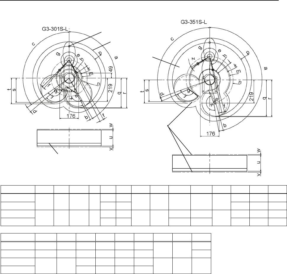
Setup & Operation 5. Motion Range
Table Top Mounting - Left-Curved Arm
Center of Joint#3
Maximum space
Motion range
Area limited
by mechanical stop
Base mounting face
a b c d e f g h j k m n p q
G3-301S-L 150° 3.3° 170 300 277.2
G3-301C-L 150° 3° 125° 6° 145° 8.3° 135° 79.5 86.8 113.2 120.7 277.2
G3-351S-L 165° 2.8° 100.3 183.0 220 350 342.5
G3-351C-L 165° 5° 110° 4° 160° 7.8° 120° 96.9 107.5 184.2 191.6
r s t u v w x y z
G3-301S-L 281.4 227.5 241.5 150 9.6 6.7 -
G3-301C-L 288.7 201.8 227.5 120 4.1 10.7 153.3° 138.3° 3.8°
G3-351S-L 219.4
150 9.6 6.7
G3-351C-L 346.6 205.2
222.9 120 4.1 10.7 167.8° 123.8° 3.8°
(°: degree)
G3 Rev.1 59
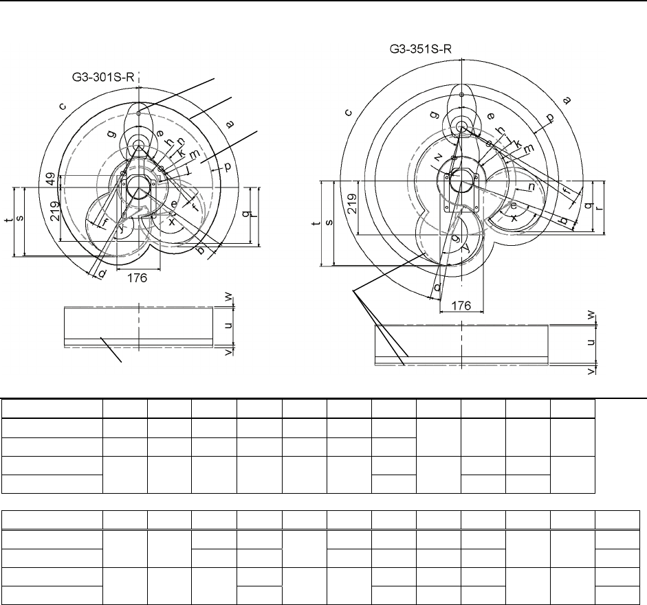
Setup & Operation 5. Motion Range
60 G3 Rev.1
Table Top Mounting - Right-Curved Arm
Center of Joint#3
Maximum space
Motion range
Area limited
by mechanical stop
Base mounting face
a b c d e f g h j k
m
G3-301S-R 125° 6° 150° 3° 135° 3.3° 150°
G3-301C-R 150° 3° 125° 6° 145° 8.3° 145° 79.5 86.8 113.2 120.7
G3-351S-R 165° 100.3 183.0
G3-351C-R 110° 4° 165° 5° 120° 3.8° 160° 96.9 107.5 184.2 191.6
n p q r s t u v w x y z
G3-301S-R 227.5 241.5 281.4 150 9.6 6.7 -
G3-301C-R 170 300
201.8 227.5 277.2 288.7 120 4.1 10.7 138.3° 153.3° 8.3°
G3-351S-R 219.4
150 9.6 6.7 2.8°
G3-351C-R 220 350 205.2
222.9 342.5 346.6 120 4.1 10.7 123.8° 167.8° 7.8°
(°: degree)
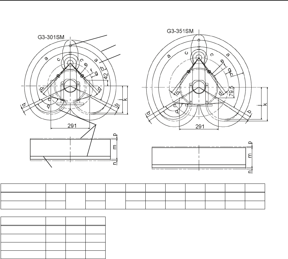
Setup & Operation 5. Motion Range
G3 Rev.1 61
Multiple Mounting : Strait Arm
Center of Joint#3
Maximum space
Motion range
Area limited
by mechanical stop
Base mounting face
a b c d e f g h j k q
G3-301SM/CM 115° 135° 112.0 120.7 170 300 201.8 212.4 138.8°
G3-351SM/CM 120° 4° 142° 3.8° 134.2 142.3 220 350 240.0 253.0 145.8°
m n p
G3-301SM 150 9.6 6.7
G3-301CM 120 4.1 10.7
G3-351SM 150 9.6 6.7
G3-351CM 120 4.1 10.7
(°: degree)
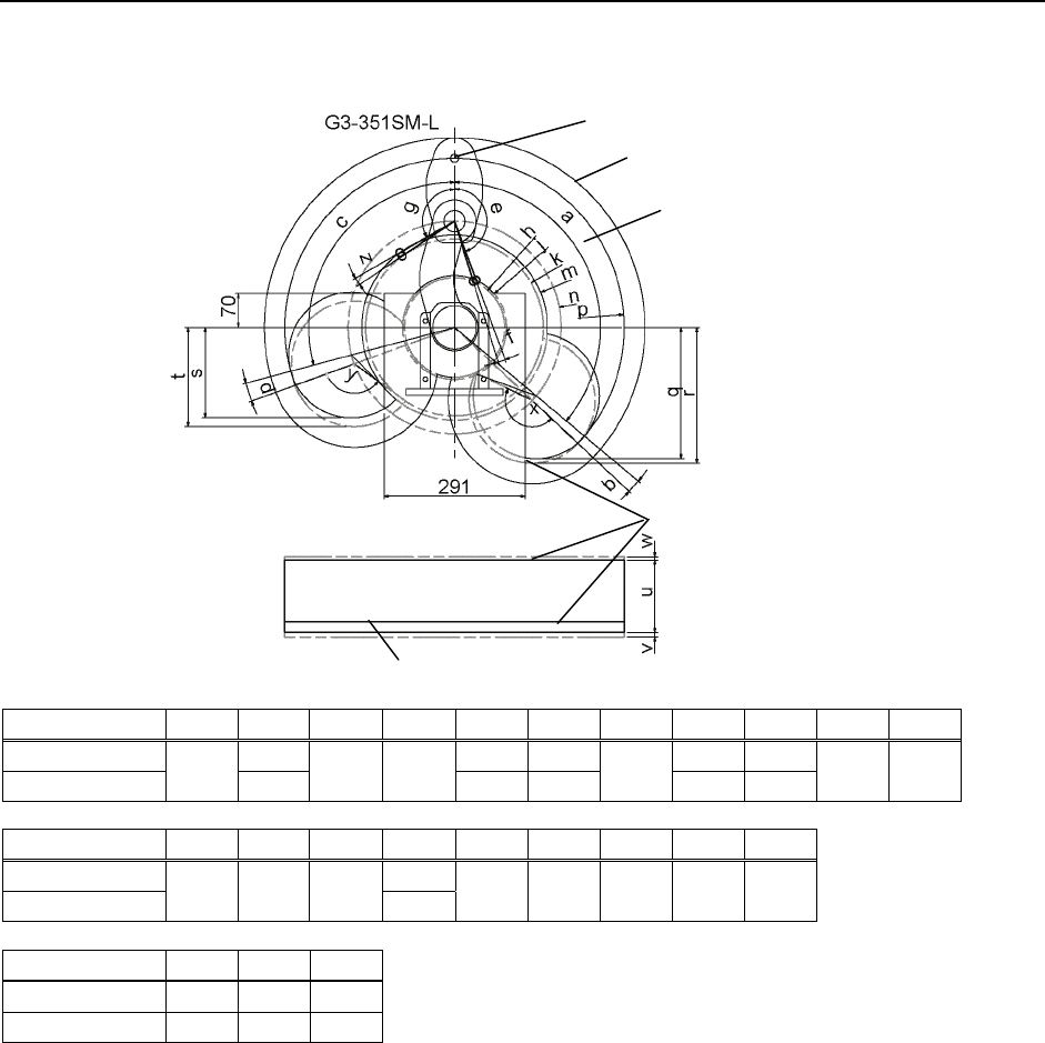
Setup & Operation 5. Motion Range
62 G3 Rev.1
Multiple Mounting : Left-Curved Arm
Center of Joint#3
Maximum space
Motion range
Area limited
by mechanical stop
Base mounting face
a b c d e f g h j k
m
G3-351SM-L 3.3° 160° 2.8° 103.3 125.6
G3-351CM-L 130° 2° 105° 5° 150° 12.8° 120° 125.6 140.5 183.0 191.6
n p q r s t x y z
G3-351SM-L 280.8
G3-351CM-L 220 350 271.4
277.2 186.9 205.2 162.8° 123.8° 3.8°
u v w
G3-351SM-L 150 9.6 6.7
G3-351CM-L 120 4.1 10.7
(°: degree)
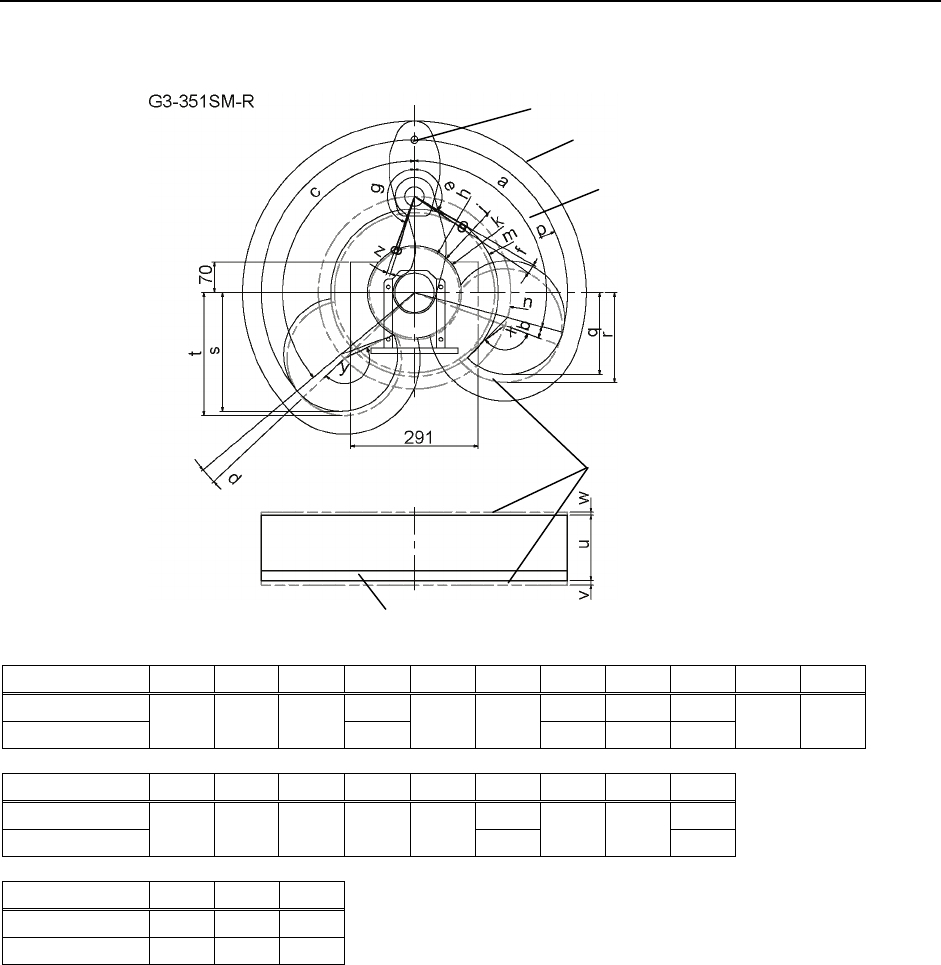
Setup & Operation 5. Motion Range
G3 Rev.1 63
Multiple Mounting : Right-Curved Arm
Center of Joint#3
Maximum space
Motion range
Area limited
by mechanical stop
Base mounting face
a b c d e f g h j k
m
G3-351SM-R 3.3° 160° 103.3 125.6
G3-351CM-R 105° 5° 130° 2° 120° 3.8° 150° 125.6 140.5 183.0 191.6
N p q r s t x y z
G3-351SM-R 280.8 2.8°
G3-351CM-R 220 350 186.9 205.2 271.4 277.2 123.8° 162.8° 12.8°
u v w
G3-351SM-R 150 9.6 6.7
G3-351CM-R 120 4.1 10.7
(°: degree)

Setup & Operation 5. Motion Range
64 G3 Rev.1

Maintenance
This volume contains maintenance procedures with safety
precautions for G3 series Manipulators.
66
Maintenance 1. Safety Maintenance
1. Safety Maintenance
Please read this chapter, this manual, and other relevant manuals carefully to understand
safe maintenance procedures before performing any routine maintenance.
Only authorized personnel who have taken safety training should be allowed to
maintain the robot system.
Safety training is the program for industrial robot operators that follows the laws
and regulations of each nation.
The personnel who have taken safety training acquire knowledge of industrial
robots (operations, teaching, etc.), knowledge of inspections, and knowledge of
related rules/regulations.
The personnel who have completed the robot system-training and maintenance-
training classes held by the manufacturer, dealer, or locally-incorporated
company are allowed to maintain the robot system.
■ Do not remove any parts that are not covered in this manual. Follow the
maintenance procedure strictly as described in this manual. Improper removal
of parts or improper maintenance may not only cause improper function of the
robot system but also serious safety problems.
■ Keep away from the Manipulator while the power is ON if you have not taken the
training courses. Do not enter the operating area while the power is ON.
Entering the operating area with the power ON is extremely hazardous and may
cause serious safety problems as the Manipulator may move even it seems to be
stopped.
■ When you check the operation of the Manipulator after replacing parts, be sure to
check it while you are outside of the safeguarded area. Checking the operation
of the Manipulator while you are inside of the safeguarded area may cause
serious safety problems as the Manipulator may move unexpectedly.
WARNING
■ Before operating the robot system, make sure that both the Emergency Stop
switches and safeguard switch function properly. Operating the robot system
when the switches do not function properly is extremely hazardous and may
result in serious bodily injury and/or serious damage to the robot system as the
switches cannot fulfill their intended functions in an emergency.
■ To shut off power to the robot system, pull out the power plug from the power
source. Be sure to connect the AC power cable to a power receptacle. DO
NOT connect it directly to a factory power source.
WARNING
■ Before performing any replacement procedure, turn OFF the Controller and
related equipment, and then pull out the power plug from the power source.
Performing any replacement procedure with the power ON is extremely
hazardous and may result in electric shock and/or malfunction of the robot
system.
G3 Rev.1 67
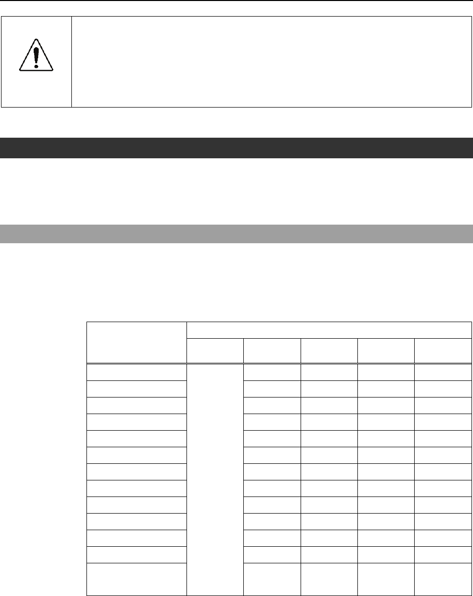
Maintenance 1. Safety Maintenance
68 G3 Rev.1
CAUTION
■ Be sure to connect the cables properly. Do not allow unnecessary strain on the
cables. (Do not put heavy objects on the cables. Do not bend or pull the cables
forcibly.) The unnecessary strain on the cables may result in damage to the
cables, disconnection, and/or contact failure. Damaged cables, disconnection,
or contact failure is extremely hazardous and may result in electric shock and/or
improper function of the robot system.
2. General Maintenance
This chapter describes maintenance inspections and procedures. Performing maintenance
inspections and procedures properly is essential for preventing trouble and ensuring safety.
Be sure to perform the maintenance inspections in accordance with the schedule.
2.1 Schedule for Maintenance Inspection
Inspection points are divided into five stages: daily, monthly, quarterly, biannual, and
annual. The inspection points are added every stage.
If the Manipulator is operated for 250 hours or longer per month, the inspection points
must be added every 250 hours, 750 hours, 1500 hours, and 3000 hours operation.
Inspection Point
Daily
inspection
Monthly
inspection
Quarterly
inspection
Biannual
inspection
Annual
inspection
1 month (250 h) √
2 months (500 h) √
3 months (750 h) √ √
4 months (1000 h) √
5 months (1250 h) √
6 months (1500 h) √ √ √
7 months (1750 h) √
8 months (2000 h) √
9 months (2250 h) √ √
10 months (2500 h) √
11 months (2750 h) √
12 months (3000 h) √ √ √ √
13 months (3250 h)
Inspect every day
√
…
…
…
…
…
…
h = hour

Maintenance 2. General Maintenance
G3 Rev.1 69
2.2 Inspection Point
2.2.1 Inspection While the Power is OFF (Manipulator is not operating)
Inspection Point Inspection Place Daily Monthly Quarterly Biannual Annual
End effector mounting bolts √ √ √ √ √
Manipulator mounting bolts √ √ √ √ √
Each arm locking bolts √ √ √ √ √
Bolts/screws around shaft √
Check looseness or backlash of
bolts/screws.
Tighten them if necessary.
(For the tightening torque, refer to
Maintenance: 2.4 Tightening
Hexagon Socket Head Cap Bolts.)
Bolts/screws securing motors,
reduction gear units, etc. √
External connectors on
Manipulator (on the connector
plates etc.)
√ √ √ √ √
Check looseness of connectors.
If the connectors are loosen, push it
securely or tighten. Manipulator cable unit √ √ √ √
External appearance of
Manipulator
√ √ √ √ √
Visually check for external defects.
Clean up if necessary. External cables √ √ √ √
Check for bends or improper
location. Repair or place it properly
if necessary.
Safeguard etc. √ √ √ √ √
Check tension of timing belts.
Tighten it if necessary. Inside of Arm #2 √ √
Grease conditions Refer to Maintenance: 2.3 Greasing.
2.2.2 Inspection While the Power is ON (Manipulator is operating)
Inspection Point Inspection Place Daily Monthly Quarterly Biannual Annual
Check motion range Each joint √
Move the cables back and forth
lightly to check whether the cables
are disconnected.
External cables
(including cable unit of the
Manipulator)
√ √
Push each arm in MOTOR ON
status to check whether backlash
exists.
Each arm √
Check whether unusual sound or
vibration occurs. Whole √ √ √ √ √
Measure the accuracy repeatedly by
a gauge. Whole √
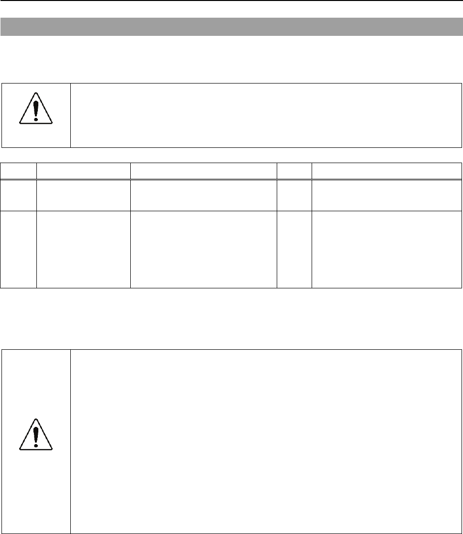
Maintenance 2. General Maintenance
2.3 Greasing
The ball screw spline and reduction gear units need greasing regularly. Only use the
grease specified in the following table.
CAUTION
■ Keep enough grease in the Manipulator. Operating the Manipulator with
insufficient grease will damage sliding parts and/or result in insufficient function of
the Manipulator. Once the parts are damaged, a lot of time and money will be
required for the repairs.
Greasing part Greasing Interval Grease Refer to:
Joint #3 Ball screw spline shaft First time: after 50 km operation
2nd or more: after 100 km operation AFB Maintenance: 10.1 Greasing the Ball
Screw Spline Unit
Joint #1
Joint #2 Reduction gear units In the replacement of motor* SK-1A
Maintenance:
5.2 Replacing the Joint #1 Reduction
Gear Unit
6.2 Replacing the Joint #2 Reduction
Gear Unit
* Under normal conditions, the reduction gear units shall be greased only when the motor is replaced. However, in
case of severe working conditions (such as high duty, high speeds, large payloads, etc.), the reduction gear units
must be greased every 10,000 hours.
CAUTION
■ If grease gets into your eyes, mouth, or on your skin, follow the instructions
below.
If grease gets into your eyes
: Flush them thoroughly with clean water, and then see a doctor
immediately.
If grease gets into your mouth
: If swallowed, do not induce vomiting. See a doctor immediately.
: If grease just gets into your mouth, wash out your mouth with water
thoroughly.
If grease gets on your skin
: Wash the area thoroughly with soap and water.
70 G3 Rev.1
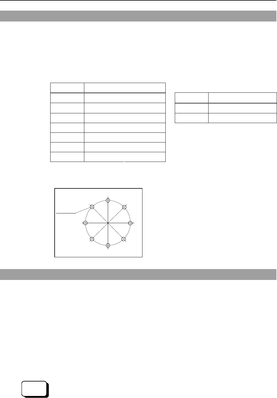
Maintenance 2. General Maintenance
2.4 Tightening Hexagon Socket Head Cap Bolts
Hexagon socket head cap bolts are used in places where mechanical strength is required.
(A hexagon socket head cap bolt will be called a “bolt” in this manual.) These bolts are
fastened with the tightening torques shown in the following table.
When it is necessary to refasten these bolts in some procedures in this manual (except
special cases as noted), use a torque wrench so that the bolts are fastened with the
appropriate tightening torques as shown below.
Bolt Tightening Torque Refer below for the set screw.
M3 245 N⋅cm (25 kgf⋅cm) Set Screw Tightening Torque
M4 490 N⋅cm (50 kgf⋅cm) M4 245 N⋅cm (25 kgf⋅cm)
M5 980 N⋅cm (100 kgf⋅cm) M5 392 N⋅cm (40 kgf⋅cm)
M6 1,760 N⋅cm (180 kgf⋅cm)
M8 3,720 N⋅cm (380 kgf⋅cm)
M10 7,350 N⋅cm (750 kgf⋅cm)
M12 12,740 N⋅cm (1,300 kgf⋅cm)
We recommend that the bolts aligned on a circumference should be fastened in a crisscross
pattern as shown in the figure below.
1
5
3
7
2
6
4
8
Bolt hole
Do not fasten all bolts securely at one time.
Divide the number of times that the bolts are
fastened into two or three and fasten the bolts
securely with a hexagonal wrench. Then, use
a
torque wrench so that the bolts are fastened with
tightening torques shown in the table above.
2.5 Matching Origins
After parts have been replaced (motors, reduction gear units, a brake, timing belts, a ball
screw spline unit, etc.), the Manipulator cannot operate properly because a mismatch
exists between the origin stored in each motor and its corresponding origin stored in the
Controller. After replacing the parts, it is necessary to match these origins.
The method of calibration is different depending on the software used. Refer to
Maintenance: 13. Calibration and follow the steps that pertain to the software you are
using.
For calibration, the pulse values for a specific position must be recorded in advance.
Before replacing parts, select easy point (pose) data from the registered point data to check
the accuracy. Then, follow the steps below to display the pulse values and record them.
EPSON
RC+
Execute the following command from the [Command Window].
>PULSE
PULSE: [Joint #1 Pulse value] pls [Joint #2 Pulse value] pls [Joint #3 Pulse value]
pls [Joint #4 Pulse value] pls
G3 Rev.1 71
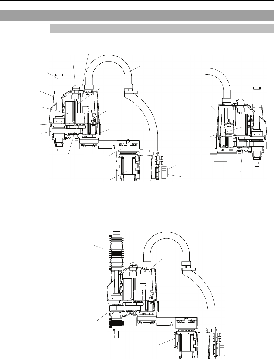
Maintenance 2. General Maintenance
2.6 Layout of Maintenance Parts
2.6.1 Table Top Mounting
G3-**1S : Standard-model
Joint #3
motor
Lithium battery &
Battery board
Joint #1 motor
Joint #2 reduction gear unit
Joint #1
reduction
gear unit
Brake release button switch
Ball screw spline unit
Joint #4 motor
Cable unit
Z belt
U1 belt
Joint #2 motor
Arm cover
U2 belt
Joint #3 brake
(Figure: G3-301S)
LED lamp
Power cable
Signal cable
Joint #3
motor
G3-**1C : Cleanroom-model (with bellows)
Bellows
Gasket
Bellows
Gasket
Heat release sheet
(Figure: G3-301C)
72 G3 Rev.1
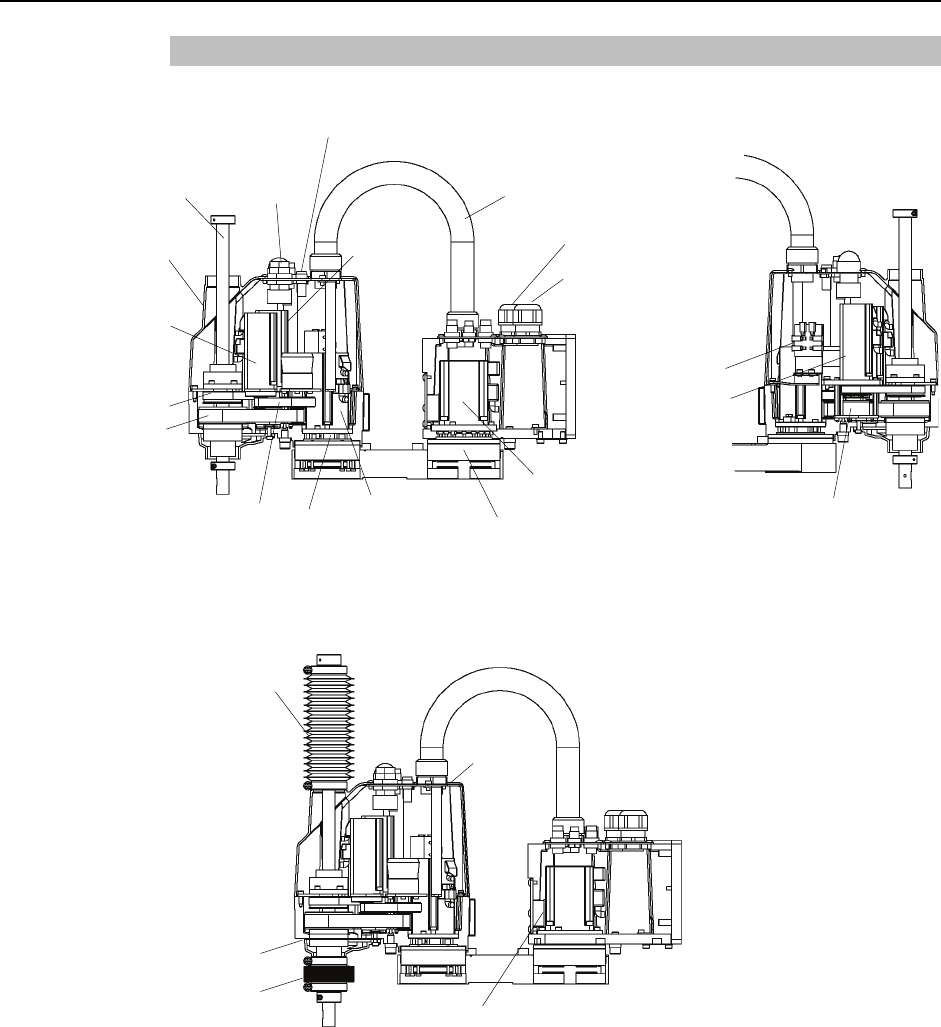
Maintenance 2. General Maintenance
2.6.2 Multiple Mounting
G3-**1SM : Standard-model
Power cable
Cable unit
Joint #3 brake
Lithium batter
y
&
Battery board
Signal cable
Brake release switch
LED lamp
Ball screw
spline unit
Arm cover
Joint #4
motor
Z belt
U1 belt
U2 belt Joint #2
motor
Joint #2
reduction
gear
Joint #1
reduction
gear
Joint #1
motor
Joint #3
motor
Joint #3
motor
(Figure: G3-301SM)
G3-**1CM : Cleanroom-model (with bellows)
Bellows
Gasket
Heat release sheet
Gasket
(Figure: G3-301CM)
Bellows
G3 Rev.1 73
Maintenance 3. Covers
3. Covers
All procedures for removing and installing covers in maintenance are described in this
chapter.
■ Do not insert or pull out the motor connectors while the power to the robot system
is turned ON. Inserting or pulling out the motor connectors with the power ON is
extremely hazardous and may result in serious bodily injury as the Manipulator
may move abnormally, and also may result in electric shock and/or malfunction of
the robot system.
■ To shut off power to the robot system, pull out the power plug from the power
source. Be sure to connect the AC power cable to a power receptacle. DO NOT
connect it directly to a factory power source.
■ Before performing any replacement procedure, turn OFF the Controller and related
equipment, and then pull out the power plug from the power source.
Performing any replacement procedure with the power ON is extremely hazardous
and may result in electric shock and/or malfunction of the robot system.
WARNING
■ Be careful not to get any foreign substances in the Manipulator, connectors, and
pins during maintenance. Turning ON the power to the robot system when any
foreign substances exist in them is extremely hazardous and may result in electric
shock and/or malfunction of the robot system.
Maintenance Parts and Tools
Name Quantity Note
Under cover gasket 1 R13B031226 Only for Cleanroom-model
Maintenance
parts
Silicon adhesive
(for the gasket on the
Connector Plate)
1 R13B031227 Only for Cleanroom-model
Hexagonal wrench
(width across flats: 3 mm) 1 For M4 screw Only for Cleanroom-model
Torque wrench 1
Cross-point screwdriver 1 For bellows
removal Only for Cleanroom-model
Tools
Wiping cloth 1 For wiping
adhesive
74 G3 Rev.1
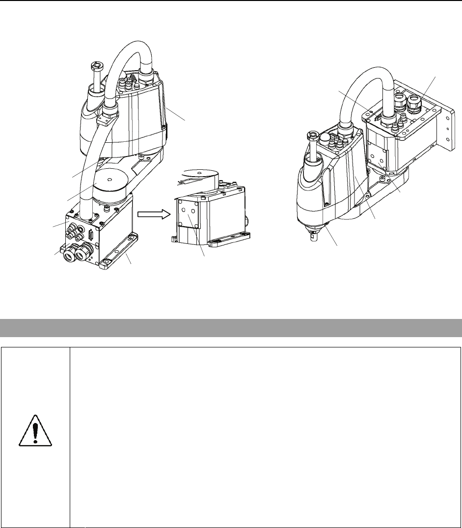
Maintenance 3. Covers
G3 Rev.1 75
Table Top Mounting Multiple Mounting
Arm
bottom cover
Arm cap
Connector
plate
Connector
sub plate Base bottom cover
Arm top cover
Connector plate
Connector
sub plate
Arm top cover
Arm bottom cover
Heatsink plate
Heatsink plate
3.1 Arm Top Cover
■ Do not remove the arm top cover forcibly. Removing the cover forcibly may
result in damage to the cables, disconnection, and/or contact failure. Damaged
cables, disconnection, or contact failure is extremely hazardous and may result in
electric shock and/or improper function of the robot system.
CAUTION
■ When installing the cover, be careful not to allow the cables to interfere with the
cover mounting and do not bend these cables forcibly to push them into the
cover. Unnecessary strain on cables may result in damage to the cables,
disconnection, and/or contact failure. Damaged cables, disconnection, or
contact failure is extremely hazardous and may result in electric shock and/or
improper function of the robot system.
When routing the cables, observe the cable locations after removing the cover.
Be sure to place the cables back to their original locations.
(1) Turn ON the Controller.
Arm Top Cover
Removal (2) Press and hold the brake release button switch to let the shaft down. Be sure to keep
enough space and prevent the end effector hitting any peripheral equipment.
The brake release button switch affects only Joint #3. When the brake release button
switch is pressed, the brake for Joint #3 is released simultaneously.
Be careful of the shaft while the brake release button switch is being pushed
b
ecause it
may be lowered by the weight of an end effector.
)
NOTE
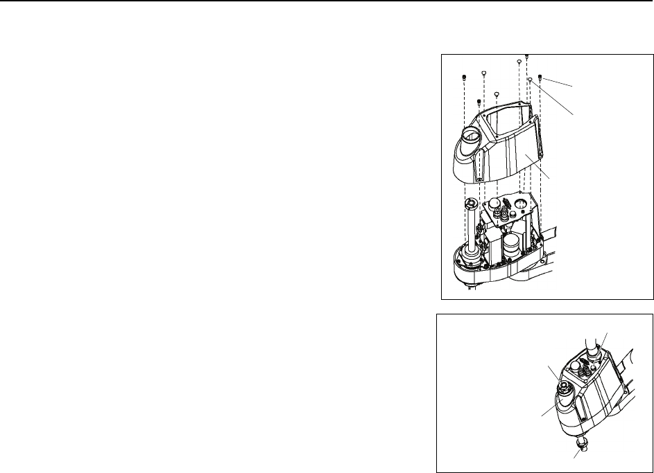
Maintenance 3. Covers
76 G3 Rev.1
(3) Turn OFF the Controller.
(4) Unscrew the arm top cover mounting bolts, and
then lift the cover.
When bellows are installed to the manipulator,
remove the upper bellows and then remove the
arm top cover. For bellows removal, refer to
Maintenance 9. Bellows.
Be careful for user wires and tubes when
removing the cover.
4-M4×12
4-M4×8
Truss
Arm top cover
)
NOTE
Arm Top Cover
Installation
(1) Set the arm top cover to the arm and secure with
the arm top cover mounting bolts.
After mounting the arm top cover, make sure
that the lower limit mechanical stop does not
touch the cylindrical part of the arm top cover.
Arm top cover
Cylindrical part
Shaft
Lower limit
mechanical stop
Brake release switch
(2) When bellows are installed to the manipulator, install the arm top cover and then
install the upper bellows.
For bellows installation, refer to Maintenance 9. Bellows.
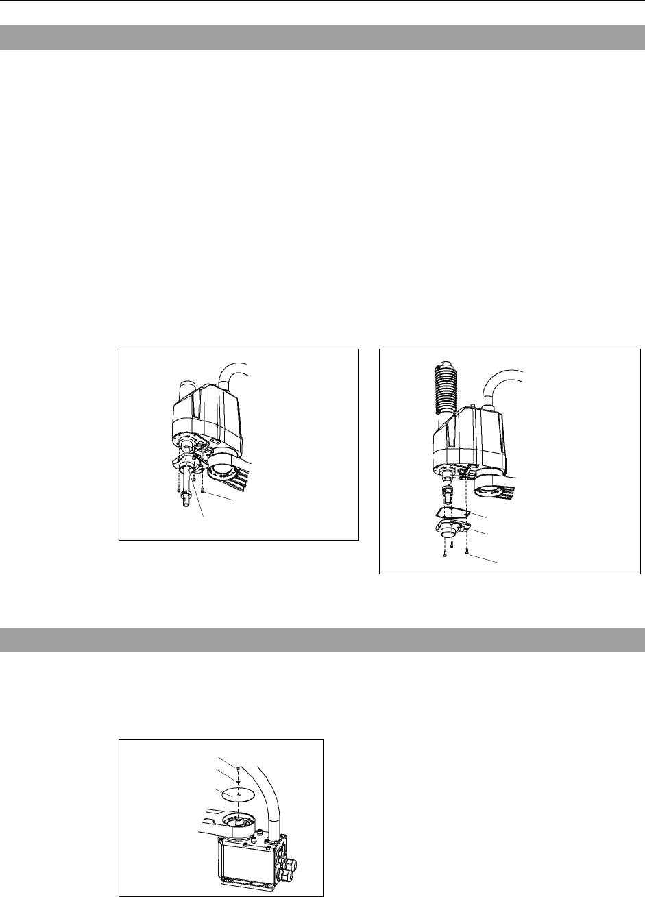
Maintenance 3. Covers
G3 Rev.1 77
3.2 Arm Bottom Cover
Unscrew the arm bottom cover mounting bolts, and then pull the cover downward and
remove it.
The arm bottom cover may not be removed from the shaft because the end effector is
installed.
If it is necessary to remove the cover completely (for replacement of the ball screw spline
unit etc.), remove the end effector.
If it is not necessary to remove the cover completely, move the shaft to the lower limit, an
d
lower the arm bottom cover. Then, perform maintenance or inspection.
When bellows are installed to the manipulator, remove or pull down the lower bellows an
d
then remove the arm bottom cover. For bellows removal, refer to
M
aintenance 9.
Bellows.
)
NOTE
G3-**1S* (Standard-model) G3-**1C* (Cleanroom-model)
3-M4
×
12
Arm bottom cover
Gasket
3-M4×12
Arm bottom cover
A gasket is installed to G3-**1C* (Cleanroom-model).
3.3 Arm Cap
Unscrew the arm cap mounting bolts and remove the cover.
Arm cap is not installed to the Multiple Mounting Manipulators.
G3-**1 Table Top Mounting
M4×8
Arm cap
Flat washer
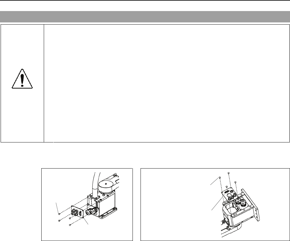
Maintenance 3. Covers
3.4 Connector Plate
■ Do not remove the connector plate forcibly. Removing the connector plate
forcibly may result in damage to the cables, disconnection, and/or contact failure.
Damaged cables, disconnection, or contact failure is extremely hazardous and
may result in electric shock and/or improper function of the robot system.
CAUTION
■ When installing the connector plate, be careful not to allow the cables to interfere
with the plate mounting and do not bend these cables forcibly to push them into
the cover.
Unnecessary strain on cables may result in damage to the cables, disconnection,
and/or contact failure. Damaged cables, disconnection, or contact failure is
extremely hazardous and may result in electric shock and/or improper function of
the robot system.
When routing the cables, observe the cable locations after removing the
connector plate. Be sure to place the cables back to their original locations.
Unscrew the connector plate mounting bolts and remove the plate.
G3-**1* Table Top Mounting G3-**1*W Multiple Mounting
Truss:
4-M4×8
Connector plate
Truss:
4-M4×8
Connector plate
78 G3 Rev.1
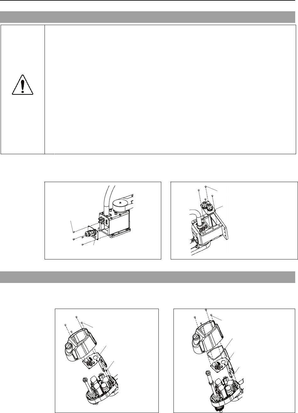
Maintenance 3. Covers
3.5 Connector Sub Plate
■ Do not remove the connector sub plate forcibly. Removing the connector sub
plate forcibly may result in damage to the cables, disconnection, and/or contact
failure. Damaged cables, disconnection, or contact failure is extremely
hazardous and may result in electric shock and/or improper function of the robot
system.
CAUTION
■ When installing the connector sub plate, be careful not to allow the cables to
interfere with the plate mounting and do not bend these cables forcibly to push
them into the cover.
Unnecessary strain on cables may result in damage to the cables, disconnection,
and/or contact failure. Damaged cables, disconnection, or contact failure is
extremely hazardous and may result in electric shock and/or improper function of
the robot system.
When routing the cables, observe the cable locations after removing the
connector sub plate. Be sure to place the cables back to their original locations.
Unscrew the connector sub plate mounting bolts and remove the plate.
G3-**1* Table Top Mounting G3-**1*W Multiple Mounting
Truss:
4-M4×8
Connector sub plate
Truss: 4-M4×8
Connector sub plate
3.6 User Plate
Unscrew the user plate mounting bolts and remove the plate.
G3-**1S* Standard-model G3-**1C* Cleanroom-model
User plate
Truss: 4-M4
×
8
3-M4
×
12
Gasket
Truss: 4-M4×8
3-M4×12
User plate
A gasket is installed to G3-**1C* (Cleanroom-model).
G3 Rev.1 79
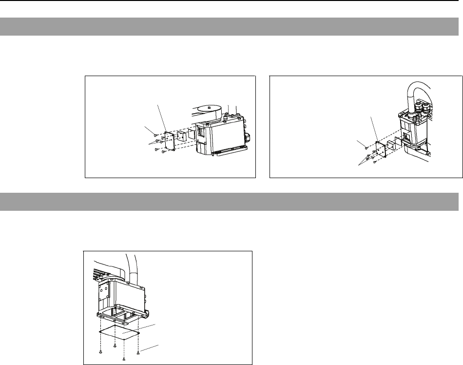
Maintenance 3. Covers
80 G3 Rev.1
3.7 Heatsink Plate
Unscrew the heatsink plate mounting bolts to remove the plate.
G3-**1* Table Top Mounting G3-**1*W Multiple Mounting
Truss:
4-M4
×
8
Heatsink plate
T
russ: 2-M4
×
8
Truss:
4-M4×8
Heatsink plate
Truss: 2-M4
×
8
3.8 Base Bottom Cover
Unscrew the base bottom cover mounting bolts and remove the cover.
G3-**1C* Cleanroom-model
Truss: 4-M4
×
8
Base bottom cove
r
)
NOTE A base bottom cover is not installed to G3-**1S* (Standard-model).

Maintenance 4. Maintenance Parts List
G3 Rev.1 81
4. Maintenance Parts List
4.1 Common Parts
Part Name Code Note
250 mm R13B020023
300 mm R13B020024
S/C
350 mm R13B020025
300 mm R13B020026
Cable Unit
SM/CM 350 mm R13B020027
Cable Length 3 m R12B020431
Cable Length 5 m R12B020432
M/C Cable
Cable Length 10 m R12B020433
Joint #1 R13B000614 200 W
AC Servo Motor Joint #2 / #3 / #4 R13B000615 150 W
Joint #1 R13B010016 SHG20-80
Reduction Gear
Unit Joint #2 R13B010017 SHG17-50
Solenoid Brake Z axis R13B030501
Joint #3 R13B030213 Z :
R13B030214 U1 :
Timing Belt Joint #4 R13B030215 U2 :
Joint #1 R13A030700200 For SHG-20
Joint #2 R13A030700100 For SHG-17
Joint #1 R13A030700700 O-ring20
O-ring
Joint #2 R13A030700600 O-ring17
Brake Release Switch R13Z702640100
Oil seal unit R13B031233
Battery Board R13B041202
With lithium battery
Installed in Arm #2
Battery Unit R13ZA00600300 Lithium battery for replacement
LED Lamp R13A030000200
Ball Screw Spline R13ZA00330200 AFB grease (400 g)
Reduction Gear Unit R13ZA00330100 SK-1A (500 g)
Grease
Cable R13B030304 Tube of GPL-224 (227 g)

Maintenance 4. Maintenance Parts List
82 G3 Rev.1
4.2 Parts by Environment Model
4.2.1 S: Standard-model
Part Name Code Note
Ball Screw Spline 150 mm R13B010220
Arm Cover R13B030421 White
Arm Bottom Cover R13B030423
4.2.2 C: Cleanroom-model
Part Name Code Note
Ball Screw Spline 120 mm R13B010221
Arm Cover R13B030422 Plating
Arm Bottom Cover R13B030424
Bellows R13B030704
Gasket Unit R13B031234
