Epson I Users Manual Apex 110 User
Epson-Epson-Apex-110-Users-Manual-665005 epson-epson-apex-110-users-manual-665005
I+ to the manual 38a2ebee-41b7-49b1-9cbc-17be60128952
2015-01-23
: Epson Epson-I-Users-Manual-251247 epson-i-users-manual-251247 epson pdf
Open the PDF directly: View PDF ![]() .
.
Page Count: 139 [warning: Documents this large are best viewed by clicking the View PDF Link!]
- FRONT MATTER
- TABLE OF CONTENTS
- INTRODUCTION
- CHAP 1-SETTING UP YOUR SYSTEM
- CHAP 2-USING YOUR EQUITY I+
- CHAP 3-INSTALLING OPTION CARDS
- CHAP 4-TROUBLESHOOTING
- APPENDIX A-CHANGING JUMPER SETTINGS
- APPENDIX B-SPECIFICATIONS
- APPENDIX C-GLOSSARY
- INDEX
- DIAGNOSTICS
- FRONT MATTER
- TABLE OF CONTENTS
- INTRODUCTION
- CHAP 1-RUNNING THE DIAGNOSTICS
- CHAP 2-SETTING UP THE SYSTEM
- CHAP 3-FORMATTING A HARD DISK
- CHAP 4-FORMATTING A DISKETTE
- CHAP 5-PERFORMING SYSTEM DIAGNOSTICS
- Using the System Diagnostics Program
- System Board Check
- Memory Check
- Keyboard Check
- Monochrome Display Adapter and CRT Check
- Color Graphics Adapter and CRT Check
- Floppy Disk Drives and Controller Check
- Math Coprocessor Check (8087)
- Parallel Port (Printer Interface) Check
- Parallel Port (on Video Adapter) Check
- Serial Port (RS-232C) Check
- Alternate Serial Port Check
- Dot-matrix Printer Check
- Hard Disk Drives and Controller Check
- CHAP 6-MOVING THE HARD DISK
- CHAP 7-SYSTEM-DEPENDENT UTILITIES
- APPENDIIX A-ERROR CODES AND MESSAGE
- APPENDIX B-POWER-ON DIAGNOSTICS
- INDEX

IMPORTANT NOTICE
DISCLAIMER OF WARRANTY
Seiko Epson Corporation makes no representations or warranties, either express
or implied, by or with respect to anything in this manual, and shall not be liable for
any implied warranties of merchantability and fitness for a particular purpose or
for any indirect, special or consequential damages. Some states do not allow the
exclusion of incidental or consequential damages, so this exclusion may not apply
to you.
COPYRIGHT NOTICE
All rights reserved. No part of this publication may be reproduced, stored in a
retrieval system, or transmitted, in any form or by any means, electronic, mechani-
cal, photocopying, recording or otherwise, without the prior written permission of
Seiko Epson Corporation. No patent liability is assumed with respect to the use of
information contained herein. While every precaution has been taken in the prep-
aration of this publication, Seiko Epson Corporation assumes no responsibility for
errors or omissions. Nor is any liability assumed for damages resulting from the use
of the information contained herein. Further, this publication and features
described herein are subject to change without notice.
TRADEMARKS
Epson is a registered trademark of Seiko Epson Corporation.
Equity is a trademark of Epson America, Inc.
Centronics is a registered trademark of Centronics Data Computer Corp.
Hercules is a trademark of Hercules Computer Technology.
IBM is a registered trademark of International Business Machines Corp.
MS and GW are trademarks of Microsoft Corp.
Copyright © 1986 by Seiko Epson Corporation
Nagano, Japan
ii

FCC COMPLIANCE STATEMENT
FOR AMERICAN USERS
This equipment generates and uses radio frequency energy and if not installed and
used properly, that is, in strict accordance with the manufacturer’s instructions, may
cause interference to radio and television reception. It has been type tested and found
to comply with the limits for a Class B computing device in accordance with the
specifications in Subpart J of Part 15 of FCC
rules,
which are designed to provide
reasonable protection against such interference in a residential installation. However,
there is no guarantee that interference will not occur in a particular installation. If this
equipment does cause interference to radio or television reception, which can be deter-
mined by turning the equipment off and on, the user is encouraged to try to correct
the interference by one or more of the following measures:
l Reorient the receiving antenna
l Relocate the computer with respect to the receiver
l Move the computer away from the receiver
l Plug the computer into a different outlet so that computer and receiver are on
different branch circuits.
If necessary, the user should consult the dealer or an experienced radio/television tech-
nician for additional suggestions. The user may find the following booklet prepared by
the Federal Communications Commission helpful:
“Television Interference Handbook”
This booklet is available from the U.S. Government Printing Office, Washington DC
20402. Stock No. 004-000-00450-7.
Note: If the interference stops, it was probably caused by the computer or its periph-
eral devices. To further isolate the problem:
Disconnect the peripheral devices and their input/output cables one at a time.
If the interference stops, it is caused by either the peripheral device or its I/O
cable. These devices usually require shielded I/O cables. For Epson peripheral
devices, you can obtain the proper shielded cable from your dealer. For non-
Epson peripheral devices contact the manufacturer or dealer for assistance.
WARNING
This equipment has been certified to comply with the limits for a Class B
computing device, pursuant to Subpart J of Part 15 of FCC Rules. Only
peripherals (computer input/output devices, terminals, printers, etc.) certi-
fied to comply with the Class B limits may be attached to this computer.
Operation with non-certified peripherals is likely to result in interference
to radio and TV reception.
The connection of a non-shielded equipment interface cable to this equip-
ment will invalidate the FCC Certification of this device and may cause
interference levels which exceed the limits established by the FCC for this
equipment.
iii
Contents
Introduction
..................................
Intro-1
How to Use This Manual .........................
Intro-2
1
Setting Up Your System
........................
1-1
Unpacking .....................................
1-1
Removing the disk drive protector sheet ...........
1-2
Choosing a Location .............................
1-2
Arranging the Components .......................
1-3
The rear panel ................................
1-4
The front panel ...............................
1-5
Connecting the Power Cord ......................
1-6
Connecting the Video Monitor ....................
1-7
Connecting the Keyboard ........................
1-8
Connecting the Printer ...........................
1-10
Parallel interface
...............................
1-10
Serial interface
................................
1-12
The Equity I+ character set .....................
1-12
Setting the DIP Switches .........................
1-13
DIP switch set 1 (internal operations)
..............
1-14
DIP switch set 2 (parallel and serial
port operations)
.............................
1-16
Turning On the Computer ........................
1-18
Safetyrules.. .................................
1-18
Initial setup procedure
..................
.'
.......
1-19
Initial screen display
............................
1-19
2
Using Your Equity I+
.........................
2-1
Special Keys
....................................
2-1
Selecting Execution Speed
........................
2-2
Resetting the Computer ..........................
2-3
Turning Off the Computer ........................
2-4
Using Disks and Disk Drives ..
.'
...................
2-4
How disks work
...............................
2-5
Choosing diskettes for the Equity I+ ..............
2-5
Caring for your disks and disk drives
..............
2-5
Inserting and removing diskettes
.................
2-7
Write-protecting diskettes
.......................
2-8
V
Making backup copies
..........................
Using a single floppy disk drive
..................
Using a hard disk drive
.........................
3
Installing Option Cards
........................
Removing the Cover.............................
Inserting the Option Card........................
Removing an access slot cover...................
Replacing the Cover.............................
Post-installation Setup
............................
Removing Option Cards.........................
4
Troubleshooting
..............................
4-1
The Computer Fails to Start Up...................
4-1
The Video Display Does Not Appear...............
4-1
The Computer Locks Up or Freezes................
4-2
Floppy Disk Problems
............................
4-2
Hard Disk Problems
.............................
4-3
Software Problems
...............................
4-3
Printer Problems
................................
4-4
Option Card Problems...........................
4-4
Appendixes
A
Changing Jumper Settings
.....................
Jumper J1, Floppy Disk Controller ..................
Jumper J2, Parity RAM...........................
B
Specifications
.................................
MainUnit.....................................
Keyboard
......................................
Mass Storage
...................................
Power Supply
...................................
Environmental Requirements
......................
Physical Characteristics (CPU Only) ................
Video and Display Options.......................
C
Glossary......................................
2-9
2-9
2-10
3-1
3-1
3-3
3-5
3-6
3-7
3-7
A-1
A-1
A-3
Bl
B-1
B-2
B-2
B-2
B-2
B-2
B-3
C-1
Index
......................................
Index-1
vi
Figures
1-1
System arrangement
.............................
1-3
1-2
Rear panel
.....................................
1-4
1-3
Front panel ....................................
1-5
1-4
Inserting the power cord
..........................
1-6
1-5
Connecting the monitor cable .....................
1-7
1-6
Opening the keyboard socket cover .................
1-8
1-7
Connecting the cable to the main unit ..............
1-9
1-8
Adjusting the keyboard legs
.......................
1-10
1-9
Locating the printer .............................
1-11
1-10
Connecting the printer ...........................
1-12
1-11
Location of DIP switches ..........................
1-13
1-12
DIP switch label
.................................
1-14
2-1
Equity I+ keyboard ..............................
2-1
2-2
Speed switch
...................................
2-3
2-3
Inserting diskettes
...............................
2-7
2-4
Write-protect notch ..............................
2-8
2-5
Write-protect switch
.............................
2-9
3-1
Back panel screws
...............................
3-2
Side screws under plastic inserts
....................
3-3
Removing cover.. ...............................
3-4 Inserting option card
.............................
3-5
Removing access slot cover
........................
3-6
Replacing the cover
..............................
A-1 Jumper positions
..............................
3-2
3-2
3-3
3-4
3-5
3-6
A-1
A-2
A-2 Jumper locations ..............................
Tables
1- 1
Monitor/video card compatibility
..................
1-8
1-2
DIP switch set 1
.................................
1-14
1-3
DIP switch set 2
.................................
1-16
2-1
Special key functions .........................................................
2-2
vii
Introduction
Your Epson® Equity™ I+ personal computer is a versatile, expandable,
and economical system. Its flexibility lets you create your own system; first
you choose from three models of the Equity I+ main unit, then you select
the accessories you want to use with it to assemble the configuration that
does the most for you.
The Equity I+ main unit is available in three configurations:
l
One floppy disk drive
l
Two floppy disk drives
l
One floppy disk drive and one internal hard disk drive.
You also choose which monitor you want to use.
Optional cards and external devices further expand the capabilities of
your Equity I+. Its built-in serial and parallel interfaces and five internal
option slots let you connect almost any peripheral device you choose. Here
are some options you can use with your system:
•
•
•
•
•
•
•
•
Expanded memory option card
8087 math coprocessor
Monochrome monitor
Monochrome video card
RGB (red green blue) color or enhanced color monitor
Color/graphics video card (color, monochrome, or enhanced graphics
adapter)
Graphics or enhanced graphics video card
An Epson printer or plotter.
Check with your Epson dealer from time to time to find out which
peripherals and option cards are available. You can use most of the cards
designed for the IBM® personal computer on your Equity I+.
Intro- 1
The Equity I+ comes with the MS™-DOS operating system and the
GW™-BASIC programming language. If you have used MS-DOS before on
another computer, you will find that it works the same on the Equity I+. Be
sure to refer to your Equity MS-DOS manual, however, for descriptions of
the special utility programs added by Epson.
You may have purchased other software as well; you can use most soft-
ware products designed for the IBM PC on your Equity I+. Refer to your
software program documentation for information on using the software.
Additionally, the Equity I+ supports multiple users and multiple tasking
with the appropriate operating system. Consult your Epson dealer for more
information.
How to Use This Manual
This user’s guide explains how to set up and care for your Equity I+. It
also describes how to connect optional equipment and start using your oper-
ating system. You may not need to read everything in this book; some sec-
tions may describe a particular option or accessory you do not have.
Follow the instructions in Chapter 1 to set up your system and turn on
your Equity I+. Chapter 2 covers some of the general operational proce-
dures. It also describes how disks and disk drives work and shows how to use
them. Chapter 3 explains how to install and remove option cards. Chapter 4
provides information on troubleshooting. The appendixes tell you how to
change jumper settings and list hardware specifications. A glossary of some
of the computer terms this guide uses is also included, Refer to the glossary
whenever you come across an unfamiliar term.
Intro-2
Chapter 1
Setting Up Your System
Setting up your Epson Equity I+ personal computer is easy. Just follow
the nine easy steps in this chapter. You should also refer to the “Quick Guide
To Setting up Your Equity I+” reference card.
1
Unpacking
As you remove the components from their cartons, be sure to
inspect each piece. If anything is missing, looks damaged, or seems wrong,
consult your Epson dealer. Be sure to keep your packing materials. They
provide the best protection possible for your computer if you need to move
or ship it later.
•
•
•
•
•
•
When you unpack your Equity I+, you should find the following:
The main unit and power cord
The keyboard with detachable cable
An MS-DOS operating system diskette (version 3.2) with an MS-DOS
manual
A GW-BASIC programming language diskette with a GW-BASIC
manual
A diagnostics and system-dependent utilities diskette and a Diagnostics
manual
This Equity I+ User’s Guide.
In addition to these items, you probably purchased a compatible video
monitor and video card.
You’ll find one registration card with your Equity I+. Fill the card out
now and mail it to Epson. With your registration card on file, Epson can
send you update information.
1-1

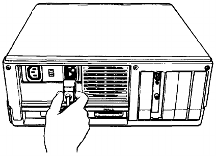
Removing the disk drive protector sheet
A cardboard sheet occupies the disk slot in the floppy disk drive. This
sheet is inserted at the factory to protect the recording read/write heads.
Be sure to remove it before you connect any cables. Press the button on
the left side of the drive. When you release it the edge of the protector sheet
pops out. Carefully pull out this sheet.
Save the protector sheet and reinsert it whenever you move the com-
puter, even if you are just moving it to another part of the room. If you are
not going to use your computer for a week or more, when you go on vacation
for example, reinsert the protector sheet to help keep dust from entering the
disk drive.
2Choosing a Location
An important part of setting up your Equity I+ is deciding where to
locate it. Whether you use your computer at home or in the office, you need
to find a comfortable, convenient location.
Choose a location that provides the following:
A large, sturdy desk or table. Make sure it can easily support the weight
of your system, including all its components.
A flat, hard surface. Soft surfaces like beds and carpeted floors attract
static electricity, which erases data on your diskettes and can damage the
computer’s circuitry. Soft surfaces also prevent proper ventilation.
Good air circulation. Air must be able to circulate freely under the sys-
tem as well as behind it. Leave several inches of space around the com-
puter to allow ventilation.
Moderate environmental conditions. You need to protect your com-
puter from extremes in temperature, humidity, dust, and smoke. Avoid
direct sunlight or any other type of heat. High humidity also hinders
operation, so select a cool, dry area. Because you can’t risk losing data
stored on disk, do not expose your computer to dust and smoke which
can damage disks and disk drives.
Appropriate power sources. To prevent static charges, connect all your
equipment to three-prong, 120-volt grounded outlets. You need one out-
let for the main unit, one for the monitor, and additional outlets for your
printer and any other peripherals. The auxiliary power outlet on the
rear panel of the Equity I+ reduces the number of wall outlets you need.
1-2
lNo electromagnetic interference. Locate your system away from any
electrical device that generates an electromagnetic field. Surprisingly,
even your telephone can cause problems, especially if you keep diskettes
right next to it.
When you find the ideal location for your Equity I+, you can start to set
up your system.
3
Arranging the Components
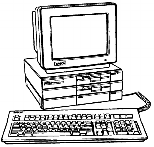
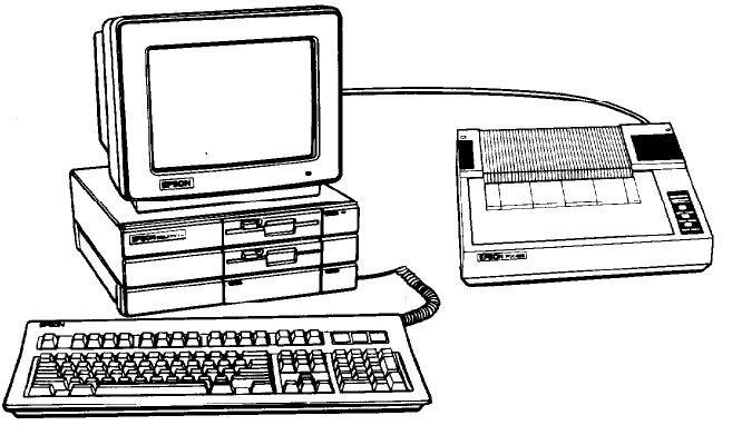
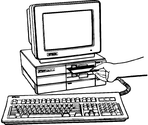
First decide how you want to arrange your system components. The
most common setup, shown in Figure 1-1, is to lay the main unit flat and set
the video monitor on top of it with the keyboard directly in front (leaving
enough space to insert diskettes into the disk drives).
Figure 1-1. System arrangement
Of course, if you have special computer furniture or want to customize
your setup, you can arrange your Equity I+ components to suit your own
particular needs.
1-3
Before you connect the cables, take a look at the rear and front panels of
the main unit.
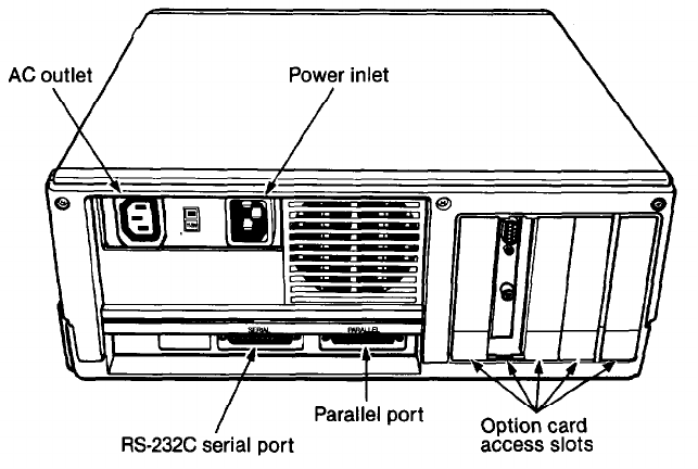
The
rear panel
Look at the rear panel to identify the Equity I+ input/output ports.
Figure 1-2 shows where you connect the peripheral devices.
WARNING: Do not connect the power cord until you have con-
nected all peripheral devices. Always check to see
that the power switch is off before you connect or
disconnect any peripherals.
Figure 1-2. Rear panel
Here are brief descriptions of each of the ports:
l
AC power outlet. Auxiliary power outlet. Some monitors (and other
types of peripherals) can be plugged into the main unit here, instead of a
wall outlet. The main unit’s power switch controls the monitor or
peripheral connected to this outlet. Power consumption should not
exceed 80 watts.
l
AC power inlet. Supplies electrical power to the computer. Always turn
the power switch off before you plug the power cord into an outlet.
1-4
RS-232C serial port. Allows you to connect a peripheral with a serial
interface, such as a modem, another computer or a printer.
Parallel port. Allows you to connect a peripheral with a parallel inter-
face, such as a printer or plotter.
Option card access slots. The Equity I+ has space for five option cards
(which control your peripherals). One of these slots is occupied by either
your monochrome or color/graphics video card. You can use the other
four to add special devices such as a modem or hard disk controller.
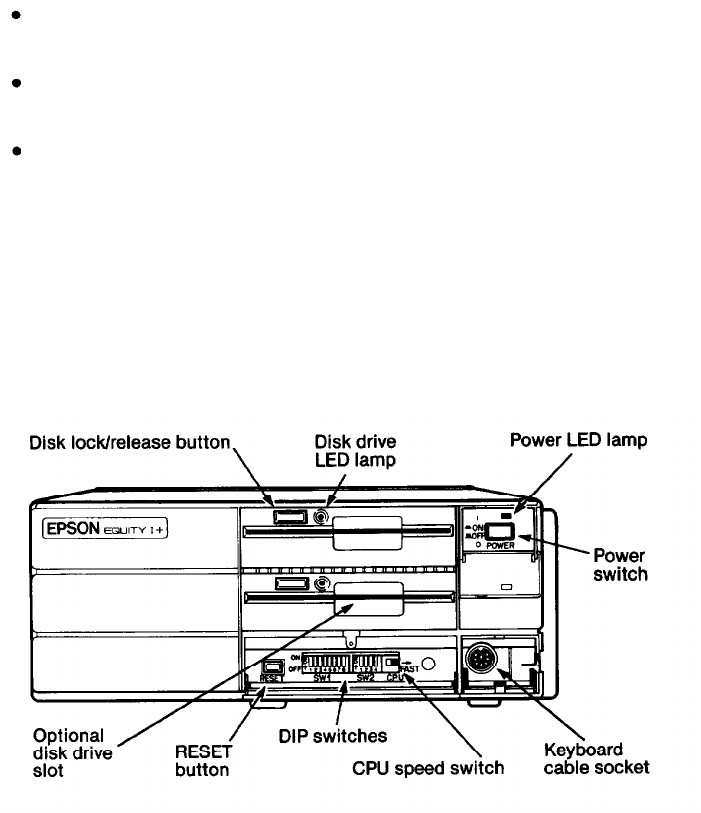
The front panel
Now take a look at the front panel. The components on the front panel
are shown in Figure 1-3 with the covers open to show the switches and the
keyboard cable socket. To open each cover, press down gently on the small
handle.
Figure 1-3. Front panel
The front panel components work as follows:
l
Disk lock/release button. Press to lock a diskette in place. Press again to
eject it.
l
Disk drive LED lamps. A light indicates that the drive is being accessed.
1-5
•
•
•
•
•
•
•
Slot for optional disk drives. You can install a second floppy disk drive or
a hard disk drive in this optional slot. All Equity I+ units come with at
least one floppy disk drive. The main unit above is shown with a second
floppy disk drive.
Power LED lamp. When the light is red the power is on and the system is
running at 4.77MHz. When the light is green the system is on and run-
ning at IOMHz.
Power switch. Turns the main unit on and off.
Keyboard cable socket. The keyboard plugs into the main unit here.
RESET
button. Press this button to reset the computer. When an oper-
ating system diskette is in the top drive or running on the hard disk, you
can press the RESET button to reboot it.
DIP switches. These give the computer information about its keyboard,
coprocessor status, memory size, monitor type, floppy disk drives, and
interface types. You set them to match your system requirements.
CPU Speed switch. Move this switch left for 4.77MHz or right for
10MHz.
4Connecting the Power Cord
Insert the power cord into the AC power inlet on the left side of the
back panel, as shown in Figure 1-4. To avoid an electric shock, be sure to plug
this end into the main unit before plugging the other end into the wall
socket. For now, do not plug the power cord into an electrical outlet.
Figure 1-4. herring the power cord
1-6
5Connecting the Video Monitor
To connect the video monitor, place it on top of or near the
Equity I+ main unit. It is easiest to connect the monitor cable if the backs of
the monitor and the main unit are facing you.
Note: Your dealer probably installed a video card in your main unit to
control your monitor. If not, you need to install it before you can
connect your monitor. See Chapter 3 for installation instructions.
The way you connect your monitor depends on the type you have.
Refer to your monitor manual or follow these guidelines:
1.
If necessary, connect the video monitor cable to your monitor. Some
cables are permanently attached to the monitor at one end.
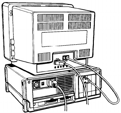
2.
Connect the appropriate end of the video monitor cable to your mono-
chrome or color/graphics card connector at the back of the main unit,
as shown in Figure 1-5. If the plug has retaining screws, tighten them
with a screwdriver.
Figure
1-5. Connecting the monitor cable
The monitor type must match the video card in the main unit. If you
have a color card, you can use either a nine-pin female D-connector for
RGB monitors or an RCA connector for composite video monitors.
Consult Table 1-1 to make sure your card and monitor match. Be sure to
set the switches on the video card to match your monitor.
1-7
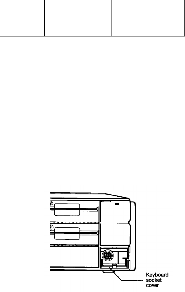
Table 1-1. Monitor/video curd
compatibility
Monitor
Monochrome
Color or
Enhanced color
Video card
output type
Monochrome or graphics
One 9-pin output (TTL
or enhanced graphics
compatible)
Graphics or color graphics
One 9-pin RGB output, or one
or enhanced graphics
RCA-type jack for composite
video
3.
4.
5.
Plug the monitor’s power cable first into the power inlet on the monitor
and then into an electrical outlet. If a monochrome monitor has the
proper type of plug, you can plug it into the auxiliary outlet next to the
power inlet at the back of the main unit. The monitor’s power consump-
tion must not be more than 80 watts.
When you check the DIP switch settings, as defined later in this chapter,
be sure they are set correctly for the type of monitor you have.
If you have trouble getting a display, check that the brightness and con-
trast controls on the monitor are set correctly. Monitors usually have
their own power switches. Make sure the power switch is on.
6Connecting the Keyboard
Follow these steps to connect the keyboard:
1.
Open the cover at the lower right front corner of the main unit, as
shown in Figure 1-6.
Figure 1-6.
Opening
the keyboard socket cover
1-8
2.
Insert the keyboard connector as shown in Figure 1-7. Do not force the
connector, but make sure you insert it all the way. See that the cable exits
to the right of the main unit.
Figure
1-7. Connecting
the
cable
to
the main
unit
3.
Gently push the cable into the retaining clip, and close the cover.
You can use the keyboard at different angles such as laying it flat on a
desk or placing it on your lap. You can also tilt the keyboard by adjusting the
legs on the bottom. Adjust the keyboard legs by turning the keyboard over,
reaching under the lip and pulling each of the legs upward until they lock
into place, as shown in Figure 1-8.
1-9
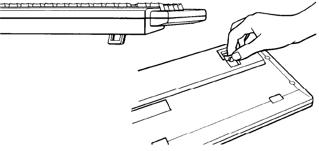
Figure 1-8. Adjusting the keyboard legs
To lower the legs, gently squeeze the sides until they move out of the slot
and push down on the leg until it clicks into place.
To disconnect the keyboard, open the cover on the main unit and press
down on the retaining clip to release the cable. Lift the tab on the connector,
and pull it straight out from the main unit.
7Connecting the Printer
Your Equity I+ has both serial and parallel built-in interfaces. You
can easily connect a printer or plotter that has either a serial or parallel
interface. Just follow the instructions below.
Parallel interface
The parallel connector on the Equity I+ is a Centronic®-compatible
interface with a DB-25 socket. Most Epson printers have a parallel interface.
1-10
To connect your printer to a parallel interface:
1.
Place the printer in a convenient location next to your system, as shown
in Figure 1-9 for example.
2.
3.
4.
Figure 1-9.
Locating the
printer
Before connecting any cables, make sure the power switches on both the
main unit and the monitor are switched off, If you are not sure which
cable you need, consult your dealer.
One end of the printer cable has a 25-pin male D-connector. (Refer to
your printer manual to determine which end this is.) Connect this end
to the socket marked
PARALLEL
on the back panel of the main unit. If
the plug has retaining screws, tighten them with a small screwdriver.
Connect the other end of the cable to the printer. To secure the cable,
tighten the squeeze locks at each side of the printer port and into the
connectors on each side of the cable as shown in Figure 1-10.
1-11
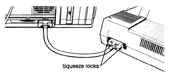
Figure
1- 10. Connecting the printer
5.
Plug the printer’s power cable into a separate electrical outlet.
Serial interface
If you have a printer (or other peripheral, such as a modem) with a serial
interface, connect it to the port marked SERIAL (RS-232C) at the back of
the main unit. If the cable is a non-standard type, with a male D-connector
at both ends, you need an adapter to connect it to the computer. To connect
your serial device, follow the same steps above for connecting a parallel
device.
The RS-232C serial port needs to be configured properly in order for it
to function correctly. The printer output must also be redirected to the serial
port instead of the parallel port. Use the MS-DOS SETMODE utility (or the
MODE command) to make these changes. See your MS-DOS manual for
instructions.
The Equity I+ character set
The Equity I+ uses a special character set that assigns graphics and inter-
national characters to some of the ASCII codes. In most cases, if you try to
print these characters on a standard printer, you get italic characters instead.
Many Epson printers support the IBM character set (like those used on the
Equity I+) as a standard feature, and other printers can be adapted. In addi-
tion, some application programs print the special graphics characters on a
standard printer using a special printer driver program. Ask your dealer for
more information.
1-12
8
Setting the DIP Switches
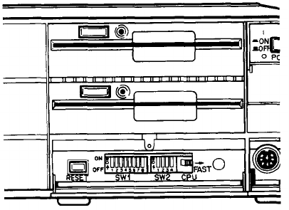
The DIP switches on the Equity I+ are set to provide your system
with information about itself. Each time you turn on your system, it checks
the DIP switch settings to determine the keyboard type, coprocessor status,
memory size, monitor type, number of floppy disk drives, and the typo of
interfaces being used. The DIP switches are located underneath the cover on
the front of your main unit, below the disk drives, as shown in Figure 1-11.
Figure 1-11. Location of DIP switches
Your Epson dealer should have set these switches for you. However, read
this section to be sure the settings match your system configuration. If you
upgrade your computer later (by adding a hard disk drive for example) you
may need to alter the DIP switch settings.
Note: Set the DIP switches only while your computer is off. Software pro-
grams check the settings each time you turn on the system, so do not
change the settings while a program is running.
The Equity I+ has two sets of DIP switches; set 1 contains eight switches
which control the computer’s internal operations, and set 2 contains four
switches which control the parallel and serial ports. A label inside the DIP
switch cover show; the functions of each DIP switch and the factory settings.
See Figure 1-12.
1-13
SWITCH I
1 2 3 4 5 6 7 8
SWITCH II
1 2 3 4
K/B TYPE
ENHANCED
OFF
PARALLEL
PRIMARY
OFF ON
COPROCESSOR
NOT INST
ON
SECONDARY
OFF OFF
RAM SIZE
640KB
OFF OFF
DISABLE
ON ON
512KB
OFF ON
SERIAL
PRIMARY
OFF OFF
256KB
ON ON
SECONDARY
ON OFF
MONITOR TYPE COLOR(40X25)
OFF ON
DISABLE
ON
COLOR(80X25)
ON OFF
MONOCHROME OFF OFF
NO. OF FDD(S)
SINGLE
ON ON
DUAL
OFF ON
Figure 1-12. DIP
switch label
When a switch is up, it is on. When a switch is down, it is off. To change
a setting, use a hard, thin object, such as a small screwdriver.
DIP switch set 1 (internal operations)
The system functions controlled by each switch in set 1 are listed in
Table 1-2 and described below.
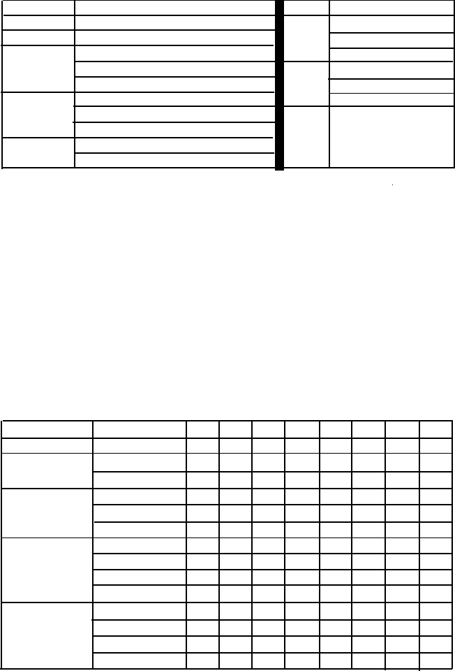
Table 1-2. DIP switch set 1
123 4 5678
Keyboard type
Enhanced
OFF
Coprocessor
Not installed
ON
Installed
OFF
RAM Size
640KB
OFF
OFF
512KB
OFF ON
256KB
ON
ON
Monitor and
Color(40X25)
OFFON
adapter type
Color(80X25)
ONOFF
Monochrome
OFF
OFF
Enhanced
ON
ON
Number of
1
ON
ON
floppy disk 2
OFF
ON
drives 3
ON
OFF
4
OFF
OFF
1-14
Switch 1
(keyboard)-tells your computer what kind of keyboard is attached
to your system. The factory setting is off for the standard (enhanced) key
board which comes with your Equity I+.
Switch
2 (coprocessor)-tells your computer whether or not an optional math
coprocessor is installed. The factory setting is on to tell the system that this
option has not been installed.
Switches 3 and 4 (memory size)-indicate how much built-in memory is avail-
able. These switches should never be changed unless you install a memory
card and you want to use part of the optional memory instead of the built-in
main memory.
The system always checks the amount of available memory each time it is
reset. Problems may occur if the switch settings do not agree with the
amount of main memory in use.
Switches
5 and 6
(monitor
type)--define what type of video card and monitor
you are using and help the system address the adapter memory correctly. Set
these switches as follows:
l
If you have a monochrome monitor and video card, set both switches
Off.
l
If you have an enhanced graphics adapter set both switches on, no mat-
ter what type of monitor you have.
l
If you have a color graphics adapter and an RGB monitor, set switch 5
on and switch 6 off.
l
If you are using a composite video monitor, and its resolution is poor,
you may want to set switch 5 off and switch 6 on. This selects 40-column
text mode for your screen and improves the resolution.
Switches 7
and
8 (floppy disk drive&indicate how many floppy disk drives
your system has. These switches are very important and should be set as
follows:
l
If you have a single drive, set both switches on so the operating system
knows that it must provide help when disk B: is required.
l
If you have two floppy disk drives, set switch 7 off and switch 8 on so the
lower drive is not ignored.
lIf you add external floppy disk drives, for a system total of four, set
switches 7 and 8 as indicated in Table 1-2.
1-15

DIP switch set 2 (parallel and serial port operations)
The parallel and serial port functions controlled by DIP switch set 2 are
listed in Table 1-3 and described below.
Table 1-3. DIP switch set 2
1 2 34
Parallel
Primary
OFF
ON
Secondary
OFF
OFF
Disable
ON
ON
Serial
Primary
OFF
OFF
Secondary
ON OFF
Disable
—
ON
Switches 1, 2, 3,
and 4 tell the computer how to access the built-in parallel
and serial ports. You do not need to change the factory settings unless you
install an option card with an additional parallel or serial port. If you do
install such an option card, read the following information carefully.
Switches 1 and 2 (parallel port)-tell the computer how to access the built-in
parallel port.
The built-in parallel port functions as either the primary or secondary
parallel port. However, if you install any option card with its own parallel
port, you must set these two DIP switches so there is no conflict between the
built-in parallel port and the added card. Table 1-3 shows you how to set the
DIP switches.
If you install an option card that has only a parallel port, you must
designate this as the secondary port and leave the built-in port as the pri-
mary port.
If you install a video card with a parallel port (such as an IBM mono-
chrome display and printer adapter) you must designate it as the primary
parallel port and the built-in port becomes the secondary parallel port.
If you install two option cards with parallel ports, one is designated as
the primary port and the other as the secondary port. In this case, you need
to set switches 1 and 2 on in order to disable the built-in port.
If MS-DOS searches the system for a parallel port and finds only one, it
names it LPTl:. If there are two parallel ports, it names the primary port
LPTl: and the secondary LPT2:.
1-16
Switches 3 and 4 (serial port)-tell the computer how to access the built-in
serial port.
The built-in serial port functions as either the primary or secondary
serial port. However, if you install any option card with its own serial port
you must set these two DIP switches so there is no conflict between the built-
in serial port and the added card. Table 1-3 shows how to set the DIP
switches.
If you install an option card with a serial port preset as primary by the
manufacturer, you must designate it as the primary port and designate the
built-in port as the secondary port.
If you install an option card or peripheral with a serial port not pre-set
you must designate it as the secondary serial port and the built-in port as the
primary serial port.
If you install two option cards with serial ports, one is designated as the
primary port and the other as the secondary port. In this case you need to set
switch 4 on to disable the built-in port.
If MS-DOS searches the system for a serial port and finds only one, it
names it COM1:. If there are two serial ports, it names the primary port
COMl: and the secondary COM2:.
1-17
9Turning On the Computer
After you set up your system, you’re ready to turn on the power and
start using your Equity I+. But before you do turn it on, read the following
safety rules.
Safety rules
1.
Never turn the computer on or off with a disk drive protector sheet in
the disk drive.
2.
3.
4.
5.
6.
7.
Do not attempt to dismantle any part of the computer. Only remove the
top cover to install and remove option cards. If there is a hardware
problem you cannot solve after reading Chapter 4 on troubleshooting,
or if you want to install an optional 8087 math coprocessor, consult your
Epson dealer.
To install or remove option cards, always turn off the power, disconnect
the main power cord, and wait for a few minutes before removing the
cover from the computer.
Do not unplug cables from the computer while the power switch is on.
Never turn off or reset the computer when one of the drive lamps is on.
This can destroy data stored on a disk or make a whole disk unusable.
Always wait at least five seconds after you switch the power off before
switching it on again. Turning it off and on rapidly can damage the
computer’s circuitry.
Never leave a beverage on top of, or next to, your system or any of its
components. Spilled liquid damages the circuitry of your components.
Now you are ready to turn on your system. It’s a good idea to turn on
the monitor and any peripheral devices before you turn on the main unit.
First, make sure the power cord is plugged into the power inlet on the
back panel of the main unit. Then plug the power cord into a three-prong,
120-volt, grounded electrical outlet. Turn on the monitor so you can see the
messages that appear as your computer starts up. If you have a printer or
other peripheral device, turn it on next.
1-18
You can turn on your computer with or without a system diskette in the
top disk drive. For now, leave the drive empty. When you are ready to turn
on the computer, press the power switch at the upper-right corner once. The
power indicator on the front panel lights up and the cooling fan inside the
main unit starts. After a few seconds, the computer begins to perform an
internal test.
If you cannot see the screen display clearly, use the controls on your
monitor to adjust the brightness and contrast until characters on the screen
are clear and bright. If the display is not stable, check your monitor’s hori-
zontal and vertical hold controls.
Initial setup procedure
If this is the first time your Equity I+ has been used, you need to use the
diagnostics diskette to perform an initial setup. This is a simple procedure
which you must do at least once. You may need to do it again if you change
your system time or date or serial port options. See your Diagnostics manual
for instructions.
Initial screen display
After the computer completes its self test, a message tells you how much
RAM (random access memory) is available, for example:
640KB OK
Then the following message displays:
Non-system disk or disk error
Insert system diskette in drive A:
and strike any key when ready.
This tells you that the computer can now load an operating system from a
diskette in the top drive. The Equity I+ needs a disk operating system (DOS)
to function. It comes with MS-DOS version 3.2. If you want to use another
operating system, consult your Epson dealer.
To load an operating system, insert the system diskette you want to use
(see “Inserting and removing diskettes” in Chapter 2). Refer to your
MS-DOS (or other operating system) manual for details on how to use the
system.
Note:
Use only a backup copy of the system diskette for daily use and keep
the original in a safe place. See your MS-DOS manual to find out
how to make a backup copy.
1-19
If your system has a hard disk, you need to prepare it before you can run
an operating system on it. Refer to “Using a hard disk drive” in Chapter 2
(and to your Diagnostics and MS-DOS manuals) for instructions on how to
prepare a hard disk for use.
If your hard disk has been properly prepared and set up to automatically
boot MS-DOS, the message above does not appear. Instead, the operating
system loads when you turn on the computer. The date and time prompts
display and then the system prompt:
C>
This indicates that the hard disk has been assigned as drive C.
1-20
Chapter 2
Using Your Equity I+
Once you have set up your Equity I+, you’re ready to take advantage of
its versatility. This chapter describes the special keys on the keyboard, how to
change your computer’s operating speed, and how to reset and turn off your
computer. It also explains how to use and care for your disks and disk drives.
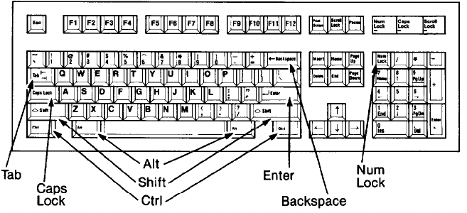
Special Keys
Certain keys serve special functions and are used in various ways by
application programs. Some of the more important keys are shown in Figure
2-1. Table 2-1 describes each of these keys as well as others with special
functions.
Figure 2-1. Equity I+ keyboard
2-1
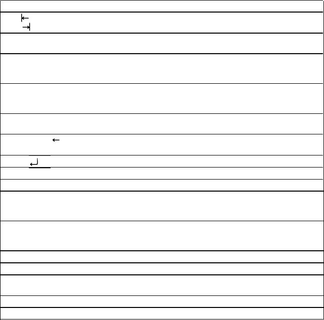
Table
2-1. Special
key
functions
Key
Purpose
Tab
Moves the cursor to the right in normal mode (and to
the left in shift mode in some application programs).
Caps Lock Changes the letter keys from lower- to uppercase;
changes back to lowercase when pressed again.
Shift Produces uppercase characters or symbols when used
with the main character keys. Produces lowercase
characters when
Caps Lock
is on.
Ctrl Works with other keys to perform special (control)
functions, such as editing operations in MS-DOS and
GW-BASIC.
Alt Works with other keys to enter alternate character
codes not otherwise available on a standard keyboard.
Backspace
Moves the cursor back one space, deleting the
character to the left.
Enter
Ends a line of keyboard input or executes a command.
Insert (Ins) Turns insert function on and off.
Delete (Del)
Deletes characters to the right.
Home, End,
Within application programs, control cursor location.
Page Up (Pg Up),
Page Down (Pg Dn)
Num Lock Changes the function of the numeric/cursor keys from
numeric to cursor positioning; changes when pressed
again.
Esc
Cancels the current command line or operation.
F1 - F12 Perform special functions within application programs.
Print Screen Prints the screen display on a line printer.
(Prt
SC
)
Scroll Lock Controls scrolling in some applications.
Pause
Suspends current operation.
The
Num Lock, Scroll Lock,
and
Caps Lock
keys work as toggles
when you press them. When the function is enabled, the corresponding light
on the upper-right corner of the keyboard is on. When the function is
disabled, the light is off.
Selecting Execution Speed
The Equity I+ can operate at two execution speeds: 4.77MHz or 10
MHz. The first speed is IBM compatible. At the second and faster speed the
Equity I+ simply performs all tasks faster. You can select the slower speed to
run application programs that have specific timing requirements.
2-2
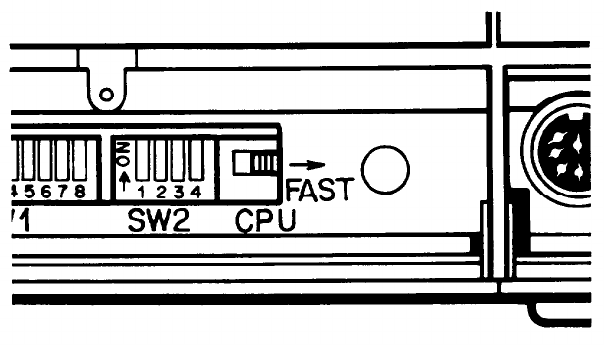
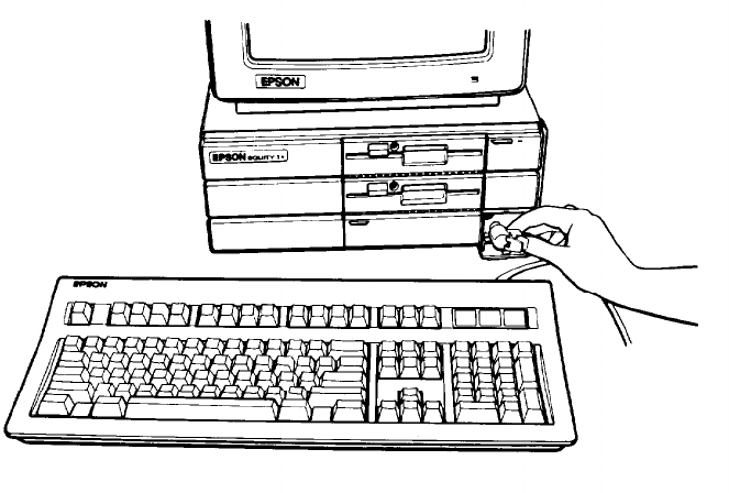
To change the speed, move the switch on the front panel as shown in
Figure 2-2. To run the computer at 4.77MHz, move the switch to the left. To
run it at 10 MHz, move the switch to the right. You can do this at any time
without rebooting the system.
Figure 2-2.
Speed switch
The power light on the front panel is red when the computer is running
at 4.77MHz and green when it is running at 10MHz.
Resetting the Computer
You may occasionally need to reset the computer, either to load a differ-
ent operating system, or because a program has failed and the computer does
not respond to your keyboard commands. However, resetting the computer
causes all data in the computer’s temporary memory (RAM) to be lost, so if
you have a problem, you should reset the computer only as a last resort.
WARNING: Do not reset the computer to exit a program unless
you have to. Some application programs classify and
store new data whenever you exit the program prop
erly. If you reset the computer while such a program
is running, you may lose data.
2-3
There are three ways to reset; you should use them in this order:
1.
If you are using MS-DOS, press Ctrl and
Alt
together with the
Del
key
on the numeric keypad at the right of the keyboard. The screen goes
blank for a moment, and any system disk in drive A reloads. If the
problem is not corrected after trying this, try the second method.
2.
Press the
RESET
button under the hinged flap beneath the disk drives.
This method works even when the keyboard is not responding. If this
fails to have any effect, try the third method.
3.
Remove any diskettes from the disk drives. Turn off the monitor and
any peripherals, and then switch the Equity I+ off. Wait for five seconds,
then switch the power back on.
Turning Off the Computer
Before you turn off your computer, save your data, exit the program you
are using, and remove all diskettes from the disk drives. Turn off the monitor
and peripherals and then turn off the main unit, using the switch on the
front panel.
Using Disks and Disk Drives
The disk drives in your computer let you store your work and programs
on removable diskettes for future use. All Equity I+ systems have at least one
disk drive; others may also have a hard disk drive, either built-in or as an
external unit.
This section gives you some background information on how disks work
and tells you how to:
l
Choose floppy disks (diskettes)
l
Care for your disks and disk drives
l
Insert and remove diskettes
l Write-protect your data
l
Make backup copies
l
Use a single floppy disk drive
l
Use a hard disk drive.
2-4
How disks work
The floppy disks (diskettes) you insert in your system’s floppy disk drives
are round pieces of flexible plastic coated with magnetic material and
enclosed in protective jackets. Like a record, a diskette has circular tracks on
both sides. The computer stores the data you enter as magnetic patterns on
these circular tracks.
A small read/write head in the disk drive interprets the magnetic pat-
terns. When a diskette is in a drive, the read/write head is right over the
large oval hole in the diskette jacket. This hole allows the read/write head to
access the diskette when you store, retrieve, and delete data.
Unlike a floppy disk, a hard disk is rigid and fixed in place. It is sealed in
a protective environment free of dust and dirt, so you cannot see it. A hard
disk stores data the same way as a floppy disk, only it works faster and has a
much larger storage capacity.
Because data is stored magnetically, you can retrieve it, record over it,
and erase it - just as you play, record, and erase music on cassette tapes.
Choosing diskettes for the Equity I+
The standard floppy disk drive on the Equity I+ uses double-sided,
double-density, 48 TPI (tracks per inch) diskettes. These disks are compatible
with those used for the IBM PC. You can use diskettes prepared and used
with one IBM-compatible computer on the other.
For best results, use only high-quality diskettes with reinforced hub
rings-the added reliability is well worth the extra cost. Be sure to select
diskettes that are double-sided, double-density. Each diskette can hold
360KB of data, the equivalent of about 150 pages of text.
If you have an optional floppy disk drive that has a capacity of 720KB,
use
31/2”,
double-sided, highdensity, 135 TI’I diskettes. Each high-density
diskette holds 720KB of data, approximately 300 pages of text.
Caring for your disks and disk drives
To avoid damaging diskettes and hard disks, you need to care for them
properly. Follow these basic precautions to avoid losing data:
l
Keep disks away from dust and dirt. Small particles of dust or dirt
scratch the magnetic surface (destroying data). Dust can also ruin the
read/write head in the disk drive.
2-5
l
l
l
l
l
l
l
l
l
l
Keep disks away from magnetic fields. (Remember that disks store their
information magnetically) There are many sources of magnetism in and
around your home or office, such as electrical appliances and tele-
phones, and particularly loudspeakers.
Keep disks in a moderate environment. They work best at normal room-
temperature and humidity conditions. Never leave them sitting in the
sun, or in extreme cold or heat. The temperature inside a car in the
middle of summer or winter can cause severe damage.
Never touch the diskette’s magnetic surface. The oils on your fingertips
can damage the surface of the disk. Always hold disks by their protective
jackets. On a 720KB diskette, do not expose the diskette’s surface by
sliding the metal plate.
Store diskettes properly. Keep them in their protective envelopes when
they are not in use, and store them in a diskette container.
Do not place anything on top of your disks. They bend easily and do not
rotate properly in their sleeves if they are damaged.
Never wipe, brush, or try to clean diskettes in any way.
Be careful when you label your diskettes. Attach labels firmly but gently,
and only along the top of the disk (next to the manufacturer’s label).
Avoid placing several labels on top of one other. They may prevent the
diskette from spinning freely in the disk drive.
It is best to write on the label before placing it on the disk. Use only soft-
tip pens, not ballpoint pens or pencils, to write on a label that is already
attached to a disk.
Do not remove a diskette or turn off the computer while the drive light is
on. This light indicates that the computer is copying data to or from a
disk. If you interrupt this process, you can destroy data.
Remove all diskettes before you turn off the computer.
If you have a hard disk drive, you should also take these additional precau-
tions:
l
Never turn off the power to the computer when the hard disk LED lamp
is on. This LED indicates that the computer is in the middle of reading
from or writing to the disk. If you interrupt this process, you can lose
data.
2-6
l
Never attempt to open the hard disk unit. The disk itself is enclosed in
an air-tight container to protect it from dust.
lIf you plan to move the hard disk unit, the read/write head must be
moved away from the disk recording area. The MS-DOS program to
protect the read/write head is HDSIT. Refer to your Diagnostics or
MS-DOS manual for details.
Inserting and removing diskettes
To insert a diskette into a disk drive, hold it with the label face up and
the write-protect notch to the left (so that the read/write slot is away from
you). Then slide it into the disk drive as shown in Figure 2-3. Be careful not
to force the diskette into the slot. When it is all the way in, push in the disk
lock/release button to secure the diskette in the drive. This enables the
read/write heads to access the diskette.
Figure 2-3.
Inserting diskettes
To remove the diskette, press the button again. As you release it, the
labelled edge of the diskette pops out. Carefully pull out the diskette, place it
in its protective envelope and store it properly,
2-7
Note: You need to format your blank diskettes before you can use them
with your operating system. Refer to your MS-DOS or other operat-
ing system manual for instructions on how to format your blank
diskettes.
There are two ways to avoid losing the valuable information stored on
your disks; write-protect your diskettes and make backup copies. Both of
these methods are described below.
Write-protecting diskettes
You can write-protect a diskette to prevent its data from being altered.
When a dikette is write-protected, you can copy data from it, but you cannot
store new data on the diskette or delete any files it contains. If you try to
change data stored on a write-protected diskette, an error message displays.
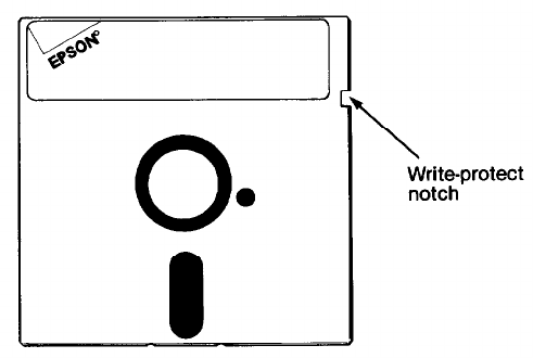
To write-protect a 5%” diskette, cover the small, rectangular notch-
shown in Figure 2-4, with an adhesive write-protect tab. Write-protect tabs
usually come with new 5%” diskettes when you buy them.
Figure 2-4. Write-protect
notch
To unwrite-protect a 5¼” diskette, remove the write-protect tab.
On a 3½” diskette, the write-protect device is a small switch on the
lower-right corner on the back, shown in Figure 2-5. To write-protect this
diskette, slide the switch down toward the edge, of the diskette so there is a
hole where the switch used to be.
2-8
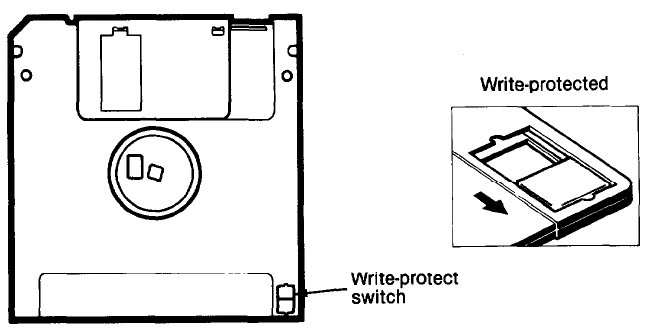
Figure 2-5. Write-protect
switch
To unwrite-protect a 3½” diskette, move the switch up toward the center
of the diskette so the hole is covered.
Making backup copies
It is a good idea to make copies of all your important data and program
diskettes. With program diskettes, or the system master diskette supplied
with your Equity I+, you should use backup copies, and keep the originals in
a safe place-away from your working disks. Copy your data disks regularly
(preferably daily), and keep them apart from the originals.
Your MS-DOS manual describes how to make a backup of your
MS-DOS system disk. To make regular backups of other MS-DOS disks, use
the DU (Disk Utility) program or the DISKCOPY command.
“Using a hard disk drive,” below, gives more information on how to
back up hard disks.
Using a single floppy disk drive
Some Equity I+ systems have only one floppy disk drive. For the com-
puter to function correctly, it needs to know how many floppy disk drives it
has. DIP switches 1-7 and 1-8 tell the computer how many disk drives it has.
If your computer has only one drive, set both switches on. If it has two floppy
disk drives, set switch 1-7 off and switch 1-8 on.
2-9
An operating system expects the computer to have at least two physical
disk drives. MS-DOS recognizes drives A and B for two floppy disk drives, or
A and C for a floppy and a hard disk drive. Some operations, such as copy-
ing files from one disk to another, require two drives. With MS-DOS, if you
have only one physical disk drive, the operating system lets you treat it logi-
cally as two drives.
For example, if you give a command to copy from drive A to drive B,
MS-DOS copies from the first diskette you place in the drive (A) to the
computer’s memory. Then it prompts you to insert the disk for drive B. It
copies from memory to the B disk you place in the drive. When the copy is
complete, the screen prompts you to reinsert the original diskette in drive A.
You may be swapping diskettes this way quite often, and it is easy to
forget which disk is which. To avoid accidentally losing your data, here is a
tip for keeping the disks straight: always hold the disk for drive A in your left
hand and the disk for drive B in your right. Another way to avoid writing on
the wrong disk is to write-protect your source disk. This allows you to read
information, but not write over it.
For more information on using a single floppy disk drive with MS-DOS,
see your MS-DOS manual.
Using a hard disk drive
The Epson hard disk for Equity I+ has a capacity of 20 megabytes-
about 20 million characters. This is equivalent to around 60 floppy disks.
Using the hard disk greatly reduces the number of floppy disks you need and
eliminates much of the disk-swapping you have to do. You can do almost all
your work on the hard disk and copy your files to diskette as needed (to
make backups, for example).
Although it has a lot of storage space, you should keep only the files you
use regularly on the hard disk, to make sure you always have plenty of space
available. Store your other files on diskette (you can use the ARCHIVE
utility or BACKUP command in MS-DOS to back up your hard disk files).
It is very important to back up all your hard disk files on floppy disks. The
hard disk is very reliable, but you should always have backup copies in case
you lose any of your data from the hard disk.
You need to prepare your hard disk before you can use it. If you are using
a hard disk other than Epson’s, follow the preparation instructions provided
with your hard disk.
2-10
Before you use the Epson internal hard disk, you must do the following
things to prepare it:
lUse the Format Hard Disk program on your diagnostics diskette to
format the hard disk.
l
Partition the hard disk to run the MS-DOS operating system using the
MS-DOS program FDISK.
l
Format the MS-DOS partition with the MS-DOS program SELECT.
l
Copy the MS-DOS utility programs to the hard disk using SELECT
For instructions on running the diagnostics program, see your Diagnos-
tics manual. For instructions on how to use the MS-DOS programs, refer to
your MS-DOS manual. If you plan to use an operating system other than
MS-DOS, you also need to use that operating system to partition the hard
disk and copy the system files to it.
Note: Your MS-DOS manual states that you need to run the Setup pro-
gram on the diagnostics diskette before you format the hard disk, but
you do not do this on the Equity I+.
2-11
Chapter 3
Installing Option Cards
Option cards are accessories you can add to your Equity I+ to provide
extra system capabilities. For example, you may want to install a memory
expansion card or an auto-dial modem.
You can install up to five option cards in the Equity I+ at one time, but
one position is always occupied by the video card that operates your moni-
tor.
Option cards are available from Epson as well as other vendors. In addi-
tion, multifunction boards (available from other vendors) allow you to add
other features without using additional slots. Consult your Epson dealer for
more information.
Before you install an option card in your main unit, you need to remove
the cover from your Equity I+.
This chapter describes how to:
l
Remove and replace the main unit’s cover
l
Install and remove an option card.
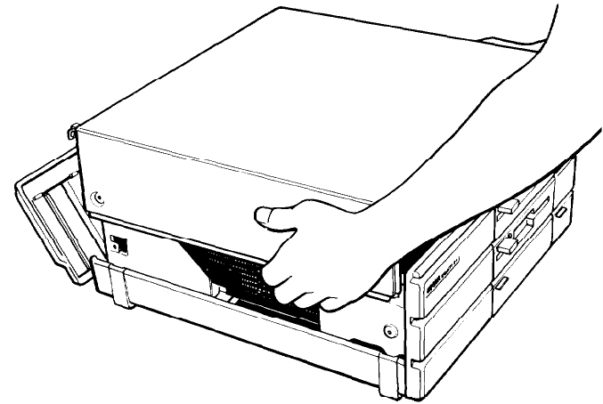
Removing the Cover
WARNING: Never open the case of the Equity I+ while it is
plugged into an electrical outlet. Turn off the power
switch to the main unit and any other peripheral
devices connected to it, wait for a few minutes, then
unplug the power cable before removing the case.
1.
If the monitor is on top of the computer, disconnect it and move it to
one side. Disconnect the keyboard and set it out of the way too. Turn
the main unit around so that the back panel faces you.
3-1
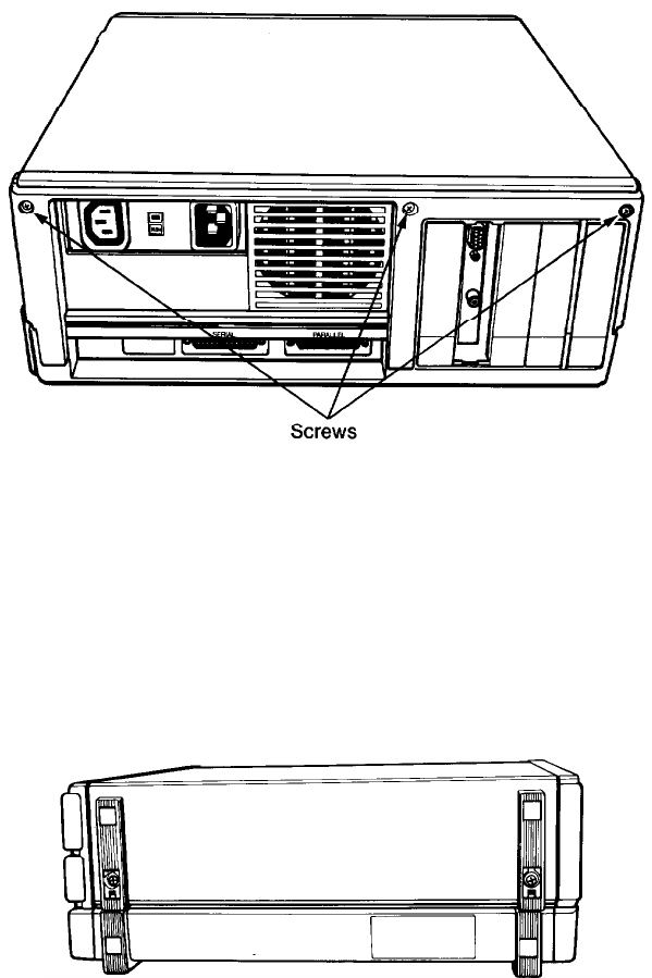
2.
The back panel is secured with three screws as shown in Figure 3-1.
Remove the screws and put them to one side. Slip the back panel off the
main unit.
3.
Figure 3-1. Back panel screws
The top cover is secured by two screws on each side of the computer as
shown in Figure 3-2. The two screws on the left side of the unit are
covered by small plastic inserts. Gently remove the inserts with a small
screwdriver, then remove the screws on both sides of the computer. Put
the screws and inserts safely to one side.
Figure 3-2.
Side screws under plastic inserts
3-2
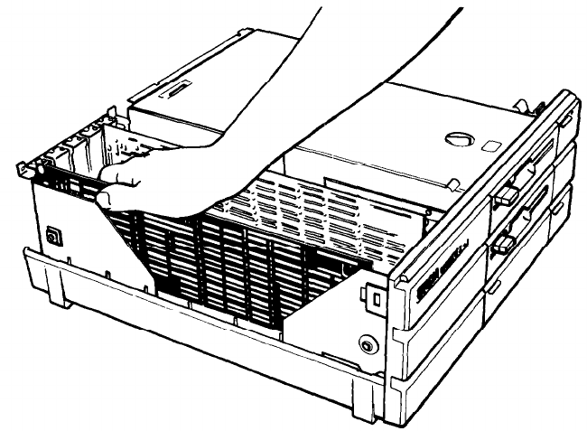
4. Tilt the cover up slightly from the back and pull it toward you and away
from the main unit, as shown in Figure 3-3. Set the cover aside for now.
Figure 3-3. Removing cover
Inserting the Option Card
The video card must be placed in the 4th slot. Figure 3-1 shows the cor-
rect placement of a video card. Most other option cards can be placed into
any of the four remaining option slots, but some cards may need to be in-
stalled in a specific slot. Check the option card manual to find out if the
option card has to be in a specific slot.
Even though option cards are designed to fit only one way, it is a good
idea to examine the card first and follow the instructions closely.
1.
Determine which option slot you are going to use, then remove the
retaining screw and washer from the metal cover plate at the back of the
slot. Lift out the metal cover and put it in a safe place in case you later
remove the option card. Keep the screw and washer to secure the option
card to the computer.
2.
Unpack the option card and read all instructions that come with it.
Then adjust any switches or jumper connections that are necessary.
3-3
Note: Pay specific attention to the warnings in your option card
instructions. Some devices have delicate CMOS chips you
should not touch.
When you handle the card, be careful not to touch any of the contacts
on the circuit board, especially along the gold edge connections. If you
need to put it down before installing it, place it with the component side
facing down on top of the original packing. Keep the card’s original
packing materials in case you remove the card later.
3.
Grip the card firmly by the top corners. The contact pins should be
pointing down and the components should face toward the inside of the
main unit.
4.
Insert the card straight down into the slot as shown in Figure 3-4. Place
the tab at the bottom of the retaining bracket into the corresponding
notch at the back of the computer.
Figure 3-4.
Inserting
option card
5.
Once the connector pins are sitting in the connector slot, push down
firmly (but carefully) to fully insert the card. If the connector does not
seem to be going in smoothly, do not force it; pull it all the way out and
try again. Be sure to keep it straight.
3-4
6. Secure the retaining bracket to the frame of the computer with the small
screw and washer. Also replace the ground screw if there is one. The free
end of long option cards is held in position by a piece of foam inside the
top of the main unit lid and by the card bracket on the inside of the front
panel.
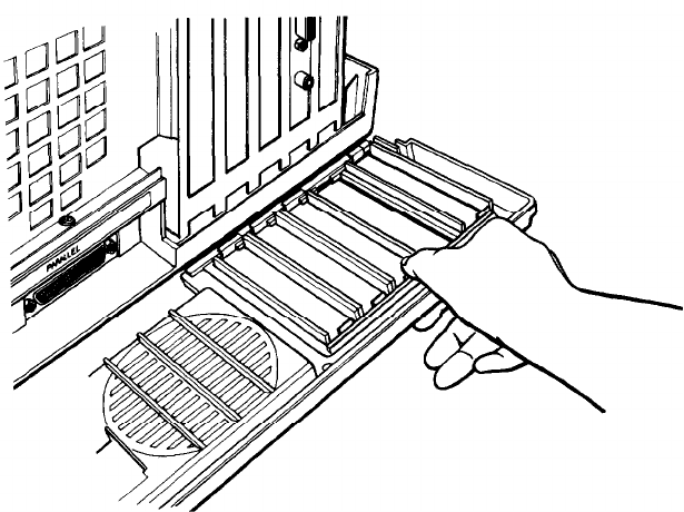
Removing an access slot cover
Some option cards, such as your video monitor card, have an outlet for
connecting an external device. If you install an option card that has an exter-
nal connector for other equipment, (your video monitor, for example), you
need to remove the metal access slot cover on the computer’s back panel that
corresponds to the option card slot. Follow these steps:
1.
Hold the back panel of the computer with the inside facing you. The
individual access slot covers are held in position by a tab at the bottom
and a clip at the top.
2.
Remove the appropriate cover by pushing down on the clip and pushing
out. See Figure 3-5. Save the cover in case you need to remove the
option card.
Figure
3-5. Removing access slot cover
3-5
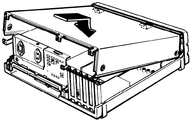
Replacing the Cover
With the option card properly installed or removed, the last step is to
replace the cover of the main unit:
1.
With the back of the main unit facing you, position the cover over the
computer with the side feet to the left of the main unit and the front edge
pointing slightly downward.
2.
Lower the cover onto the bottom half of the case, as shown in Figure
3-6, making sure that the bottom edges fit inside the case. At the same
time, slide the front edge beneath the top edge of the front panel. Finally,
lower the back of the cover so that it is in position.
Figure 3-6. Replacing the cover
3.
Secure the cover by replacing the screws on both sides of the main unit.
Snap the plastic inserts into the side feet.
4. Replace the back panel and the three screws along the top edge.
5.
Return the computer to its original position and reconnect it to the
monitor, the keyboard, and any other peripherals you have.
6. Check to make sure the power switch is off. Reconnect the power cable
to the back of the main unit and to an electrical outlet. Change the DIP
switches if necessary.
3-6
Post-installation Setup
After you install an option card (and replace the main unit’s cover and
reconnect the power cord and peripherals), you may need to change your
DIP switches to update the configuration information. For example, if you
add a floppy disk drive, you need to change switches 1-7 and 1-8 so the
computer knows it has the additional drive.
You may also need to add some commands in the configuration files on
your system disk as well. See your MS-DOS manual for instructions.
When you finish installing an option card and reconfiguring the system,
you should test the option if possible. Some option cards come with their
own diagnostic test programs, and you can test others with your diagnostics
diskette. These tests include:
l Expansion memory
l 8087 math coprocessor
l
Serial and parallel ports
l
Monitors and display adapters
l Disk drives.
See your Diagnostics manual for instructions.
Removing Option Cards
To remove an option card, first turn off the computer and unplug the
power cord, then detach any cable connected to the card. Disconnect the
monitor and keyboard, and remove the main unit cover. Then follow the
option card installation instructions in reverse.
Follow the same safety instructions and make sure you pull the card
straight up and out of the connector to avoid damaging it. Rewrap the card
(preferably with the original packing materials) and place it inside the pack-
ing box for safe storage. Replace the metal access slot cover before you
replace the computer’s cover. If the card you removed had an external con-
nector you also need to replace the plastic access slot cover on the back of the
computer. When you have reassembled the unit, remember to reset any DIP
switches if necessary.
3-7
Chapter 4
Troubleshooting
You should not encounter any serious difficulties with the Equity I+, but
if anything out of the ordinary does happen, this section should help. Such a
situation usually requires nothing more than repeating a software procedure,
correcting an operating system error, or resetting the computer.
Most of the minor difficulties you might encounter can be resolved by
one of the suggestions below. If none of these solves the problem, consult an
Epson dealer about servicing the computer.
WARNING:
If the computer has to be turned off for any reason,
always wait at least five seconds before switching it
back on. Turning it off and on rapidly can damage
the computer.
The Computer Fails to Start Up
If the computer does not start up when you press the power switch on,
follow these steps to find a solution:
1.
Check to see if the power indicator on the main unit is lit. If it is not,
remove any disks and turn the power off. Wait five seconds and turn the
power back on.
2.
If the lamp still does not come on, turn the power switch off. Then check
to see that the power cable is securely connected to the electrical outlet.
Try turning the power switch on again.
3.
If this fails, check the electrical outlet. Plug a portable lamp into the
outlet you are using for the computer, and turn it on to see if it supplies
power.
The Video Display Does Not Appear
If the computer starts up but no image appears on the screen, follow
these steps to find a solution:
1.
Check to see that the power indicator on the monitor is lit. If it is not,
turn the power off, wait five seconds, then turn the power back on. Wait
to see if the display screen appears.
4-1
2.
Use the controls on the monitor to adjust the brightness and contrast.
3.
Check DIP switches 1-5 and 1-6 on the front of the main unit to make
sure they are set correctly for your monitor.
4.
Remove any diskettes, then turn off the monitor and main unit. Check
to see that the monitor power cable is securely connected to the electri-
cal outlet, and that the monitor cable is properly connected to both the
monitor and the main unit. Turn both power switches on again.
5.
With the computer turned off, check the electrical outlet for power. Plug
a portable lamp into the outlet you are using for the monitor, and turn it
on to see if it supplies power.
The Computer Locks Up or Freezes
If the computer appears to be locked up and does not respond to the
keyboard, try the following:
1.
Wait a few seconds. Some operations take longer to perform than oth-
ers. For example, a spreadsheet program takes longer to recalculate an
entire spreadsheet than to simply enter a figure. Also, some BASIC
programs that have a lot of calculations to perform can take several
minutes, or even hours, to finish. Be aware of the task the computer is
performing and judge the time period accordingly.
2.
If the computer remains locked up, follow the steps in Chapter 2 under
“Resetting the Computer.”
Floppy Disk Problems
There are many kinds of disk problems that could occur, and just as
many reasons for them happening. If you are having trouble with your disk-
ettes, check the following questions:
1.
Is your diskette damaged? If you are getting bad results of any type, the
disk could be damaged. Just to be sure, try your backup diskette to see if
the same problem occurs. If the backup works, the first diskette is
probably damaged. Make another working copy from your backup.
2.
Do you have the right type of diskette? In a 360KB drive, use double-
sided, double-density, 48 TN, 360KB diskettes. In a 720KB drive, use
double-sided, high-density, 135 TPI, 720KB diskettes. The diskette type
is normally shown on the manufacturer’s label.
4-2
3.
Is the diskette write-protected? A write-protect tab or switch may be in
place to protect the data on the disk. Think twice before removing the
tab or moving the switch. It might be a new diskette, but it might also be
a diskette with information you do not want to change or lose. Check
the diskette directory to determine what files it contains. The operating
system manual gives the proper directory command. Although you
should normally write-protect program diskettes, there are some pro-
grams which use the program diskette for temporary files, and these do
not work if the diskette has been write-protected.
Hard Disk Problems
If you have problems with your hard disk when you first start to use it,
check to see if it has been set up properly. See “Using a hard disk drive” in
Chapter 2 and refer to your MS-DOS manual.
If you cannot access data stored on your hard disk, you may have acci-
dentally repartitioned or reformatted part or all of the hard disk. If you have
not done so and your hard disk does not function properly, have an autho-
rized Epson service center check your hard disk. Never open the air-tight
container that encloses the recording disk.
Software Problems
If you have trouble with a software program, check the following list of
possible problems and solutions:
1.
The software program does not start. First check that you are following
the right procedure for the operating system you are using. Make sure
that a system disk has been placed in drive A.
2.
An application routine does not work. Refer to the software manual and
complete the routine according to the instructions in the manual. If this
does not work:
l
Start from the beginning by following the reset procedure described in
Chapter 2. Restart the program and try the routine again after the
computer has been reset.
l
Some software programs may need the DIP switches to be set a particular
way to work properly Make sure that the DIP switches are set correctly
for the type of monitor, the amount of memory, and the number of disk
drives you have. The DIP switch settings are listed in Chapter 1. Always
turn off the computer before changing the DIP switches, The new set-
tings are not read by the computer until you turn it back on.
4-3
l
Some programs, for compatibility reasons, may require the computer
to run at 4.77MHz. Try changing the CPU speed with the switch on
the front panel. See “Selecting Execution Speed” in Chapter 2.
Printer Problems
Most of the problems encountered while using a printer can be solved by
checking the manual that came with the printer. If the printer is not working
correctly and has just been installed, first make sure the printer has power
and is correctly connected to the computer. The printer manual provides
instructions on cable connections.
If you have a serial printer, or if you have problems with paper feeding,
you may also need to check the printer manual for the correct DIP switch
settings. The DIP switches on a printer help it communicate properly with
the computer.
Option Card Problems
If you have installed an option card and get unexpected results,
double-check the following points:
1.
2.
3.
4.
5.
6.
7.
Is the option card installed correctly?
Did you follow the setup and operating instructions described in the
option card manual?
Did you set any necessary DIP switches or jumpers on the option card?
See your option card instructions.
Did you set any necessary DIP switches on the main unit? See “Setting
the DIP Switches” in Chapter 1.
Did you change any necessary jumper settings in the main unit? See
Appendix A, “Changing Jumper Settings.”
If you added an external device, did you use the proper cable to connect
the peripheral to the port or option card connector on the rear panel?
Did you perform any necessary post-installation setup procedures for the
operating system? See your Diagnostics, MS-DOS, or other software
manual for instructions.
4-4
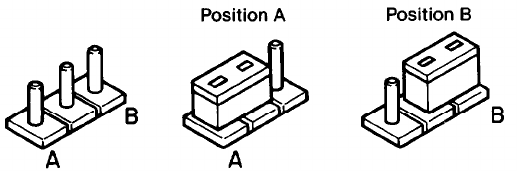
Appendix A
Changing Jumper Settings
This appendix describes how to set the jumpers inside the Equity I+ if
you install optional devices that require different jumper settings than those
set by the factory in the main unit. It is best if your dealer installs the option
and makes all necessary adjustments when you buy it. If you decide to do it
yourself, be very careful when you follow the procedures in this appendix.
There are many system components which can be damaged accidentally.
Jumpers are small electrical connectors that alter some of the computer’s
functions. A jumper’s setting is determined by where the jumper is placed:
either between pin A and the middle pin (position A) or between pin B and
the middle pin (position B). Figure A-1 shows both positions.
Figure A-1. Jumper positions
To move a jumper from one position to another, use needle-nose pliers or
tweezers to lift it off the board and gently move it to the other position. Be
careful not to lose the jumpers or leave them out of the computer.
Jumper J1, Floppy Disk Controller
The built-in floppy disk controller in your Equity I+ can control four
360KB (5%“) or 720KB (3½“) floppy disk drives; therefore, you should not
ordinarily need to install any other type of floppy disk controller. However,
some manufacturers produce combined hard disk and floppy disk controller
cards which you may want to use to control all the drives installed in your
computer. To allow an optional controller to control your floppy disk drives,
you must connect the drives to the option card, and disable the Equity I+
built-in controller.
A-1
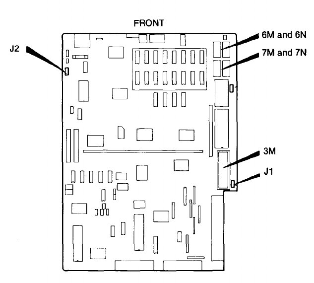
For detailed instructions on how to connect the drives to the optional
floppy disk controller card, consult the documentation supplied with the
card itself. The drive cables for drives A and B are normally connected to
connector CN5 on the system board (shown in Figure A-2). If a different
cable was supplied to connect the drives to the optional controller card,
make a careful note of how the original drive cable was connected, and
remove it from the computer. Keep it in a safe place, in case you need to
remove the optional controller for any reason.
Figure A-2. Jumper locutions
To disable the built-in floppy disk controller, you must first remove the
cover of the main unit (see “Removing the Cover” in Chapter 3). Then
locate Jumper J1 on the main system board, near the option slots, as shown
in Figure A-2. You may need to remove an option card from slot number five
in order to access this jumper. The factory setting is position A. To disable
the internal floppy disk controller, move the jumper to position B. If you
have also installed an additional disk drive, remember to adjust the appropri-
ate DIP switches on the front panel to match the number of drives installed.
A-2
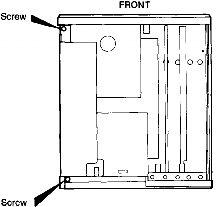
Jumper J2, Parity RAM
Parity RAM enables the computer to make sure that the data stored in
its memory is valid. The Equity I+ can support parity RAM to give you
added protection against loss of data. Installation of parity RAM is a simple
process, but you should ask your dealer to do it for you, as well as test the
RAM carefully. If you decide to install the parity RAM yourself, follow the
instructions below carefully.
You need to install four RAM chips. After you remove the cover of the
computer (see “Removing the Cover” in Chapter 3) locate sockets 6M, 6N,
7M, and 7N. See Figure A-2. Sockets 6M and 7M require 50256 or 51256
type (256KBitxl) h
c
ips; sockets 6N and 7N require 4164 (64KBitxl) chips.
When you insert the chips you must be absolutely certain that each one
is installed correctly, with the notch toward the back of the computer.
Once the chips are installed, locate jumper J2, as shown in Figure A-2.
To reach jumper J2 you need to remove the shielding over the power
supply by removing the two screws shown in the diagram below. Replace the
shielding after you move the jumper.
The factory setting for this jumper is position A. To enable the newly
installed parity RAM, J2 must be moved to position B.
If a fault occurs in the parity RAM, the computer displays a message
during the power-on diagnostics tests. You can continue work by adjusting
Jumper J2 to disable the parity RAM, but other errors may also occur, and
you should report the problem to your Epson dealer as soon as possible.
A-3
Appendix B
Specifications
Main Unit
16-bit CPU
Main memory
Coprocessor
Read Only Memory (ROM)
Direct Memory
Access (DMA)
Interrupt (8259)
Timer/counter (8253-5)
Clock/calendar RAM
Parallel interface
Serial interface
Speaker interface
Option slots
8088 microprocessor; 4.77MHz. or 10MHz
clockrate; switch selectable
640KB
8087 microprocessor (optional)
16KB
Programmable DMA controller with four
channels-two on the mother board (one for
refreshing and one for floppy disk controller),
two available for user peripherals including a
hard disk controller
Programmable interrupt controllers,
8 interrupt levels
Three programmable timer/counters
Real-time clock, calendar, and SO-byte
CMOS RAM for configuration, battery
back-up
Standard 8-bit parallel, DE25 female
connector; programmable
RS-232C, asynchronous, DE25 male
connector; programmable
Internal, controlled by timer/counter
Five IBM-compatible input-output expan-
sion slots
B-1
Keyboard
Layout
Function keys
Detachable, three positions, 101 sculpted keys
58-key QWERTY main keyboard, 17-key
numeric pad, 12 function keys (user-definable)
Three levels (normal/shift/alternate) user-
definable
Mass Storage
Four drives maximum
Standard
5¼-inch, half-height floppy disk drive;
double-sided, doubledensity, 360KB storage
capacity
Optional
3½-inch, half-height floppy disk drive;
double-sided, high density, 720KB storage
capacity
Hard disk drive 3½-inch, half-height internal hard disk drive;
20MB storage capacity (formatted)
Power Supply
Switching type, fan-cooled Output voltage:
-5 VDC, +5 VDC,
- 12 VDC, + 12VDc
Auxiliary AC
Power Requirements: 115/230 VAC
Power Rating: 83W average, 102W peak
Environmental Requirements
Temperature
Operating range: 25° to 90°F (-5° to 35°C)
Nonoperating range: 0° to 149°F
(-40° to 60°C)
Humidity
Operating range: 20% to 80%,
non-condensing
Nonoperating range: 10% to 90%,
non-condensing
B-2
Physical Characteristics (CPU Only)
Width, 14.4” (365mm)
Depth, 14.8” (376mm)
Height, 5.7” (145mm)
Weight, 28.8 lbs. (9kg with one floppy disk drive)
Video and Display Options
Monochrome video
card
Supports Epson or IBM-compatible mono-
chrome monitor; 80-character x 25-line
display; 9 x 14 character block; installs in
option slot
Color/graphics
video card
Supports Epson- or IBM-compatible RGB
color or composite video monitor; 40-
character x 25-line display (low-resolution
text); 80-character x 25-line display (high-
resolution text); 640 x 200 (high-resolution
graphics), 320 x 200 four colors, 160 x 200
eight colors; installs in option slot
Multiple graphics
video card Supports Epson- and IBM-compatible mono-
chrome or color monitor; monochrome text,
color graphics, and Hercules™ (mono-
chrome) graphics, switch-selectable; installs
in option slot
Enhanced graphics
video card Supports Epson- and IBM-compatible mono-
chrome, color; or enhanced color monitor;
monochrome text (80-character x 25-line
display), Hercules text (80-character x 43-line
display); color graphics, 640 x 200 pixels
B/W; monochrome graphics, 640 x 350;
color/graphics, 640 x 350, 16 colors
TTL green or amber High-persistence, P-39 phosphor screen;
monochrome monitor
etched surface to reduce glare; 22 MHz video
(12-inch diagonal)
bandwidth; 35 W
RGB color High-contrast screen; 16 colors; etched
monitor (13-inch surface to reduce glare; I8 MHz video
diagonal)
bandwidth
B-3
Appendix C
Glossary
ASCII
American Standard Code for Information Interchange. A standardized
coding system for representing characters, such as numbers, letters, and
graphic symbols. An ASCII character occupies one byte of storage. Files
transmitted in ASCII code can be used by many different computers,
printers, and programs.
Asynchronous
A method of data transmission in which one machine sends data one
character at a time to another, without either machine preparing for the
transmission.
Backup
An extra copy of a program, data file, or diskette, kept in case your
working copy is damaged or lost.
Bit
A binary digit (0 or 1). The smallest unit of computer storage. The value
of a bit represents the presence (1) or absence (0) of an electric charge.
Boot
To load a program or an operating system.
Byte
A sequence or group of eight bits that represents one character.
Character
Anything that can print in a single space on the page or the screen.
Includes numbers, letters, punctuation marks, and graphic symbols.
CMOS
Complementary Metal-Oxide Semiconductor. A method for making
silicon chips.
Code
A system of symbols for representing data or instructions. Also any soft-
ware program or part of a program.
C-1
Command
An instruction you enter on the keyboard to direct your computer to
perform a specific function.
Configuration
The particular setup of a group of components. For example, a CPU
with two floppy disk drives, connected to a monochrome monitor and a
printer is a typical system configuration.
Control code
A command (generated when, you hold down Ctrl and press another
key on the keyboard) that instructs your computer to perform a specific
function.
CPU
Central Processing Unit. The piece of hardware which interprets
instructions, performs the tasks you indicate, keeps track of stored data,
and controls all input and output operations.
Cursor
The highlighted marker which shows your position on the screen and
moves as you enter and delete data.
Data
Information stored or processed by a computer.
Data diskette
A formatted diskette used to store files.
Diagnostics
The tests and procedures the computer performs to check its internal
circuitry and set up its configuration.
DIP switches
Small switches on a piece of hardware such as a CPU, a printer, or an
option card. DIP switch settings control various functions and provide a
system with information about itself. DIP stands for Dual In-Line
Package.
Directory
A list of the files stored on a disk or a part of a disk.
Disk
The collective term for both hard disks and floppy disks (diskettes).
C-2
Disk drive
The physical device which allows the computer to read from and write
to a disk. A floppy disk drive has a disk slot on the front panel of the
main unit into which you insert diskettes. A hard disk is permanently
fixed inside the main unit, hidden behind the front panel.
Diskette
A flat piece of flexible plastic coated with magnetic material and used to
store data permanently. Also called floppy disk.
DOS
The Disk Operating System that controls the computer’s input and out-
put functions. See Operating system.
Double-density
A type of diskette format that allows you to store twice as much data as
the standarddensity format. A double-density diskette for the Equity I+
has a storage capacity of 360KB.
File
A group of related pieces of information called records, or entries, stored
together on disk. Text files consist of words and sentences. Program files
consist of code and are used by computers to interpret and carry out
instructions.
Floppy disk
See Diskette.
Format
To prepare a new disk (or erase an old one) so it can receive information.
Formatting a disk divides it into tracks and sectors which
create addressable locations on it.
Graphics
Lines, angles, curves, and other nonalphanumeric data.
GW-BASIC
Microsoft’s extended version of the Beginner’s All-purpose Symbolic
Instruction Code. A programming language designed to be easy to use
and understand.
Hard disk
The enclosed unit used to store data permanently. Unlike a floppy disk,
it is fixed in place. It can process data more rapidly and store many more
files than a floppy disk.
C-3
Hardware
Any physical component of a computer system, such as a monitor,
printer, keyboard, or CPU.
Input/output port
See Port.
Interface
A physical or software connection used to transmit data between equip-
ment or programs.
Jumper
A small electrical connector that alters some of the computer’s
functions.
Kilobyte (KB)
A unit used to measure storage space (in a computer’s memory or on a
disk). One kilobyte equals 1024 bytes.
LED
Light Emitting Diode. A substance that illuminates when electricity
passes through it, like the indicator lights on the front panel of the
Equity I+.
Main unit
‘The Equity I+ computer.
Megabyte (MB)
A unit used to measure storage space (in a computer’s memory or on a
disk). One megabyte equals 1,048,576 bytes.
Memory
The area where your computer stores data. Memory contents can be
permanent and inalterable (ROM) or temporary (RAM).
Microprocksor
A small version of a CPU contained on one semiconductor chip.
Modem
A device which allows a computer to transmit signals over telephone
lines so it can send and receive data. Modem stands for MOdulator/
DEModulator.
Monitor
The piece of hardware that contains the screen and displays informa-
tion.
C-4
Monochrome monitor
A monitor that displays in only one color, such as green or amber, as
opposed to a color monitor which can display in several colors.
MS-DOS
An operating system from Microsoft. See DOS, Operating system.
Operating system
A collection of programs that allow a computer to control its operations.
The operating system determines how programs run on the computer
and supervises all input and output-for example, MS-DOS.
Option card
A card you install inside the Equity I+ main unit to provide additional
capabilities, such as more memory or a hard disk drive.
Parallel
The type of interface which transmits data in groups of bits. See Inter-
face, Serial.
Partition
To divide a hard disk drive into separate sections for use by different
operating systems.
Peripheral
A device (such as a printer or a modem) connected to a computer that
depends on the computer for its operation.
Port
A physical input/output socket on a computer where you can connect a
peripheral.
Program
A disk file that contains coded instructions and tells a computer what to
do and how to do it.
RAM
Random Accesss Memory. The part of memory that a computer can
both read and write to. The programs you use are temporarily stored in
RAM. All data stored in RAM is erased when you turn off the power.
C-5
Read
To copy data from one area to another. For example, when you open a
text file stored on disk, the computer reads the data from the disk and
displays it on the screen.
Read/write head
The physical device inside a disk drive that reads and records data on
the magnetic surface of a disk.
Reset
To reload a computer’s operating system so you can retry a task or begin
using a different operating system. Resetting clears RAM.
RGB
Red Green Blue. An RGB monitor displays in high-resolution color.
ROM
Read Only Memory. A portion of memory that can only be read and
cannot be used for temporary storage. ROM retains its contents even
when you turn off the power.
RS-232C
A widely-used, standard type of serial interface. You can easily connect
RS-232C-compatible devices to the Equity I+.
Sector
A contiguous section of a disk track that provides an address at which
the computer can access data.
Self test
The initial diagnostics procedures a system performs to check its
hardware.
Serial
The type of interface which transmits data one bit at a time. See
Interface and Parallel.
Software
The programs that enable your computer to perform the tasks and
functions you indicate.
System diskette
A diskette that contains the operating system.
C-6
Tracks
Addressable concentric circles on a diskette, resembling the grooves on
a record, which help to divide the diskette into separate accessible areas.
There are 40 tracks on each side of a double-sided, double-density disk-
ette and 80 tracks on each side of a double-sided, high-density diskette.
Write
To store data on a disk.
Write-protect
To prevent a diskette from being overwritten by placing a write-protect
tab over the notch on the side of the diskette (5¼-inch) or setting the
write-protect switch (3½-inch). When a diskette is write-protected, you
cannot erase, change, or record over its contents.
C-7
A
Access slot cover, 3-5
AC power inlet, 1-4
AC power outlet, 1-4
Alt, 2-2
Air circulation, 1-2
Application programs, 2-1—2
ARCHIVE utility, 2-10
Arranging components, 1-3
ASCII, 1-12, C-1
Auto-dial modems, 1-5, 3-1
Auxiliary outlet, 1-4
Index
B
Back panel screws, 3-2, 3-7
BACKUP command, 2-10
Backup copies
daily, 2-9
making, 2-9, C-1
Backspace key, 2-2
Bit, C-1
Booting, C-1
Brightness control, monitor, 1-8, 4-2
Button, lock/release, 1-2, 2-7
Byte, C-1
Components, arranging, 1-3
Computer See Equity I+
Configuring, C-1
Contrast control, monitor, 1-8, 4-2
Controllers
Disk, B-1
DMA, B-1
Interrupt, B-1
Printer I/O, B-1
Serial I/O, B-1
Timer/counter, El
Video/Graphic, B-3
Cooling fan, main unit, 1-18
Copying files, 2-9
Cover, main unit, 1-8
CPU, B-1-2, C-2
CPU speed switch, 1-6
Ctrl Alt Del, 2-4
Ctrl key, 2-2
Cursor, C-2
C
Cable
connections, 1-6
keyboard, 1-6, 1-9
parallel, 1-10-12
serial, 1-12
video monitor, 1-7
Caps Lock key, 2-2
Centronics compatible connector,
1-10
Character set, 1-12
Clock/calendar, B-1
CMOS, C-1
Color graphics
connectors, 1-7—8
video card, 1-7—8
Data, C-2
DB-25, 1-10
Del key, 2-2
Diagnostics manual, 1-1, 1-19, 2-7,
2-11, 3-7, 4-4
DIP switch settings, 1-13
DIP switches
built-in interfaces, 1-16—7
coprocessor, 1-15
floppy disk drives, 1-15
functions, 1-6, 1-13, C-2
label, 1-14
keyboard, 1-15
location of, 1-13
memory size, 1-15
monitor type, 1-8, 1-15
parallel port, 1-16-17
RAM size, 1-15
serial port, 1-16-17
D
Index- 1
Diskettes
attaching labels to, 2-6
backing up, 2-4, 2-9
care and handling, 2-4—7
choosing, 2-5
comfortable environment for, 2-6
compatibility with IBM-PC, 2-5
floppy, 2-4, 2-9—10
floppy, blank, 2-7
hard disk; 2-10—11
how they work, 2-5
inserting and removing, 2-4,
2-6-8
magnetic surface of, 2-5
problems, 4-3—4
system, 1-19
type, 2-5
using, 2-4; 2-6
write-protecting, 2-4, 2-8—9
Disk drive
hard, See Hard disk drive
inserting floppy into, 2-6
LED lamps, 1-6
protector sheets, 1-2, 1-18
single floppy, 2-9
slot, 2-9
using, 2-9
DISKCOPY, 2-9
Disk lock/release button, 1-6, 2-7
Display, monitor, See Monitor
DMA, B-1
DOS, C-3
DU, 2-9
E
Electromagnetic interference, 1-3
End key, 2-2
Enter key, 2-2
Environmental conditions, 1-2
Environmental requirements
humidity, B-2
temperature, B-2
Epson printers, 1-10
Equity I+
cable connections, 1-6
components, arranging the, 1-2
disk drive, See
Disk drive
disk, See
Disk
electromagnetic interference, 1-17
environmental conditions, 1-18
front panel, 1-5
main unit, See Main unit
main unit cover, 3-1, 3-7
operating system, 2-9—11
packing materials, 1-1
power cord, 1-6
power switch, 1-18
rear panel, 1-4
resetting the, 2-3
self-diagnostic test, internal, 1-19
special keys, 2-1
turning on power, 1-17
unpacking, 1-1
video monitor, See Monitor
Esc key, 2-2
Execution speed, selecting, 2-2—3
External devices, See Option cards
F
FDISK command, 2-11
Floppy disk
controller, A-1-2
drive, 2-4
problems, 4-2-3
using, 2-9
Format
floppy disk, 2-9
hard disk, 2-11
Formatting, C-3
Front panel, Equity I+, 1-5
G
GW-BASIC, 1-1
Index-2
H
Hard disk drive
care of, 2-9
internal, 2-9
partition, 2-11
problems, 4-3
using, 2-10
Home key, 2-2
HDSIT, 2-7
I
IBM-PC
character set, 1-12, 2-1
diskette format, compatibility, 2-9
Interrupt, 3-1
Initial system testing message, 1-19
Input/output
ports,
1-4, 1-16
Insert key, 2-2
Inserting and removing disks, See
Disk
Interfaces
Clock/calendar RAM, B-1
Option slots, 3-3
Parallel, 1-10
Printer, 1-10
Serial, 1-12
Speaker, B-1
Internal self-diagnostic test, 1-19
J
Jumper settings, changing, A-1 -4,
C-4
K
Keyboard
adjusting the legs, 1-9-10
arranging the, 1-2
cable, 1-8
connecting, 1-8
layout, B-2
socket, 1-6
specifications, B-2
special keys, 2-2
L
Labels, disk, 2-5
LED, power, 2-6
Location, 1-2
M
Magnetic fields, 1-17
Magnetic surface of diskette, 2-5
Main memory, B-1
Main unit, Equity I+
arrangement of, 1-2
cover, removing the, 3-1—3
cover, replacing the, 3-6—7
power switch, 1-17
specifications, B-1
Mass storage capacity, B-2
Memory expansion card, 3-3
connector for, 3-3
installing, 3-1
Modem, C-4
Moderate environment, for disks,
1-2, 2-6
Monitor
arranging, 1-6
brightness and contrast, 1-8, 1-18
cable, 1-6
color, RGB, B-3
connecting the, 1-7
display, B-3
enhanced, B-3
external device connector, 1-6
graphics, B-3
monochrome, C-5
options, B-3
power switch, 1-7
video card, 1-7, B-3
video, 4-1
MS-DOS, 1-1, 1-19, 2-7, 2-9—11,
c-5
N
Num lock key, 2-2
Operating system, C-5
loading an, 1-19
Index-3
O
Option cards
access slot cover, 3-5
connector pins, 3-4
connector slot, 3-4
external device connector, 3-5
installing, 1-13, 3-1—8
long, 3-3
metal cover plate, 3-5
panel, back, 3-1
post-installation setup, 3-7
problems, 4-4
retaining bracket, 3-5
retaining screw, 3-3
removing, 1-18, 3-7
slots, 1-5, B-1
washer, 3-4
Outlet
AC, 1-4
Auxiliary, 1-4
grounded, 1-3
P
Packing materials, 1-1
Page up key, 2-2
Page down key, 2-2
Parallel, C-5
cable, 1-11
interface, 1-11, B-1
printer port, 1-5
Partitioning, C-5
Parity, A-3
Pause key, 2-2
Peripherals, C-5
Physical characteristics, Equity I+
depth, B-2
height, B-2
weight, B-2
width, B-2
Plastic inserts, 3-7
Port, 1-16, C-5
Power
inlet, 1-1
LED lamp, 1-6, 2-6
requirements, B-2
sources, 1-2
supply B-2
switch, 1-6
Power cord, 1-1, 1-6
Power switch, 1-17
Printer
cable, 1-11
character set, 1-12
interface, 1-10-12
parallel, 1-10-12
problems, 4-4
Print screen key, 2-2
Program, C-5
Protector sheets, disk drive, 1-2
R
RAM, A-3, C-5
Read/Write head, C-6
Rear panel, 1-4
Registration cards, 1-1
RESET button, 1-6, 2-4
Resetting the computer, 2-3
Retaining screws, 3-1
ROM, B-1
RS-232C serial port, 1-5, 1-12, C-6
Rules, safety, 1-18
S
Safety, 1-18
Screws
back panel, 3-2
retaining, 3-3
top cover, 3-2
Scroll Lock key, 2-2
SELECT, 2-11
Self-diagnostic test, Equity I+
internal, 1-19
Serial, C-6
cable, 1-12
interface, 1-2, B-1
port, RS-232C, 1-12
Setup, 1-19
Shift key, 2-2
Software, C-6
Software problems, 4-3—4
Special character set, 1-12
Speaker interface, B-1
Special keys, Equity I+, 2-1—2
Speed switch, 2-2 — 3
Squeeze locks, 1-10
Start up failure, 4-1
Index-4
System
arrangement, 1-3
disk, C-6
testing message, 1-19
T
Tab key, 2-2
Timer, B-1
Troubleshooting, 4-1—4
Turning off the computer, 2-4
Turning on the computer, 1-17—19
U
Unpacking the Equity I+, 1-1
Using the Equity I+, 2-1—12
V
Video monitor, See Monitor
W
Write-protect
disks, 2-8—9
notch, 2-8
switch, 2-9
tab, 2-8
tab, removing, 2-8
Writing on labels, 2-4
Index-5

IMPORTANT NOTICE
DISCLAIMER OF WARRANTY
Seiko Epson Corporation makes no representations or warranties, either express or implied, by or with
respect to anything in this manual, and shall not be liable for any implied warranties of merchantability
and fitness for a particular purpose or for any indirect, special or consequential damages. Some
not allow the exclusion of incidential or consequential damages, so this exclusion may not apply to you.
COPYRIGHT NOTICE
All rights reserved. No part of this publication may he reproduced, stored in a retrieval system, or
transmitted, in any form or by any means, electronic, mechanical, photocopying, recording or other-
wise, without the prior written permission of Seiko Epson Corporation. No patent lability is assumed
with respect to the use of information contained herein. While every precaution has been taken in the
preparation of this publication, Seiko Epson Corporation assumes no responsibility for errors or omis-
sions. Nor is any liability assumed for damages resulting from the use of the information contained
herein. Further, this publication and features described herein are subject to change Without notice.
TRADEMARKS
Epson is a registered trademark of Seiko Epson Corporation.
Equity is a trademark of Epson America, Inc
IBM is a registered trademark of International Business Machines Corp.
MS is a trademark of Microsoft Corp.
Copyright © 1986 by Seiko Epson Corporation
Nagano, Japan
ii
Contents
Introduction . . . . . . . . . . . . . . . . . . . . . . . . . . . . . . . . . . .
Intro-1
1
Running the Diagnostics ................
Starting the Diagnostics ....................
The Power-on Self Test
...........................
The OPERATION MENU ...........................
Exiting Diagnostics
................................
Diagnostics and MS-DOS Commands .................
2
Setting Up the System ....................
Using the Setup Program
..........................
Setting the Real-time Clock .....................
Changing Serial Port (RS-232C) Settings..................
3
Formatting a Hard Disk ..........
Formatting and Checking Options
Conditional Format (Normal) ..............
Unconditional Format ........................
Destructive Surface Analysis ..................
Non-destructive Surface Analysis ..........
2-1
2-1
2-3
2-5
1-1
1-1
1-1
1-2
1-2
1-3
.................
3-1
..................
3-1
.....................
3-3
..................
3-5
.....................
3-6
....................
3-8
4Formatting a Diskette..........................
4-1
5
Performing System Diagnostics
............
Using the System Diagnostics Program
..........
Modifying the DEVICE LIST ...............
Selecting a test
............................
Resuming from an error
....................
System Board Check .........................
Memory Check .............................
Keyboard Check ............................
Monochrome Display Adapter and CRT Check ..............
Monochrome adapter check .................
Attribute check ...........................
Character set check ........................
Video check ..............................
Sync check ...............................
Run all above checks .......................
5-1
5-2
5-3
5-4
5-5
5-6
5-6
5-7
5-8
5-9
5-9
5-10
5-10
5-11
5-11
iii
Color Graphics Adapter and CRT Check ...........
Color graphics adapter check
....................
Attribute check ...............................
Character set check ............................
40-column character set check ...................
320x200 graphics mode check
....................
640x200 graphics mode check
....................
Screen paging check
...........................
Light pen check ...............................
Color video check .............................
Synccheck ...................................
Run all above checks ...........................
Floppy Disk Drives and Controller Check ...........
Sequential seek check
..........................
5-11
5-12
5-12
5-13
5-14
5-14
5-15
5-15
5-16
5-17
5-18
5-18
5-18
5-19
Random seek check ..................
Write, read check ....................
Speedcheck ........................
Run all above checks .................
Math Coprocessor Check (8087) .........
Parallel Port (Printer Interface) Check
.....
Parallel Port (on Video Adapter) Check ...
Serial Port (RS-232C) Check ............
Alternate Serial Port Check .............
Dot-matrix Printer Check ...............
Hard Disk Drives and Controller Check
. .
Seek check .........................
Write, read check ....................
Error detection and correction check ....
Read, verify check
...................
Run all above checks .................
.........
5-19
..........
5-19
..........
5-20
..........
5-20
..........
5-21
..........
5-21
..........
5-22
..........
5-22
..........
5-23
..........
5-23
..........
5-24
..........
5-25
..........
5-25
..........
5-26
..........
5-27
..........
5-27
6Moving the Hard Disk . . . . . . . . . . . . . . . . . . . . . . . . .
6-1
7
System-dependent Utilities
....................
7-1
The HELP Utility ..............................
7-1
The ROMBIOS Utility ..........................
7-3
The SYSTAT Utility ............................
7-3
iv
Appendixes
A
Error Codes and Messages . . . . . . . . . . . . . . . . . . . . .
A-1
BPower-on Diagnostics ................
System Device Check ...................
Clock and CMOS RAM Check ..........
RAM Check ..........................
Keyboard Controller and Keyboard Check .
Floppy Disk Drive Seek Check ...........
Tables
. . . . . . .
B-1
. . . . . . . . .
B-1
. . . . . . . . .
B-2
. . . . . . . . .
B-2
. . . . . . . .
B-2
. . . . . . . . .
B-3
A-1 Error codes and messages . . . . . . . . . . . . . . . . . . . . . .
A-1
v
Introduction
This manual describes how to initialize your Epson® EquityTM I+ after
it is assembled, and how to test the condition of your computer and
peripherals. To set up and test your system, you use a set of programs called
diagnostics. The five main diagnostics programs are:
Setup
Use this program when you first set up the
computer,
and any time you change the
system’s permanent date or time or the serial
port configuration.
Format hard disk
Format diskette
Use this program to check or format the
entire hard disk after installation.
Use this program to format a diskette for use
by the System diagnostics tests. This pro-
gram is provided for convenience only, so
that you can format a diskette without exit-
ing diagnostics.
System diagnostics
Use these programs whenever you add or
remove optional devices, or if you suspect
that the system is defective. You also run
these diagnostics after moving the system
from one place to another and after replacing
the internal battery.
Prepare hard disk
Use this program before moving the com-
for moving
puter to another location.
The diagnostics programs are stored on your diagnostics diskette, which
is labelled Diagnostics and System-dependent Utilities for the Equity I+. As
well as the diagnostics, this diskette contains three utilities that are used
exclusively by the Equity I+. These utilities are:
HELP This utility provides information on the
MS’“-DOS commands.
ROMBIOS
This utility displays the computer name and
ROM BIOS version number.
SYSTAT
This utility displays the system parameters.
Intro-1
Chapter 1 describes how to start the diagnostics programs, select options
from the menus, and exit the programs. Chapters 2 through 6 describe each
of the five programs individually, and Chapter 7 describes the three system-
dependent utilities (HELP, ROMBIOS,
and SYSTAT). Appendix A lists the
error codes and messages that may appear during diagnostics checks, and
Appendix B explains the power-on diagnostics messages.
Intro-2
Chapter 1
Running the Diagnostics
This chapter describes how to start and use the diagnostics programs.
Starting the Diagnostics
To start the diagnostics programs, follow these steps:
1.
Turn off the computer and wait for a few seconds.
2.
Place the diagnostics diskette in drive A, and secure the disk drive.
3.
Turn on the computer.
The computer tests itself, and then automatically starts the diagnostics.
The Power-on Self Test
Whenever you turn on or reset the computer, the system performs some
built-in diagnostics called the power-on self test. This test checks the RAM
(random access memory), keyboard, system board, and peripherals before
the computer begins normal operation. For a complete description of the
power-on self test, refer to Appendix B.
If the self test encounters a problem, you see an error message. The error
messages are described in Appendix B.
If the self test finds a discrepancy between the equipment installed on the
computer and the equipment list maintained by the computer, an error
message displays. You can run the SYSTAT program (described in Chapter
7) to see the list of equipment installed and to check the current settings for
your configuration.
1-1
The OPERATION MENU
After the power-on self test completes successfully, the diagnostics start
and you see the OPERATION MENU:
OPERATION MENU
1 - Setup
2- Format hard disk
3 - Format diskette
4 - System diagnostics
5 - Prepare hard disk for moving
0 - Exit to DOS for more utilities
Enter selection number:
You select one of the diagnostics programs by pressing a number from
1 to 5 and pressing Enter. This manual describes each menu item in the
order listed on the OPERATION MENU.
Option 3, Format diskette, is included on the OPERATION MENU for
convenience only. This option lets you format diskettes for use by the System
diagnostics tests without exiting from the diagnostics programs.
To use the extra utility programs on the diagnostics diskette (which do
not appear on this menu), select 0 from the OPERATION MENU. Then
start the utility from the MS-DOS prompt.
Exiting Diagnostics
Option 0 exits the diagnostics programs in one of the following ways:
l
If you have not run a diagnostics program, you see this selection on the
OPERATION MENU:
0 - Exit to DOS for more utilities
In this case, when you press 0 and
Enter,
you see the MS-DOS prompt.
1-2

lIf you have run a diagnostics program, you see this selection on the
OPERATION MENU:
0 - Exit and reset
In this case, when you press 0 and Enter, the system is reset. Before
selecting this option, remove the diagnostics diskette from drive A and
insert your system diskette so the system can hoot normally. If you want to
hoot from your hard disk, make sure no diskette is inserted in drive A.
Diagnostics and MS-DOS Commands
Each choice on the OPERATION MENU corresponds to an MS-DOS
command:
OPERATION MENU Choice
MS-DOS Command
Setup
SETUP
Format hard disk
HDFMTALL
Format diskette
FORMAT
System diagnostics
DIAGSYS
Prepare hard disk for moving
HDSIT
The other MS-DOS commands on the diagnostics diskette are:
SYSTAT
ROMBIOS
HELP
You can copy these MS-DOS commands, with the exception of
DIAGSYS, to your hard disk or to a directory on another floppy disk. You
can then execute the program as an MS-DOS command without loading
the diagnostics diskette. To copy these commands, use the COPY command
described in your MS-DOS manual.
1-3
You can also execute the commands directly from the diagnostics
diskette, without loading diagnostics. For example, if you are logged onto
drive C, and you want to prepare your hard disk for moving, follow these
steps:
1.
Insert the diagnostics diskette into drive A.
2.
At the C) prompt, type:
A: HDSIT
3.
Press
Enter.
To use the System diagnostics program, DIAGSYS, you must always
boot the system with the diagnostics diskette in drive A. If you attempt to
start this program in any other way, the tests may produce strange results.
1-4
Chapter 2
Setting Up the System
This chapter describes how to change the information stored in the
computer’s CMOS RAM. You can select Setup from the OPERATION
MENU, or you can execute the MS-DOS SETUP command.
You must run the Setup program when you turn on your computer for
the first time. You also need to use Setup if you want to:
l
Permanently change the real-time clock’s date or time
lChange the default settings for the serial (RS-232C) port(s).
The information you define with Setup is stored in the CMOS RAM,
which is backed up by a battery. Whenever you turn on the computer, it
searches the CMOS RAM for the correct installation information. If the
computer discovers a difference between the information in CMOS RAM
and the actual configuration, it prompts you to run the Setup program.
Using the Setup Program
To start the Setup program from the diagnostics OPERATION MENU,
press
1
and then press
Enter.
To select the Setup program from the MS-DOS prompt, type SETUP
and press
Enter.
2-1
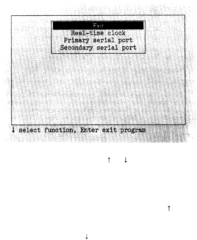
When you start Setup, the main menu is displayed:
Select options from this menu using and to move the cursor block.
When the selection you want is highlighted, press
Enter.
Each option on the main menu (except Exit) displays another menu of
choices. After making your selections on the submenu, you can exit in one
of the following ways:
l
To exit the submenu without making any changes, press until the
cursor block returns to the main menu, or simply press ESC. This
cancels any changes you just made to the configuration.
l
To set your changes, press to highlight
** SAVE SETTINGS
** and
press Enter. When you exit Setup, the changes are written to the
CMOS RAM, and the computer is rebooted with the new settings.
2-2
When you finish using the Setup program, select the Exit option from
the main menu. The program displays a list of the current settings you just
made. Check the list before placing the settings in CMOS RAM. Below the
list you see this menu:
Change settings
Exit without saving
** EXIT AND SAVE **
If any setting is incorrect, press Enter. The main menu is displayed
again, and you can correct the setting.
If you did not make any changes, or if you want to cancel the changes
you made, you can return to the OPERATION MENU or the MS-DOS
prompt without re-booting the computer. Press to highlight
Exit without
saving, and press Enter.
When the settings are correct, press to highlight
** EXIT AND
SAVE **, and press Enter. If you only changed the real-time clock, the
MS-DOS prompt reappears. Otherwise, the program resets the computer
using the new configuration.
If the computer displays a Setup error message during the power-on self
test, run Setup again and check all your settings.
Setting the Real-time Clock
Your computer automatically keeps track of the time and date using a
real-time clock. Because the clock is backed up by a battery, it keeps track of
the time and date even while the computer is turned off.
The MS-DOS TIME and DATE commands, as well as many software
packages, display the time and date held in the clock, but they cannot make
permanent changes to the time and date settings.
Use the Real-time clock option if you need to change the time and date
permanently. For example, you may need to change the clock to accommo-
date seasonal adjustments, such as daylight saving time. Your computer
automatically adjusts for leap years. Note that even though MS-DOS and
your applications programs may use a different format, the real-time clock
uses a 24-hour time format to store the time.
2-3
To set the real-time clock, follow these steps:
1.
On the main menu, press to move the cursor
block
to
Real-time
clock
and press
Enter.
You see the time and date displayed like this:
19:45:55
Time
12-31-1986
Date
2.
To set the time, move the cursor to
Time
and press
Enter. You
see:
hh:mm:ss
Enter the time in the exact form shown in the box, using two digits for
each part; the program automatically inserts the colons (:).
When the time is correct, press
Enter.
If you enter an invalid time, the
computer beeps, and the time does not change.
3.
To set the date, move the cursor to
Date
and press
Enter. You
see:
mm-dd-yyyy
Enter the date in the exact form shown in the box, using two digits for the
month and the day and four digits for the year; the program automatically
inserts the dashes (-).
When the date is correct, press
Enter.
If you enter an invalid date, the
computer beeps, and the date does not change.
4.
When both the time and date are correct, press to return to the main
menu to change other settings.
Note:
The real-time clock settings are updated immediately, not when you
leave Setup.
2-4

Changing Serial Port (RS-232C) Settings
Use the Primary serial port and Secondary serial port options to change
the default parameters for the serial ports installed in your computer. The
primary serial port is the one that you refer to in MS-DOS as COM1:-
normally the built-in serial port. You might use this port for a serial printer,
or an external modem. The secondary serial port is the one you address as
COM2:- normally a serial port on an option card. This might be the name
used for an internal direct modem.
For example, if you have a serial printer attached to the built-in serial
port, you can use the Primary serial port option to match the computer’s
parameters to the printer’s switch settings so that you do not need to use a
MODE command to set up the serial port when it is needed.
The process for changing the default serial port settings is identical for
the primary and secondary serial ports. This section uses the primary serial
port as an example.
To alter the primary serial port parameters, move the cursor to Primary
serial port and press
Enter.
You see a menu of serial parameters similar to
this:
Baud rate 110 bps
Parity None
Data length 8 bits
Stop bits
1 bit(s)
*** SAVE SETTINGS ***
To set the speed of communication, move the cursor to
Baud rate
and
press
Enter.
The screen displays:
110 bps
150
bps
300 bps
600 bps
1200 bps
2400
bps
4800
bps
9600 bps
19200
bps
38400 bps
2-5

Move the cursor to the desired communication speed and press
Enter.
To set the type of parity check, move the cursor to Parity and press
Enter.
The screen displays:
None
Odd
Even
Move the cursor to the correct type of parity check and press
Enter.
To change the data length, move the cursor to
Data length
and press
Enter.
The number changes to either 7 or 8, whichever was not displayed
before. Press
Enter
again if you want to reselect the previous number.
To change the number of stop bits, move the cursor
to Stop bits
and
press
Enter.
The number changes to either 1 or 2, whichever was not dis-
played before. To reselect the previous number, press
Enter
again.
When you finish changing serial port settings, move the cursor to the
Exit
option in the main Setup menu. Then exit the program as described in
the beginning of this chapter.
2-6
Chapter 3
Formatting a Hard Disk
This chapter describes how you check or format a hard disk drive after
installation. After the hard disk is formatted, it can be partitioned and for-
matted for a particular operating system. Formatting destroys all data on the
hard disk, in all partitions, so use this program with extreme care.
Format hard disk is option 2 on the OPERATION MENU. You can
select this option from the OPERATION MENU, or you can execute the
MS-DOS HDFMTALL command.
After you install a hard disk drive, format it using this program, Format
hard disk, and choose option 1, Conditional format (Normal). After format-
ting, you need to partition and format the hard disk for your operating
system(s). Refer to your MS-DOS manual for details on partitioning and
formatting your hard disk for MS-DOS.
You may need to reformat a hard disk later if you have a serious problem
with the drive. However, before completely reformatting the disk, use the
Non-destructive surface analysis test (option 4 on the HARD DISK
FORMAT MENU) to decide if formatting is necessary. If errors occur during
this test, back up your disk, and run the Conditional format followed by
Destructive surface analysis. These tests are described below.
Formatting and Checking Options
When you select option 2, Format hard disk, from the OPERATION
MENU, you see a menu of formatting and checking options:
HARD DISK FORMAT MENU
l -Conditional format (Normal)
3
2 - Unconditional format
- Destructive surface analysis
4 - Non-destructive surface analysis
0 - Exit
Enter selection number:
3-1
The first two options format a hard disk. Normally you use option 1,
Conditional format (Normal). This option automatically locates any bad
tracks that are flagged by the manufacturer and marks them so that they are
never used. Option 2, Unconditional format, requires you to enter the list of
bad tracks.
The other two options test a hard disk for problems. Use option 3,
Destructive surface analysis, to test the entire disk and update the bad track
table. Because this option writes data to the disk as well as reads it, all data
on any track that produces an error is destroyed. To check for unflagged
bad tracks without destroying data, use option 4, Non-destructive surface
analysis.
Many hard disk drives are supplied with a list of bad tracks, but without
the bad tracks flagged on the disk. Other hard disks are supplied with the
bad tracks already flagged. In all cases, run Non-destructive surface analysis
before formatting the disk; this routine finds all bad tracks that are not
flagged.
If the analysis shows that all the tracks listed as bad are already flagged,
you can then use the Conditional format (Normal) option to format the
disk. If the analysis matches the list of bad tracks, but they are not flagged,
run the Destructive surface analysis (to flag the tracks) before formatting the
disk. If the list provided by the drive manufacturer contains bad tracks that
the analysis does not detect, you can use the Unconditional format option to
flag all the bad tracks manually.
When you select an option from the HARD DISK FORMAT MENU,
the program determines the number of hard disk drives installed in your
computer. If you have more than one drive, then each time you select a test
you see this prompt:
Enter drive letter (C/D)?
Press C or
D,
and then press
Enter.
If you have only one hard disk drive, the option you select starts
immediately.
3-2
Conditional Format (Normal)
Use this option to format the hard disk. All flagged tracks are marked so
that they are never used.
To start the Conditional format, press 1 and then Enter.
The program starts to scan the disk to find all tracks flagged as bad,
starting from the innermost cylinder of the disk. During the scan, you see the
number of the cylinder being checked. For example, if you have a 20MB
hard disk, the first messages you see are:
Format Hard Disk
Scanning for flagged bad tracks...
Current cylinder is 614
When the scan is complete, the program displays information about the
condition of the disk. For a 20MB hard disk with no bad tracks, the display
looks like this:
Scanning finished.
Count of tracks flagged bad
=
0
Count of tracks with other errors
=
0
Count of good tracks
= 2460
The program then displays a warning about the consequences of pro-
ceeding with formatting:
WARNING! ALL DATA WILL BE DESTROYED IN ALL
PARTITIONS OF HARD DISK, NOT JUST IN MS-DOS
PARTITION!
Do you want to start formatting (Y/N)?
If there are no tracks with other errors, and you are absolutely sure that
you want to format the hard disk, press Y then
Enter.
The program then asks you once more if you want to continue. You see
this message and prompt:
DOUBLE CHECK THAT YOU HAVE BACKUP DISKETTE
COPIES OF ALL YOUR FILES.
Do you want to exit and check your file copies
(Y/N)?
When you are certain no valuable data will be destroyed, press
N
and
Enter.
3-3
If you cancel formatting at either stage, you see these messages:
Format cancelled.
Press ENTER to return to the menu.
If you continue with formatting, you see:
Now formatting . . .
When formatting is complete, any bad tracks are flagged, and you see a
series of messages like these:
Format finished.
Flagging bad tracks...
Cylinder is xxxx, head is yy
Format completed.
Press ENTER to return to the menu.
Flagged tracks are identified by xxxx and yy. At this point, press
Enter
to
return to the HARD DISK FORMAT MENU.
If there are any tracks with other errors, scanning stops and you see the
message:
Scanning cancelled.
Warning: This drive has an unflagged error(s),
or is unformatted.
Press ENTER to return to the menu.
Press
Enter.
This may mean that the drive has never been formatted or that an error
was not flagged. If you see this message, it is best to consult your dealer.
If you want to format the disk after receiving this error message, do the
following:
1.
If the drive is not formatted, run the Unconditional format (option 2)
and enter any tracks you know are bad in the Bad Track Table. (See
“Unconditional Format” below.)
2.
Run the Destructive surface analysis (option 3) to flag any remaining bad
tracks. (See “Destructive Surface Analysis,” below.)
3.
Run the Conditional format again. No errors should occur; if one does,
contact your dealer.
3-4

Unconditional Format
Use this option to format your hard disk when you want to enter the list
of bad tracks before formatting begins. The main difference between uncon-
ditional and conditional formatting is the way in which bad tracks are identi-
fied. With the unconditional format, you must enter the list of bad tracks
before formatting begins.
To start the Unconditional format routine, press 2 and then Enter.
You are first given the option to change the interleave factor for format-
ting from the default value of three. Only do this if the documentation with
your hard disk recommends a different value. You see this prompt:
Do you want default interleave of
3
(Y/N)?
To accept the default, press Y and
Enter.
To change the value, press
N
and
Enter.
You see this prompt:
Enter interleave factor
(1-16):
Type the recommended value, and press
Enter.
The next screen allows you to enter the list of bad tracks. The empty bad
track table looks like this:
Bad Track Table
Cylinder Head Cylinder Head Cylinder Head Cylinder Head Cylinder Head
Move highlighted area to desired track with cursor keys.
A = Add track, F = Finish editing
Enter command letter:
3-5
To add a bad track, follow these steps:
1.
2.
3.
Press
A.
You see this prompt:
Enter cylinder number (1 - xxxx):
Type the number of the cylinder containing the missing bad track, and
press
Enter. You
see this prompt:
Enter head number (0 - yy):
Type the head number for the bad track, and press Enter. The maxi-
mum valid cylinder and head numbers (
XXXX
and yy) vary according to
the type of the hard disk.
To cancel this operation, press
Enter
without entering a value. You see
this message:
Table unchanged.
If you enter an invalid cylinder or head number, a reminder of the range
of values is displayed, and the program asks you to enter the value again.
When you complete a valid entry, it appears in the table, and you can select
another command.
If you make a mistake, move the cursor block to the incorrect track, and
press C to alter the track data. Or you can press
D
to remove the track from
the table. Change the track data just like you add a track.
When you have finished editing,check the entries in the table once
more. When you are sure the table is correct, press F.
The program displays a warning about the consequences of proceeding
with formatting, and the remaining steps are exactly the same as for a normal
conditional format.
Destructive Surface Analysis
Use this option to accurately locate any bad tracks on a hard disk, and
to flag any bad tracks that are not flagged.
WARNING: If any errors occur during this check, all data on the track
that produces the error is destroyed. For this reason, if
you think that an unflagged bad track is causing trouble,
first run option 4, Non-destructive surface analysis, to
check the disk surface.
3-6
This test operates by a complex process of writing, reading, and
verifying
information on every track of the hard disk, except for tracks that are
already flagged as bad tracks.
To start the test, press
3
and
then
Enter. You
see these messages:
Analyze Hard Disk
Read/Save/Write/Read/Restore/Read check for all
tracks...
Current cylinder is xxxx
As each track is checked, the
cylinder number (xxxx) counts down to zero.
When the analysis is complete, the program displays a complete report on
the status of the disk, including a table of unflagged tracks that produced
write, read errors. For a 20MB hard disk with one flagged bad track, you see
this display:
Analysis finished.
Count of tracks flagged bad
=
1
Count of tracks with write, read errors
=
0
Count of good tracks
= 2459
No write, read error was detected.
No data was destroyed.
Press ENTER to return to the menu.
If the program finds one bad track that is not flagged, the summary
above shows one track with a write, read error, and only 2458 good tracks.
The report is then followed by a table like this:
Write, Read Error Tracks
====================
Cylinder Head Cylinder Head Cylinder Head Cylinder Head
237 2
Confirm to register the tracks in the Write, Read Error
Track Table as bad tracks.
Do you want to register the error tracks as bad tracks (Y/N)?
3-7
To flag the error tracks as bad, press
Y
and
Enter.
You then see a list of
the tracks as they are flagged. You see these messages:
Flagging bad tracks...
Cylinder is 237, head is 2
Press ENTER to return to the menu.
Press Enter to return to the HARD DISK FORMAT MENU.
Non-destructive Surface Analysis
The Non-destructive surface analysis is slightly simpler than the
Destructive surface analysis described in the previous section. This option
does not destroy any data, and can safely be used to check the condition of
your hard disk drives. However, this test will not flag any bad tracks that are
detected.
To start the test, press 4 and then
Enter. You
see these messages:
Analyze Hard Disk
Read/Verify check for all tracks...
Current cylinder is xxxx
As each track is checked, the current cylinder is displayed. The cylinder
number counts down to zero as the disk is checked.
When the analysis is complete, the program displays a summary of the
status of the disk. This summary lists these counts:
l Flagged bad tracks
l
Tracks with read, verify errors
l Good tracks.
If no errors occur, you see this message:
No read, verify error was detected.
If errors are found, the program displays a table of the tracks that gave
errors, similar to the one displayed by the destructive analysis.
After the status reports you see this message:
Press ENTER to return to the menu.
Check the information displayed, then press
Enter.
3-8
Chapter 4
Formatting a Diskette
This chapter briefly describes how to format a diskette with diagnostics.
Normally, you format a diskette using the MS-DOS FORMAT command.
However, if you are running diagnostics and decide to test your floppy drives
(which requires a formatted diskette), you can select option 3, Format disk-
ette, from the OPERATION MENU. This option lets you format a 360KB
double-density or a 720KB high-density diskette without exiting diagnostics.
The Format diskette program destroys any data on the diskette. When
formatting your diskettes, the program also initializes the directory and file
allocation tables.
To format a diskette, select option 3 from the OPERATION MENU. If
you have two diskette drives, you see this message and prompt:
Format Diskette
Format in which drive (A/B)?
Press
A
or
B
and
Enter.
Then this prompt displays:
Insert new diskette for drive A:
and strike ENTER when ready
(The A : is B : if you selected that drive.) Insert the diskette to be formatted
and press
Enter.
The screen displays the head and cylinder numbers as the
diskette is formatted.
When the format is complete, you see these messages (for a 360KB
diskette):
Format complete
362496
bytes total disk space
362496
bytes available on disk
Format another (Y/N)?
You can format another diskette or return to the OPERATION MENU.
For a complete description of the FORMAT command, refer to the
MS-DOS manual.
4-1
Chapter 5
Performing System Diagnostics
This chapter describes how to check the operation of the main unit and
peripheral devices of your Equity I+. You check these devices using System
diagnostics, option 4 on the OPERATION MENU.
Always run diagnostics after adding or removing optional devices, or if
you are unsure whether a device is performing correctly. You should also run
these tests after moving your computer from one place to another, and after
you replace the internal battery
Note: To run System diagnostics, boot your system with the diagnostics
diskette in drive A. Then select option 4 from the OPERATION
MENU. If you start this program in any other way, some tests may
produce strange results.
You can test the following 13 devices; each has a specific reference
number:
1 - System
2 - Memory
3 - Keyboard
4 - Monochrome display adapter and CRT
5 - Color graphics adapter and CRT
6 - Floppy disk drives and controller
7 - Math coprocessor (8087)
9 - Parallel port (printer interface)
11 - Serial port (RS-232C port)
12 - Alternate serial port
14 - Dot-matrix printer
17 - Hard disk drives and controller
81 - Parallel port on video adapter
Appendix A lists the possible errors you may see when testing these
devices.
5-1
Using the System Diagnostics Program
When you Start the System diagnostics, the computer checks:
lThe setting of the DIP switches on the front panel
l
The positions of the internal jumpers
l
The peripheral devices that are connected to the system.
After these items are checked, you see a list of the devices available for
testing. This list includes only the devices that are installed in the system,
and looks something like this:
The following devices have been installed
DEVICE LIST
1 - System board
2 - Memory
3 - Keyboard
4 - Monochrome display adapter and CRT
6 - Floppy disk drives and controller
9 - Parallel port (printer interface)
11 - Serial port (RS-232C port)
14 - Dot-matrix printer
17 - Hard disk drives and controller
Is the DEVICE LIST correct (Y/N)?
If the list correctly describes your system, press Y and then
Enter.
If a device
is missing from this list, or if you wish to change the list, press N and
Enter.
Then follow the instructions below to modify the device list.
Note: Once you confirm the DEVICE LIST,
you can only test those items.
If you decide later that you need to add another device, you must
first return to the OPERATION MENU and re-select System
diagnostics.
5-2
Modifying the DEVICE LIST
If an installed device is missing from the DEVICE LIST, it is important
that you add it to the list and test it carefully. In response to this prompt:
Is the DEVICE LIST correct (Y/N)?
press N followed
by Enter. You see a
new menu:
Modify DEVICE LIST
l -Add devices
2 - Delete devices
0 - Exit
Enter selection number:
To add a device to the list, press
1
and then
Enter.
The program displays a list of other devices that are not currently
included in the DEVICE LIST.You see a menu similar to this:
Additional DEVICE LIST
5 -Color graphics display adapter and CRT
7 - Math coprocessor (8087)
12 - Alternate serial port
81 - Parallel port {on video adapter)
0 - Exit
Enter the number of the item to add:
5-3
Type the number of the item you wish to add and press
Enter. That
item
disappears from the Additional DEVICE LIST on the screen.
You can add as many devices as necessary. When you finish adding
devices, press
0 and Enter
to return to the Modify DEVICE LIST menu.
Note:
Even if you have both monochrome and color monitor video cards
installed, you can only test the monitor that is currently selected by
DIP switches 1-5 and 1-6 on the front panel.
To remove a device from the list, press
2 and Enter.
The screen displays
the current DEVICE LIST and the prompt:
Enter the number of the item to delete:
Type the number of the item you wish to delete and press
Enter.
That item
disappears from the DEVICE LIST on the screen. You can delete as many
devices as necessary. When you finish deleting items, press
0
and
Enter
to
return to the Modify DEVICE LIST menu.
When you finish modifying the DEVICE LIST, press 0 and then
Enter.
The screen displays the modified DEVICE LIST for a final check. If the list is
correct, press
Y
and
Enter.
You are now ready to select a test.
Selecting a test
From the DEVICE LIST, select the device to be tested. Type the num-
ber of the device, then press
Enter.
Before the test begins, you are asked how many times to perform the
test. You see this menu:
Number of times to test device
l -Run test o
ne time
2
- Run test multi
ple times
0 - Exit
Enter selection number:
5-4
You can specify that the test be performed one time only or any number
of times in the range from 1 to 9999. Running a test multiple times is for
reliability testing of essential functions only; in most cases, running a test
only once is sufficient.
To perform the test
once
only, press
1
then
Enter.
The program displays
a submenu of more detailed tests for the device you are checking.
To perform the test multiple times, press 2 and Enter. You see this
prompt:
Terminate checking if an error detected (Y/N)?
Press
Y
and
Enter
to terminate checking if the device produces an error, or
press
N and Enter
to repeat the tests regardless of an error.
Y
OU
see this prompt:
How many times (1-9999) :
Type the number of times you wish to repeat the test, then press
Enter.
The
tests for the device now start.
Resuming from an error
If an error occurs during a test, the test stops at that point, and an error
code and error message are displayed. If you want to record the problem,
you can print out the message on your printer. You see this prompt:
Do you want a printout of the error message(s)
(Y/N)?
To continue without printing the error
message,
press
N and Enter.
Before you request a printout, be sure your printer is turned on and
on-line, and the paper is installed correctly. Then press
Y
and
Enter.
If the
printer is not ready, the following message and prompt arc displayed:
Printer is not installed correctly.
Install correctly and enter Y, or
Enter N to cancel printing.
Correct the the problem
and
press
Y and Enter
to, continue printing, or press
N
and Enter
to cancel printing.
After printing the error message, the program displays this prompt:
Printout is finished. Press ENTER to return to
the menu.
5-5
The program continues after an error in one of the following ways:
l
It returns to the DEVICE LIST, or
l
If you are running multiple tests and are not terminating on an error, the
program repeats the test that caused the error.
The remainder of this chapter describes the tests you can run on the
system’s internal devices and on the optional devices installed in your com-
puter. The program displays the title of each check on the screen.
For a complete list of the error codes and messages that are displayed by
these tests, refer to Appendix A.
System Board Check
Use this option to check the operation of each major component on the
system board, including:
l
The 8088 CPU chip
l The system ROM
l
The real-time clock, CMOS RAM, and battery
l
The main integrated circuits.
The checks made on the 8088 CPU chip are extremely comprehensive.
They ensure that the CPU instruction set is functioning correctly.
If an error is reported, write down the error code and message, or print
them out, and contact your Epson dealer. Attempting to correct
system board errors yourself may violate your warranty agreement.
Memory Check
Use this option to check the computer’s built-in memory. The program
checks the DIP switches to determine the amount of main memory. If any
settings are incorrect, check the DIP switches to make sure they match the
installed memory.
Note: This option does not check expanded memory above the 640KB
memory limit imposed by MS-DOS.
5-6
For this check, the program writes specific data into memory and then
reads it back. The data is written and read in blocks of 64KB. A parity check
is also made on each block. A count of memory is displayed after each block
that is tested without an error. The final message is usually:
640 KB
OK
If an error is reported, write down the error code and message, or print
them out, and contact your Epson dealer. Attempting to correct memory
errors yourself may violate your warranty agreement.
Keyboard Check
Use this option to check the operation of the keyboard. The program
first checks the keyboard controller; during this check, you see the green
indicator lights on the keyboard flash. If no errors are detected, you can then
choose the correct keyboard layout.
Before checking the operation of the keys, you must select the appro-
priate keyboard layout so that the test display matches the keys on your
keyboard. You see this menu:
KEYBOARD SELECT MENU
l -US ASCII
3
2 - United Kingdom
- French
4
- German
5 - Italian
6 - Spanish
0 - Exit
Enter selection number:
Type the number of your keyboard layout, then press
Enter. You can
exit
the keyboard test by pressing 8 and
Enter.
After you select a keyboard layout, the program displays the layout on
the screen. Press each key on the keyboard to make sure the corresponding
character is displayed on the screen. If the character displayed on the screen
does not match the key you pressed, there is a problem with your keyboard.
Test each key.
5-7
The status of the Num Lock, Caps Lock, and Scroll Lock indicators is
shown on the upper right side of the keyboard layout.
These messages appear on the screen:
KEYBOARD CHECK
Press Y followed by ENTER to exit.
Press N followed by ENTER if screen and keyboard
do not match.
If al1 the keys function correctly and match the characters displayed, press Y
and then
Enter.
If a11 the keys function, but the characters displayed do not match the
keys,
press
Y and
then
Enter.
Then reselect the keyboard test from the
DEVICE LIST, and check that you selected the correct keyboard layout.
You can find diagrams of all the international keyboard layouts in the
MS-DOS manual.
If
any key is incorrect, press
N
and
Enter.
Make a copy of the error code
and message, or print them out
, and contact your Epson dealer.
Monochrome Display Adapter and CRT Check
Use this option to check the operation of a monochrome display adapter
and monitor. This test includes several checks that allow you to identify
particular problems related to the monochrome display. To run this check,
DIP switches 1 - 5 and 1-6 on the front panel must be set correctly for a
monochrome monitor.
You can select the individual checks from this menu:
MONOCHROME ADAPTER AND CRT CHECK MENU
1
- Monochrome adapter check
3
2 - Attribute check
- Character set check
4 - Video check
5 - Sync check
6 - Run all above checks
0 -
Exit
Enter selection number:
5-8
If you specified to run the monochrome check multiple times,
this menu of checks does not display and only the first test (option 1) is
performed.
If an error occurs during any of these tests, record the error code and
message, or print them out. Then contact your Epson dealer.
When you finish running the monochrome adapter check, press 0 and
Enter to return to the DEVICE LIST.
Monochrome adapter check
To
check the monochrome adapter, press
1
and then
Enter.
The computer checks the video RAM display
memory) on the display
adapter by writing certain data to memory, then reading it back and compar-
ing it to the written data. The video enable signal of the display controller
chip is also tested.
Attribute check
To check the display attributes of the adapter card, press 2 and then
Enter.
A series of messages are displayed showing examples of all the possible
display attributes (normal intensity high intensity, blinking, reversed charac-
ters, and underlining). Check the information displayed on your screen, and
then respond to the prompt:
Is
the display correct (Y/N)?
Press
Y
and then
Enter
if the display is correct.
If the display attributes are not correct, adjust the brightness and
contrast on your display monitor. If they are still incorrect, press N and
Enter.
Contact your Epson dealer to make sure that your monitor is able to
display all the attributes available, and to ensure that your monitor cable is
not damaged.
5-9
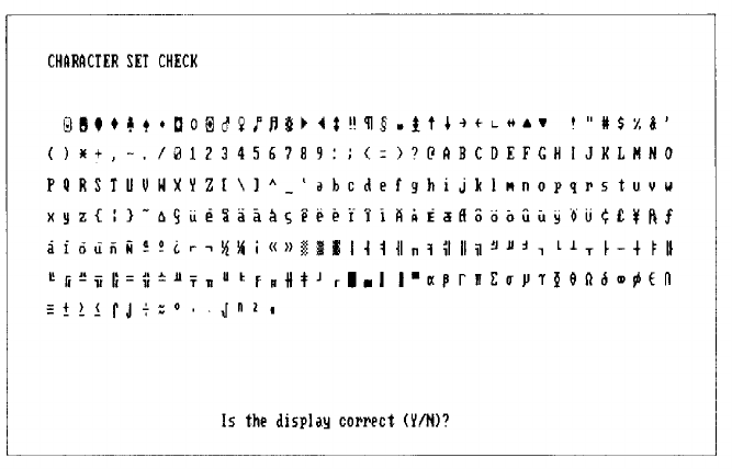
Character set check
To check your character set, press 3 and then Enter. The character
fonts that are included in the internal character generator are displayed.
Check the characters displayed on your screen against this illustration:
After checking the character fonts, respond to the prompt:
Is the display correct (Y/N)?
If the characters displayed match the illustration, press Y and
Enter.
If you
find a problem with the characters on the screen, press N and then
Enter
to
display the error message.
Video check
To check the video output of your monochrome adapter, press 4
followed
by Enter.
This check displays two different screens, black and intensified white.
First you see the black screen; press any key to display the intensified white
screen. Then press any key to end this check.
You can use this display to adjust the size of the display on the screen.
The vertical and horizontal adjustments are located on your monitor.
5-10
Sync check
This test is provided for service purposes only. If you accidentally select
this option, press any key to end the test.
Run all above checks
To run all the tests on the menu in
sequence,
press
6 and Enter.
When you choose this option, all checks for the monochrome adapter
and CRT are performed automatically in sequential order. Although you do
not start each test, you must still supply the appropriate responses to progress
from one test to the nest.
Color Graphics Adapter and CRT Check
Use this option to check the operation of a color graphics display
adapter and monitor. This test includes several checks that allow you to
identify particular problems related to the color display. To run this check,
DIP switches 1 - 5 and 1 - 6 must be set correctly for a color monitor.
You can select the individual checks from this menu:
COLOR GRAPHICS ADAPTER AND CRT CHECK MENU
1- Color graphics adapter check
3
2 - Attribute check
- Character set check
4 - 40-column character set check
5 - 320X200 graphics mode check
6 - 640X200 graphics mode check
7
- Screen paging cheek
8
- Light pen check
9 - Color video check
10 -
Sync check
11 - Run all above checks
0 - Exit
* Enter selection number:
If you specified to run the color adapter check multiple times, this menu
does not display and only the first test (Color graphics adapter check) is
performed.
5-11
If an error occurs during any of these tests, record the error code and
message, or print them out. Then contact your Epson dealer.
When you finish running the color adapter check, press
0 and Enter
to
return to the DEVICE LIST.
Color graphics adapter check
To check the color graphics adapter, press
1 and
then
Enter.
The computer checks the video RAM (display memory) on the display
adapter by writing test data to memory, and then reading it hack and com-
paring it to the written data. The video enable signal of the display controller
chip is also tested.
Attribute check
To check the display attributes of the color graphics adapter card, press
2 and Enter.
Several messages and displayed showing examples of all the possible
display attributes and colors. Check the information displayed on your
screen, and respond to the prompt:
Is the display correct (Y/N)?
Press
Y
and then
Enter
if the display is correct.
If the colors are not correct, adjust the controls on your display monitor.
If they are still incorrect, press
N and Enter.
Contact your Epson dealer to verify any monitor problems.
5-12
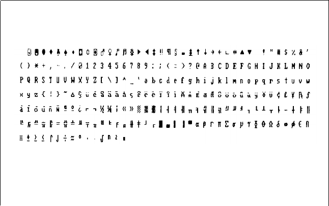
Character set check
To check your 80-column character set, press 3 and Enter. The charac-
ter fonts that are included in the internal character generator are displayed.
Check the characters displayed on your screen against this illustration:
CHARACTER SET CHECK
Is the disp1ay correct (Y/N)?
After checking the character fonts, respond to the prompt:
Is the display correct (Y/N)?
If the characters displayed match the illustration, press Y and then
Enter. If
you find a problem with
the characters on the screen, press N and
Enter to
display the error message.
5-13
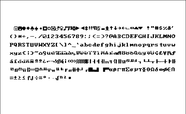
40-column character set check
To check your 40-column character set, press 4 and then Enter. The
character fonts that are included in the internal character generator are
displayed. Check the characters displayed on your screen against this illus-
tration:
40-COLUMN CHARACTER SET CHECK
Is the display correct (Y/N)?
After checking the character fonts, respond to the prompt:
Is the display correct (Y/N)?
If the characters displayed match the illustration, press
Y and Enter.
If you
find a problem with the characters on the screen, press N and Enter to
display the error message.
320x200 graphics mode check
To
check your 320x200 graphics mode, press
5
and then
Enter.
The screen displays three colored squares-light green, brown, and
red--against a cyan background. These four colors are Color Set 0. If they
are correct, press Y and then
Enter.
The same pattern is displayed again; this time the squares are cyan,
white, and magenta, and the background is red. These colors are called
Color Set 1. If these are also correct, press Y and then Enter to end the test.
5-14
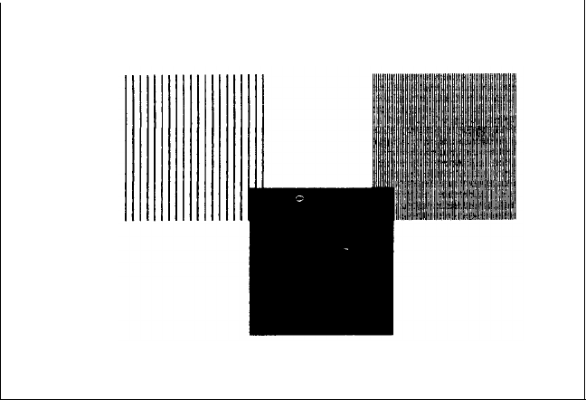
If any colors are displayed incorrectly, first check the adjustment of your
monitor, and make sure that both ends of the cable are plugged in firmly. If a
problem still exists, press
N
and
Enter
to display the error message.
640x200 graphics mode check
To
check your
640x200
graphics mode, press
6 and Enter.
The screen displays three patterned squares against a black background,
as shown below.
640X200 GRAPHICS
MODE
CHECK
Is the display correct
(Y/N)?
If the patterns on your screen are clear and distinct, press Y and then
Enter.
If any pattern is not displayed clearly, first check the adjustment of your
monitor, and then make sure that both ends of the cable are plugged in
firmly. If a problem still exists, press N and Enter to display the error
message.
5-15
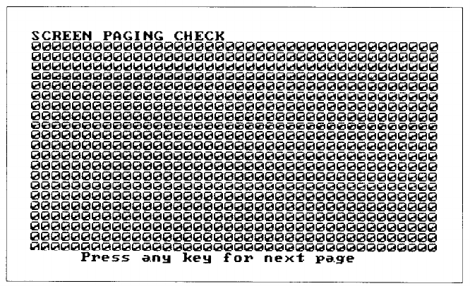
Screen paging check
To check the screen paging of your monitor, press 7 and
Enter.
The video RAM on the color graphics adapter is divided into eight
independent display pages. This test checks the eight pages by first filling all
eight with a number corresponding to the page, and then displaying each
page in turn. You see this pattern for screen 0:
When you have examined this screen, press any key to display the next page.
The eight display pages, numbered 0 to 7
, are displayed sequentially.
After the eighth page is displayed, you see the prompt:
Is the display correct (Y/N)?
If all eight pages are correct, press
Y
and
Enter.
If any page is filled with an
incorrect number, press
N and Enter
to display the error message.
Light pen check
To check the function of a light pen connected to the color graphics
adapter card, press
8 and
then
Enter.
This test checks that a light pen connected to the color graphics adapter
is performing accurately. When you select this check, you see these prompts:
Enter Y to start light pen check.
Enter N to return to the menu.
5-16
If you do not have a light pen attached, press
N
and
Enter. To
begin the test,
press
Y
and
Enter.
You see this prompt:
PLACE LIGHT PEN ON CENTER OF WHITE
BLOCK
Touch the center of the white block on the screen with the light pen.
When the light pen is correctly positioned, the block mows to another part
of the screen for a second test. After three successful tests, the check ends.
An error occurs if:
l
The light pen is not connected properly
l
You touch the screen at the wrong point
l
The light pen is malfunctioning
l
You do not touch the square within a certain amount of time (depen-
dent on the current CPU speed).
Color video check
Option 9, Color video check, displays 16 different screens, each a differ-
ent color, and a message indicating the color. The screens show the following
colors in the order specified below:
1 - Black
2 - Blue
3 - Green
4 - Cyan
5 - Red
6 - Magenta
7 - Brown
8 - White
9 - Gray
10 - Light blue
11 - Light green
12 - Light cyan
13 - Light red
14 - Light magenta
15 - Yellow
16 - White (high intensity)
To start this test, select option 9 from the menu; the first screen is
displayed. Press any key to display the next screen. On the last screen, you
see this prompt:
Is the display correct (Y/N)?
If all the colors arc correct, press Y and Enter to end the test. If any color is
displayed incorrectly, first
check
the adjustment of your monitor, and then
make sure that both ends of the cable are plugged in firmly. If a problem still
exists, press
N and Enter
to display the error message.
5-17
Sync check
This test is provided for service purposes only. If you accidentally select
this option, press any key to end the test.
Run all above checks
To run all the tests on the menu in sequence, press
11
and
Enter.
When you choose this option, all checks for the color adapter and CRT
are performed automatically in sequential order. Although you do not start
each test, you must still supply the appropriate responses to progress from
one test to the next.
Floppy Disk Drives and Controller Check
Use this option to test the performance of the floppy disk drives installed
in your computer. This test includes several checks that allow you to identify
particular problems related to your floppy disk drives.
Before running these tests, format a floppy disk to use for the tests that
write data on the disk in the drive. In a 360KB drive, you can only use a
360KB floppy disk. In a 720KB drive, use only a 720KB diskette.
You can select the individual tests from this menu:
FLOPPY DISK DRIVE(S) AND CONTROLLER CHECK MENU
1- Sequential seek check
2
- Random seek check
3 - Write, read check
4 - Speed check
5 - Run all above checks
0 - Exit
Enter selection number:
Before any checks are performed, the program determines the number
of floppy disk drives installed in your computer. If you have more than one
drive, you see this prompt each time you select a test:
Check which drive (A/B)?
5-18
Press
A
or
B
and then
Enter.
If any errors occur, record the error code and message and contact your
Epson dealer. Always have the floppy disk drive serviced by your Epson
dealer.
Sequential seek check
This test checks the ability of the read/write heads to locate any part of
the diskette. This action by a read/write head is called a seek. During this
test, each head seeks sequentially from the innermost track to the outermost
track. The innermost track is track 39 for 360KB diskettes and track 79 for
720KB diskettes.
Select option 1 from the menu to start this test.
The program displays the number of each track it finds. For example,
with a 360KB floppy disk, the first message you see is:
Current track is
39
The track number counts down (from 39 or 79) to 0.
The seek is performed by each head, so you see the count twice. If no
errors occur, the menu is displayed.
Random seek check
This test ix identical to the sequential seek check, except that the seek
operation is performed on each track in random order instead of sequential
order.
Select option 2 from the menu to start this test.
Write, read check
This test checks the ability of the selected disk drive to read and write
data from a diskette. The test writes to and reads from each cylinder on the
diskette, starting at the center.
Note: This test destroys all data on the diskette in the selected drive.
Select option 3 from the menu to start this test.
5-19
If you have only one floppy disk drive, you are prompted to change the
diagnostics diskette for a blank diskette before running the test. You see these
messages:
Use only a formatted blank diskette for this
test.
Any data present may be erased.
If using drive A, remove your Diagnostics Disk.
Enter Y to start this check.
Enter N to return to the menu.
Make sure the blank diskette you prepared is in drive A, then press
Y
and
Enter.
The program displays the current track number as each cylinder is
tested. For example, with a 720KB floppy disk, the first message you see is:
Current track is
79
Speedcheck
This test checks the revolution speed of the specified disk drive. Select
option 4 from the menu to start this test. You see a message similar to this:
The disk rotation speed should be more than
294.0 rpm and less than
306.0
rpm.
The computer spins the diskette for a few seconds then displays a
message like this:
The disk rotation speed is now
300.0
rpm.
Note:
The speed for a 360KB or 720KB (3½-inch) drive should be 300 rpm.
This check permits a tolerance of ± 2%.
The diskette continues to spin,
and the disp1ay is updated every few
seconds. To stop the test, press any key; the program returns to the menu.
If you try to perform a speed test without inserting a floppy disk, or if a
read error occurs, you see this message and prompt:
Disk is defective or not installed properly.
Press ENTER to return to the menu.
Run all above checks
To
run all the tests on the
menu
in
sequence,
press
5 and
then
Enter.
5-20
When you choose this option, all checks for the floppy disk drive(s) and
controller are performed automatically in sequential order. Although you do
not start each test, you must still supply the appropriate responses to progress
from one test to the nest.
Math Coprocessor Check (8087)
Use this option to check the operation of the 8087 math coprocessor if
you have one installed in your computer. To check the math coprocessor,
select option 7 from the DEVICE LIST
Before running any tests, the computer checks DIP switch
1-2 on the
front panel to ensure that a coprocessor is installed. If the coprocessor is
missing, or if you have not set DIP switch 1 - 2 correctly, an error occurs and
the test ends.
The program then runs a series of checks to test the precision with which
the coprocessor performs calculations and to detect whether it correctly han-
dles exceptions. The program reports any errors that occur.
Parallel Port (Printer Interface) Check
Use this option to test the operation of the secondary parallel printer
port. For example, you would select this option to test the built-in port if you
have assigned it as the secondary port, or if you have installed an IBM®
parallel port option card.
To perform the test, you must insert a special loop-back connector into
the parallel port so that the computer can check individual pins of the port.
Contact your dealer if you need a loop-back connector. Note that a different
connector is required to test the serial port.
When you select option ? from the DEVICE LIST, you see these
prompts:
Attach loop-back connector to parallel port.
Enter Y to start this check when connector is
attached, or
Enter N to return to the menu.
Insert the loop-hack connector. Then press
Y
and
Enter
to start the check.
The computer checks the port by writing and reading data and control
information, and reports errors for any pins that are faulty. Note that if you
connect a printer cable instead of a loop-back connector, you will get errors.
5-21
Parallel Port (on Video Adapter) Check
Use the Parallel port (on video adapter) check to test the functions of the
primary port. This tests either the built-in port, if it is set up to act as the
primary port, or the parallel port on a monochrome adapter (such as the
IBM monochrome display and printer adapter) if you have one installed in
your computer.
To perform the test, you must insert the special loop-back connector into
the parallel port so that the computer can check individual pins of the port.
This test is identical to the Parallel port check. For more details, refer to the
description of the Parallel port (printer interface) check above.
Serial Port (RS-232C) Check
Use this option to test the functions of the primary serial communi-
cations (KS-232C) port. To perform the test, you must insert a special
loop-back connector into the KS-232C port so that the computer can check
individual pins of the port. Contact your dealer if you need a loop-back
connector. Note that a different connector is required to test the parallel
port.
‘When you select option 11 from the DEVICE LIST, you see these
prompts:
Attach loop-back connector to serial port.
Enter Y to start this check when connector is
attached, or
Enter N to return to the menu.
Insert the loop-back connector. Then press Y and
Enter
to start the check.
First, the computer checks the serial port control lines to see that they
are able to change from high to low and vice versa. No messages are dis-
played during this part of the test unless an error occurs.
The second test is an echo back check during which the port sends data
to itself in a fixed data format, at all the possible baud rates. When this test
begins, you see these messages:
RS232C echo back check - at various baud rates
Current baud rate is 75
Current test data is 00
5-22
Each baud rate is tested in turn, and the display informs you of the
progress of the test. If the port does not become ready correctly, a timeout
error occurs. If any data received does not match the data sent, a verify error
occurs, and the computer reports the transmitted and received data at the
time of the error.
The final test is an echo back check during which the port sends data to
itself at 9600 baud, using various data formats. At the start of the test, you
see these messages:
RS232C echo back check - with various data
formats
Current data format:
5
data bits, 1 stop bits,
parity - NONE
Current test data is 00
Once again, if any data received does not match the data sent, a verify
error occurs, and the computer reports the transmitted and received data at
the time of the error.
Alternate Serial Port Check
Use this option to test the functions of an additional serial communica-
tions (RS-232C) port. To perform the test you must insert a special loop-back
connector into the alternate serial port so that the computer can check
individual pins of the port.
This test is identical to the check for the primary serial port. For more
details, refer to the description of the Serial port (RS-232C) check above.
Dot-matrix Printer Check
Use this option to check:
l
The operation of your printer in IBM-compatibility mode
l
The compatibility of your printer with the extended character set used
by the Equity I+
l
The ability of your printer to produce hit-image graphics and print
images of the graphics screen.
When you select option 14 from the DEVICE LIST, you see this
prompt:
Is dot-matrix printer on-line (Y/N)?
5-23
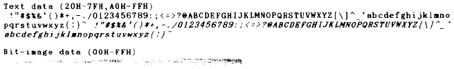
Check that your printer is connected to the computer, and that it is turned
on, loaded with paper, and on-line. Press Y and then
Enter
to continue, or
press
N
and
Enter
to return to the menu.
When you continue the test, the computer checks that the printer is
responding correctly. This test detects whether the printer is off-line or
whether an interface error exists. If no errors occur, the computer sends a
repeating sequence of ASCII h
c
aracters and bit-image data to the printer
until you press any key. The pattern looks like this:
The text data. includes all the characters commonly used by programs
that require foreign languages or graphic characters. If your printer prints
different characters than you see in the illustration, you may need to take
care with certain software. The bit-image data is sent to the printer using a
command (ESC K) compatible with Epson and IBM printers. If this pattern
is printed correctly, you can use the MS-DOS GRAPHICS program to print
out copies of graphics screens.
Note: Even if the test runs only for a short time, your printer may store
many characters in its buffer. To stop printing, turn the printer
off-line.
Hard Disk Drives and Controller Check
Use this option to test the performance of the hard disk drives installed
in your computer. If any errors occur, have the drive checked and serviced by
your dealer.
5-24
When you select option 17 from the DEVICE LIST, you see this menu:
HARD DISK DRIVE(S) AND CONTROLLER CHECK MENU
l -
Seek check
2 -Write, read check
3 - Error detection. and correction
4 - Read, verify check
5 - Run all above checks
0 - Exit
Enter selection number:
check
If you specified to run the hard disk drive check multiple times, this
menu does not display and only the first three tests are performed.
When you select a check from this menu, the program determines the
number of hard disk drives installed in your computer. If you have more
than one drive, then each time you select a test you see this prompt:
Check which drive (C/D)?
Press C or D and then
Enter.
Seek check
This test checks the ability of the read/write heads to locate any part of
the hard disk. This action by a read/write head is called a
seek.
During this
test, each head seeks each cylinder of the disk in sequence, starting from the
center.
Select option 1 from the menu to start this test.
The program displays the number of each cylinder it finds, counting
down from 614 (for a 20MB hard disk) to 0.
The seek is performed by the read/write heads simultaneously, so you
see the cylinder numbers only once. If no errors occur, the menu is displayed.
Write, read check
This check tests the ability of the hard disk drive to read and write data.
The test writes to and reads from each sector of the innermost cylinder of the
disk, using each head.
5-25
Note: This test destroys all data on the innermost cylinder of the selected
hard disk drive. This cylinder is reserved for diagnostics, and is never
used for storage by MS-DOS. Therefore, data created by MS-DOS
is not destroyed.
Select option 2 from the menu to start this test. You see these messages:
The data on the highest physical cylinder may be
destroyed by this check.
Enter Y to start this check.
Enter N to return to the menu.
Press Y and then Enter to continue with the test.
You do not see a cylinder count during the test. If no errors occur, the
program returns to the menu.
If an error is reported, make a note of the code and message. Then use
the Non-destructive surface analysis (option 4 on the HARD DISK
FORMAT MENU) to check the condition of the hard disk. If this analysis
shows no other problems with the disk, follow these steps:
1.
Back up all the files on your hard disk.
2.
Re-format the disk using option 2, Format hard disk, on the
OPERATION MENU.
?. Re-create the MS-DOS partition with FDISK and format it with
SELECT. (See your MS-DOS manual.)
4. Restore your files.
Error detection and correction check
This test checks the ability of the hard disk drive to detect a read/write
error and to correct the data accordingly.
Note: This test destroys some data on the innermost cylinder of the
selected hard disk drive. This cylinder is reserved for diagnostics,
and is never used for storage by MS-DOS. Therefore, data created
by MS-DOS is not destroyed.
Select option 3 from the menu to start this test. You see these messages:
The data on the highest physical cylinder may be
destroyed by this check.
-Enter Y to start this check.
Enter N to return to the menu.
5-26
Press Y and then Enter to continue with the test. If no errors occur, the
menu is displayed.
An error occurs only if the drive is malfunctioning. In this case, back up
all your files, and have the drive serviced immediately. (The drive may be
corrupting your data.)
Read, verify check
This test reads and verifies data from all tracks of the disk, checking each
cylinder and using both heads.
Select option 4 from the menu to start this test.
The program displays the number of each cylinder it finds. For example,
with a 20MB hard disk, the first message you see is:
Current cylinder is
614
The cylinder number counts down to 0.
At the end of the test, you see a table of the results of the test. For
example, for a 20MB hard disk with no bad tracks, you see:
BAD TRACKS .....................
0
READ ERROR TRACKS
..............
0
GOOD
TRACKS
....................2460
Press ENTER to return to the menu
Press
Enter
when you have viewed the table.
Run all above checks
To run all the tests on the menu in sequence, press 5 and then Enter.
When you choose this option, all checks for the hard disk drives and
controller are performed automatically in sequential order. Although you do
not start each test, you must still supply the appropriate responses to progress
from one test to the next. The first prompt you see is:
The data on the highest physical cylinder may be
destroyed by this check.
Enter Y to start this check.
Enter N to return to the menu.
Press Y and then Enter to continue with the test.
5-27
Chapter 6
Moving the Hard Disk
This chapter describes the procedure you use when you plan to move
your computer. Even if you are moving the computer only a short distance,
use option 5, Prepare hard disk for moving, to prevent damage to the hard
disk.
For each hard disk installed in the system, this program ensures that the
read/write heads are moved away from the disk surfaces and locked securely
in position. If the heads are not secured and the computer is subjected to
shock or vibration, the heads may bump the disk surfaces and the drive may
be damaged. At the very least you may lose a considerable amount of data.
To secure the heads, select option 5 from the OPERATION MENU.
You see a screen of information reminding you that the heads will not be
unlocked until the computer is reset or switched off and on again. The screen
is displayed, the heads are moved, and the keyboard is disabled. You can
now turn the computer off and move it to the new location.
You can also secure the heads on your hard disk by executing the
MS-DOS HDSIT command.
Note: If you are using a non-Epson hard disk that does not have a pre-
defined cylinder for securing the heads, you may need to specify the
cylinder number when giving the HDSIT command. To do this, you
must enter the following command at the MS-DOS system prompt:
HDSIT /C xxx
The /C selects the cylinder switch and xxx is the number of the
cylinder where the heads are to be secured. See your hard disk
manual for more information.
6-1
Chapter 7
System-dependent Utilities
This chapter describes the utilities that are included on your diagnostics
diskette. These utilities are used exclusively by your Equity I+ system:
HELP
ROMBIOS
SYSTAT
Each utility is an MS-DOS command. You can copy the commands to your
hard disk or to a directory on another floppy disk. Then you can
execute the commands from the MS-DOS prompt without loading the
diagnostics diskette.
To run the utilities from your diagnostics diskette, select option 0 from
the OPERATION MENU before you run a diagnostics program. You see
this selection on the menu:
0 - Exit to DOS for more utilities
(After you run a diagnostics program, this selection changes to
0-Exit and
reset.
Selecting option 0 at this point resets your computer.)
The HELP Utility
Use the HELP command to ask for information on all the MS-DOS
commands and utility programs. This help function provides useful informa-
tion but is not intended to be a substitute for the MS-DOS manual.
The format of this command is:
HELP [command. . . ]
Type HELP only to see a menu of all commands. Type
HELP
followed by
the name of one or more MS-DOS commands, each separated by a space, to
bypass the menu and display the messages for each command.
7-1

When the menu is displayed, you see this prompt at the bottom of the
screen:
Select command name, Enter to display
command, Esc to Exit
Use the cursor keys to select a command name. (You can only select one
command name at a time from the menu.) When the correct command is
highlighted, press
Enter.
The help screen for the specified command is dis-
played.
If there is more than one page of text, you see the prompt
PgUp
on the
top of the screen. Press
Page Up
(or
Pg Up)
to display the rest of the text.
After reading the help information, press
Esc
to return to the menu.
If you type
HELP
and one or more command names on the command
line, the help information for the first command is displayed. Press ESC to
see the help information for the next command. When you press
E
SC
after
viewing the information for the last command, MS-DOS returns to the
system prompt.
Caution
The help information is stored in the HELP.TXT file. If you copy
HELP.COM to another diskette or to your hard disk, you must also copy
HELP.TXT to the same disk. If they are not in the same path, you can use the
APPEND command to locate HELP.TXT.
Examples
To see help information for the COPY command, type the following
command and press
Enter:
HELP COPY
To see help information for the DISKCOPY and FORMAT commands,
type the following command line and press
Enter:
HELP DISKCOPY FORMAT
To see the help menu, type
HELP only and press
Enter.
7-2
Messages
command not found
You may have misspelled the command name. Press
Enter
to return to
the command prompt and try again.
Failed to open HELP.TXT
HELP could not find the HELP.TXT file. HELP.COM and HELP.TXT
must be in the same directory, or use APPEND to locate the directory
that contains HELP.TXT.
The ROMBIOS Utility
Use this command to display the Epson name and ROM BIOS version
number of the computer you are using.
Because computer systems are frequently updated, it is a good idea to
occasionally check with your dealer for update information. To determine if
a particular update applies to your system, give your dealer the ROM BIOS
version number of your computer.
The format of this command is:
ROMBIOS
Example
Type
ROMBIOS
at the command prompt and press
Enter. You
see a
message similar to:
EQUITY I+ ROM BIOS Version x.xx
The SYSTAT Utility
Use this command to display the system parameters defined in the
CMOS RAM and by the DIP switch settings. You can view these values at
any time.
The format of this command is:
SYSTAT
7-3

Examples
Type SYSTAT only and press
Enter. You
see a screen similar to this:
CPU speed 10 MHz
Memory size Main
640 KB
Display type
Monochrome, 80 col
Coprocessor
8087 not installed
Mass storage Drive A:
360 KB
Drive B:
None
Real-time clock
Time
14:52:03
Date 12-05-1986
Number of RS-232C ports
1
Number of parallel ports 1
Next page --- Enter, Exit --- other
To display the next screen page of information, press
Enter. You
see a
screen similar to this:
Primary serial port Baud rate
9600 bps
Parity
None
Data length 8 bits
Stop bits 1 bit(s)
Secondary serial port
Baud rate
9600 bps
Parity
None
Date length 8 bits
Stop bits 1 bit(s)
Exit --- Esc
7-4
To exit the SYSTAT program, press
Esc.
Messages
Setup error is found
SYSTAT found an error in the way your computer is set up. Use the
Setup program to correct your system parameters.
Checksum error found
This error displays if you run SYSTAT before using Setup to define the
system parameters.
Realtime clock has lost power
The clock battery is losing power or is dead, and needs to be replaced.
7-5

Appendix A
Error Codes and Messages
This appendix lists all the error codes and messages that may appear
during diagnostics checks.
Table A-1.
Error
codes and messages
Error code Message
System board
101 8088 CPU ERROR
102
27128 ROM CHECKSUM ERROR
103
8254 TIMER COUNTER REGISTER ERROR
104
8254 TIMER
COUNTER ERROR
105
8237 DMA CONTROLLER REGISTER ERROR
105
8237 DMA REFRESH ERROR
108
8048 SELFDIAGNOSTIC ERROR
109
8259 INTERRUPT CONTROLLERERROR
111
146818 CMOS BATTERYERROR
112
146818 CMOS CHECKSUMERROR
113
8088 INSTRUCTIONERROR
Memory
201
MEMORY/PARITY ERROR
Keyboard
301
8048 ERROR
302
NON-STANDARDOR DEFECTIVE KEYBOARD
Monochrome display adapter and CRT
401
V-RAM ERROR
402 VIDEO SIGNAL ALWAYS HIGH/LOW
403
ATTRIBUTEERROR
404
CHARACTERSET ERROR
A-1

Table A-1. Error codes and
messages
(continued)
Error code
Message
Color graphics adapter and CRT
501
V-RAM ERROR
503
ATTRIBUTEERROR
504
CHARACTERSET ERROR
505
40-COLUMN CHARACTERSET ERROR
506
320
x
200
GRAPHICS MODE ERROR
507
640
x 200 GRAPHICS MODE ERROR
508
SCREEN PAGING ERROR
509
LIGHT PEN ERROR
510
COLOR VIDEO ERROR
Floppy disk drives and controller
601
FLOPPYDISK CONTROLLERERROR
602
SEQUENTIAL SEEK ERROR
603
RANDOM SEEK ERROR
604
WRITEERROR
605
READ ERROR
Math coprocessor (8087)
701
COPROCESSORNOT INSTALLED
702
COPROCESSOR INITIALIZEERROR
703
COPROCESSOR INVALID OPERATION MASK ERROR
704
COPROCESSOR ST FIELD ERROR
705
COPROCESSOR COMPARISON ERROR
706 COPROCESSOR ZERO DIVIDE MASK ERROR
707
COPROCESSOR ADDITION ERROR
708
COPROCESSORSUBTRACTION ERROR
709
COPROCESSOR MULTIPLICATION ERROR
710
COPROCESSOR PRECISION ERROR
Parallel port
901
ERROR PIN p
Parallel port on video adapter
8101
ERROR PIN p
A-2

Table A-1 Error codes and
messages
(continued)
Error code
Message
Serial port (RS-232C)
1101 ERROR DTR DSR, DSR ALWAYS HIGH/LOW
1101 ERROR RTS CTS, CTS ALWAYS HIGH/LOW
1102 TIMEOUT ERROR
1103
VERIFY ERROR
Alternate serial port
1201 ERROR DTR DSR, DSR ALWAYS HIGH/LOW
1201 ERROR RTS CTS, CTS ALWAYS HIGH/LOW
1202 TIMEOUT ERROR
1203
VERIFY ERROR
Dot-matrix printer
1401
status : error- type
Hard disk drives and controller
1701 SEEK ERROR
1702 WRITE ERROR
1703
READ ERROR
1705 ERROR DETECTION ERROR
1706 ERROR CORRECTION ERROR
A-3
Appendix B
Power-on Diagnostics
The built-in memory (ROM) of your computer contains a series of diag-
nostics programs. These programs are run automatically by the system every
time you turn on the power. The diagnostics programs check the internal
devices such as ROM, RAM, keyboard controller, timer, video controller,
and floppy disk driver.
When you turn on the power, the tests described in this appendix are
performed. If an error is found, a specific error number and error message are
displayed. If the error is serious, the computer cancels further checking and
halts system initialization. The error message remains on the screen but the
computer is inoperable.
If the error is not serious, the computer displays an error message and
waits for you to resume further checking. You see this prompt:
F1 key to resume
Write down the error message and code number, and then press F1 to
resume. Report the error message and code number to your dealer when
requesting repairs.
System Device Check
The computer first checks its internal devices such as the ROM. If a
malfunction is found, the computer displays an error message. In some cases,
it may halt with no further information. If this happens, contact your dealer
as soon as possible.
If a fault in the main board is found, the computer stops and this error
message displays:
101-System board error
Give this error number to your dealer.
If an I/O or checksum error occurs, you see this message:
xxxx0 ROM error
where xxxx is the number of the segment of the bad I/O ROM on an option
card.
B-1
Clock and CMOS RAM Check
When the system device check is completed successfully, the computer
checks the timer and CMOS RAM. If the information contained in the
RAM does not match the actual system installation, you see this message:
161-System options not set
(Run SETUP in DIAGNOSTICS)
The information stored in the CMOS RAM must be corrected. Run the
Setup program provided on the diagnostics diskette to correct the installa-
tion information.
If the system clock has not been set, this message is displayed:
163-Time & Date not set
(Run SETUP in DIAGNOSTICS)
RAM Check
The computer now begins to check the RAM installed in both the main
board and option cards. During this check, this message is displayed:
xxx KB OK
where XXX indicates the amount of memory in which no malfunction is
found. This value increases continuously by 64KB up to the amount of
RAM installed on the main board, which is 640KB. If the computer detects
an error in the first 64KB area, an error message is displayed and the com-
puter halts with no further information.
If there are faulty RAM chips in your system, you see this message:
xxxx0 201-Memory error
Keyboard Controller and Keyboard Check
The computer checks the keyboard controller and keyboard for prob-
lems such as failure of one of the keys to release. If there are any errors in the
connection between the keyboard and the computer, this error message is
displayed:
301-Keyboard error
When a number (
XX
) precedes this message, the number represents the key
(in hexadecimal) that is causing the error. This message may occur after a
keyboard reset
(Ctrl Alt Del)
and
does not necessarily indicate a problem.
B-2
Floppy Disk Drive Seek Check
The computer checks its floppy disk drives by searching the rend/write
heads for any malfunction.
If any seek errors are found, you see this message:
601-Diskette error
If this error occurs, confirm that the system diskette is inserted into drive A.
If this number still appears after you insert the diskette, you may then want
to run the System diagnostics and select option 6 from the DEVICE LIST If
the error persists, consult your dealer about having the drive repaired.
B-3
Index
A
Adapter,
Color graphics, 5-11—12
Monochrome display, 5-8—9
Alternate serial port check, 5-23
Analysis, hard disk,
Destructive surface, 3-6
Non-destructive surface, 3-8
Attribute check,
Monochrome adapter, 5-9
Color graphics adapter, 5-12
B
Bad tracks, hard disk, 3-2—8
Board checks, system, 5-6
Boot system, 1-4, 2-2—3
C
Caps Lock, 5-8
Character set checks,
Color graphics adapter, 5-13—14
Monochrome adapter, 5-10
Clock,
Check, B-2
Real-time, 2-1—4
CMOS RAM, 2-1—3, 5-6, B-2
Color graphics,
Adapter and CRT checks,
5-11—18
Adapter check, 5-11—12
Attribute check, 5-12
Character set check,
40-column, 5-14
80-column, 5-13
Color video check, 5-17
Graphics mode check,
320 x 200, 5-14
640 x 200, 5-15
Light pen check, 5-16—17
Screen paging check, 5-16
Sync check, 5-18
Color video check, 5-17
Commands, See MS-DOS
commands
Conditional format (normal), hard
disk, 3-3—4
Coprocessor (8087), 5-21
CPU chip (8088), 5-6
CRT, 5-8, 5-11
D
DATE command, 2-1, 2-3
Date, setting, 2-1, 2-3-4
Destructive surface analysis, hard
disk, 3-6—7
DEVICE LIST, 5-2—6, 5-21
DIAGSYS, 1-3
DIP switches, 5-2, 5-4, 5-6, 5-8, 5-11
5-21—22, 7-3
Diskette, format, 4-1
Disk drives, 3-20, 5-18—21, 5-24—27
Display, Monitor, 1-4, 5-8—18
Dot-matrix printer check, 5-23—24
Error,
E
Codes, A-1—3
Correction check, hard disk, 5-26
Detection check, hard disk, 5-26
Messages, A-1—3
Resuming, 5-5
Index-1
F
FDISK, 5-26
Flagged tracks, 3-2—8
Floppy disk,
Controller check, 5-18—21
Drive check, 5-18-21, B-3
Formatting, 4-1
Random seek check, 5-19
Sequential seek check, 5-19
Speed check, 5-20, B-3
Write, read check, 5-19
Format,
Diskette, 4-1
Hard disk, 3-1—8
HARD DISK FORMAT MENU,
3-1—2, 3-4, 3-8
G
Graphics mode check, 5-11, 5-14—15
H
Hard disk,
Conditional format (normal),
3-3—4
Controller checks, 5-24—27
Destructive surface analysis, 3-6
Drives, 5-24—27
Error detection and correction
check, 5-26
Formatting/checking options, 3-1
Moving, 6-1
Non-destructive surface analysis,
3-8
Read, verify check, 5-27
Seek check, 5-25
Unconditional format, 3-5
Write, read check, 5-25—26
HARD DISK FORMAT MENU,
3-1—2, 3-4, 3-8
HDSIT, 1-3, 6-1
HELP utility, 7-1—3
I
Interface, printer, 5-21
K
Keyboard check, 5-7—8, B-2
L
Light pen check, 5-16—17
M
Math coprocessor (8087) check,
5-21
Messages, A-1—3
Memory check, 5-6—7
Mode, graphics, 5-11, 5-14—15
Monochrome display,
Adapter and CRT checks,
5-8—11
Adapter check, 5-9
Attribute check, 5-9
Character set check, 5-10
Checks, 5-8—11
Video check, 5-10
Sync check, 5-11
Moving hard disk, 6-1
MS-DOS, 1-2—3, 2-1, 2-3, 2-5, 3-1,
4-1, 5-6, 5-24, 5-26
MS-DOS, commands, 2-1, 2-3, 3-1,
4-1, 5-26, 6-1, 7-1—3
N
Non-destructive surface analysis,
hard disk, 3-8
Num Lock, 5-8
Index-2
O
OPERATION MENU, 1-2-3, 2-1,
2-3, 3-1, 4-1, 5-1—2, 5-26, 6-1, 7-1
P
Paging, screen check, 5-16
Parallel port check, 5-21—22
Power-on diagnostics (self test), 1-1,
B-1—3
Primary serial port, 2-2, 2-5—6
Printer interface check, 5-21—22
Printer, dot-matrix, 5-23—24
Program, Setup, Intro-1, 1-2—3,
2-1—6
R
RAM,
Checks, 5-6—7, B-2
CMOS, 2-1—3, 5-6, B-2
Video, 5-9
Random seek check, 5-19
Read, verify, 5-27
Real-time clock, setting, 2-1—4
Reset system, 1-3
Resume from error,
Power-on diagnostics, B-1
System diagnostics, 5-5
ROMBIOS utility, 7-3
ROM system, 5-6
S
Screen paging check, 5-16
Scroll Lock, 5-8
Secondary serial port, 2-2, 2-5—6
Seek check, 5-25, B-3
Self test, 1-1, B-1—3
Sequential seek check, 5-19
Serial port (RS-232C) check,
5-22—23
Serial port settings, 1-1
Setting date, 2-3—4
Setting real-time clock, 2-1—4
Setting time, 2-3—4
SETUP command, 1-3, 2-1
Setup program, Intro-1, 1-2—3,
2-1—6
Starting diagnostics, 1-1
Speed check, 5-20
Switches, DIP 5-2, 5-4, 5-6, 5-8, 5-11,
5-22, 7-3
Sync check, 5-11, 5-18
SYSTAT utility, 1-1, 1-3, 7-1, 7-3—5
System,
Board check, 5-6
Device check, B-1
Diagnostics, 5-1—27
ROM, 5-6
Setting real-time clock, 2-3—4
Setup, Intro-1, 1-2—3, 2-1—6
Utilities, Intro-1 -2, 1-3, 7-1—5
T
Test, selecting, 5-4—5
TIME command, 2-3
U
Unconditional format, 3-5
Utilities, system-dependent
HELP, Intro-1—2, 1-3, 7-1—3
ROMBIOS, Intro-1—2, 1-3, 7-3
SYSTAT, Intro-1 -2, 1-3, 7-3
V
Video check,
Color graphics, 5-17
Monochrome display, 5-10
Video RAM, 5-9
W
Write, read check, 5-19, 5-25—26
Index-3
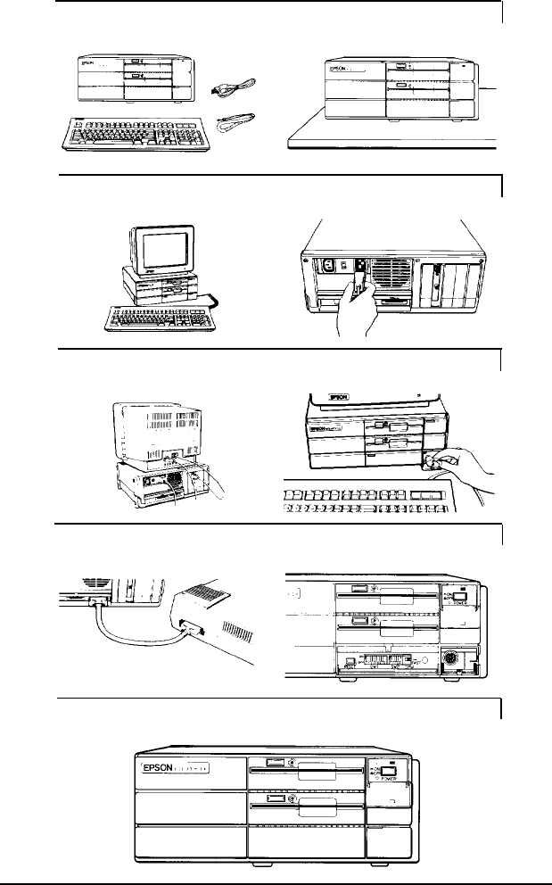
1
Unpacking
your Computer
3
Arranging
the Components
5
Connecting
the Video Monitor
2
Choosing
a Location
4
Connecting
the Power Cord
6
Connecting
the Keyboard
7
Connecting
a Printer
8
Setting
the DIP Switches
9
Turning on
the Computer