Epson TM FX2180 SunG+_1 User Manual To The 420af76a 2675 4d94 947f Fe49d324600c
User Manual: Epson TM-FX2180 to the manual
Open the PDF directly: View PDF ![]() .
.
Page Count: 103 [warning: Documents this large are best viewed by clicking the View PDF Link!]
- Home
- Previous Menu
- FCC COMPLIANCE STATEMENT
- PRECAUTIONS
- PREFACE
- Table of Contents
- Chapter 1: PRODUCT DESCRIPTION
- 1.1 Specifications
- 1.1.1 Printing Specifications
- 1.1.2 Print Speed and Printable Columns
- 1.1.3 Resolution
- 1.1.4 Printable Area
- 1.1.5 Paper Feed Specifications
- 1.1.6 Paper Specifications
- 1.1.7 Interface Specifications
- 1.1.8 Software Specifications
- 1.1.9 Environmental Conditions
- 1.1.10 Electrical Specifications
- 1.1.11 Physical Specifications
- 1.1.12 Reliability
- 1.1.13 Safety Approvals
- 1.1.14 CE Marking
- 1.1.15 Acoustic Noise
- 1.1.16 Ribbon Cartridge
- 1.2 Operation
- 1.3 Special Functions
- 1.4 Consumables and Options
- 1.1 Specifications
- Chapter 2: OPERATING PRINCIPLES
- Chapter 3: TROUBLESHOOTING
- Chapter 4: DISASSEMBLY AND ASSEMBLY
- 4.1 Overview
- 4.2 Disassembly and Assembly
- 4.2.1 Preparing to Disassemble the Printer
- 4.2.2 Removing the Panel Board Assembly
- 4.2.3 Removing the Print Head
- 4.2.4 Removing the HP Sensor
- 4.2.5 Removing the PW Sensor Assembly
- 4.2.6 Removing the Ribbon Mask
- 4.2.7 Removing the Upper Housing Assembly
- 4.2.8 Removing the Platen Assembly
- 4.2.9 Removing the Platen Gear
- 4.2.10 Removing the Case Open Sensor Assembly
- 4.2.11 Removing the Printer Mechanism
- 4.2.11.1 Removing the CR Motor Assembly
- 4.2.11.2 Removing the PF Motor Assembly
- 4.2.11.3 Removing the PG Sensor Assembly
- 4.2.11.4 Removing the Right Sub Frame Assembly
- 4.2.11.5 Removing the Right Frame Assembly
- 4.2.11.6 Disassembling the Right Frame Assembly
- 4.2.11.7 Removing the Left Frame Assembly
- 4.2.11.8 Removing the Ribbon Drive (RD) Assembly
- 4.2.11.9 Removing the CR Assembly
- 4.2.11.10 Removing the Rear PE Sensor Assembly
- 4.2.11.11 Removing the Front PE Sensor Assembly
- 4.2.11.12 Removing the Main Board Assembly
- 4.2.11.13 Removing the Power Supply Board Assembly
- Chapter 5: ADJUSTMENTS
- Chapter 6: MAINTENANCE
- APPENDIX

6(59,&(0$18$/
9 Pin Impact Dot Printer
EPSON FX-2180
TM-FX2180
®

EPSON FX-2180 Service Manual
1
FCC COMPLIANCE STATEMENT
FOR AMERICAN USERS
This equipment has been tested and found to comply with the limits for a Class B digital device, pursuant to Part 15 of the FCC Rules. These limits are designed to provide reasonable
protection against harmful interference in a residential installation. This equipment generates, uses, and can radiate radio frequency energy and, if not installed and used in accordance
with the instructions, may cause harmful interference to radio and television reception. However, there is no guarantee that interference will not occur in a particular installation. If this
equipment does cause interference to radio and television reception, which can be determined by turning the equipment off and on, the user is encouraged to try to correct the
interference by one or more of the following measures:
• Reorient or relocate the receiving antenna.
• Increase the separation between the equipment and receiver.
• Connect the equipment into an outlet on a circuit different from that to which the receiver is connected.
• Consult the dealer or an experienced radio/TV technician for help.
WARNING
The connection of a non-shielded equipment interface cable to this equipment will invalidate the FCC Certification of this device and may cause interference levels that exceed the limits
established by the FCC for this equipment. It is the responsibility of the user to obtain and use a shielded equipment interface cable with this device. If this equipment has more than one
interface connector, do not leave cables connected to unused interfaces.
Changes or modifications not expressly approved by the manufacturer could void the user's authority to operate the printer.
FOR CANADIAN USERS
This Class B digital apparatus meets all requirements of the Canadian Interference-Causing Equipment Regulations.
Cet appareil numérique de la classe B respecte toutes les exigences du Règlement sur le materiel brouilleur du Canada.
COPYRIGHT NOTICE
All rights reserved. No part of this publication may be reproduced, stored in a retrieval system, or transmitted in any form or by any means, electronic, mechanical, photocopying,
recording, or otherwise, without the written permission of Epson America, Inc. No patent liability is assumed with respect to use of the information contained herein. Neither is any
liability assumed for damages resulting from the use of the information contained herein. While every precaution has been taken in the preparation of this book, Epson America, Inc.
assumes no responsibility for errors and omissions.
Neither Epson America, Inc., nor its affiliates shall be liable to the purchaser of this product or third parties for damages, losses, costs, or expenses incurred by purchaser or third parties
as a result of: accident, misuse, or abuse of this product or unauthorized modifications, repairs, or alterations to this product.
Epson America, Inc., shall not be liable against any damages or problems arising from the use of any options or any consumable products other than those designated as Original
EPSON Products or EPSON-Approved Products by Seiko Epson Corporation.

EPSON FX-2180 Service Manual
2
TRADEMARKS
EPSON® and ESC/P® are registered trademarks of Seiko Epson Corporation.
General Notice: Other product names used herein are for identification purposes only and may be trademarks of their respective companies. EPSON disclaims any and all rights in
those marks.
Copyright © 1998 Epson America, Inc.
20770 Madrona Avenue
Torrance, CA 90503

EPSON FX-2180 Service Manual
3
PRECAUTIONS
There are cautionary notes throughout the text to help you avoid personal injury or equipment damage.
WARNING
Signals a precaution which, if ignored, could result in serious or fatal personal injury. Great caution should be exercised in performing procedures preceded by a
WARNING heading.
CAUTION
Signals a precaution which, if ignored, could result in damage to equipment.
Always observe the measures listed below when performing repair or maintenance procedures.
WARNING
1. Always disconnect the product from both the power source and host computer before performing any maintenance or repair procedure.
2. No work should be performed on the unit by persons unfamiliar with basic safety measures dictated for all electronics technicians in their line of work.
3. In performing testing described in this manual, do not connect the unit to a power source until instructed to do so. When the power supply cable must be connected,
use extreme caution in working on the power supply and other electronic components.
CAUTION
1. Repairs on EPSON products should be performed only by an EPSON-certified repair technician.
2. Make certain that the source voltage is the same as the rated voltage listed on the serial number/rating plate. If the EPSON product has a primary AC rating
different from the available power source, do not connect it to the power source.
3. Always verify that the EPSON product has been disconnected from the power source before removing or replacing printed circuit boards and/or individual chips.
4. To protect sensitive microprocessors and circuitry, use static discharge equipment, such as anti-static wrist straps, when accessing internal components.
5. Replace malfunctioning components only with those components recommended by the manufacturer; introduction of second-source ICs or other nonapproved
components may damage the product and void any applicable EPSON warranty.

EPSON FX-2180 Service Manual
4
PREFACE
This manual describes the basic functions, theory of electrical and mechanical operations, and maintenance and repair procedures of the EPSON
FX-2180. The instructions and procedures included herein are intended for the experienced repair technicians, and attention should be given to the precautions on the
preceding page. The chapters are organized as follows:
Chapter 1. Product Description
Provides specifications and a general overview of the printer.
Chapter 2. Operating Principles
Describes the electrical and mechanical operation of the printer.
Chapter 3. Troubleshooting
Provides step-by-step troubleshooting procedures.
Chapter 4. Disassembly and Assembly
Provides step-by-step instructions on disassembling and assembling the
printer.
Chapter 5. Adjustments
Provides Epson-approved adjustment methods.
Chapter 6. Maintenance
Provides preventive maintenance procedures and lists the Epson-approved
lubricants and adhesives required for servicing the printer.
Appendix
Provides the following additional reference information:
• Connector pin assignments
• Circuit board components layouts
• Circuit board schematics
• Exploded diagrams

EPSON FX-2180 Service Manual
5
Table of Contents
1. Product Description.............................................................................................................1-1
1.1 Specifications.........................................................................................................1-1
1.1.1 Printing Specifications.............................................................................1-1
1.1.2 Print Speed and Printable Columns ........................................................1-1
1.1.3 Resolution ...............................................................................................1-2
1.1.4 Printable Area .........................................................................................1-2
1.1.5 Paper Feed Specifications ......................................................................1-5
1.1.6 Paper Specifications ...............................................................................1-5
1.1.7 Interface Specifications...........................................................................1-8
1.1.8 Software Specifications...........................................................................1-8
1.1.9 Environmental Conditions .......................................................................1-9
1.1.10 Electrical Specifications.........................................................................1-9
1.1.11 Physical Specifications..........................................................................1-9
1.1.12 Reliability...............................................................................................1-9
1.1.13 Safety Approvals.................................................................................1-10
1.1.14 CE Marking..........................................................................................1-10
1.1.15 Acoustic Noise.....................................................................................1-10
1.1.16 Ribbon Cartridge .................................................................................1-10
1.2 Operation.............................................................................................................1-10
1.2.1 Control Panel ........................................................................................1-10
1.2.1.1 Buttons ...................................................................................1-10
1.2.1.2 LEDs.......................................................................................1-11
1.2.1.3 Beeper....................................................................................1-12
1.2.2 Paper Release Lever Positions.............................................................1-12
1.2.3 Paper Thickness Lever Positions ..........................................................1-13
1.3 Special Functions ................................................................................................1-13
1.3.1 Printing a Self Test................................................................................1-13
1.3.2 Turning on the Double-strike Mode .......................................................1-13
1.3.3 Using the Bidirectional Adjustment Mode..............................................1-14
1.3.4 Changing Default Settings ....................................................................1-14
1.3.5 Printing a Hex Dump .............................................................................1-15
1.3.6 Clearing the EEPROM...........................................................................1-15
1.3.6.1 Clearing the Ribbon Cartridge Replacement Counter.............1-15
1.4 Consumables and Options...................................................................................1-15
1.4.1 Consumables ........................................................................................1-15
1.4.2 Options..................................................................................................1-15

EPSON FX-2180 Service Manual
6
2. Operating Principles............................................................................................................2-1
2.1 Overview................................................................................................................2-1
2.1.1 Printer Mechanism...................................................................................2-1
2.1.2 Power Supply Circuit...............................................................................2-2
2.1.2.1 Power Supply Circuit Operation................................................2-2
2.1.3 Control Circuit..........................................................................................2-3
2.1.3.1 Control Circuit Operation ..........................................................2-3
3. Troubleshooting...................................................................................................................3-1
3.1 Overview................................................................................................................3-1
3.2 Troubleshooting Information ..................................................................................3-1
3.2.1 Print Head ...............................................................................................3-1
3.2.2 Sensors...................................................................................................3-2
3.2.3 Motors .....................................................................................................3-3
3.2.4 Error Conditions ......................................................................................3-3
3.3 Unit Level Troubleshooting ....................................................................................3-4
3.4 Repairing the Power Supply Board........................................................................3-7
3.5 Repairing the Main Board Assembly......................................................................3-9
3.6 Repairing the Printer Mechanism.........................................................................3-11
4. Disassembly and Assembly.................................................................................................4-1
4.1 Overview................................................................................................................4-1
4.1.1 Precautions .............................................................................................4-1
4.1.2 Tools .......................................................................................................4-1
4.1.3 Specifications for Screws........................................................................4-2
4.1.4 Service Check After Repair.....................................................................4-3
4.2 Disassembly and Assembly ...................................................................................4-4
4.2.1 Preparing to Disassemble the Printer......................................................4-5
4.2.2 Removing the Panel Board Assembly.....................................................4-6
4.2.3 Removing the Print Head ........................................................................4-7
4.2.4 Removing the HP Sensor........................................................................4-8
4.2.5 Removing the PW Sensor Assembly ......................................................4-8
4.2.6 Removing the Ribbon Mask ....................................................................4-9
4.2.7 Removing the Upper Housing Assembly...............................................4-10
4.2.8 Removing the Platen Assembly.............................................................4-11
4.2.9 Removing the Platen Gear....................................................................4-12
4.2.10 Removing the Case Open Sensor Assembly ......................................4-12
4.2.11 Removing the Printer Mechanism........................................................4-13
4.2.11.1 Removing the CR Motor Assembly.......................................4-15
4.2.11.2 Removing the PF Motor Assembly........................................4-16
4.2.11.3 Removing the PG Sensor Assembly.....................................4-17
4.2.11.4 Removing the Right Sub Frame Assembly ...........................4-18
4.2.11.5 Removing the Right Frame Assembly...................................4-18

EPSON FX-2180 Service Manual
7
4.2.11.6 Disassembling the Right Frame Assembly............................4-19
4.2.11.7 Removing the Left Frame Assembly.....................................4.21
4.2.11.8 Removing the Ribbon Drive Assembly..................................4-22
4.2.11.9 Removing the CR Assembly.................................................4-23
4.2.11.10 Removing the Rear PE Sensor Assembly ..........................4.25
4.2.11.11 Removing the Front PE Sensor Assembly..........................4-26
4.2.11.12 Removing the Main Board Assembly..................................4-26
4.2.11.13 Removing the Power Supply Board Assembly....................4-28
5. Adjustments.........................................................................................................................5-1
5.1 Adjustment Overview.............................................................................................5-1
5.1.1 Required Adjustments.............................................................................5-1
5.1.2 Adjustment Tools.....................................................................................5-1
5.2 Adjusting and Resetting the Printer .......................................................................5-2
5.2.1 Platen Gap/Parallelism Adjustment.........................................................5-2
5.2.2 Bidirectional Print Alignment (Bi-d) Adjustment.......................................5-4
5.2.2.1 Performing the Bi-d Adjustment Using the Settings Diskette ....5-5
5.2.2.2 Performing the Bi-d Adjustment from the Control Panel...........5-6
5.2.3 Factory Settings ......................................................................................5-7
5.2.4 TPE Level Reset .....................................................................................5-8
6. Maintenance........................................................................................................................6-1
6.1 Preventive Maintenance ........................................................................................6-1
6.2 Lubrication .............................................................................................................6-1
Appendix ................................................................................................................................ A-1
A.1 Connector Summary............................................................................................. A-1
A.2 Circuit Board Component Layout Diagrams ......................................................... A-5
A.3 Circuit Board and Exploded Diagrams.................................................................. A-7

PRODUCT DESCRIPTION
&+$37(5
EPSON FX-2180 Service Manual Chapter 1 Product Description
1-1
1.1 Specifications
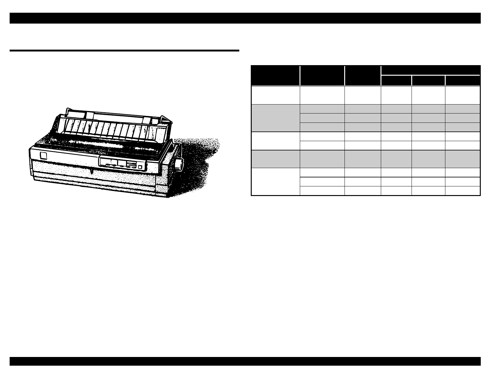
This section provides detailed specifications for the EPSON® FX-2180
impact dot matrix printer. The FX-2180 is based on the FX-2170 printer,
and its main components are very similar to those of the FX-2170.
However, the FX-2180 provides a faster printing speed, better multi-part
form printing, and other enhancements.
Figure 1-1. Exterior View of the FX-2180
1.1.1 Printing Specifications
Print method: Impact dot matrix
Number of pins: 18
Print pin arrangement: 9 × 2
Print pin diameter: 0.0114 inch (0.29 mm)
Color: Black
Print direction: Bidirectional with logic seeking
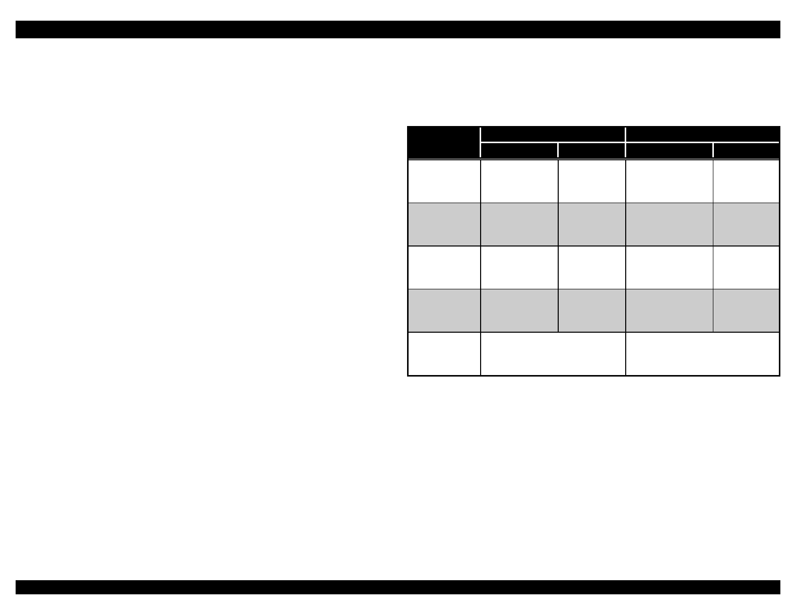
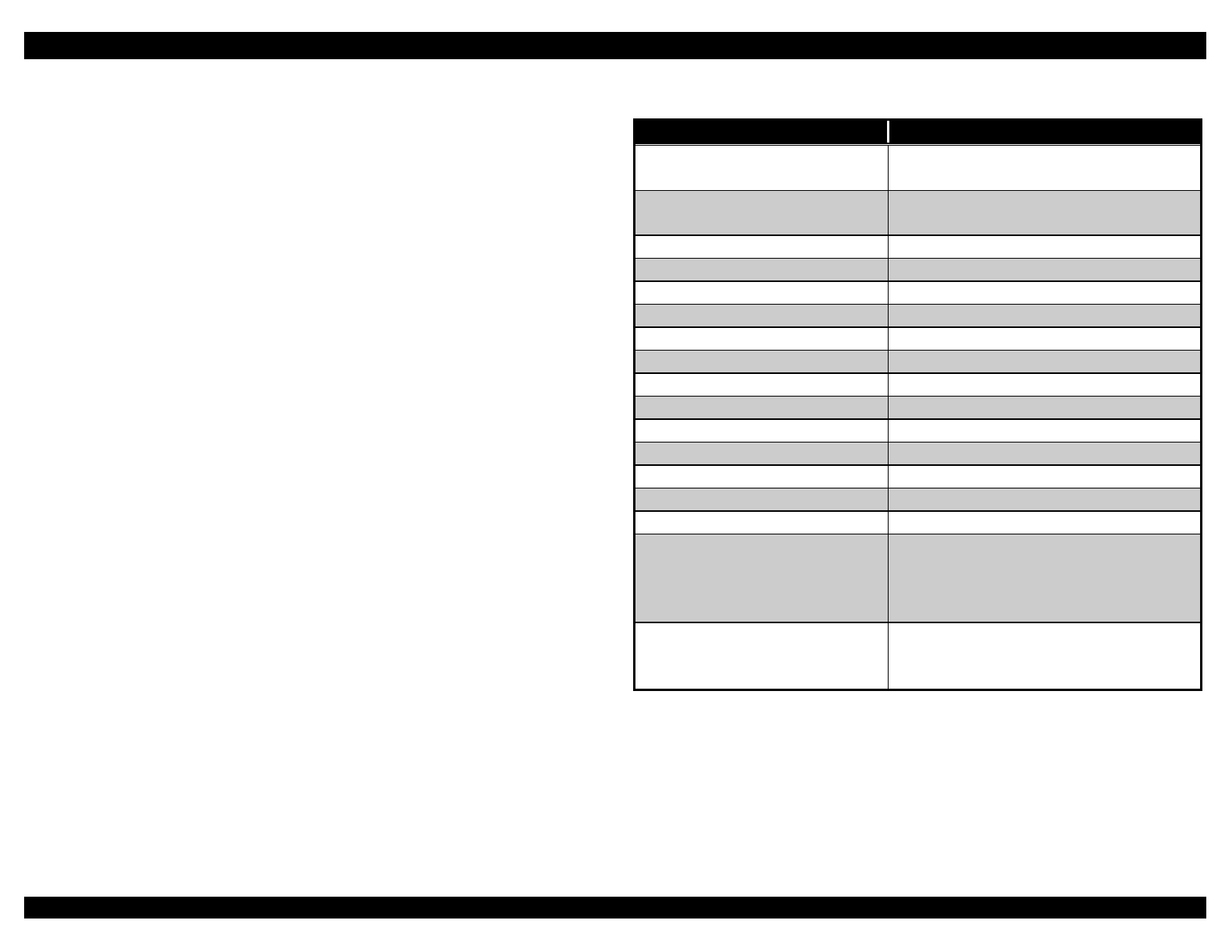
1.1.2 Print Speed and Printable Columns
Table 1-1. Print Speed and Printable Columns
Printing Speed (cps)
Printing
Mode Character
Pitch (cpi) Printable
Columns Normal Copy 1* Copy 2**
High speed
draft
10 136 506 439 337
10 136 380 330 284
12 163 455 396 341
Draft
15 204 380 285 285
17 233 325 282 244Draft
condensed 20 272 380 330 284
Draft
emphasized
10 136 190 165 142
10 136 95 82 71
12 163 114 99 85
NLQ
15 204 94 71 31
* Paper thickness lever set to 3.
** Paper thickness lever set to 4 or more.
Note:
When the power supply voltage drops to the lower limit, the printer stops
printing, and then starts printing again on the same line at a slower
speed.
When the print head temperature rises to the upper limit, the printer
stops printing. When the head temperature returns to the normal level,
the printer starts printing again at a slower speed.
EPSON FX-2180 Service Manual Chapter 1 Product Description
1-2
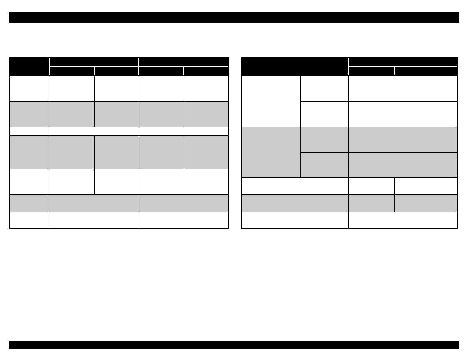
1.1.3 Resolution
Table 1-2. Resolution
Printing Mode Horizontal
Density (dpi) Vertical
Density (dpi) Adjacent Dot
Printed
High speed draft 90 72 No
Draft 120 72 No
Draft condensed 240 720 No
Draft emphasized 120 72 Yes
NLQ 240 144 No
60, 72, 80, 90,
or 120
72 YesBit image
120 or 240 72 No
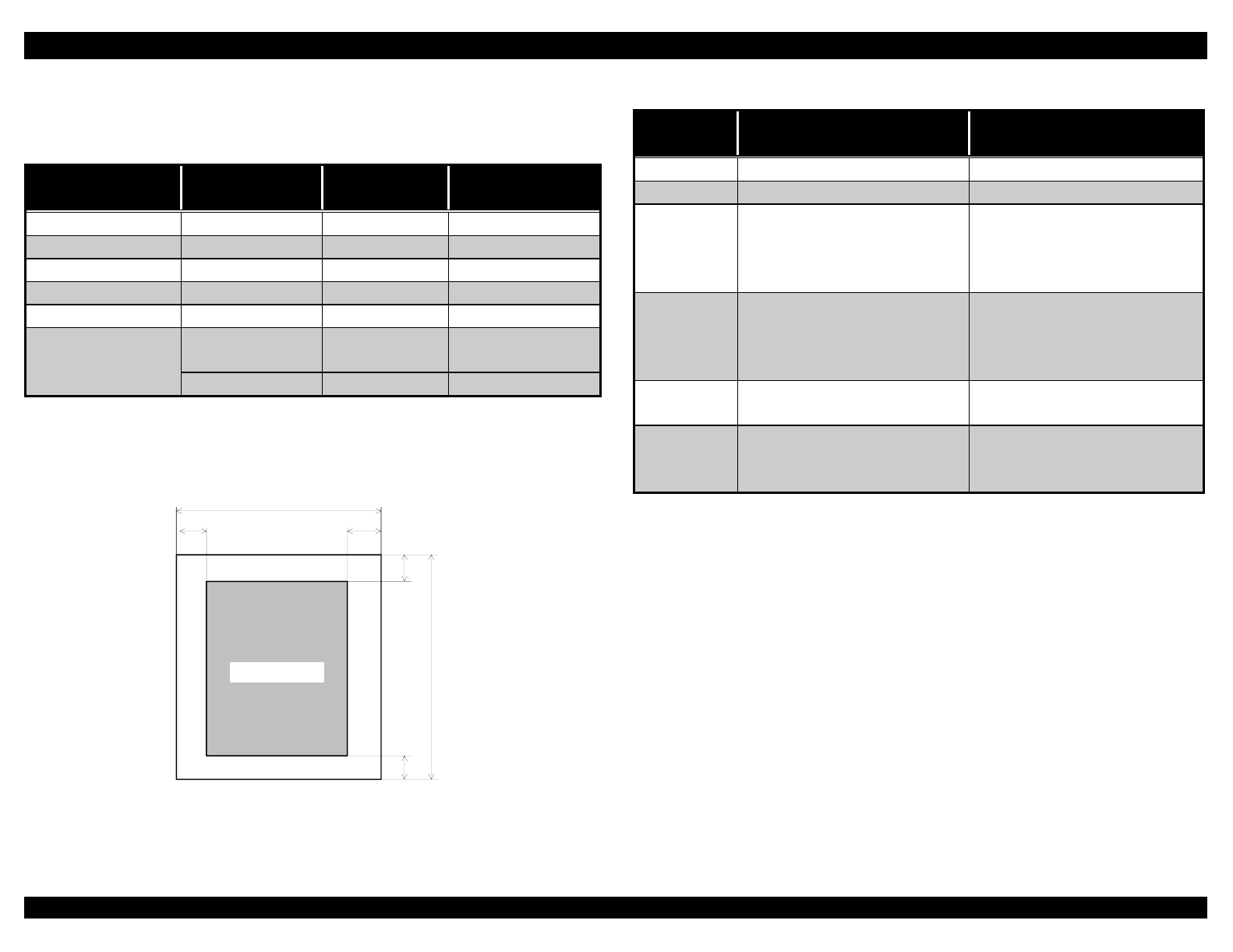
1.1.4 Printable Area
Single sheets
printable area
PW
LM RM
PL
TM
BM
Figure 1-2. Printable Area for Single Sheets
Table 1-3. Printable Area for Single Sheets
Single Sheets Single-sheet Multi-part
Forms
PW (width) See Table 1-8 See Table 1-9
PL (length) See Table 1-8 See Table 1-9
LM (left
margin)
0.12 in. (3 mm) or more
(PW ≤ 14.33 in. or 364 mm)
0.98 in. (25 mm) or more
(PW = 16.5 in. or 420 mm)
0.12 in. (3 mm) or more
(PW ≤ 14.33 in. or 364 mm)
0.98 in. (25 mm) or more
(PW = 16.5 in. or 420 mm)
RM (right
margin)
0.12 in. (3 mm) or more
(PW ≤ 14.33 in. or 364 mm)
0.98 in. (25 mm) or more
(PW = 16.5 in. or 420 mm)
0.12 in. (3 mm) or more
(PW ≤ 14.33 in. or 364 mm)
0.98 in. (25 mm) or more
(PW = 16.5 in. or 420 mm)
TM (top
margin)
0.17 in. (4.2 mm) or more 0.17 in. (4.2 mm) or more
BM
(bottom
margin)
0.17 in. (4.2 mm) or more 0.17 in. (4.2 mm) or more
Note: The maximum horizontal printable area is 13.6 inches (345.2 mm).
EPSON FX-2180 Service Manual Chapter 1 Product Description
1-3
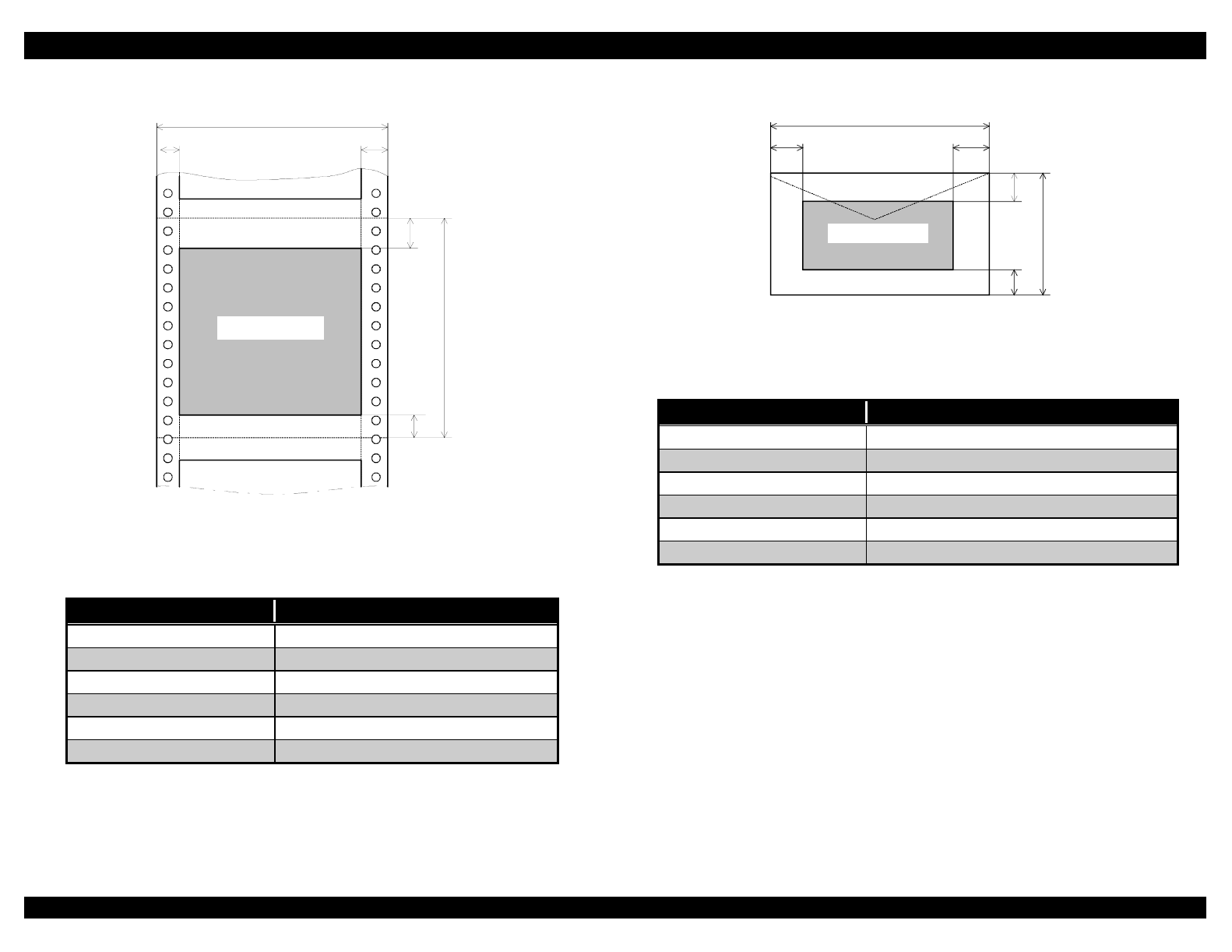
Continuous paper PW
LM RM
PL
TM
BM
printable area
Figure 1-3. Printable Area for Continuous Paper
Table 1-4. Printable Area for Continuous Paper
Continuous Paper
PW (width) See Table 1-12
PL (length) See Table 1-12
LM (left margin) 0.12 in. (3 mm) or more
RM (right margin) 0.12 in. (3 mm) or more
TM (top margin) 0.17 in. (4.2 mm) or more
BM (bottom margin) 0.17 in. (4.2 mm) or more
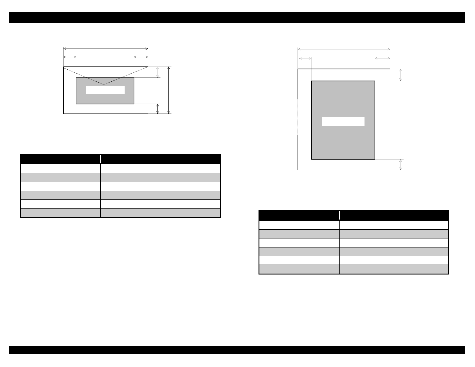
Envelopes
printable area
PW
LM RM
PL
TM
BM
Figure 1-4. Printable Area for Envelopes
Table 1-5. Printable Area for Envelopes
Envelopes
PW (width) See Table 1-10
PL (length) See Table 1-10
LM (left margin) 0.12 in. (3 mm) or more
RM (right margin) 0.12 in. (3 mm) or more
TM (top margin) 0.17 in. (4.2 mm) or more
BM (bottom margin) 0.17 in. (4.2 mm) or more
EPSON FX-2180 Service Manual Chapter 1 Product Description
1-4
Postcards
printable area
PW
LM RM
PL
TM
BM
Figure 1-5. Printable Area for Postcards
Table 1-6. Printable Area for Postcards
Postcards
PW (width) See Table 1-11
PL (length) See Table 1-11
LM (left margin) 0.12 in. (3 mm) or more
RM (right margin) 0.12 in. (3 mm) or more
TM (top margin) 0.17 in. (4.2 mm) or more
BM (bottom margin) 0.17 in. (4.2 mm) or more
Roll paper PW
LM RM
TM
BM
printable area
Figure 1-6. Printable Area for Roll Paper
Table 1-7. Printable Area for Roll Paper
Roll Paper
PW (width) See Table 1-14
PL (length) See Table 1-14
LM (left margin) 0.12 in. (3 mm) or more
RM (right margin) 0.12 in. (3 mm) or more
TM (top margin) 0.17 in. (4.2 mm) or more
BM (bottom margin) 0.17 in. (4.2 mm) or more
EPSON FX-2180 Service Manual Chapter 1 Product Description
1-5
1.1.5 Paper Feed Specifications
Standard feeding Friction front, rear
methods: Push tractor front, rear
Pull tractor front, rear, bottom
Push and pull tractor front, rear
Optional feeding Cut-sheet feeder (CSF),
methods: bin 1 or bin 2 rear (top)
Roll paper holder rear
Paper paths: Manual insertion front or rear in; top out
CSF rear in; top out
Tractor front, rear, or bottom in;
top out
Feed speed: Normal 61 ms for 1/6-inch line
feed
5.0 ips or 0.127 mps
(continuous paper)
Copy mode 83 ms for 1/6-inch line
feed
3.1 ips or 0.078 mps
(continuous paper)
1.1.6 Paper Specifications
Single sheets
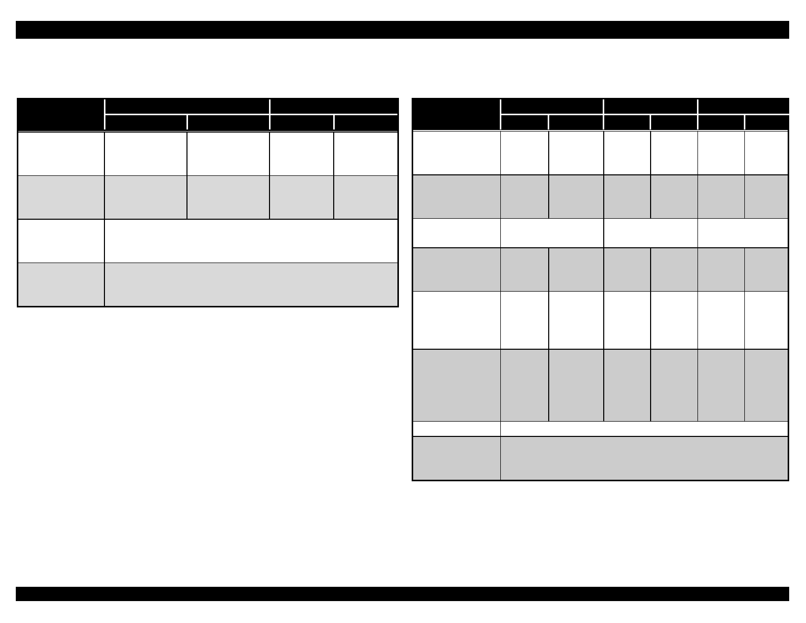
Table 1-8. Specifications for Single Sheets
Front Entry Rear Entry
Minimum Maximum Minimum Maximum
Width
(inches)
(mm)
3.9
100
16.5
420
3.9
100
16.5
420
Length
(inches)
(mm)
5.8
148
16.5
420
3.9
100
16.5
420
Thickness
(inches)
(mm)
0.0025
0.065
0.0055
0.14
0.0025
0.065
0.0055
0.14
Weight
(lb)
(g/m2)
14
52
24
90
14
52
24
90
Quality Plain or recycled paper;
not curled, folded, or
crumpled
Plain or recycled paper; not
curled, folded, or crumpled
Note: Use recycled paper only under normal temperature and humidity
conditions.
EPSON FX-2180 Service Manual Chapter 1 Product Description
1-6
Single-sheet multi-part forms
Table 1-9. Specifications for Single-sheet Multi-part Forms
Front Entry Rear Entry
Minimum Maximum Minimum Maximum
Width
(inches)
(mm)
3.9
100
16.5
420
3.9
100
16.5
420
Length
(inches)
(mm)
5.8
148
16.5
420
3.9
100
16.5
420
Copies 1 original + 5 copies 1 original + 5 copies
Total
thickness
(inches)
(mm)
0.0047
0.012
0.018
0.46
0.0047
0.012
0.018
0.46
Weight
(lb)
(g/m2)
12
40
15
58
12
40
15
58
Quality Plain or recycled paper; not
curled, folded, or crumpled
Plain or recycled paper; not
curled, folded, or crumpled
Binding A line of glue at the top or
on one side of the form
A line of glue at the top of
the form
Envelopes
Table 1-10. Specifications for Envelopes
Rear Entry
Minimum Maximum
No. 6 envelopes Width
(inches)
(mm)
6.5
165
Length
(inches)
(mm)
3.9
92
No. 10 envelopes Width
(inches)
(mm)
9.5
241
Length
(inches)
(mm)
4.1
105
Total thickness (inches)
(mm)
0.0063
0.16
0.020
0.52
Weight (lb)
(g/m2)
12
40
15
58
Quality Bond, plain, or airmail paper; not
curled, folded, or crumpled
Note:
Load envelopes using the rear (top) slot only; do not load envelopes in
the front slot.
Insert the envelope into the printer with the flap side on top and the
printable side down.
Before printing on envelopes, set the paper thickness lever to a
minimum of position 4 or 5 and turn on the card mode by pressing the
Tear Off/Bin button until both Tear Off/Bin lights are on. After you finish
printing on envelopes, press the Tear Off/Bin button once to exit the
card mode.
Use envelopes only under normal temperature and humidity conditions.
EPSON FX-2180 Service Manual Chapter 1 Product Description
1-7
Postcards
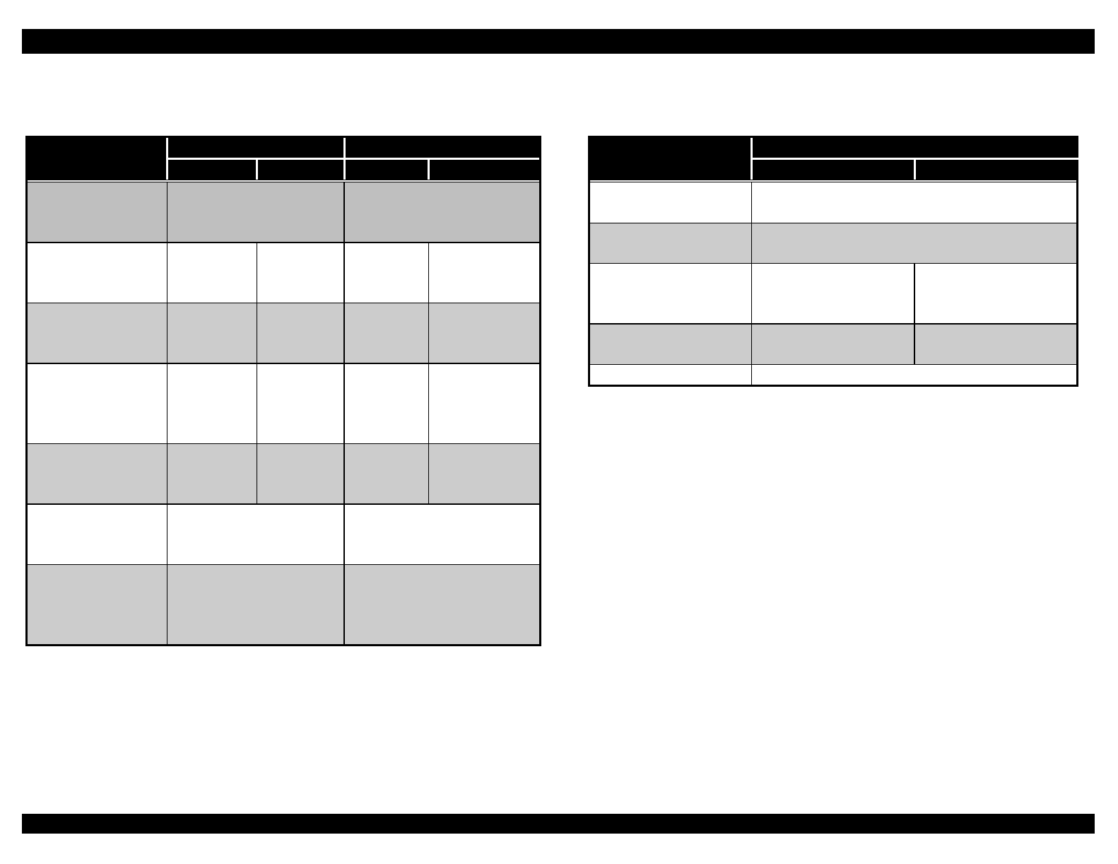
Table 1-11. Specifications for Postcards
Front Entry Rear Entry
Minimum Maximum Minimum Maximum
Width
(inches)
(mm)
3.9
100
5.83
148
3.9
100
5.83
148
Length
(inches)
(mm)
5.83
148
5.83
148
3.9
100
5.83
148
Thickness
(inches)
(mm)
0.0087
0.22
Weight
(lb)
(g/m2)
51
192
Note:
Before printing on postcards, set the paper thickness lever to position 3
or higher and turn on the card mode by pressing the Tear Off/Bin
button until both Tear Off/Bin lights are on. After you finish printing on
envelopes, press the Tear Off/Bin button once to exit the card mode.
Use postcards only under normal temperature and humidity conditions.
Continuous paper
Table 1-12. Specifications for Continuous Paper
Front Entry Rear Entry Bottom Entry
Min. Max. Min. Max. Min. Max.
Width
(inches)
(mm)
4
101.6
16
406.4
4
101.6
16
406.4
4
101.6
16
406.4
Length
(inches)
(mm)
4
101.6
22
558.8
4
101.6
22
558.8
4
101.6
22
558.8
Copies* 1 original + 5
copies
1 original + 5
copies
1 original + 5
copies
Total thickness
(inches)
(mm)
0.0025
0.065
0.018
0.046
0.0025
0.065
0.018
0.046
0.0025
0.065
0.018
0.046
Weight
(ordinary page)
(lb)
(g/m2)
12
52
22
82
12
52
22
82
12
52
22
82
Weight (one
sheet of a
multi-part form)
(lb)
(g/m2)
12
40
15
58
12
40
15
58
12
40
15
58
Quality Plain or recycled paper, carbonless multi-part forms
Binding Dots of glue or paper staples on both sides (front,
bottom, or rear entry) or dots of glue on only one side
(rear entry)
* To print 1 original + 6 copies, you must use the pull tractor along with
the front or rear tractor.
EPSON FX-2180 Service Manual Chapter 1 Product Description
1-8
Continuous paper with labels
Table 1-13. Specifications for Continuous Paper with Labels
Front Entry Bottom Entry
Minimum Maximum Minimum Maximum
Label size
(inches)
(mm)
15/16 × 2.5
23.8 × 63.5
15/16 × 2.5
23.8 × 63.5
Width
(inches)
(mm)
4
101.6
16
406.4
4
101.6
16
406.4
Length
(inches)
(mm)
4
101.6
22
558.8
4
101.6
22
558.8
Backing sheet
thickness
(inches)
(mm)
0.0028
0.07
0.0035
0.09
0.0028
0.07
0.0035
0.09
Total thickness
(lb)
(g/m2)
0.16
0.0063
0.19
0.0075
0.16
0.0063
0.19
0.0075
Label weight
(lb)
(g/m2)
17
68
17
68
Quality Avery continuous form
labels, Avery mini-line
labels, or equivalent
quality labels
Avery continuous form
labels, Avery mini-line
labels, or equivalent
quality labels
Note:
Use only continuous labels; do not use labels with single-sheet backing
paper.
Load continuous paper with labels only in the front or bottom slot; do not
load labels in the rear slot.
Roll paper
Table 1-14. Specifications for Roll Paper
Rear Entry
Minimum Maximum
Width (inches)
(mm)
8.5
216
Length (inches)
(mm)
Thickness
(inches)
(mm)
0.0028
0.07
0.0035
0.09
Weight (lb)
(g/m2)
14
52
22
82
Quality Plain paper; not curled, folded, or crumpled
1.1.7 Interface Specifications
Standard: Bidirectional parallel interface
(IEEE-1284 nibble mode supported)
Optional: Type B interface, level 2
1.1.8 Software Specifications
Control codes: ESC/P®
IBM® 2381 Plus emulation
Fonts: 1 draft bitmap and 2 LQ typefaces
8 barcode fonts
Character tables: Standard version: 11 tables
NLSP version: 20 tables
Input buffer: 64 KB

EPSON FX-2180 Service Manual Chapter 1 Product Description
1-9
1.1.9 Environmental Conditions
Temperature
Operating: 41° to 95° F (5° to 35° C)
When using recycled
paper, envelopes, labels,
or roll paper: 59° to 77° F (15° to 25° C)
Non-operating (storage): −22° to 140° F (−30° to 60° C)
Humidity
Operating: 10% to 80% RH
When using recycled
paper, envelopes, labels,
or roll paper: 30% to 60% RH
Non-operating (storage): 0% to 85% RH
1.1.10 Electrical Specifications
120 V model
Rated voltage: 120 VAC
Input voltage range: 99 to 132 VAC
Rated frequency range: 50 to 60 Hz
Input frequency range: 49.5 to 60.5 Hz
Rated current: 1.0 A (1.8 A maximum)
Power consumption: Approx. 46 W (ISO/IEC 10561 letter pattern)
Energy Star compliant
Insulation resistance: 10 MΩ minimum (between AC line and
chassis, 500 V)
Dielectric strength: 1000 VAC rms. 1 minute or 1200 VAC rms.
1 second (between AC line and chassis)
220 to 240 V model
Rated voltage: 220 to 240 VAC
Input voltage range: 198 to 264 VAC
Rated frequency range: 50 to 60 Hz
Input frequency range: 49.5 to 60.5 Hz
Rated current: 0.5 A (0.9 A maximum)
Power consumption: Approx. 46 W (ISO/IEC 10561 letter pattern)
Energy Star compliant
Insulation resistance: 10 MΩ minimum (between AC line and
chassis, 500 V)
Dielectric strength: 1500 VAC rms. 1 minute (between AC line
and chassis)
UPS (Universal Power Supply) model
Rated voltage: 100 to 120 VAC or 220 to 240 VAC
Input voltage range: 90 to 132 VAC or 198 to 264 VAC
Rated frequency range: 50 to 60 Hz
Input frequency range: 49.5 to 60.5 Hz
Rated current: 1.1 A (2.2 A maximum) or 0.6 A (1.1 A
maximum)
Power consumption: Approx. 46 W (ISO/IEC 10561 letter pattern)
Energy Star compliant
Insulation resistance: 10 MΩ minimum (between AC line and
chassis, 500 V)
Dielectric strength: 1500 VAC rms. 1 minute (between AC line
and chassis)
1.1.11 Physical Specifications
Dimensions: 25.16 in. (W) × 15.83 in. (D) × 10.12 in (H)
639 mm (W) × 402 mm (D) × 257 mm (H)
(with CSF bin 1): 25.16 in. (W) × 18.46 in. (D) × 14.96 in (H)
639 mm (W) × 469 mm (D) × 380 mm (H)
(with CSF bin 2): 25.16 in. (W) × 23.54 in. (D) × 16.18 in (H)
639 mm (W) × 598 mm (D) × 411 mm (H)
Weight: Approx. 28.66 lb (13 kg)
(with CSF bin 1): Approx. 35.94 lb (16.3 kg)
(with CSF bin 2): Approx. 37.92 lb (17.2 kg)
1.1.12 Reliability
Total print volume: 7.5 million lines (except print head)
MTBF: 10,000 power-on hours (POH)
Print head life: Approx. 300 million characters
EPSON FX-2180 Service Manual Chapter 1 Product Description
1-10
1.1.13 Safety Approvals
120 V model
Safety standards: UL1950
CSA C22.2 No. 950
EMI: FCC part 15 subpart B class B
CSA C108.8 class B
220 to 240 V model
Safety standards: EN 60950 (TÜV, NEMKO)
EMI: EN 55022 (CISPR pub. 22) class B
AS/NZS 3548 class B
UPS model
Safety standards: UL1950
CSA C22.2 No. 950
EN 60950 (TÜV, NEMKO)
EMI: FCC part 15 subpart B class B
CSA C108.8 class B
EN 55022 (CISPR pub. 22) class B
AS/NZS 3548 class B
1.1.14 CE Marking
220 to 240 V and UPS models
Low Voltage Directive 73/23/EEC: EN60950
EMC Directive 89/336/EEC: EN55022 class B
EN61000-3-2
EN61000-3-3
EN50082-1
IEC801-2
IEC801-3
IEC801-4
1.1.15 Acoustic Noise
Level: Approx. 55 dB(A), according to ISO 7779
pattern
1.1.16 Ribbon Cartridge
Type: Fabric
Color: Black
Ribbon life: Approx. 12 million characters
(draft, 10 cpi, 14 dots/character)
1.2 Operation
This section provides detailed information about the control panel buttons
and LEDs, and explains the printer’s beep patterns.
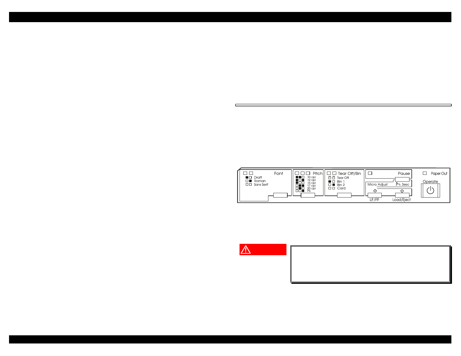
1.2.1 Control Panel
The control panel contains seven non-locking pushbuttons and nine LEDs,
as shown below.
Figure 1-7. Control Panel
1.2.1.1 Buttons
WARNING
The power switch is wired in the secondary
circuitry of the power supply board. Therefore, the
power supply’s primary circuitry remains live
even after the printer is turned off.
EPSON FX-2180 Service Manual Chapter 1 Product Description
1-11
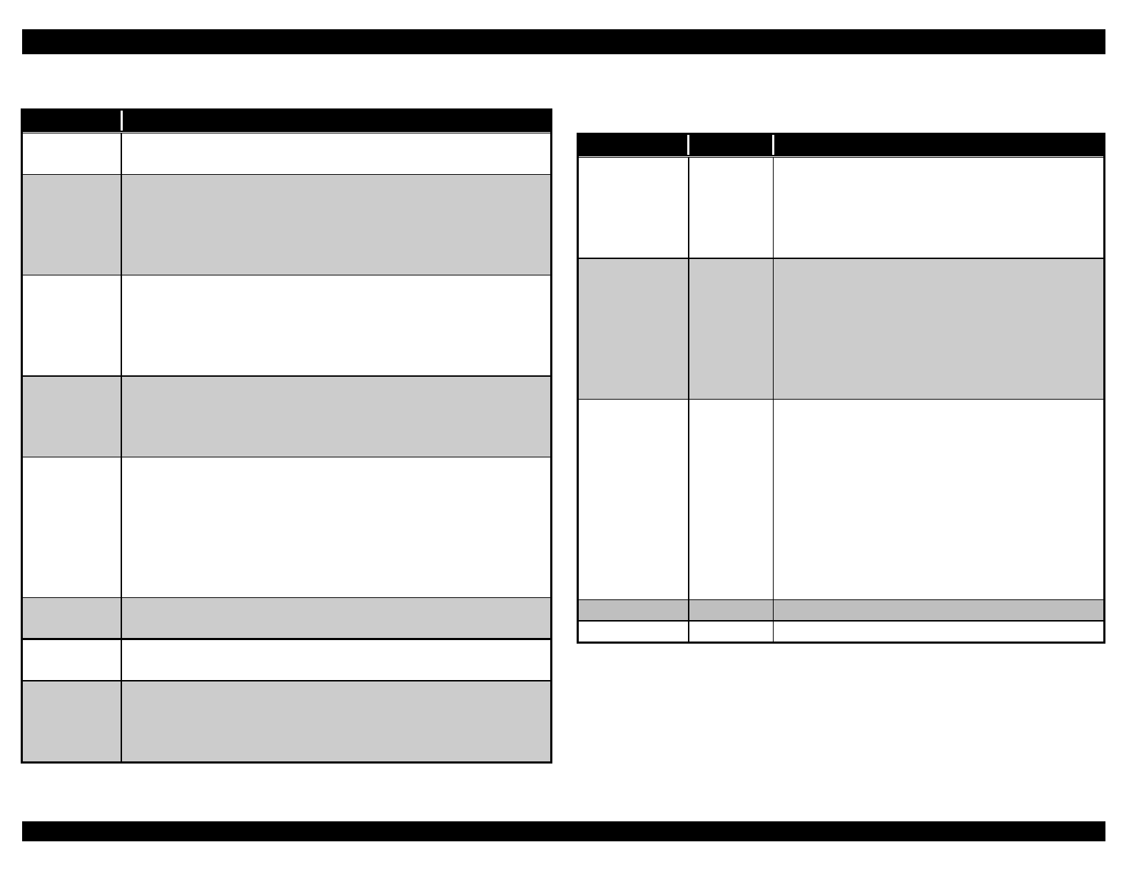
Table 1-15. Button Functions
Button Function
Operate Turns the printer on and off. The printer is off when the top
of this button is even with the button protectors.
Pause • Stops printing temporarily, and resumes printing when
pressed again. (Selects on line or off line status.)
• When held down for three seconds when the printer is in
the standby state, enters the micro adjust mode. When
pressed again, exits the micro adjust mode.
Load/Eject • Loads continuous paper from the standby position.
• Feeds continuous paper backward to the standby
position.
• Loads a single sheet of paper from the paper entry slot.
• Ejects a single sheet of paper if a sheet is loaded.
LF/FF • When pressed, executes a line feed.
• When held down, executes a form feed. This advances
continuous paper to the next top-of-form position or
ejects a single sheet.
Tear
Off/Bin
• Feeds continuous paper forward to the tear-off position.
• Feeds continuous paper backward from the tear-off
position to the top-of-form position.
• Selects a cut-sheet feeder bin when the cut-sheet feeder
is installed.
• Enters the card mode to print on postcards and
envelopes.
Font Selects one of the following fonts: Draft, Roman, or Sans
Serif.
Pitch Selects one of the following font widths: 10 cpi,
12 cpi, 15 cpi, 17 cpi, 20 cpi, or PS (proportional spacing).
Micro
Adjust ↑ / ↓In the micro adjust mode, executes a micro feed (moves
the paper forward or backward 1/216 inch). Depending on
the position of your paper, you can use this button to adjust
the top-of-form or tear-off position.
1.2.1.2 LEDs
Table 1-16. LED Indicators
LED(s) Color Description
Pause Orange • On when the printer is paused.
• Off when the printer is on line.
• Flashes when the printer is in the micro
adjust mode or the print head is
overheated.
Paper Out Red • On when no paper is loaded or paper is
not loaded correctly in the selected paper
source.
• Off when paper is loaded correctly in the
selected paper source.
• Flashes when paper has not been fully
ejected or a paper jam has occurred.
Tear Off/Bin Green • o o when continuous paper is not in the
tear-off position.
• f f when continuous paper is in the tear-
off position.
• o n when bin 1 of the optional cut-sheet
feeder is selected.
• n o when bin 2 of the optional cut-sheet
feeder is selected.
• n n when the printer is in the card mode.
n = on o = off f = flashing
Font Green Indicates which font is selected.
Pitch Green Indicates which font size is selected.
EPSON FX-2180 Service Manual Chapter 1 Product Description
1-12
1.2.1.3 Beeper
The printer beeps during the error conditions described in Table 1-17.
Table 1-17. Error Conditions
Error Beep Pattern
Paper out ❍ ❍ ❍
Cover open ❍ ❍ ❍
Paper release lever operation ❍ ❍ ❍ ❍ ❍
Illegal panel operation ❍
❍ indicates the beeper sounds for approximately 100 ms with an interval of
approximately 100 ms.
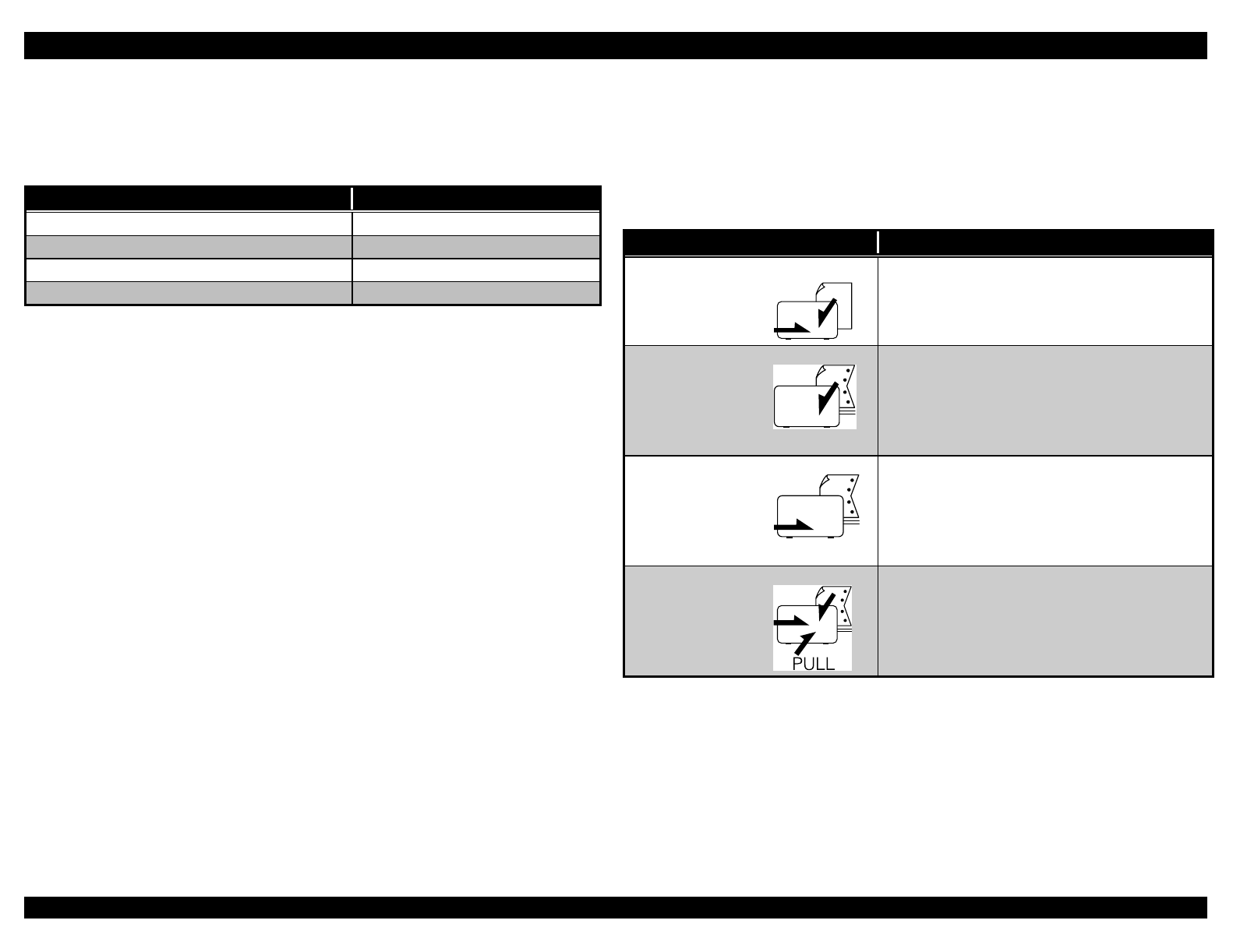
1.2.2 Paper Release Lever Positions
Use the paper release lever to select which paper path you want the printer
to load paper from. The table below shows the corresponding paper path(s)
for each paper release lever position.
Table 1-18. Paper Release Lever Positions
Lever Position Description
Single-sheet For loading single sheets from the top or
front slot.
Rear push tractor For loading continuous paper from the
tractor installed in the rear push position.
Also set the lever to this position when
using the rear push and pull tractors in
combination.
Front push tractor For loading continuous paper from the
tractor installed in the front push position.
Also set the lever to this position when
using the front push and pull tractors in
combination.
Pull tractor For loading continuous paper from the
tractor installed on top of the printer in the
pull position.
EPSON FX-2180 Service Manual Chapter 1 Product Description
1-13
1.2.3 Paper Thickness Lever Positions
You need to set the paper thickness lever for the type of paper you are
using, as shown in the table below.
Table 1-19. Paper Thickness Lever Positions
Paper Type Lever Position
Ordinary paper (single sheets or continuous paper) 0
Carbonless multi-part forms with:
2 parts (original + 1 copy)
3 parts (original + 2 copies)
4 parts (original + 3 copies)
5 parts (original + 4 copies)
6 parts (original + 5 copies)
7 parts (original + 6 copies)
1
3
4
5
6
6
Thin paper -1 or 0
Continuous paper with labels 2
Envelopes 4 or 5
Postcards 3
1.3 Special Functions
You can access the printer’s special functions by holding down the button
indicated while turning on the printer.
1.3.1 Printing a Self Test
To perform a self test, follow these steps:
1. Make sure paper is loaded and the printer is turned off.
2. To run the test using the draft font, hold down the LF/FF button while
you press the Operate button to turn on the printer. To run the test
using the printer’s near letter-quality fonts, hold down the Load/Eject
button while you turn on the printer.
After a few seconds, the printer loads the paper automatically and
begins printing the self test. A series of characters is printed.
3. To end the self test, press the Pause button to stop printing. If a printed
page remains in the printer, press the Load/Eject button to eject it.
Then turn off the printer.
1.3.2 Turning on the Double-strike Mode
If the printing on the bottom copies of your thick multi-part forms is faint,
turn on the double-strike mode as described below. In the double-strike
mode, the printer prints draft and bitmap images using double-strike
printing. The printer does not use two-pass printing in this mode.
Note:
The double-strike mode is available only when the paper thickness lever
is set to position 4 or higher and the paper release lever is set to the pull
tractor position.
Always turn on the double-strike mode before printing on multi-part
forms with seven parts.
Use double-strike mode only under normal temperature and humidity
conditions.
When the printer is in the double-strike mode, the print speed is
reduced.
1. Load your multi-part forms on the pull tractor.
2. Make sure the printer is turned off.
3. While holding down the Font button, press the Operate button to turn
on the printer. The printer beeps twice to indicate double-strike mode is
on.
To exit the double-strike mode, turn off the printer, then hold down the Font
button and press the Operate button to turn the printer back on. The printer
beeps once to indicate double-strike mode is off.
EPSON FX-2180 Service Manual Chapter 1 Product Description
1-14
1.3.3 Using the Bidirectional Adjustment Mode
If the vertical lines in the printout are not properly aligned, you can use the
printer’s bidirectional adjustment mode to correct this problem. See
Chapter 5 for instructions on performing the bidirectional adjustment.
1.3.4 Changing Default Settings
You can change the printer’s default settings using the default-setting
mode. To enter the default-setting mode, hold down the Pitch button and
press the Operate button to turn on the printer. The printer prints the
language selection instructions. Select the language you want, and then
press the Font button to print the default-setting mode instructions. The
printed instructions list the settings you can change, describe how to
change them, and show you how the control panel lights help you make
settings.
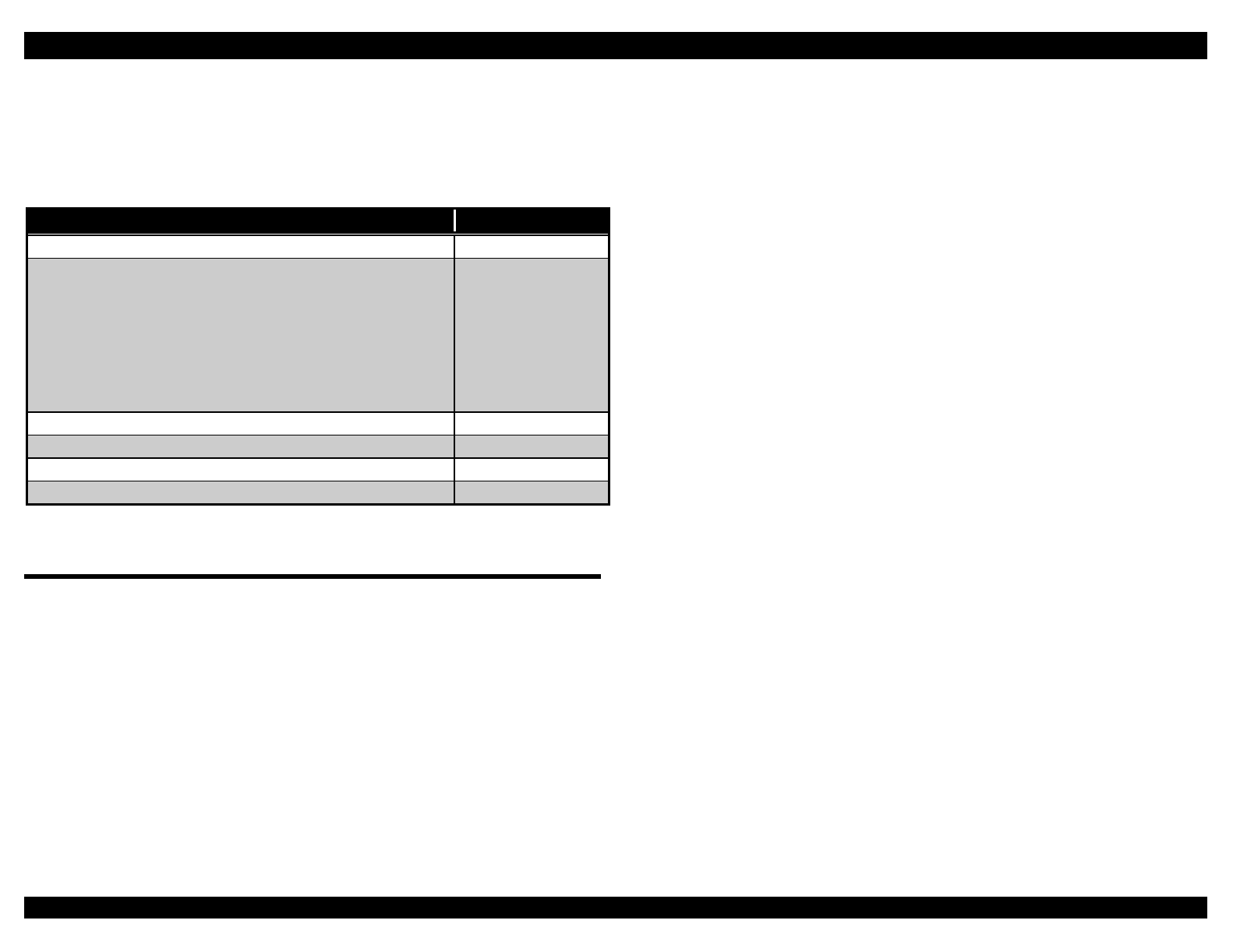
Table 1-20 summarizes the default settings and options. Factory settings
are bold.
Table 1-20. Default Settings
Setting Options
Page length for front tractor* Length in inches: 3, 3.5, 4, 5.5, 6, 7, 8,
8.5, 11, 70/6, 12, 14, 17
Page length for rear tractor* Length in inches: 3, 3.5, 4, 5.5, 6, 7, 8,
8.5, 11, 70/6, 12, 14, 17
Skip over perforation Off, On
Auto tear-off Off, On
Auto line feed Off, On
Print direction Bi-D, Uni-D
I/F (interface) mode Auto, Parallel, Optional
Auto I/F (interface) wait time 10 seconds, 30 seconds
Software ESC/P, IBM 2381 Plus
0 slash Off, On
High speed draft Off, On
Input buffer Off, On
Buzzer Off, On
Auto CR (IBM 2381 Plus)** Off, On
IBM character table** Table 2, Table1
Character table Standard model: Italic, PC 437, PC
850, PC 860, PC 863, PC 865, PC
861, BRASCII, Abicomp, Roman 8,
ISO Latin 1
International character set for
Italic table
Italic U.S.A., Italic France, Italic
Germany, Italic U.K., Italic Denmark 1,
Italic Sweden, Italic Italy, Italic Spain 1
* The options available vary depending on the country.
** These settings take effect only when IBM 2381 Plus emulation is
selected.
EPSON FX-2180 Service Manual Chapter 1 Product Description
1-15
1.3.5 Printing a Hex Dump
You can print a hexadecimal dump to isolate communication problems
between the printer and a software program. To enter hex dump mode,
hold down both the LF/FF and Load/Eject buttons while you press the
Operate button to turn on the printer. Then open a software program and
send a print job to the printer.
Your printer prints all the codes it receives in hexadecimal format. If
characters are printable, they appear in the right column as ASCII
characters. Nonprintable codes, such as control codes, are represented by
dots.
To exit hex dump mode, press the Pause button to stop printing and the
Load/Eject button to eject the printed page. Then turn off the printer.
1.3.6 Clearing the EEPROM
To clear the EEPROM, hold down the Font and Tear Off/ Bin buttons
while you press the Operate button to turn on the printer. The settings in
EEPROM area 1 are reset to the factory defaults, with the exception of the
counters that provide the following information:
Total lines printed since production
Total power-on hours (in minutes)
Total lines printed since a new ribbon cartridge was installed
Starting year, month, and date. This is the date of printer production,
and helps you determine if it is better for the user to repair or replace the
printer.
See the FX-2180 specifications for more information.
CAUTION
The printer stores the values for the total lines
printed since production, total power-on hours,
total lines printed since ribbon cartridge
replacement, and starting year, month, and date in
the EEPROM on the main board.
1.3.6.1 Clearing the Ribbon Cartridge Replacement Counter
To reset the EEPROM’s ribbon cartridge replacement counter to zero, hold
down the LF/FF and Tear Off/Bin buttons while you press the Operate
button to turn on the printer.
1.4 Consumables and Options
1.4.1 Consumables
Ribbon cartridge: S015086
Ribbon pack: S010033
1.4.2 Options
Paper Handling Options
High-capacity cut-sheet feeder (bin 1): C806731
Second-bin cut-sheet feeder (bin 2): C806741
Pull tractor: C800321
Roll paper holder: #8310
Optional Interface Cards
Serial I/F card: C823051
32KB intelligent serial I/F card: C823071
Coax I/F card: C823141
Twinax I/F card: C823151
Type B IEEE-1284 bidirectional parallel I/F card: C823452
Multi-protocol Ethernet print server I/F card: C823572

OPERATING PRINCIPLES
&+$37(5
EPSON FX-2180 Service Manual Chapter 2 Operating Principles
2-1
2.1 Overview
The printer’s main components include the printer mechanism, power
supply circuit, control circuit, control panel, and housing. This chapter
describes the operating principles of the main components.
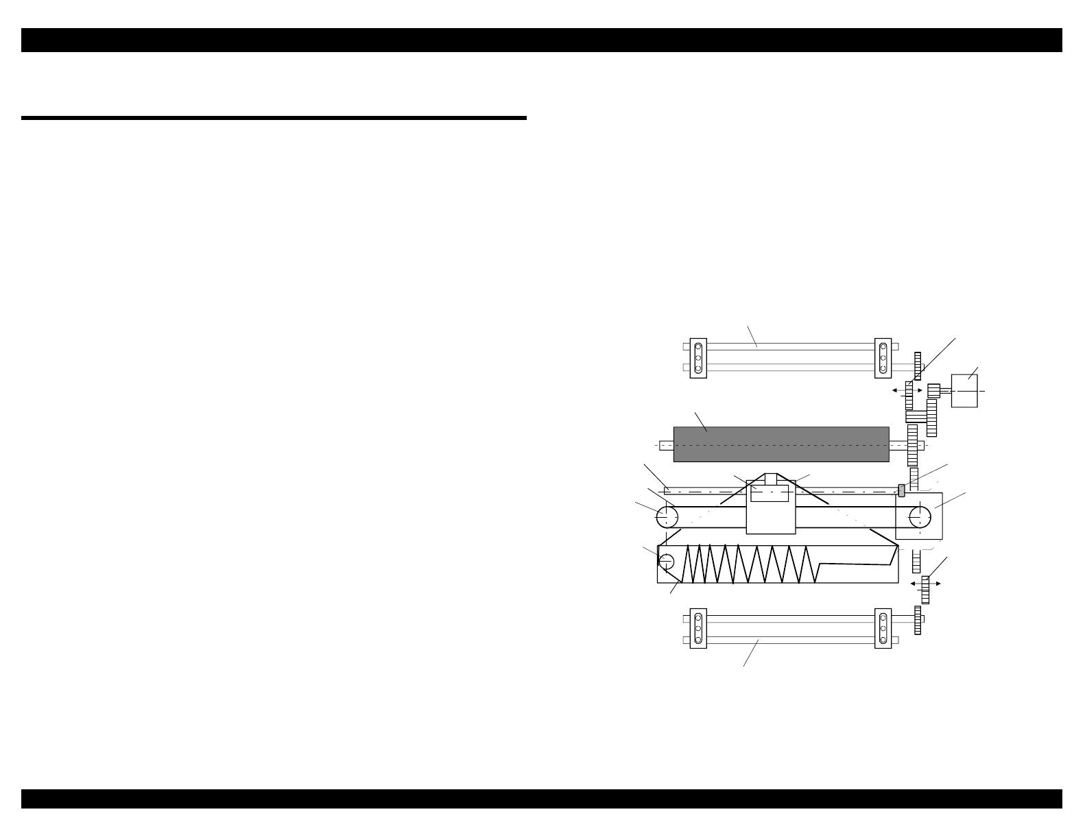
2.1.1 Printer Mechanism
The printer mechanism consists of the following parts:
Print head
The print head prints dots on paper using the ink ribbon. Print data
comes from the control circuit.
Carriage mechanism
The main parts of the carriage mechanism are the carriage unit,
carriage (CR) motor, timing belt, driven pulley, and CR guide shaft. The
carriage unit contains the print head. The carriage mechanism moves
the carriage unit along the CR guide shaft between the left and right
ends of the printable area.
Platen gap mechanism
The platen gap is the gap between the platen and the print head. You
adjust the platen gap to maintain print quality when using paper of
different weights or thicknesses. The platen gap mechanism consists of
the CR guide shaft, the platen gap adjustment bushing, and the platen
gap (PG) adjustment lever. The platen gap mechanism moves the print
head toward or away from the platen, depending on the position of the
PG adjustment lever.
Paper feed mechanism
The main components of the paper feed mechanism are the paper feed
(PF) motor, the rear or front tractor, and the platen. Using the PF
motor, the paper feed mechanism picks up continuous or single-sheet
paper, moves it to the print head for printing, and ejects it from the
printer after the page has been printed.
Disengage mechanism
The disengage mechanism consists of two disengage gears. It
switches the paper feed torque from the PF motor to the tractor(s) or
the paper feed rollers depending on the selected paper feed method
(friction, front push tractor, rear push tractor, pull tractor, or push-pull
tractor feeding).
Ribbon advance mechanism
The main components of the ribbon advance mechanism are the ribbon
feed roller and the driven pulley. The ribbon advance mechanism winds
the ink ribbon in one direction. This allows the printer to use a fresh
ribbon surface for printing.
rear tractor
front tractor
platen
print head
PF motor
CR motor
disengage gear 1
disengage gear 2
ink ribbon
CR guide shaft
carriage unit
timing belt
ribbon feed roller
driven pulley
PG adjustment bushing
Figure 2-1. Printer Mechanism
EPSON FX-2180 Service Manual Chapter 2 Operating Principles
2-2
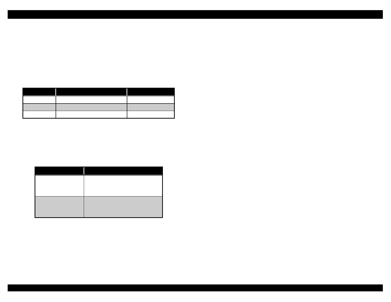
2.1.2 Power Supply Circuit
The printer can be powered by one of the following three power supply
boards: C166 PSB (120 V), C166 PSE (220 – 240 V), or C244 PSH
(120 V / 220 – 240 V). The boards function in the same way, except each
board has a different primary circuit. The table below lists the input
voltages and fuse ratings of the boards.
Table 2-1. Power Supply Board
Board Input Voltage Fuse F1 Rating
C166 PSB 103.5 – 132 V 3.15 A / 125 V
C166 PSE 198 – 264 V T 2.0 AH / 250 V
C244 PSH 85 – 138 V / 187 – 276 V 5HT4
2.1.2.1 Power Supply Circuit Operation
The power supply board has two DC power outputs: one for the control
circuit and one for the printer mechanism. The table below lists the
applications of the output voltages.
Table 2-2. Power Supply Output Applications
Output Voltage Applications
+5 VDC • Control circuit board logic
• Sensors
• Control panel LEDs
+35 VDC • CR motor
• PF motor
• Print head
When AC power enters the printer from an external power source, the filter
circuit removes the noise. Then the AC voltage undergoes full-wave
rectification and is smoothed to produce direct voltage. In the C244 PSH
board, the AC voltages undergo voltage doubler rectification in the
automatic switching IC and are smoothed to produce direct voltage. The
voltage is fed to the gate port for switching FET Q1 through resistors R18
and R31. Then the switching circuit operates.
The secondary smoothing circuit produces a stepped down +35 VDC
voltage. The +5 VDC voltage is generated and stabilized by feeding the
+35 VDC voltage through the +5 VDC power supply circuit. The power
supply circuit includes a ZC-RCC (zero cross-ringing choke converter),
which contributes to the power supply circuit’s high stability, efficiency, and
portability.
The secondary circuit system of the power supply circuit includes the
Operate (power) button. The Operate button is located on the printer’s
control panel and controls the power supply circuit.
A +35 V line constant voltage control circuit and over-current/over-voltage
protection circuits are provided to protect the printer and control circuits.
EPSON FX-2180 Service Manual Chapter 2 Operating Principles
2-3
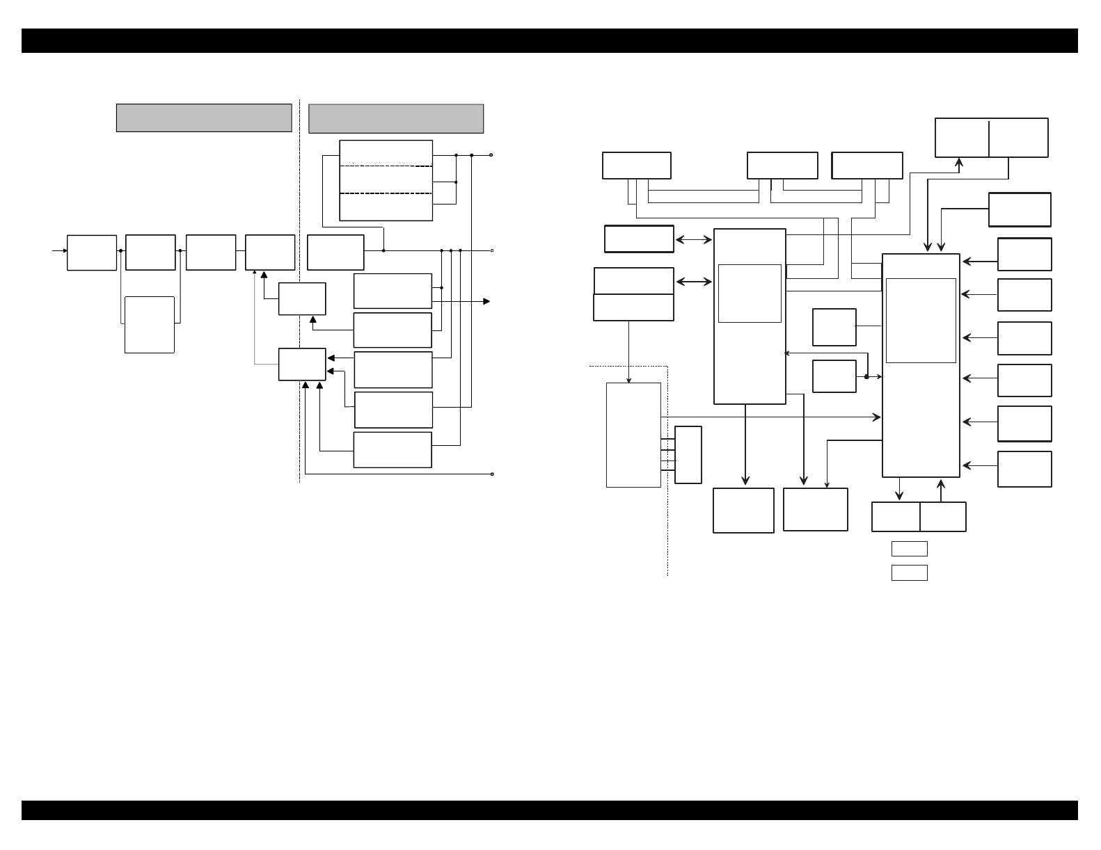
The figure below shows the power supply circuit block diagram.
filter circuit full-wave
rectification
circuit
smoothing
circuit switching
circuit
AC input
smoothing
circuit
+5 V switching
regulator
+5 V over-current
protection circuit
+35 VDC
+5 VDC
photo-
coupler
photo-
coupler +35 V line
over-voltage
protection circuit
+35 V line
overload
detector circuit
+35 V line
over-current
protection circuit Operate
(power) button
secondary circuit
CPU
port 20
+35 V line
constant voltage
control circuit
+5 V line
over-voltage
protection circuit
+5 V constant voltage
control circuit
voltage
doubler
rectification
automatic
switching
circuit
C244 PSH only
primary circuit
Figure 2-2. Power Supply Circuit Block Diagram
2.1.3 Control Circuit
The printer’s control circuit consists of the C244 MAIN control board and
the control panel board.
2.1.3.1 Control Circuit Operation
The control circuit includes a TMP96C141BF CPU that runs at 17.20 MHz,
an E05B50** gate array, a 2 Mbit PROM (or 2 Mbit / 4 Mbit flash ROM), a 1
Mbit / 4 Mbit PS-RAM (or SRAM), a serial (or parallel) EEPROM, and other
circuits. The control circuit controls all the printer’s components. Figure 2-3
shows the control circuit block diagram.
gate array
CPU
CSF driver CSF
sensor
rear PE
sensor
front PE
sensor
TOP
sensor
home
position
sensor
paper
release
lever sensor
platen gap
lever
sensor
+35 V voltage
sensor
print head
driver
print head
temperature
sensor
EPROM PS-RAM
or SRAM
serial
EEPROM
reset IC
PF driver CR driver
control panel
buttons & LEDs
Operate button
parallel I/F
type B I/F
5 V
GL
35 V
GP
IC2
IC1
E05B50**
TMP96C141BF
Q2-Q19
IC12
SLA7024M
UDN2917EB
IC8
IC15
: data bus
: address bus
IC3
IC5
PSC
PWDN
power supply
board
IC9
Figure 2-3. Control Circuit Block Diagram

EPSON FX-2180 Service Manual Chapter 2 Operating Principles
2-4
The table below identifies and describes the main components of the
control circuit on the C244 MAIN board.
Table 2-3. Main Components of the Control Circuit
Component IC Function(s)
Gate array
(E05B50**)
IC1 • System control
• Peripheral device control
CPU
(TMP96C141BF)
IC2 • Receives data from the host
computer and sends it to the input
buffer in RAM
• Extends the input data held in the
buffer to create image data
• Loads image data to the image data
buffer
• Transfers image data to the print
head
1 Mbit / 4 Mbit
PS-RAM
IC3 Contains the buffer and the working
area
2 Mbit PROM IC5 Contains the character tables and the
program that runs the CPU
Serial EEPROM
(AT93C46)
IC8 Contains data including:
• Default setting values
• Market data
• Mechanism and print head
parameters
SLA7024M IC9 Driver circuit for the CR motor
A2917SEB IC12 Driver circuit for the PF motor
Reset IC
(BH6150F)
IC15 Generates the reset signal at power on
and power down, and resets the CPU
and the gate array

TROUBLESHOOTING
EPSON FX-2180 Service Manual Chapter 3 Troubleshooting
3-1
3.1 Overview
This chapter contains flowcharts and checkpoint tables for
troubleshooting the printer. The flowcharts tell you which printer unit or
part to replace based on the printer’s symptoms. The checkpoint tables
list the correct values and ranges for printer part characteristics, such as
resistance and continuity. You can compare the characteristics of a printer
part to the checkpoint values to identify defective parts.
3.2 Troubleshooting Information
This section describes how to determine whether various printer units or
parts are defective.
3.2.1 Print Head
To determine whether a print head is defective, measure the print head’s
coil resistance as described in the table below. Then compare the coil
resistances with the correct meter reading in the table.
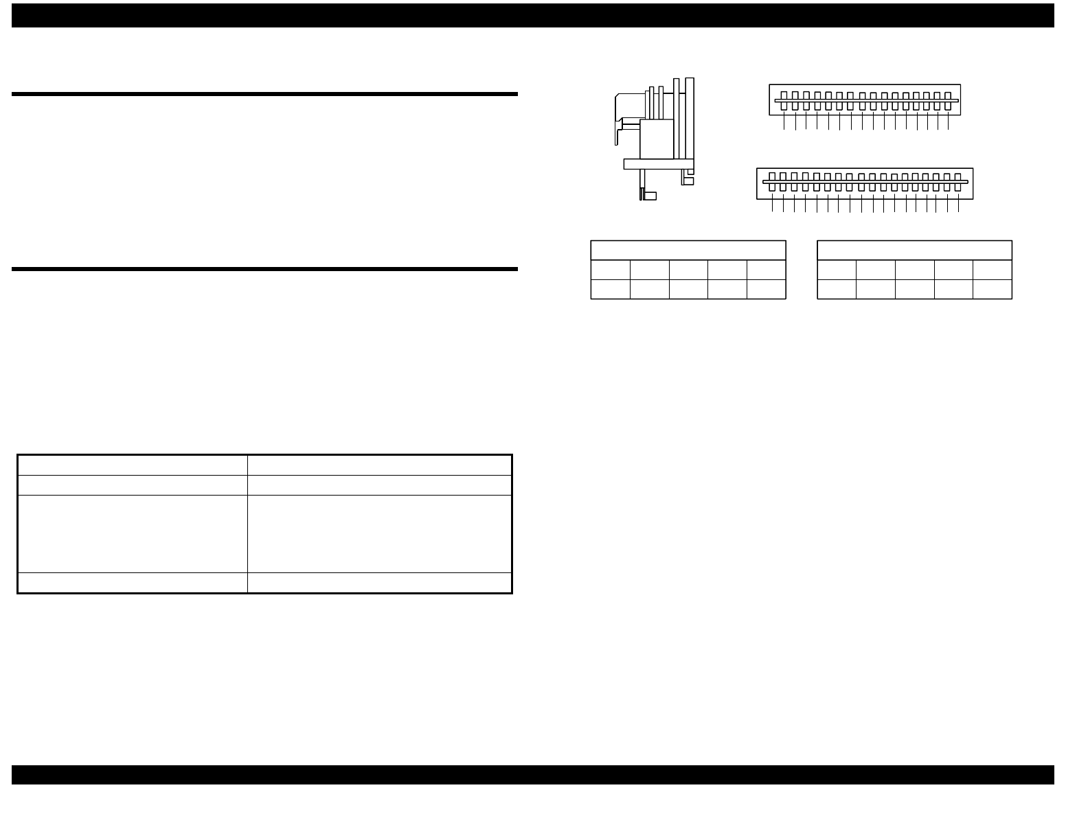
Table 3-1. Print Head Coil Resistance Test Points
Common pin numbers See Figure 3-1
Test pin numbers See Figure 3-1
Test method Turn off the printer and disconnect the
print head. Set the meter to ohms, and
place one lead on each pin and the other
lead on each common pin.
Meter reading 16.4 Ω ± 10% at 77° F (25° C)
315 C5 2 C6 5 16 11 C7 17 C8 14 4 8
1913 7C1 18 C2 12 C3 C4 610TT
XX X
X
XX
R
F
R
F
F
COM. C1 C2 C3 C4
1, 7, 13 9 10, 18 6, 12
R
COM. C5 C6 C7 C8
2, 5, 11 3, 15 16, 17 4, 8, 14
Pin No. Pin No.
T: Thermistor terminal
X: Not used
Figure 3-1. Print Head Connector Pin Alignment
EPSON FX-2180 Service Manual Chapter 3 Troubleshooting
3-2
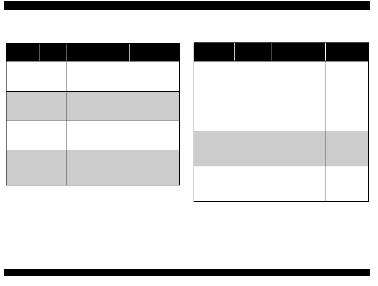
3.2.2 Sensors
Table 3-2. Sensor Test Points
Sensor
Connector
Test Pin
Numbers
Test Method
(Set the meter to DC
voltage.)
Meter Reading
CN4
(HP sensor)
1: HP
2: GND
3: +5 V
Place one lead on pin 1 and
the other lead on pin 2.
Check the resistances while
blocking the two sensor
terminals.
• Open: +5 V
(home position)
• Short: 0 V
(not in home
position)
CN5
(rear PE
sensor)
1: +5 V
2: PE
3: GND
Place one lead on pin 2 and
the other lead on pin 3.
Check the resistances while
toggling the rear PE sensor
lever.
• Open: +5 V
(Paper is loaded.)
• Short: 0 V
(No paper is
loaded.)
CN6
(front PE
sensor)
1: PE
2: GND
Place one lead on pin 1 and
the other lead on pin 2.
Check the resistances while
toggling the front PE sensor
lever.
• Open: +5 V
(Paper is loaded.)
• Short: 0 V
(No paper is
loaded.)
CN7
(TOP sensor)
1: E
2: GND
3: +5 V
4: A
Place one lead on pin 2 and
the other lead on pin 3.
Check the resistances while
inserting and removing paper
between the platen and the
sensor.
• Open: 0 V
(No paper is
loaded.)
• Short: +5 V
(Paper is loaded.)
Table 3-2. Sensor Test Points (Continued)
Sensor
Connector
Test Pin
Numbers
Test Method
(Set the meter to DC
voltage.)
Meter Reading
CN12
(paper release
sensors 1 and 2)
1: Release 1
2: GND
3: Release 2
4: GND
1. Place one lead on
pin 1 and the other
lead on pin 2. Check
the resistances
while toggling the
paper release lever.
2. Place one lead on
pin 3 and the other
lead on pin 4. Check
the resistances
while toggling the
paper release lever.
• Open: +5 V
• Short: 0 V
CN13
(PG sensors 1
and 2)
1: PG 1
2: GND
3: PG 2
4: GND
Place one lead on pin 1
and the other lead on
pin 2. Check the
resistances while
toggling the PG sensor
lever.
• Open: +5 V
• Short: 0 V
CN2 on the
control panel
board
(cover open
sensor)
1: COPEN
2: GND
Place one lead on pin 2
and the other lead on
pin 3. Check the
resistances while
toggling the cover open
sensor lever.
• Open: +5 V
(The cover is
open.)
• Short: 0 V
(The cover is
closed.)
EPSON FX-2180 Service Manual Chapter 3 Troubleshooting
3-3
3.2.3 Motors
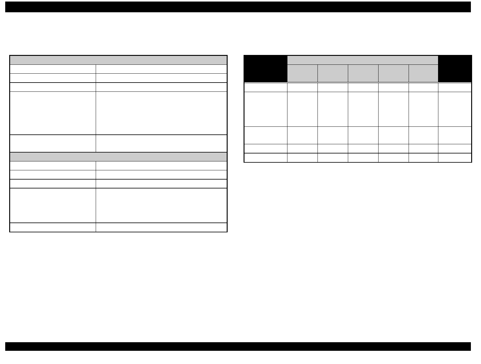
Table 3-3. Motor Test Points
PF Motor
Motor connector CN10
Common pin number
Test pin numbers 1, 2, 3, and 4
Test method Turn off the printer and disconnect the PF
motor from the control board. Set the meter to
ohms, and place one lead on pin 1 and the
other lead on pin 3. Then place one lead on
pin 2 and the other lead on pin 4.
Meter reading 16.1 Ω ± 10% per phase at 77° F
(25° C)
CR Motor
Motor connector CN11
Common pin number 5
Test pin numbers 1, 2, 3, and 4
Test method Turn off the printer and disconnect the CR
motor from the control board. Set the meter to
ohms, and place one lead on pin 5 and the
other lead on each of the four test pins.
Meter reading 2.7 Ω ± 10% per phase at 77° F (25° C)
3.2.4 Error Conditions
Table 3-4. Error Conditions
LightsError
Pause Paper
Out
Tear
Off/Bin
Pitch Font
Beep
Pattern
Paper out On On ❍ × 3
Paper jam
(The paper is
not ejected
completely.)
On Flashes ❍ × 3
Print head
overheated
Flashes
Cover open On ❍ × 3
Fatal error Flashes Flashes Flashes Flashes Flashes ● × 5
❍Indicates the beeper sounds for approximately 100 ms with an interval
of approximately 100 ms.
●Indicates the beeper sounds for approximately 500 ms with an interval
of approximately 100 ms.
EPSON FX-2180 Service Manual Chapter 3 Troubleshooting
3-4
3.3 Unit Level Troubleshooting
You may be able to identify a defective printer unit simply by observing
the printer’s symptoms. The table below lists the symptoms for several
printer problems. After you determine the type of printer problem you
have, see the corresponding flowchart to isolate the cause of the problem
and repair the printer.
Table 3-5. Printer Symptoms and Problem Descriptions
Symptom Problem Description Flowchart
Abnormal
carriage
operation
• The carriage does not move at all.
• When you turn on the printer, the carriage
moves away from the home position and then
stops. All the indicator LEDs on the control
panel flash.
Flowchart 1
Abnormal
paper
feeding
• The printer does not feed the paper at all.
• When you turn on the printer, the printer ejects
the paper automatically.
• After you load paper, the printer ejects the
paper automatically and then indicates it is in
the ready state.
Flowcharts
2-1 and 2-2
Abnormal
power
operation
• The control panel indicator LEDs do not
come on.
• The Operate button does not work.
• The control panel buttons do not work.
Flowchart 3
Abnormal
printing
• No image is printed.
• Printing is faulty; some dots are not printed.
Flowchart 4
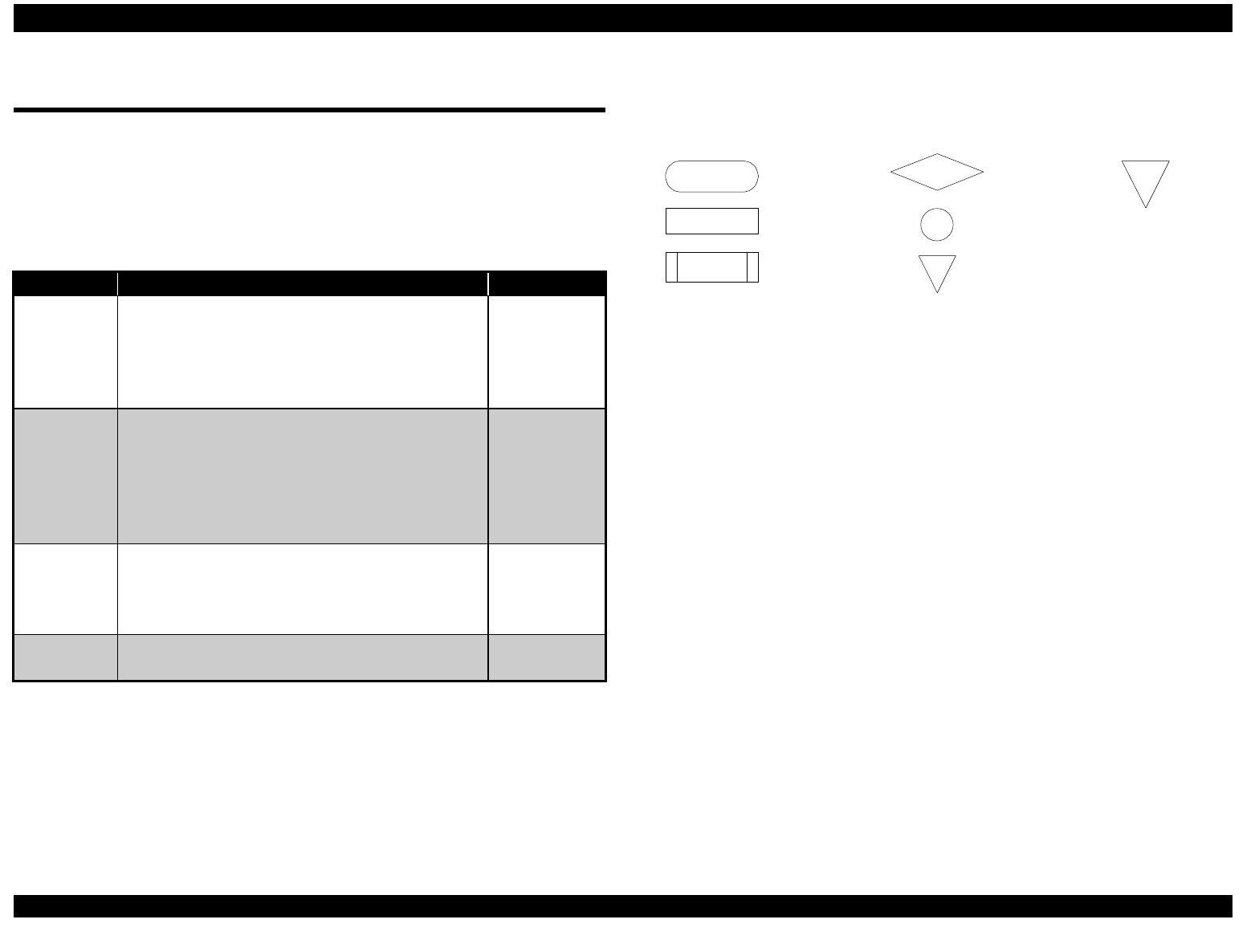
The flowcharts use the following symbols:
START Start
Instructions
Refer to the
specified flowchart
Decision
Branching
END
Return to the start
of the flowchart
END
Figure 3-2. Flowchart Symbols
EPSON FX-2180 Service Manual Chapter 3 Troubleshooting
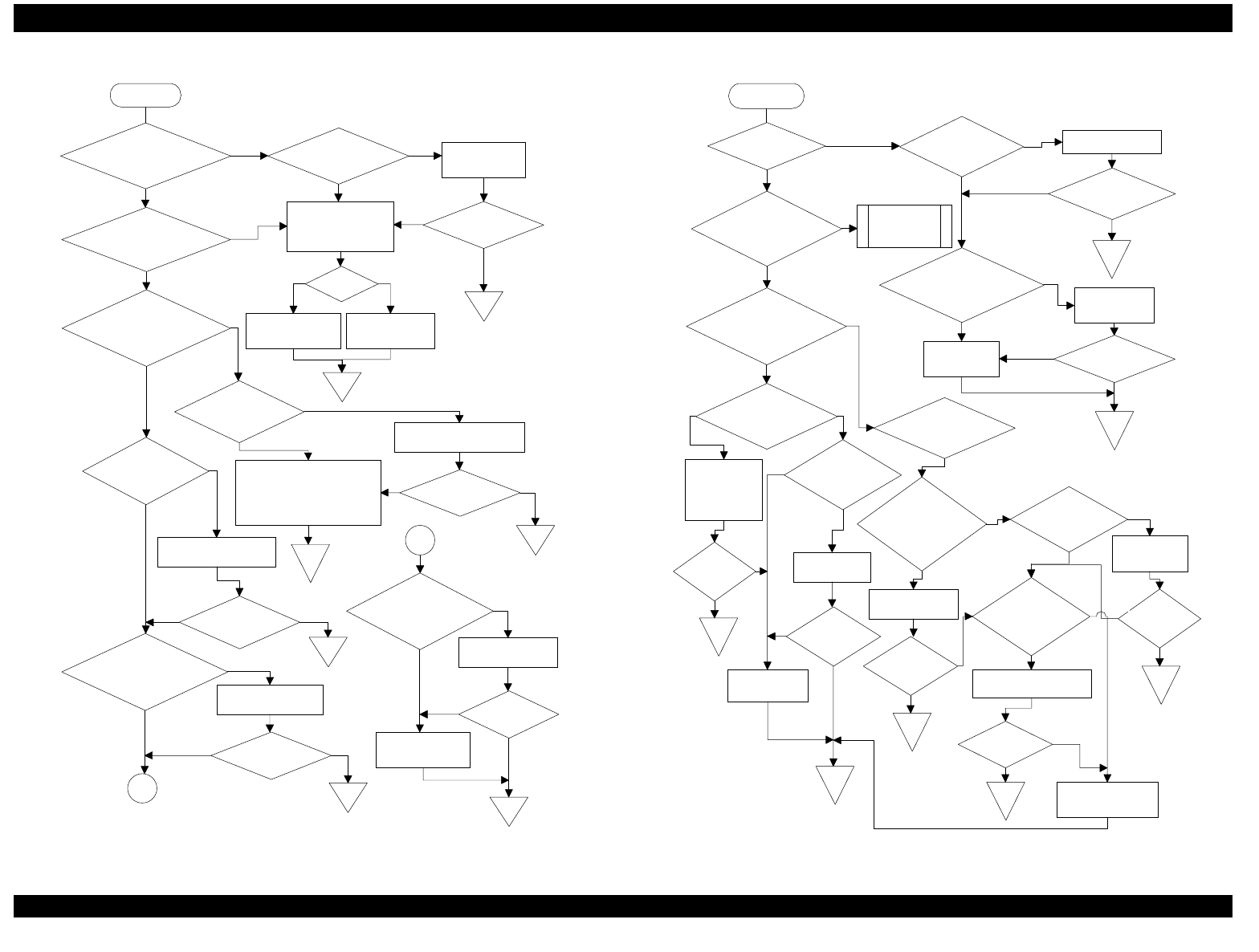
3-5
1. Abnormal Carriage Operation
START
When you turn on
the printer, does the CR
motor rotate?
Is CN11 connected
properly? Connect CN11.
Check the CR motor
coil resistance.
See Table 3-3.
Is the problem
solved?
Does the CR motor
stop during or after
initialization?
END
Is it OK?
NO
YES
NO
YES
YES
NO
Replace the main
board. Replace the CR
motor.
NO
NOYES
When you
move the CR by hand
with the printer off, does
it move freely?
YES
Is the platen gap
adjusted properly?
Is CN4 connected
properly?
END
Adjust the platen gap.
See Chapter 5.
Replace the oil pad on the
carriage unit. Clean and
lubricate the CR shaft.
Is the problem
solved?
END
Connect CN4.
Is the problem
solved?
END
Does the HP sensor
work correctly?
See Table 3-2. Replace the
HP sensor.
Is the problem
solved?
Is the resistance of
the CR motor correct?
See Table 3-3.
A
Replace the
CR motor.
Is the problem
solved?
Replace the main
board.
END
A
YES
NO
NO
YES
YES
NO YES
END
NO
NO YES
YES
NO
NO
END
YES
NO
NO
YESYES
Figure 3-3. Flowchart 1
2-1. Abnormal Paper Feeding
START
END
Does the PF
motor rotate?
Is CN10
connected
properly?
Connect CN10.
Is the problem
solved?
Is paper
ejected automatically
when you turn on the
printer?
See Flowchart
2-2.
Does a paper out
error occur after the
paper is ejected?
Is the resistance of the
PF motor coils correct?
See Table 3-3. Replace the PF
motor.
Replace the
main board. Is the problem
solved?
NO
NO
YES
NO
NO
YES
YES
NO
Does the
printer indicate it is
ready after the paper is
ejected?
YES
NO
Is foreign
material stuck on the
TOP sensor?
NO
Is foreign
material jammed
between the front
or rear PE sensor
and the platen?
Are CN5 and
CN6 connected
properly?
Remove the
substance
blocking the
TOP sensor.
Does the
TOP sensor work
properly?
Is the
problem
solved?
END
YES
END
Replace the
TOP sensor.
Is the
problem
solved?
END
Replace the
main board.
Remove the
foreign material.
Is the
problem
solved?
END
YES
Do the
front and rear
PE sensors work
correctly?
YES
YES NO
YES
Replace the defective
PE sensor.
Is the
problem
solved?
END
Connect CN5
and CN6.
Is the
problem
solved?
END
Replace the main
board.
YES
NO
YES
NO
NO
YES
YES
NO
NO
YES
YES
NO
YES
YES
NO
YES
NO
NO
Figure 3-4. Flowchart 2-1
EPSON FX-2180 Service Manual Chapter 3 Troubleshooting
3-6
2-2. Abnormal Paper Feeding
START
END
When paper is
loaded, is it ejected
automatically?
Is the problem
solved?
Is CN7
connected
properly? Connect CN7.
Does the printer load
sin
g
le sheets properly, but
not load continuous
paper at all?
Is CN12
connected
properly?
Connect
CN12.
Is the problem
solved?
END
Is the FFC
cable OK?
Replace the
cable.
Does the
TOP sensor work
correctly? See
Table 3-2.
Is the problem
solved?
END
Replace the
TOP sensor.
Is the problem
solved?
END
Replace the main
board.
END
Does the
release sensor work
correctly?
Replace the
release
sensor.
Is the
problem
solved?
END
Replace the
main board.
END
YES
NO
YES
NO
NO YES
YES
NO
NO YES
NO
YES
YES
NO
YES
YES
NO
NO
YES
YES
NO
NO
YES
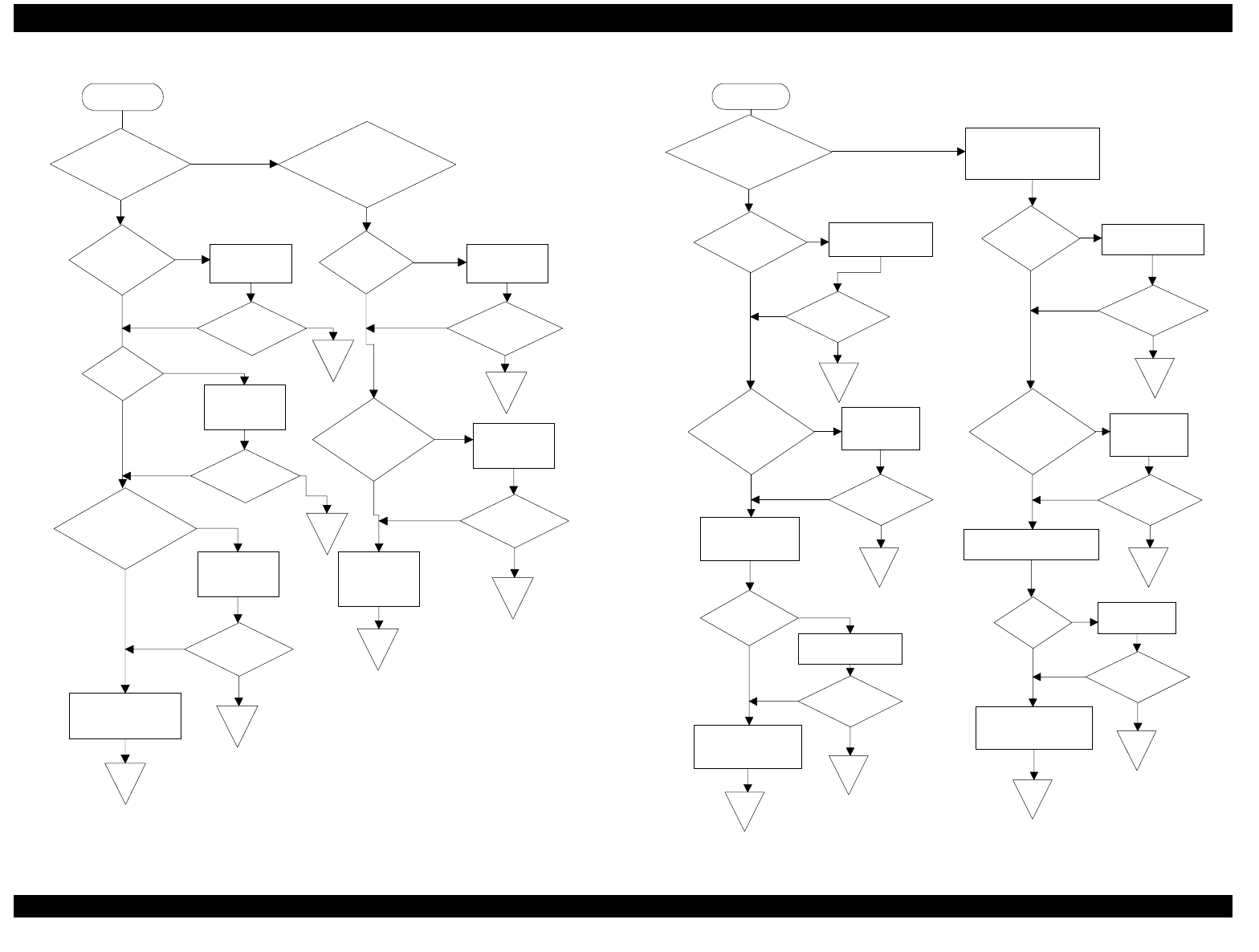
Figure 3-5. Flowchart 2-2
3. Abnormal Power Operation
START
END
Does the Operate
button turn the printer
on and off?
Is the problem
solved?
Is CN7
connected
properly?
Connect CN7. Is the Operate
button working
correctly?
Replace the control
panel board.
Is the problem
solved?
END
Is the FFC
OK?
Is the problem
solved?
END
Replace the FFC.
Is the problem
solved?
END
Replace the main
board.
END
Is control panel
FFC connected
correctly?
Connect the
cable.
Is the problem
solved?
END
Replace the power
supply board.
END
YES
NO
NO
YES
YES
NO
YES
YES
Check the Operate button
on the control panel using
a multimeter.
Is control panel
FFC connected
correctly?
Connect the
cable.
Check the FFC
using a multimeter. Check pin 19 of the FFC.
Is FFC
OK?
Replace the
FFC.
Is the problem
solved?
END
NO
NO
NO
NO
NO
YES
YES
YES
YES
YES
NO
NO
YES
YES
NO
NO
YES
NO
Figure 3-6. Flowchart 3
EPSON FX-2180 Service Manual Chapter 3 Troubleshooting
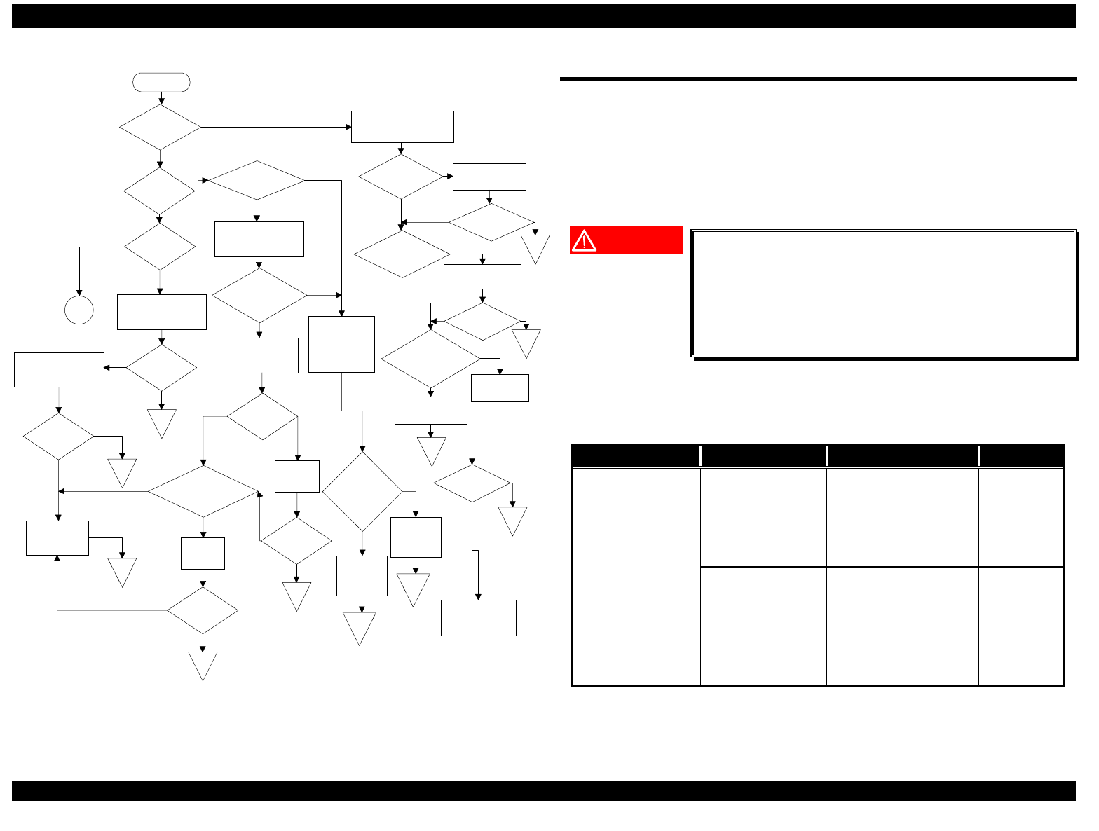
3-7
4. Abnormal Printing
START
Is the self test
printed correctly?
Check the data from the
host PC using the hex
dump mode.
Are all the
dots printed
correctly?
Are any print head
wires broken?
Is the problem
solved?
Are the printer
settings correct? Reset the settings
to their defaults.
END
Are the correct
printer drivers
installed? Install the correct
printer drivers.
Is the problem
solved? END
Does the printer
work correctly with
another printer
cable? Replace the
cable.
Replace the main
board.
END
END
YESNO
YES
NO
YES
NO
NO
YES
NO
NO
YES
YES
NO
Is the problem
solved?
The computer is the
source of the
problem.
YES
NO
Perform the
bidirectional alignment.
(See Chapter 5.)
Is the
problem
solved?
END
Are all the
dots aligned
correctly?
Check the platen
gap/parallelism. (See
Chapter 5.)
Is the
problem
solved?
END
Replace the
print head.
END
Check the print head's
coil resistance as
described in Table 3-1.
Is the print head
coil resistance
correct?
Check the FFC
using a multimeter.
Is the FFC
OK?
Are the bottoms of the
characters missing?
Replace
the FFC.
Is the
problem
solved?
END
Reinstall
the ribbon
mask.
Is the
problem
solved?
END
Test the print
head drivers on
the main board
as described in
Table 3-7.
Are the print
head drivers on
the main board
OK?
Replace the
print head
and the main
board.
END
Replace the
print head.
END
NO
YES
YES
NO
YES
NO
YES
NO
YES
YES
YES
NO
NO
YES
NO
NO
YES
YES
NO
NO
B
YES
Figure 3-7. Flowchart 4
3.4 Repairing the Power Supply Board
The table below provides instructions on how to repair the power supply
board assembly. It lists various power supply board problems and
provides likely causes, checkpoints, and solutions. To determine whether
a component is defective, compare its readings with the correct
waveforms, resistances, and other values listed in the table below. Then
replace the component if necessary.
WARNING
The OPERATE button on the control panel only
turns the secondary power circuit on or off, so the
primary circuit is live as long as the printer is
connected to an AC power outlet. Before you
touch the power supply board or repair it,
disconnect the printer from the AC power outlet.
Note:
Use an oscilloscope to check the waveforms in Table 3-6.
Table 3-6. Repairing the Power Supply Board
Problem Cause Checkpoint Solution
The +35 V and +5
V lines are not
output when the
printer is turned
on.
Diode bridge DB1
is dead.
Measure the DC
voltage between pins
3 and 4 of DB1.
Replace
DB1.
Transformer coil
T1 is open.
Measure the
resistances of the T1
transformer coils at
pins 12 and 15, 9 and
11, 7 and 8, and 3
and 4.
Replace
T1.
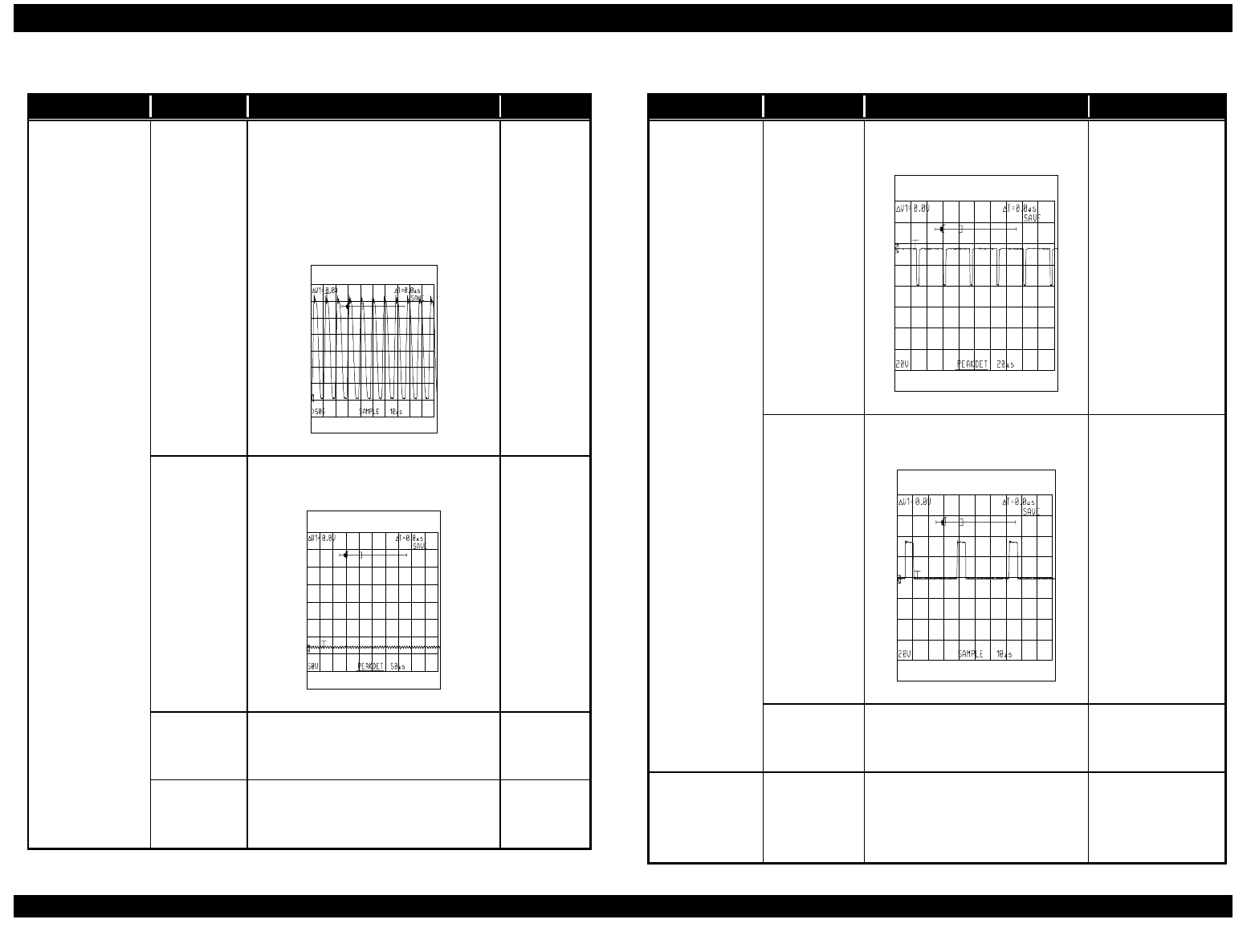
EPSON FX-2180 Service Manual Chapter 3 Troubleshooting
3-8
Table 3-6. Repairing the Power Supply Board (Continued)
Problem Cause Checkpoint Solution
The +35 V and
+5 V lines are
not output
when the
printer is
turned on.
Switching
FET Q1 is
dead.
• Check that the resistance
between the source and the
drain is infinite.
• Check the voltage waveform
between the source and the
drain of Q1.
Figure 3-8. Waveform 1
Replace
Q1.
PC1 is
dead.
Check the waveform between
pins 3 and 4.
Figure 3-9. Waveform 2
Replace
PC1.
Q32 is
dead.
Check that the resistance
between the collector and the
emitter is infinite.
Replace
Q32.
Q31 is
dead.
Check that the resistance
between the source and the drain
is infinite.
Replace
Q31.
Table 3-6. Repairing the Power Supply Board (Continued)
Problem Cause Checkpoint Solution
The +5 V line
is not output.
Chopper IC
IC51 is
dead.
Check the waveform at pin 8
of IC51.
Figure 3-10. Waveform 3
Replace IC51.
Q51 is
dead.
Check the waveform at
the collector of Q51.
Figure 3-11. Waveform 4
Replace Q51.
L51 is
dead.
Check the resistance
between the terminals of
L51.
Replace L51.
The PWDN
signal is
constantly
HIGH.
IC51 is
dead.
Check if the voltage of pin 6
exceeds 1.3 V. If it does,
IC51 is dead.
Replace IC51.
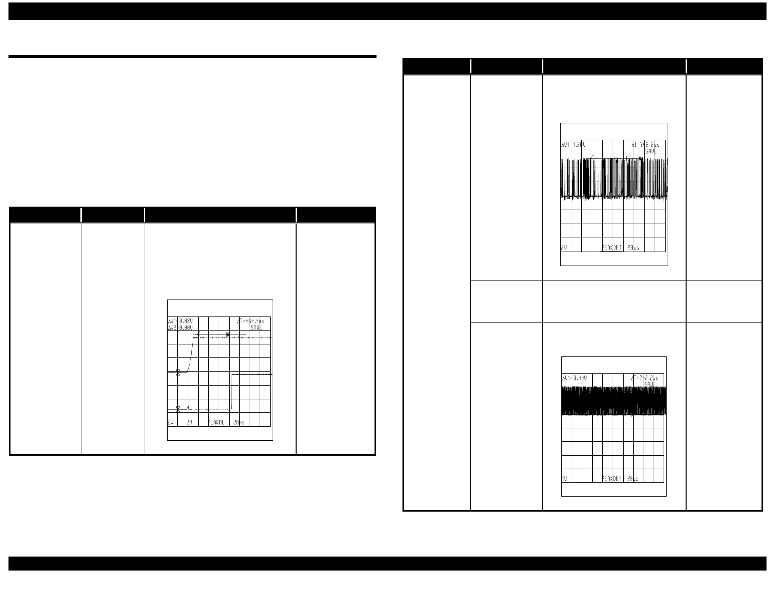
EPSON FX-2180 Service Manual Chapter 3 Troubleshooting
3-9
3.5 Repairing the Main Board Assembly
The table below provides instructions on how to repair the main board
assembly. It lists various main board problems and provides likely causes,
checkpoints, and solutions. To determine whether a component is
defective, compare its readings with the correct waveforms, resistances,
and other values listed in the table below. Then replace the component if
necessary.
Note:
Use an oscilloscope to check the waveforms in Table 3-7.
Table 3-7. Repairing the Main Board Assembly
Problem Cause Checkpoint Solution
The printer
does not
operate at all.
Reset IC
IC15 is
defective.
Check the voltage waveforms of
the VCC signal (CH 1: pin 7 of
IC15) and the /RESET signal
(CH 2: pin 5 of IC15) when the
printer is turned on.
CH 1
CH 2
Figure 3-12. Waveform 5
Replace the
main board or
IC15.
Table 3-7. Repairing the Main Board Assembly (Continued)
Problem Cause Checkpoint Solution
The printer
does not
operate at
all.
The PROM
(IC5) is not
selected.
Check for a change in the
signal (HIGH to LOW or LOW
to HIGH) at pin 137 of IC1.
Figure 3-13. Waveform 6
Replace the
main board.
The PSRAM
(IC3) is not
selected.
Check for a change in the
signal (HIGH to LOW or LOW
to HIGH) at pin 132 of IC1.
Replace the
main board.
The CPU
(IC2) is
defective.
Check the oscillator signal at
pin 26 or 27 of the CPU.
Figure 3-14. Waveform 7
Replace the
main board.
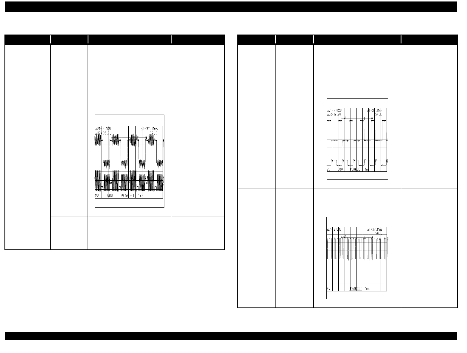
EPSON FX-2180 Service Manual Chapter 3 Troubleshooting
3-10
Table 3-7. Repairing the Main Board Assembly (Continued)
Problem Cause Checkpoint Solution
Carriage
operation is
abnormal.
The CPU or
IC9 is
defective.
• Check the input signal
waveforms (CH 1) at
pins 5, 6, 16, and 17 of
IC9.
• Check the output signal
waveforms (CH 2) at
pins 1, 8, 11, and 18 of
IC9.
CH 1
CH 2
Figure 3-15. Waveform 8
• If an input
signal is not
correct,
replace the
main board.
• If an output
signal is not
correct,
replace IC9 or
the main
board.
IC1 is
defective.
Check the output signals at
pins 62, 63, 64, and 65 of
IC1.
If an output signal
is not correct,
replace the main
board.
Table 3-7. Repairing the Main Board Assembly (Continued)
Problem Cause Checkpoint Solution
Paper
feeding is
abnormal.
IC1, IC2, or
IC12 is
defective.
• Check the input signal
waveforms (CH 1) at
pins 26 and 43 of IC12.
• Check the output signal
waveforms (CH 2) at pins 3,
6, 18, and 21 of IC12.
CH 1
CH 2
Figure 3-16. Waveform 9
• If an input signal
is not correct,
replace the
main board.
• If an output
signal is not
correct, replace
IC12 or the main
board.
No data is
printed.
The CPU is
defective.
Check the output signal
waveforms at pin 15 or 19 of
IC2.
Figure 3-17. Waveform 10
If an output signal
is not correct,
replace the main
board.
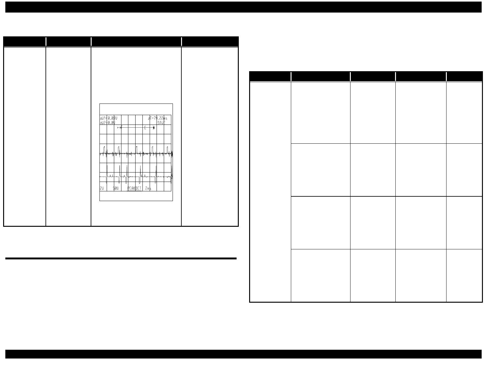
EPSON FX-2180 Service Manual Chapter 3 Troubleshooting
3-11
Table 3-7. Repairing the Main Board Assembly (Continued)
Problem Cause Checkpoint Solution
A particular
dot does not
print.
IC1 is
defective, or
one of the
print head
drive
transistors
(Q2 − Q19) is
defective.
• Check the input signal
waveform (CH 1) at the
base of each transistor.
• Check the output signal
waveform (CH 2) at the
collector for each transistor.
CH 1
CH 2
Figure 3-18.
Waveform 11
• If an input
signal is not
correct, replace
the main board.
• If an output
signal is not
correct, replace
the transistor or
the main board.
3.6 Repairing the Printer Mechanism
The table below describes how to repair the printer mechanism. It lists
various printer mechanism problems and symptoms, and provides likely
causes, checkpoints, and solutions. The checkpoint column lists what to
check and indicates how the printer mechanism works when it is operating
properly. The solution column tells you how to repair the printer
mechanism.
For replacement and adjustment instructions, see Chapter 4,
“Disassembly and Assembly,” and Chapter 5, “Adjustment.” If the same
symptom recurs after you repair the printer mechanism, select another
probable cause and repair the printer mechanism again.
Table 3-8. Repairing the Printer Mechanism
Problem Symptom Cause Checkpoint Solution
Carriage
operation is
abnormal.
When you turn on
the printer, the CR
motor does not
rotate at all.
The CR
motor is
defective.
Measure the
CR motor’s coil
resistance. It
should be
approx. 2.7 Ω.
(See Table
3-3.)
Replace
the CR
motor.
When you turn on
the printer, the CR
motor does not
rotate at all and
the control panel
LEDs flash.
CN11 is not
properly
connected to
the main
board.
Check the
connection.
Connect
CN11.
When you turn on
the printer, the CR
motor rotates but
the carriage does
not move.
The timing
belt has
come off the
pinion gear of
the CR
motor.
Check the
timing belt.
Replace
the timing
belt.
The carriage
moves slightly and
then stops.
The platen
gap is too
narrow.
Move the
carriage by
hand to check if
it moves
smoothly.
Check the
platen gap
and adjust
it if it is too
small. See
Chapter 5.
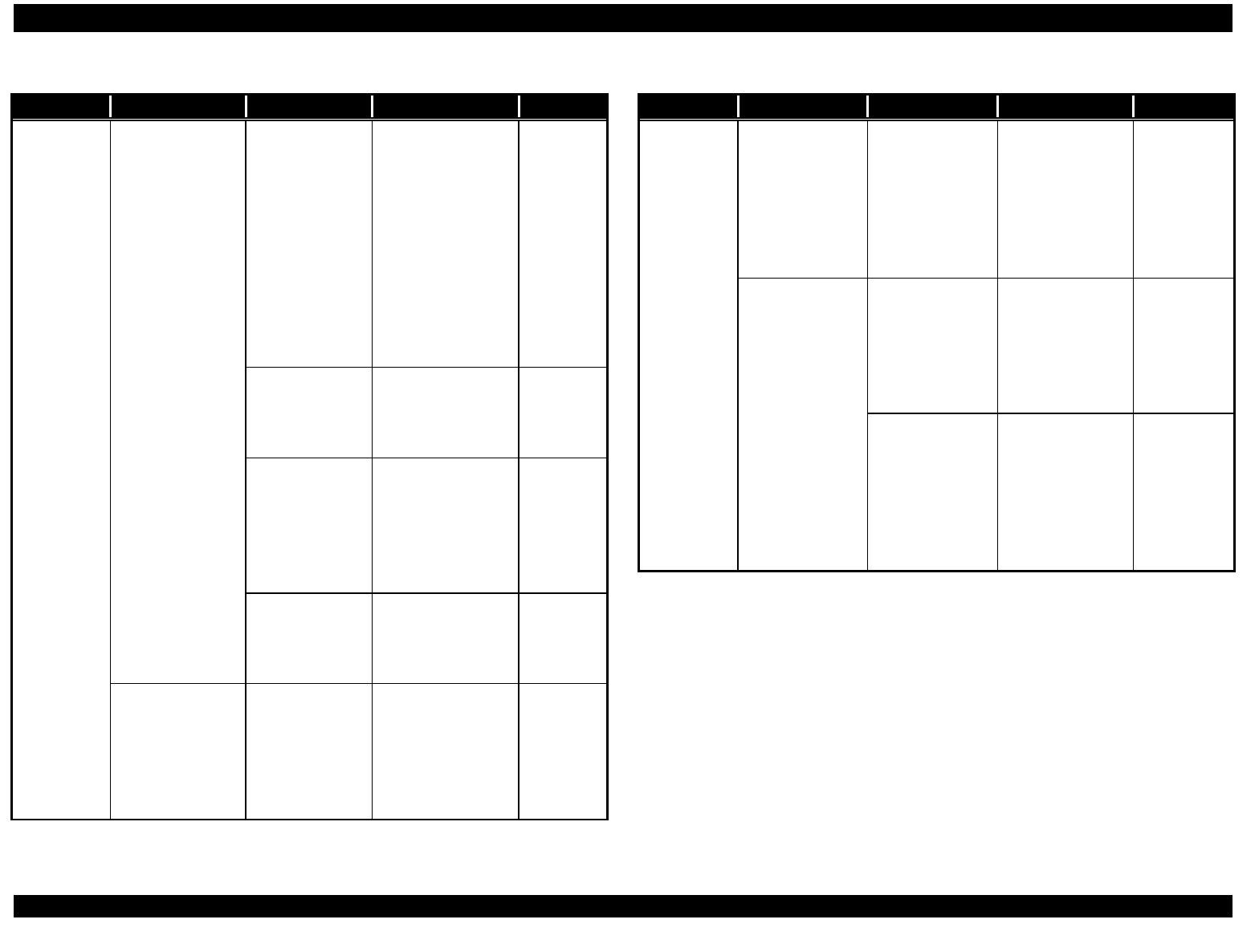
EPSON FX-2180 Service Manual Chapter 3 Troubleshooting
3-12
Table 3-8. Repairing the Printer Mechanism (Continued)
Problem Symptom Cause Checkpoint Solution
Carriage
operation is
abnormal.
The carriage
moves slightly
and then stops.
There is a lack
of lubrication,
or foreign
material is
stuck on the
CR shaft or oil
pad.
• Move the
carriage by
hand to check if
it moves
smoothly.
• Check the CR
shaft and oil
pad to see if
they are
sufficiently
lubricated.
Replace
the oil
pad.
Remove
the CR
shaft,
clean it,
and then
lubricate
it.
The HP sensor
is defective.
Check the
operation of the
HP sensor. (See
Table 3-2.)
Replace
the HP
sensor.
Foreign
material is
lodged
between the
HP sensor
terminals.
Check the HP
sensor.
Remove
any
foreign
material.
The HP sensor
is not properly
connected to
CN4.
Check the
connection.
Connect
CN4.
The carriage
moves left
(toward the
home position)
and strikes the
printer frame.
The HP sensor
is defective.
Check the
operation of the
HP sensor. (See
Table 3-2.)
Replace
the HP
sensor.
Table 3-8. Repairing the Printer Mechanism (Continued)
Problem Symptom Cause Checkpoint Solution
Printing is
abnormal.
No image is
printed.
The common
wires in the
print head FFC
are dis-
connected or
there is no
continuity.
Check the
common wires
in the print head
FFC.
Replace
the print
head FFC.
The printer
does not print
certain dots.
The print head
is defective.
Measure the coil
resistance of the
print head. It
should be
approx. 16.4 Ω.
(See Table 3-1.)
Replace
the print
head.
The common
wires in the
print head FFC
are dis-
connected, or
there is no
continuity.
Check the
continuity in the
FFC.
Replace
the print
head FFC.
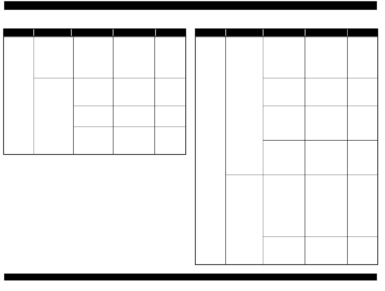
EPSON FX-2180 Service Manual Chapter 3 Troubleshooting
3-13
Table 3-8. Repairing the Printer Mechanism (Continued)
Problem Symptom Cause Checkpoint Solution
Printing is
uneven (lighter
or darker on the
left side of the
page than on
the right side).
Platen
parallelism is
not adjusted
properly.
Check the
platen
parallelism.
(See Chapter 5.)
Adjust the
platen
parallelism.
(See
Chapter 5.)
Printing is too
light.
The platen gap
is too wide.
Check the
platen gap. (See
Chapter 5.)
Adjust the
platen gap.
(See
Chapter 5.)
The print head
is defective.
Check if the tips
of the dot wires
are worn.
Replace
the print
head.
The print head
drivers on the
main board are
bad.
Check the print
head drivers on
the main board.
(See Table 3-7.)
Replace
the main
board.
Table 3-8. Repairing the Printer Mechanism (Continued)
Problem Symptom Cause Checkpoint Solution
Paper
feeding is
abnormal.
The PF motor
does not rotate
at all.
The PF motor is
defective.
Measure the coil
resistance of the
PF motor. It
should be
approx. 16.1 Ω.
(See Table 3-3.)
Replace
the PF
motor.
CN10 is not
properly
connected to the
main board.
Check the
connection.
Connect
CN10.
The front or rear
PE sensor is
defective.
Check the
operation of the
front and rear PE
sensors.
(See Table 3-2.)
Replace
the front or
rear PE
sensor.
The front or rear
PE sensor is not
installed
correctly.
Check the front
and rear PE
sensor
connections.
Install the
front and/or
rear PE
sensor
correctly.
When you turn
on the printer,
it ejects the
paper
automatically
and then
indicates it is in
the ready
state.
Foreign material
is stuck on the
TOP sensor.
Check the TOP
sensor.
Remove
any foreign
material
from the
TOP
sensor.
The TOP sensor
is defective.
Check the
operation of the
TOP sensor.
(See Table 3-2.)
Replace
the TOP
sensor.
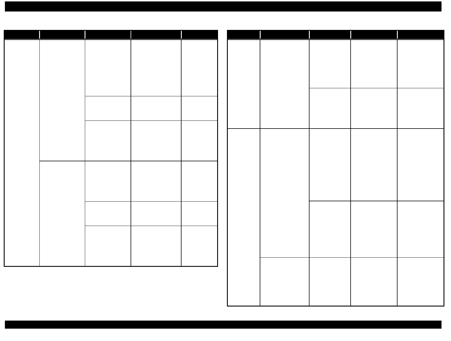
EPSON FX-2180 Service Manual Chapter 3 Troubleshooting
3-14
Table 3-8. Repairing the Printer Mechanism (Continued)
Problem Symptom Cause Checkpoint Solution
Paper
feeding is
abnormal.
When you turn
on the printer, it
ejects the
paper auto-
matically and a
paper out error
occurs.
Foreign
material is
lodged
between the
front or rear PE
sensor and the
platen.
Remove and
check the platen.
Remove
any foreign
material
from the
platen.
CN5 or CN6 is
disconnected.
Check the
connections.
Connect
CN5 and/or
CN6.
The front or
rear PE sensor
is defective.
Check the
operation of the
front and rear PE
sensors. (See
Table 3-2.)
Replace
the front or
rear PE
sensor.
When you load
paper, the
printer ejects it
automatically.
The TOP
sensor’s FFC is
not properly
connected to
CN7.
Check the
connection.
Connect
the FFC.
The FFC is
defective.
Check the FFC’s
continuity using a
multimeter.
Replace
the FFC.
The TOP
sensor is
defective.
Check the
operation of the
TOP sensor.
(See Table 3-2.)
Replace
the TOP
sensor.
Table 3-8. Repairing the Printer Mechanism (Continued)
Problem Symptom Cause Checkpoint Solution
Paper
feeding is
abnormal.
The printer loads
single-sheet
paper correctly,
but does not
load continuous
paper at all.
CN12 is not
connected
properly.
Check the
connection.
Connect CN12.
One of the
paper release
sensors is
defective.
Check the
operation of the
paper release
sensors. (See
Table 3-2.)
Replace the
paper release
sensor.
Ribbon
feeding is
abnormal.
The printer does
not feed the
ribbon.
The ribbon
cartridge is
defective.
Remove the
cartridge, and
turn the ribbon
feed knob by
hand to check if
the ribbon
cartridge feeds
the ribbon
normally.
Replace the
ribbon
cartridge.
Foreign
material is
caught in the
ribbon driving
gears.
Check the
ribbon driving
gears.
Remove any
foreign material
caught in the
gears or
replace the
ribbon
cartridge.
The ribbon feeds
properly only
when the
carriage moves
in one direction.
The ribbon
driving gears
are defective.
Move the
carriage by
hand to check if
the gears
function
normally.
Replace the
ribbon driving
mechanism.

DISASSEMBLY AND ASSEMBLY
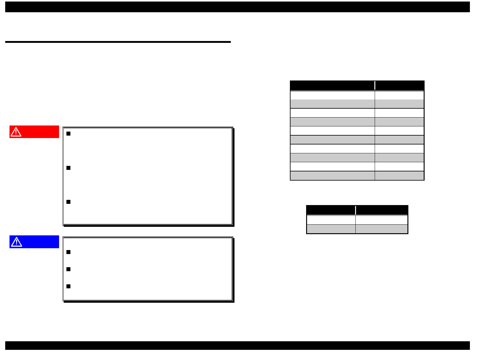
EPSON FX-2180 Service Manual Chapter 4 Disassembly and Assembly
4-1
4.1 Overview
This section provides warnings and cautions about disassembling and
assembling the printer, and information about tools and screws. It also
describes how to check the printer after you repair it to make sure it is
operating properly.
4.1.1 Precautions
Follow the precautions below when disassembling or assembling the
printer.
WARNING
Before disassembling, assembling, or adjusting
the printer, disconnect the power supply cable
from the AC power socket. Failure to do so can
cause physical injury.
The power switch is wired in the secondary
circuitry of the power supply board. Therefore,
the power supply’s primary circuitry remains
live even after the printer is turned off.
Never touch primary parts of the power supply
unit (including the heat sink) while the printer is
plugged in.
CAUTION
To maintain efficient printer operation:
Use only recommended tools for repair or
maintenance work.
Use only recommended lubricants and
adhesives. (See Chapter 6.)
Adjust the printer only as described in this
manual.
4.1.2 Tools
Tables 4-1 and 4-2 list the tools recommended for disassembling,
assembling, or adjusting the printer. Use only tools that meet these
specifications.
Table 4-1. Recommended Tools
Tool Part No.
Round-nose pliers B740400100
Wire cutters B740500100
Tweezers B741000100
Soldering iron B740200100
E-ring holder #2.5 B740800400
Phillips screwdriver No. 2 B743800200
Standard screwdriver B743000100
Thickness gauge B776702201
Needle-nose pliers —
Pin drive —
Note: All tools are commercially available.
Table 4-2. Equipment Required for Maintenance
Description Specification
Multimeter —
Oscilloscope 50 MHz
Note: An oscilloscope is required only for servicers who repair to the
component level.
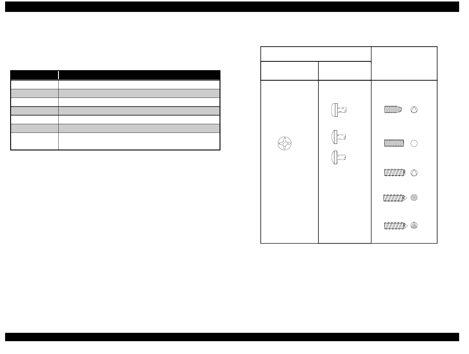
EPSON FX-2180 Service Manual Chapter 4 Disassembly and Assembly
4-2
4.1.3 Specifications for Screws
Table 4-3 lists the abbreviations used in this chapter for small parts, such
as screws and washers.
Table 4-3. Screw Types and Abbreviations
Abbreviation Part Name
CPS Cross-recessed pan head S-tight screw
CBB Cross-recessed bind head B-tight screw
CBS Cross-recessed bind head S-tight screw
CBN Cross-recessed bind head N-tight screw
CBC Cross-recessed bind head C-lamitite screw
CBA Cross-recessed bind head A-lamitite screw
CB(O) Cross-recessed bind head with outside-toothed lock
washer
Table 4-4 illustrates the various screw types.
Table 4-4. Screw Types
Cross-recessed head Bind
Normal
Top Side
(with notch)
S-tight
B-tight
C-lamitite
A-lamitite
Pan
Body
Head
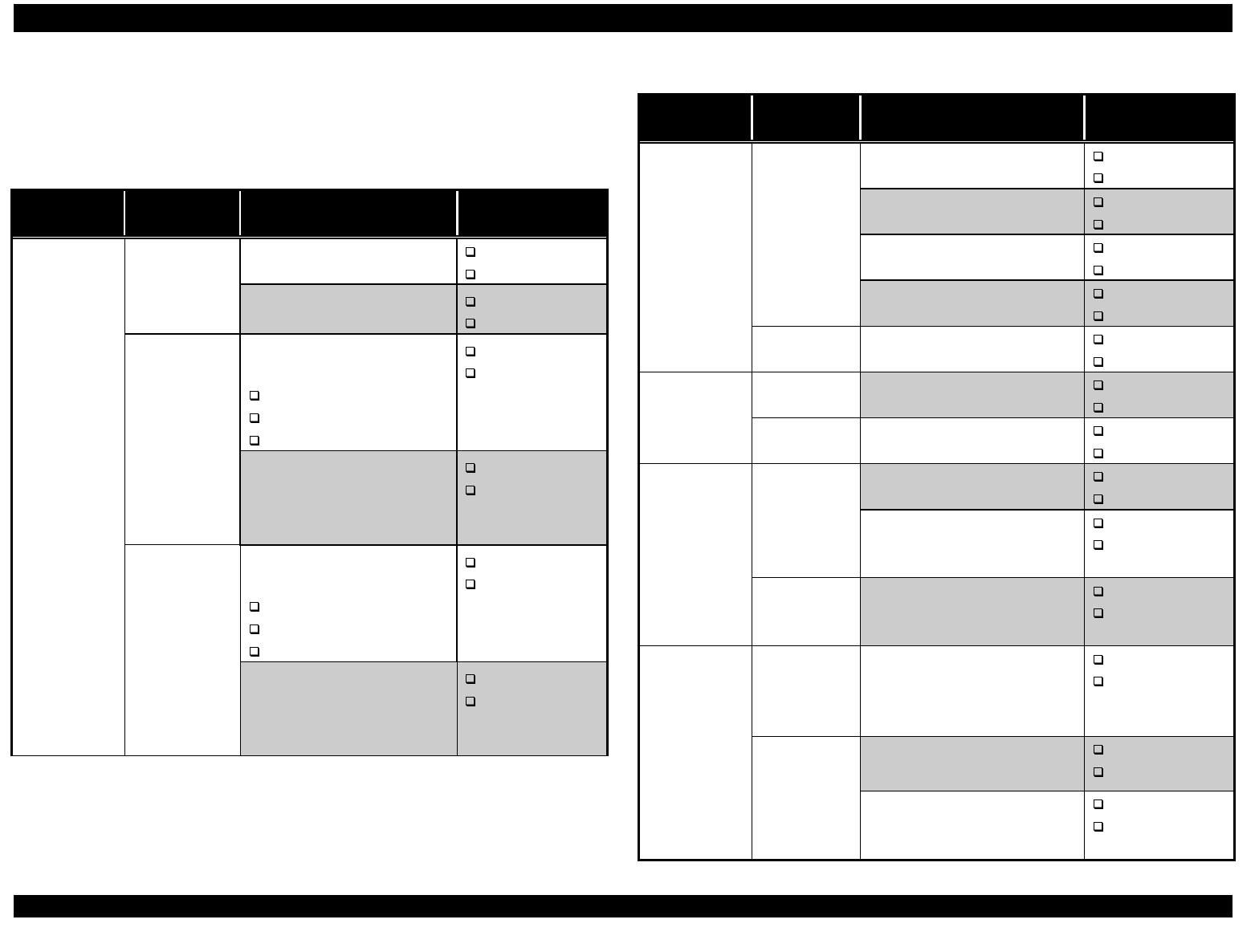
EPSON FX-2180 Service Manual Chapter 4 Disassembly and Assembly
4-3
4.1.4 Service Check After Repair
After you repair the printer and before you return it, use the checklist in
Table 4-5 to make sure the printer is operating properly.
Table 4-5. Inspection Checklist for the Repaired Printer
Category Item to
Check Question to Answer Checkmark
Are any wires broken? Checked
Not necessary
Print head
Are any wires worn out? Checked
Not necessary
Does the carriage move
smoothly?
Movement noisy
Mechanism dirty
Mechanism oily
Checked
Not necessary
Carriage
mechanism
Is the CR motor running
at the correct
temperature (not
overheating)?
Checked
Not necessary
Is paper advancing
smoothly?
Movement noisy
Mechanism dirty
Mechanism oily
Checked
Not necessary
Printer unit
Paper
advance
mechanism
Is the PF motor running
at the correct
temperature (not
overheating)?
Checked
Not necessary
Table 4-5. Inspection Checklist for the Repaired Printer
(Continued)
Category Item to
Check Question to Answer Checkmark
Is the type of paper in the
printer feeding smoothly?
Checked
Not necessary
Is the tractor feeding
paper correctly?
Checked
Not necessary
Is the paper path clear of
all obstructions?
Checked
Not necessary
Paper path
Is the platen free of
damage?
Checked
Not necessary
Printer unit
(continued)
Ribbon
mask
Is the ribbon mask free of
distortion?
Checked
Not necessary
Testing Self test Does the self test print
correctly?
Checked
Not necessary
Online test Does the online test print
correctly?
Checked
Not necessary
Adjustment Print head Is the platen gap adjusted
correctly?
Checked
Not necessary
Is the bidirectional print
position adjusted
correctly?
Checked
Not necessary
Default
settings
Have the user-change-
able settings been reset
to the default settings?
Checked
Not necessary
System
upgrade
ROM
version
What is the ROM
version? Install the latest
ROM version, if
necessary.
Checked
Not necessary
Shipment Has the ribbon been
removed?
Checked
Not necessary
Are all the necessary
parts included in the
shipment?
Checked
Not necessary
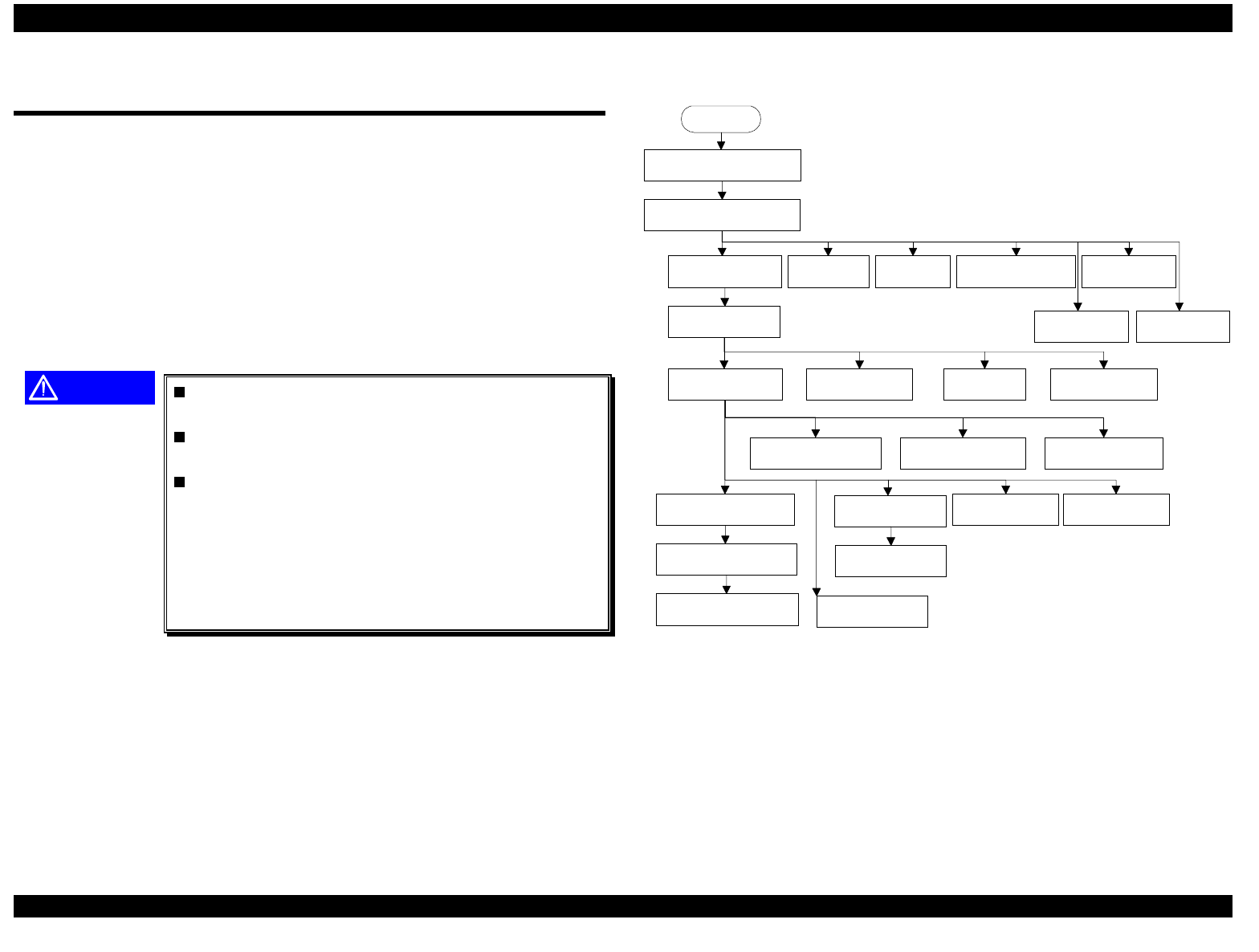
EPSON FX-2180 Service Manual Chapter 4 Disassembly and Assembly
4-4
4.2 Disassembly and Assembly
This section describes procedures for disassembling and assembling the
main components of the printer. When the procedure for installing a
component is simply the reverse of removing the component, this chapter
does not describe the assembly procedure. If necessary, special notes on
assembling or adjusting a component are given at the end of the
description of each procedure. Be sure to follow the instructions in these
notes.
The exploded diagrams in the appendix show how the components fit
together. Refer to them as necessary.
CAUTION
Before you disassemble any part of the printer,
read the warnings in section 4.1.1.
Before you disassemble the printer, follow the
instructions in section 4.2.1.
Whenever you repair the printer, wipe the
surface of the paper width (PW) sensor
assembly with a soft cloth, and keep it clean to
avoid abnormal operation. If the surface is dirty
because of any adhering material, sensor
sensitivity decreases and printer operation is
impaired.
The flowchart below shows the order in which to disassemble the printer.
START
Disconnect the printer's power
cord and interface cable
Prepare for disassembly
Remove the panel
board assembly Remove the
print head
Remove the
HP sensor Remove the
PW sensor Remove the
platen assembly
Remove the upper
housing assembly
Remove the case
open sensor
Remove the CR motor
assembly
Remove the
printer mechanism
Remove the
main board
Remove the power
supply board
Remove the PF motor
assembly Remove the
PG sensor
Remove the right
frame assembly
Disassemble the
right frame assembly
Remove the left frame
assembly
Remove the RD assembly
Remove the CR assembly
Remove the rear PE
sensor Remove the front
PE sensor
Remove the
platen gear
Remove the
ribbon mask
Remove the right sub
frame assembly
Figure 4-1. Flowchart for Disassembling the Printer
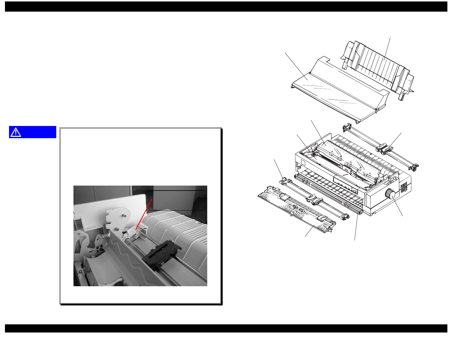
EPSON FX-2180 Service Manual Chapter 4 Disassembly and Assembly
4-5
4.2.1 Preparing to Disassemble the Printer
Before you disassemble the printer, disconnect the printer’s power cord
and interface cable, and remove any paper loaded in the printer. Then
remove the following parts from the printer:
front edge guide assembly rear tractor assembly bottom cover
rear edge guide assembly paper eject assembly printer cover
front tractor assembly front cover ribbon cartridge
platen knob
Refer to Figure 4-3.
CAUTION
Remove the paper eject assembly. Then remove
the front and rear tractor assemblies by pushing
the tabs to release the hooks on both sides. (See
Figure 4-2 to locate the tabs on the rear tractor.)
When reinstalling the tractors, be sure to snap the
hooks onto the projecting parts.
rear tractor tab
(1 of 2)
Figure 4-2. Removing the Rear Tractor
front edge guide assem bly front cover
fro n t tra c to r a s s e m b ly
rear tractor assem bly
paper eject assem bly
rear edge guide assem bly
printer cover
ribbon cartridge
platen knob
Figure 4-3. Parts to Remove Before Disassembling the Printer
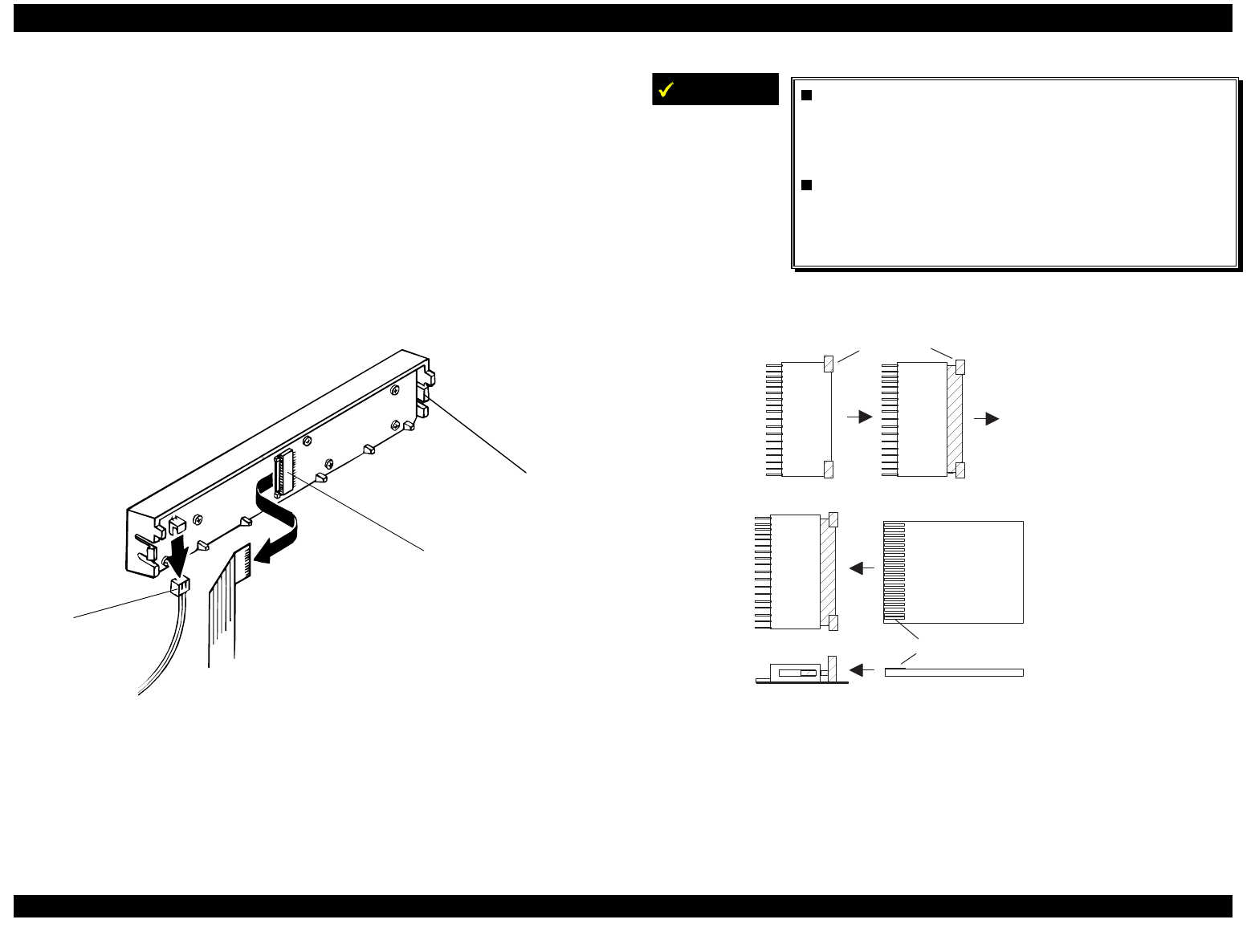
EPSON FX-2180 Service Manual Chapter 4 Disassembly and Assembly
4-6
4.2.2 Removing the Panel Board Assembly
1. Remove the printer cover and ribbon cartridge. (See section 4.2.1.)
2. Release the left clips for the panel board assembly by pushing them
from the cutout located on the inside front of the upper housing
assembly.
3. Release the flexible flat cable (FFC) by sliding the lock cover of
connector CN1 as shown in Figure 4-5. Then disconnect the FFC from
connector CN1 and disconnect connector CN2 from the panel board
assembly.
CN1
CN2
left clip
Figure 4-4. Removing the Panel Board Assembly
4. Remove the panel board assembly from the upper housing assembly.
IMPORTANT
Before disconnecting the FFC from CN1, slide
the lock cover for CN1 as shown in Figure 4-5.
Then disconnect the FFC from CN1. After you
reconnect the FFC for CN1, lock the lock cover.
The FFC must be connected properly, as shown
in Figure 4-5. Connect it so that the exposed
terminals of the FFC face upward against the
panel board.
lock cover for C N 1
CN1 FFC
S lide the lock cover
in th is d ire c tio n
F F C fa c e w ith e x p o s e d te rm in a ls
CN1 CN1
Figure 4-5. Disconnecting and Connecting CN1 and the FFC
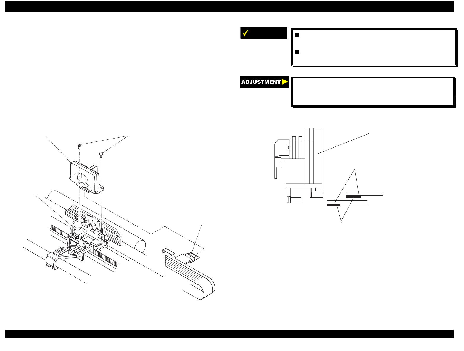
EPSON FX-2180 Service Manual Chapter 4 Disassembly and Assembly
4-7
4.2.3 Removing the Print Head
1. Remove the printer cover and ribbon cartridge. (See section 4.2.1.)
2. Remove the two CBS screws (3 × 10) securing the print head to the
CR assembly.
3. Remove the print head from the CR assembly.
4. Disconnect the two wide FFCs from the print head and then
disconnect the narrow FFC from the connector on the CR cover.
CBS screws (3 x 10)
print head
FFCs
CR assem bly
Figure 4-6. Removing the Print Head
IMPORTANT
The FFCs must be connected properly, as
shown in Figure 4-7.
The tightening torque for the CBS screws is
0.59 - 0.78 Nm (6 - 8 Kgf-cm).
Perform the platen gap/parallelism, bidirectional
print alignment, factory settings, and TPE level
reset adjustments. (See Chapter 5.)
print head FFC s
direction the exposed term inals of the FFC s face
print head
Figure 4-7. Connecting the Print Head FFCs
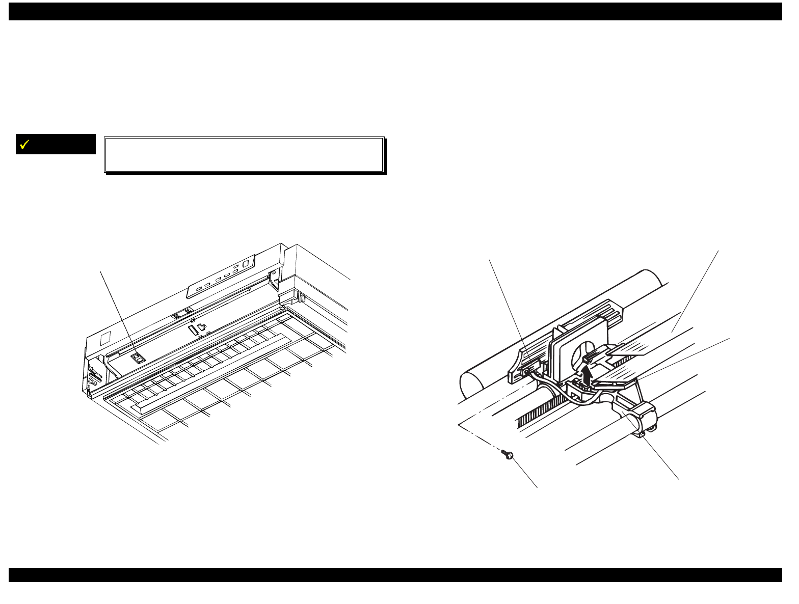
EPSON FX-2180 Service Manual Chapter 4 Disassembly and Assembly
4-8
4.2.4 Removing the HP Sensor
1. Remove the printer cover, ribbon cartridge, front edge guide, and front
cover. (See section 4.2.1.)
2. Disconnect the connector cable for the HP sensor.
IMPORTANT
Note the orientation of the HP sensor so you can
reinstall it the same way. See Figure 4-8.
3. Remove the HP sensor from the front paper entrance by pushing up
and releasing the two clips at the bottom of the HP sensor.
2 clips securing the HP sensor
Figure 4-8. Removing the HP Sensor
4.2.5 Removing the PW Sensor Assembly
1. Remove the printer cover and ribbon cartridge. (See section 4.2.1.)
2. Remove the print head. (See section 4.2.3.)
3. Remove the CB screw (2.5 × 5) securing the PW sensor to the ribbon
mask holder.
4. Release the three clips on the CR cover that secure it to the bottom of
the CR assembly. Then lift the cover slightly.
5. Remove the FFC from the PW sensor connector on the CR cover.
6. Remove the PW sensor assembly along with the CR cover by pushing
and releasing the clip for the CR cover, as shown in Figure 4-9.
PW sensor assem bly
CB screw (2.5 x 5)
C R cover
CR assembly
PW sensor FFC
Figure 4-9. Removing the PW Sensor Assembly
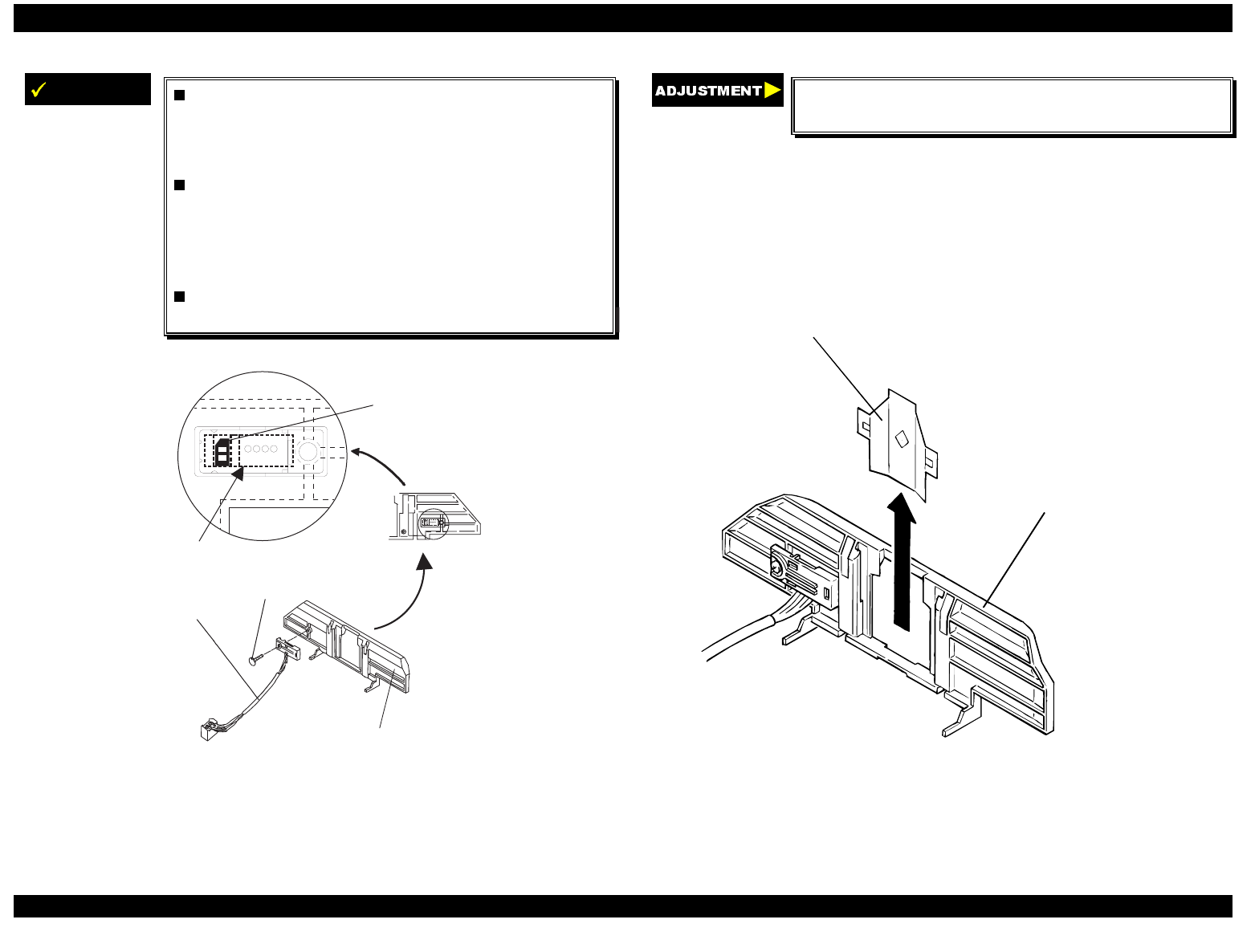
EPSON FX-2180 Service Manual Chapter 4 Disassembly and Assembly
4-9
IMPORTANT
Mount the PW sensor assembly onto the ribbon
mask holder groove, aligning the bottom line of
the micro photo sensor with the bottom line of
the groove.
Whenever you remove the PW sensor assembly,
clean the surface of the sensor by wiping it with
a soft cloth. If the PW sensor is not clean, the
printer may operate incorrectly. For example, it
may print on the platen surface.
The tightening torque for the CB screw is 0.08 -
0.12 Nm (0.8 - 0.12 Kgf-cm).
CB screw (2.5 x 5)
PW sensor assem bly
ribbon m ask holder
PW sensor view ed
through the
ribbon m ask holder
The bold dashed lines indicate the grooves.
m icro photo sensor
Figure 4-10. Installing the PW Sensor Assembly
After you replace the PW sensor assembly, reset
the TPE level. (See Chapter 5.)
4.2.6 Removing the Ribbon Mask
1. Remove the printer cover, ribbon cartridge, and print head. (See
sections 4.2.1 and 4.2.3.)
2. Using tweezers, remove the ribbon mask from the ribbon mask holder,
as shown in Figure 4-11.
ribbon mask
ribbon mask holder
Figure 4-11. Removing the Ribbon Mask
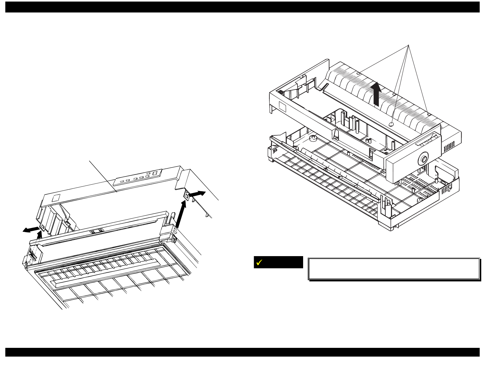
EPSON FX-2180 Service Manual Chapter 4 Disassembly and Assembly
4-10
4.2.7 Removing the Upper Housing Assembly
1. Remove the printer cover, rear edge guide assembly, paper eject
assembly, and rear tractor unit. (See section 4.2.1.)
2. Remove the panel board assembly. (See section 4.2.2.)
3. Remove the four CBB screws (4 × 4) securing the upper housing
assembly. (Figure 4-13 shows the screw locations.)
4. Remove the platen knob.
5. Release the two hooks from the holes on both sides of the upper
housing assembly near the front, and release the tab in the middle
front of the upper housing assembly. Then lift up the front of the upper
housing assembly.
tab
Figure 4-12. Releasing the Upper Housing Assembly Hooks and Tab
6. Remove the upper housing assembly.
CBB screws (4 x 4)
Figure 4-13. Removing the Upper Housing Assembly
IMPORTANT
The tightening torque for the four CBB screws is
0.98 - 1.22 Nm (10 - 12 Kgf-cm).
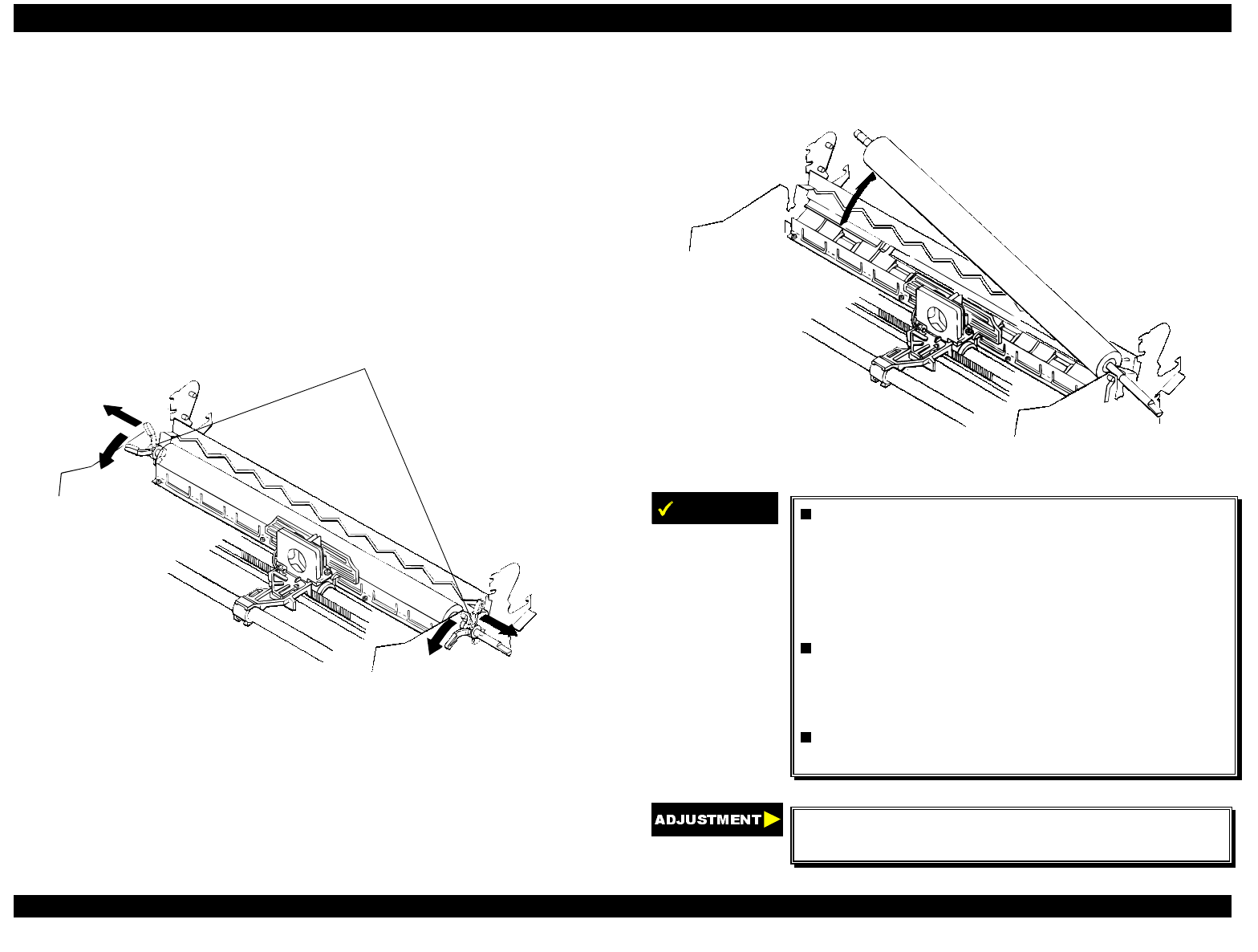
EPSON FX-2180 Service Manual Chapter 4 Disassembly and Assembly
4-11
4.2.8 Removing the Platen Assembly
1. Remove the printer cover, ribbon cartridge, and platen knob. (See
section 4.2.1.)
2. Remove the print head, ribbon mask, and upper housing assembly.
(See sections 4.2.3, 4.2.6, and 4.2.7.)
3. Move the paper release lever to the pull tractor position.
4. Release the locks for the left and right bushings (8 mm) by pushing
the lever holders for the bushings out and then forward, as shown in
Figure 4-14.
left and ri
g
ht bushin
g
s (8 mm)
Figure 4-14. Releasing the Locks for the Bushings
5. Slide the platen assembly to the right, and move the print head to the
right edge.
6. Pull up the left edge of the platen assembly by tilting it backward.
Then pull up the right edge of the platen assembly.
Figure 4-15. Removing the Platen Assembly
IMPORTANT
Before installing the platen assembly in the
printer mechanism, move the print head to the
right edge of the CR shaft, and move the paper
release lever to the pull tractor position.
This
helps you mount the platen assembly more
easily.
After installing the platen assembly in the
printer mechanism, make sure the locks for
both the left and right bushings (8 mm) are
locked completely.
Be careful handling the lever holders for the left
and right bushings (8 mm); they are fragile.
Adjust the platen gap/parallelism and reset the
TPE level. (See Chapter 5.)
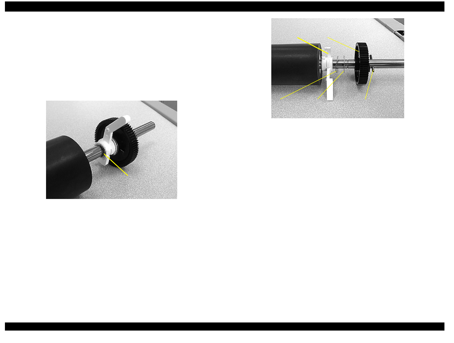
EPSON FX-2180 Service Manual Chapter 4 Disassembly and Assembly
4-12
4.2.9 Removing the Platen Gear
1. Remove the printer cover, ribbon cartridge, and platen knob. (See
section 4.2.1.)
2. Remove the print head, ribbon mask, and upper housing assembly.
(See sections 4.2.3, 4.2.6, and 4.2.7.)
3. Remove the platen assembly. (See section 4.2.8.)
4. Remove the retaining ring (C clip) by pushing both sides of it using
needle-nose pliers.
retaining ring
(#638)
Figure 4-16. Removing the Retaining Ring
5. Remove the spring pin (2 x 12) using a pin drive. Then remove the
platen gear (36 mm spur gear).
right
bushing
leaf spring plain
washer
platen gear (36
mm spur gear)
spring pin
(2 × 12)
Figure 4-17. Removing the Platen Gear
4.2.10 Removing the Case Open Sensor Assembly
1. Remove the printer cover, rear edge guide assembly, paper eject
assembly, and rear tractor unit. (See section 4.2.1.)
2. Remove the panel board assembly. (See section 4.2.2.)
3. Remove the upper housing assembly. (See section 4.2.7.)
4. Turn the upper housing assembly over and remove the case open
sensor assembly by loosening the CBB screw (3 × 8) securing the
sensor holder to the upper housing assembly.
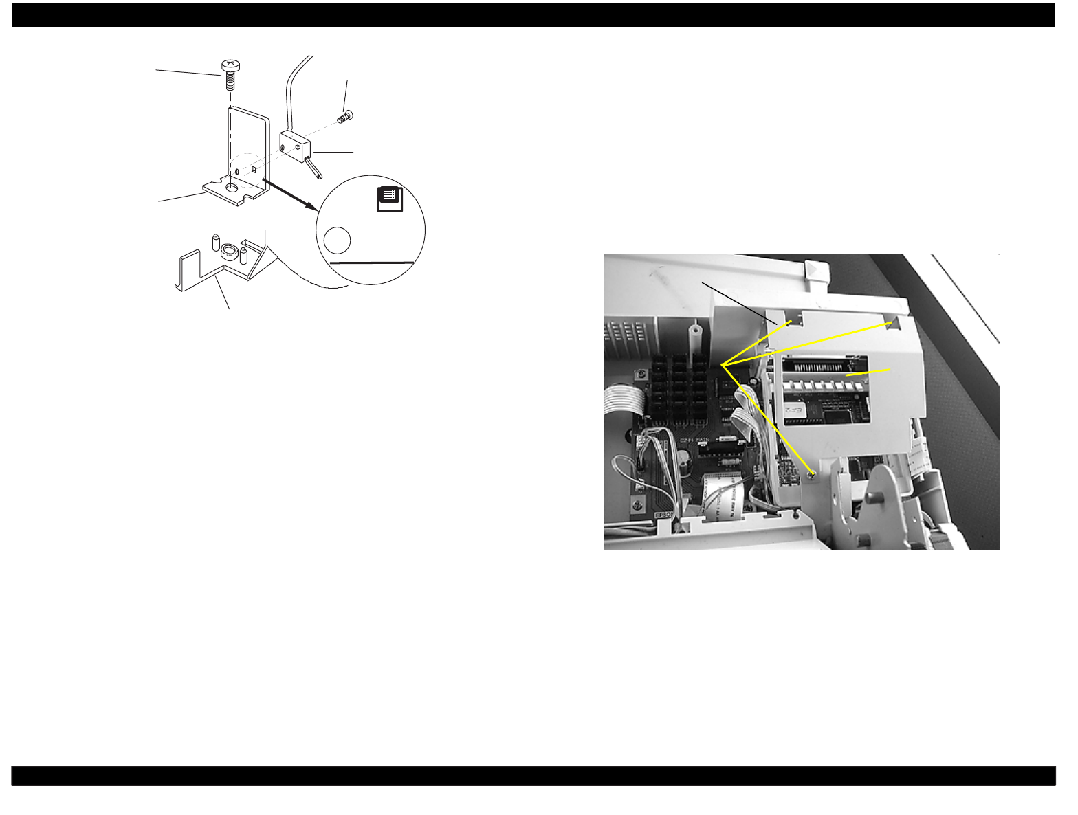
EPSON FX-2180 Service Manual Chapter 4 Disassembly and Assembly
4-13
CBB screw
(3 x 8 )
CB screw
(2 x 8 )
sensor
holder
case open
sensor assem bly
upper housing assem bly
Figure 4-18. Removing the Case Open Sensor Assembly
4.2.11 Removing the Printer Mechanism
1. Remove the printer cover, front and rear edge guide assemblies, front
cover, paper eject assembly, and rear tractor unit. (See section 4.2.1.)
2. Remove the panel board assembly. (See section 4.2.2.)
3. Remove the upper housing assembly. (See section 4.2.7.)
4. Remove the three CBS screws (3 × 4) securing the upper shield plate
to the printer mechanism and remove the upper shield plate. Then
remove the upper I/F grounding plate from the main board assembly.
CBS screws
(3 × 4)
upper shield
plate
upper I/F
grounding plate
Figure 4-19. Removing the Upper Shield Plate and Upper I/F
Grounding Plate
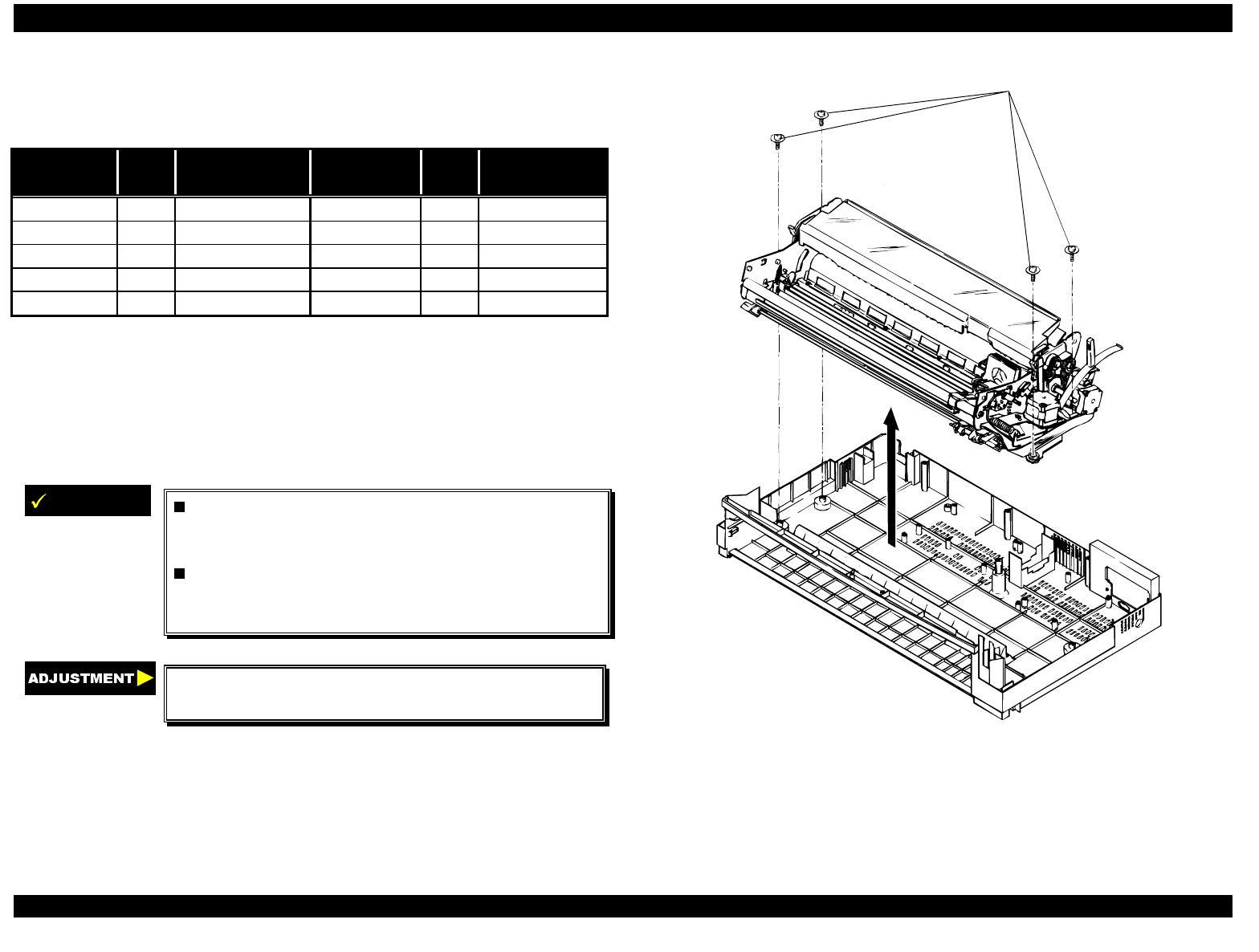
EPSON FX-2180 Service Manual Chapter 4 Disassembly and Assembly
4-14
5. Disconnect the cables from the following connectors on the main
board assembly.
Table 4-6. Main Board Connectors
Connector
Number Pins Connector
Color Connector
Number Pins Connector
Color
CN4 3 white CN5 3 black
CN6 2 white CN7 4 gray
CN8 18 gray CN9 16 gray
CN10 4 white CN11 5 white
CN12 4 white CN13 4 black
Note: To disconnect the cables from CN10 and CN11, pull up the
connector locks.
6. As shown in Figure 4-20, remove the four printer mechanism
mounting screws securing the printer mechanism.
7. Remove the printer mechanism.
IMPORTANT
When you connect the cables to CN10 and
CN11, align the red line in the cable with pin 1
of the connector.
The tightening torque for the four printer
mechanism mounting screws is 0.78 - 0.98 Nm
(10 - 12 Kgf-cm).
Adjust the bidirectional print alignment and reset
the TPE level. (See Chapter 5.)
printer mechanism mounting screws
Figure 4-20. Removing the Printer Mechanism
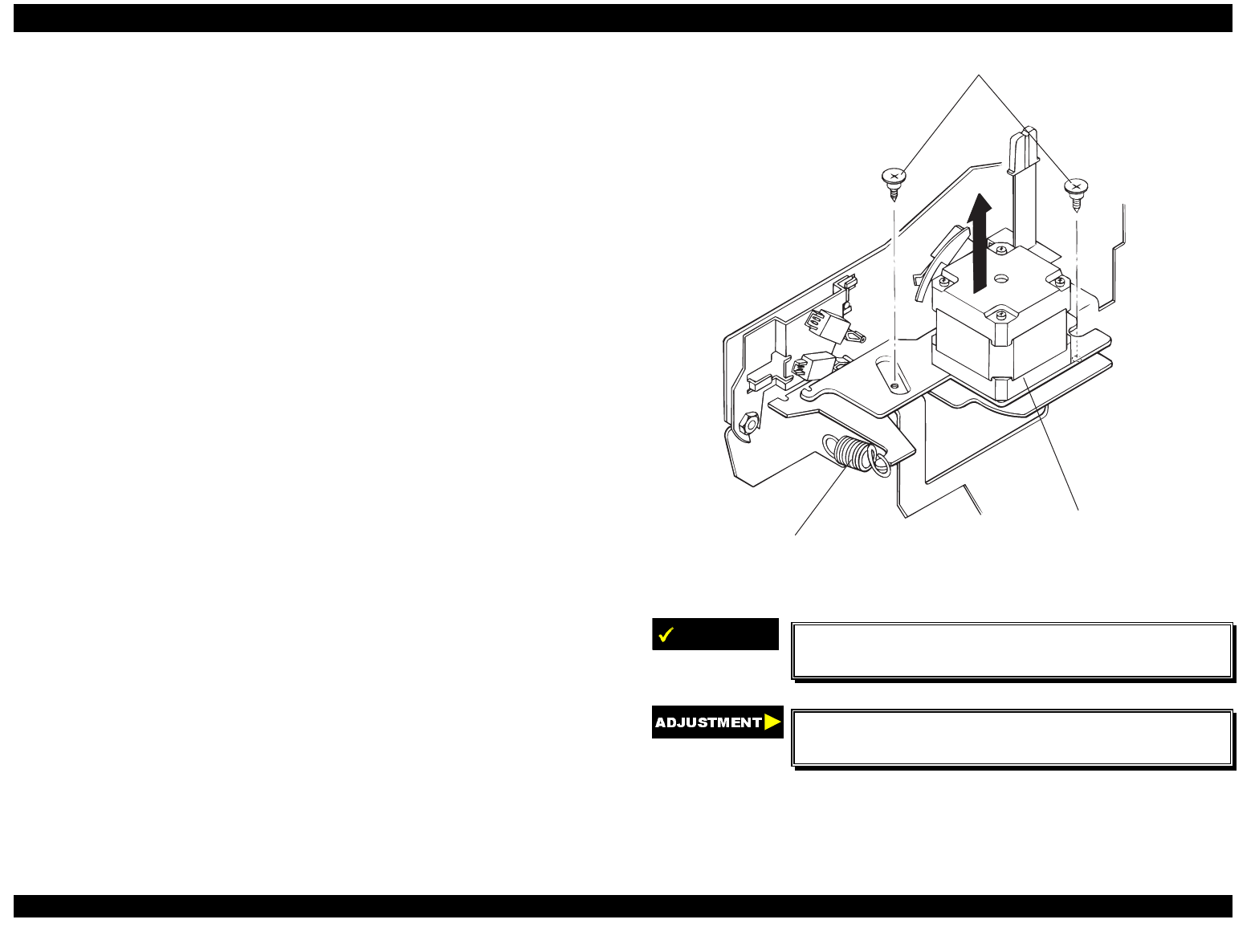
EPSON FX-2180 Service Manual Chapter 4 Disassembly and Assembly
4-15
4.2.11.1 Removing the CR Motor Assembly
1. Remove the printer cover, rear edge guide assembly, paper eject
assembly, and rear tractor unit. (See section 4.2.1.)
2. Remove the panel board assembly. (See section 4.2.2.)
3. Remove the upper housing assembly. (See section 4.2.7.)
4. Remove the printer mechanism. (See section 4.2.11.)
5. Release the extension spring (15.7 g) and then disengage the timing
belt from the CR motor assembly.
6. Remove the two screws securing the CR motor assembly.
7. Remove the CR motor assembly from the printer mechanism.
C R m ounting screw s
extension spring (15.7 g)
CR motor assembly
Figure 4-21. Removing the CR Motor Assembly
IMPORTANT
The tightening torque for the two CR mounting
screws is 0.78 - 0.98 Nm (8 - 10 Kgf-cm).
Adjust the bidirectional print alignment and reset
the TPE level. (See Chapter 5.)
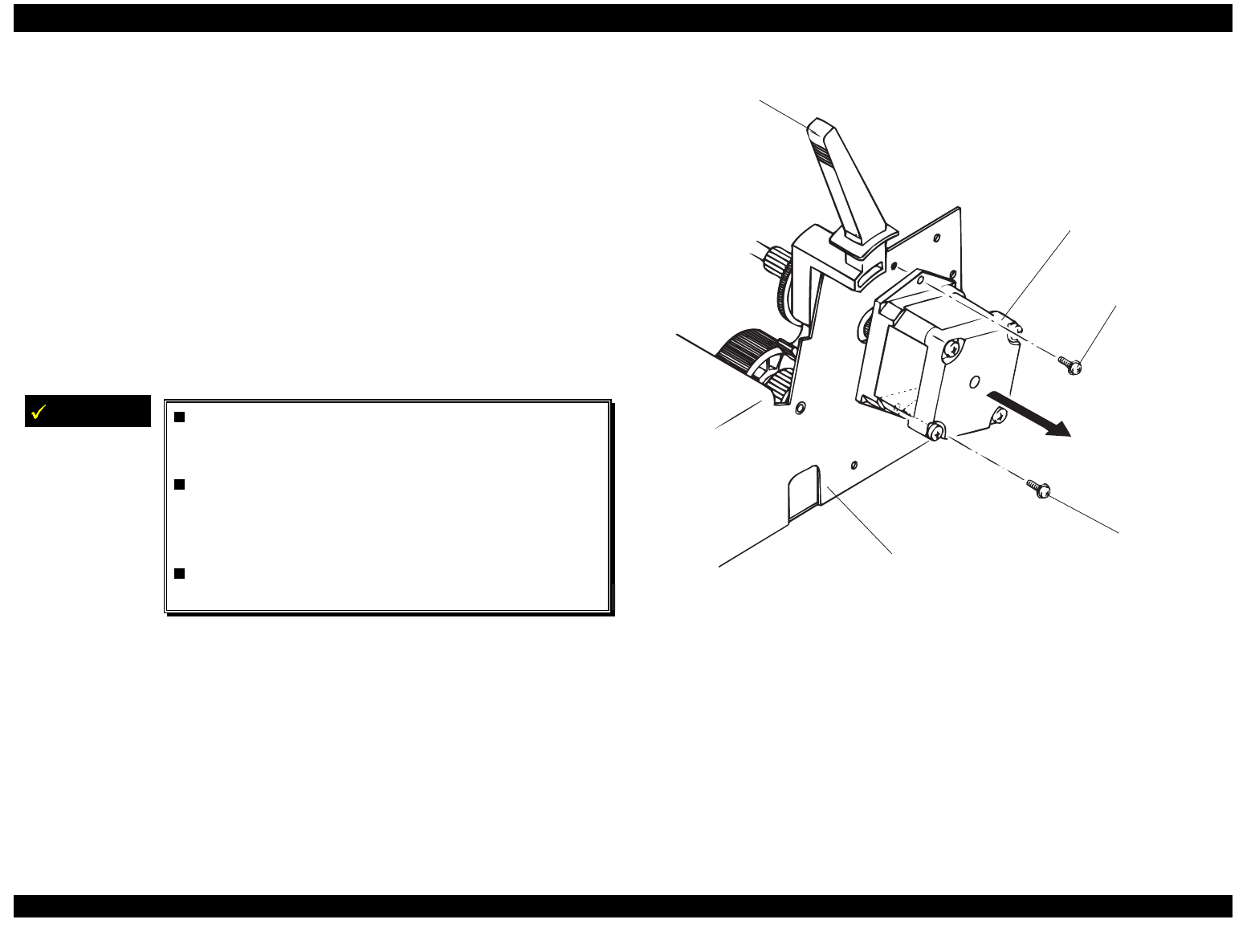
EPSON FX-2180 Service Manual Chapter 4 Disassembly and Assembly
4-16
4.2.11.2 Removing the PF Motor Assembly
1. Remove the printer cover, front and rear edge guide assemblies, front
cover, paper eject assembly, and front and rear tractor units. (See
section 4.2.1.)
2. Remove the panel board assembly. (See section 4.2.2.)
3. Remove the upper housing assembly. (See section 4.2.7.)
4. Remove the printer mechanism. (See section 4.2.11.)
5. Move the paper release lever to the pull tractor position.
6. Remove the CBS screw (3 × 6) and the CB screw (3 × 8) securing the
PF motor to the right sub frame.
7. Remove the PF motor from the right sub frame.
IMPORTANT
Before attaching the PF motor to the right sub
frame, set the paper release lever to the pull
tractor position (full release position).
The CB screw (3 ×× 8) is used to secure the
upper part of the PF motor. The CBS screw
(3 ×× 6) is used to secure the lower part of the PF
motor.
The tightening torque for the CB and CBS
screws is 0.8 - 1.0 Nm (8 - 10 Kgf-cm).
CB screw (3 x 8)
C B S s c re w (3 x 6 )
P F m o to r
right sub fram e
paper release lever
Figure 4-22. Removing the PF Motor
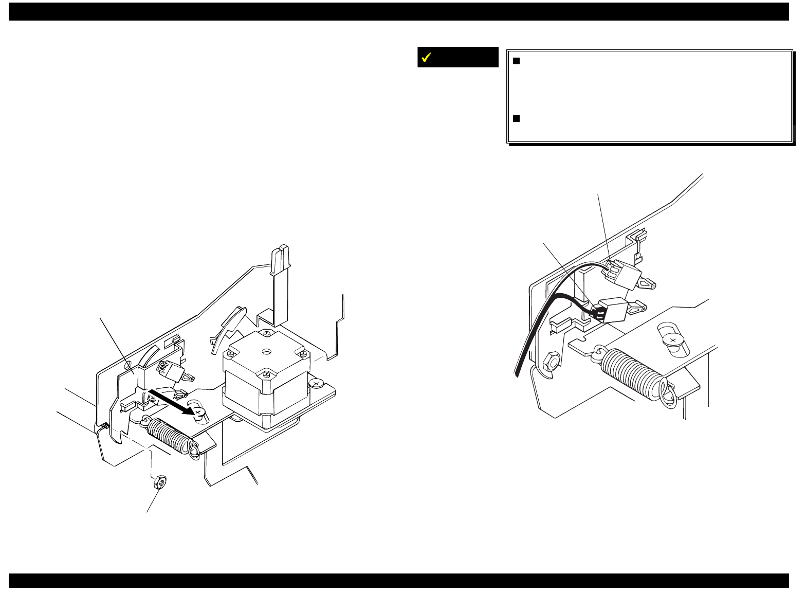
EPSON FX-2180 Service Manual Chapter 4 Disassembly and Assembly
4-17
4.2.11.3 Removing the PG Sensor Assembly
1. Remove the printer cover, front and rear edge guide assemblies, front
cover, paper eject assembly, and front and rear tractor units. (See
section 4.2.1.)
2. Remove the panel board assembly. (See section 4.2.2.)
3. Remove the upper housing assembly. (See section 4.2.7.)
4. Remove the printer mechanism. (See section 4.2.11.)
5. Loosen but do not remove the hexagonal nut (M4) securing the PG
sensor assembly to the right frame assembly.
6. Remove the PG sensor assembly from the right frame assembly.
hexagonal nut
PG sensor assembly
Figure 4-23. Removing the PG Sensor Assembly
IMPORTANT
When you connect the PG sensors to the PG
sensor holder, make sure the sensor with the
white connector is in the upper position, as
shown in Figure 4-24.
The tightening torque for the hexagonal nut is
1.18 - 1.37 Nm (12 - 14 Kgf-cm).
PG SW 1
(w hite connector)
PG SW 2
(black connector)
Figure 4-24. Connecting the PG Sensors to the PG Sensor Holder
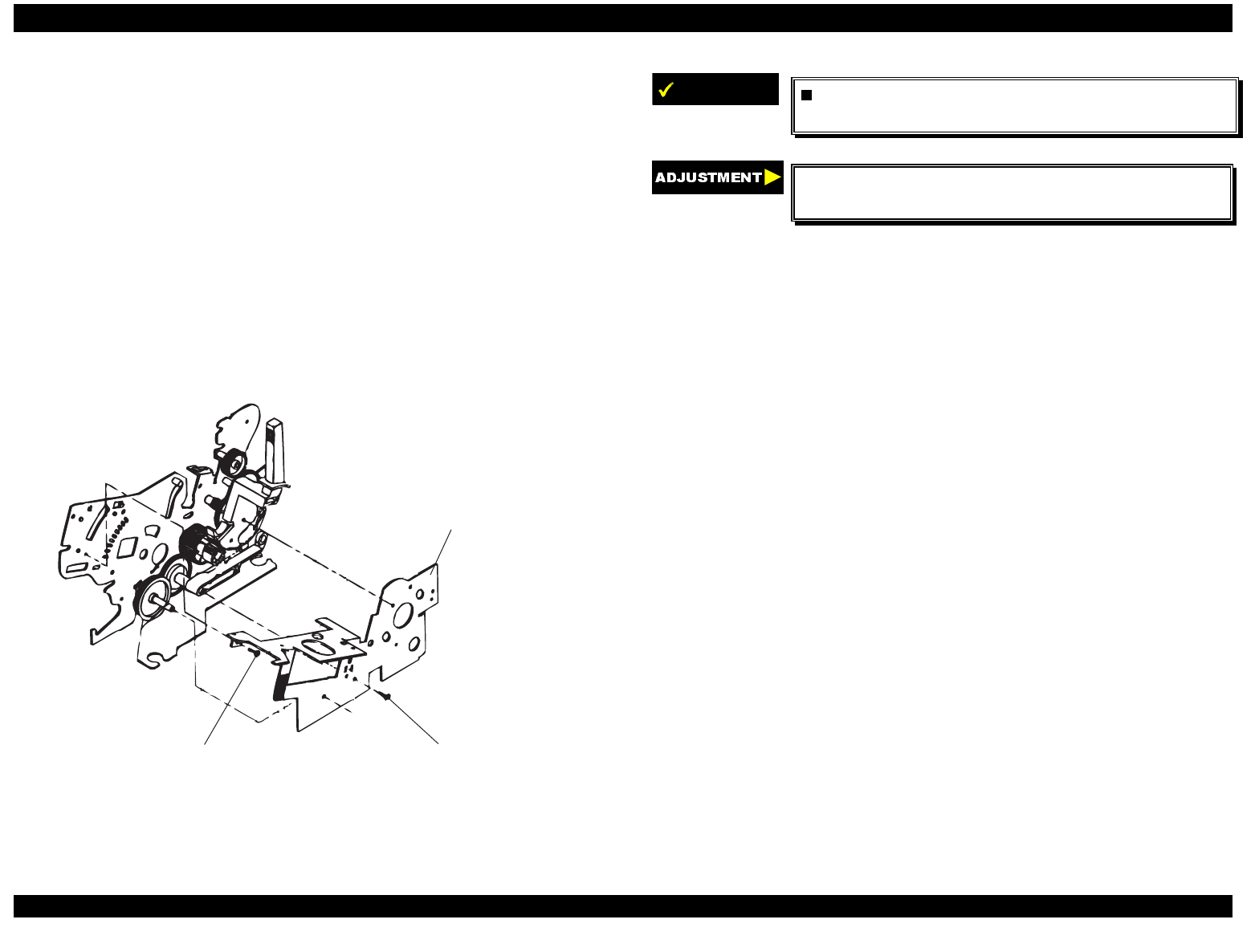
EPSON FX-2180 Service Manual Chapter 4 Disassembly and Assembly
4-18
4.2.11.4 Removing the Right Sub Frame Assembly
1. Remove the printer cover, front and rear edge guide assemblies, front
cover, paper eject assembly, and front and rear tractor units. (See
section 4.2.1.)
2. Remove the panel board assembly. (See section 4.2.2.)
3. Remove the upper housing assembly. (See section 4.2.7.)
4. Remove the printer mechanism. (See section 4.2.11.)
5. Remove the PF motor assembly. (See section 4.2.11.2.)
6. Remove the two CBS screws (3 × 6 and 3 × 8) securing the right sub
frame.
7. Remove the right sub frame from the right frame.
right sub fram e
CBS screw (3 x 6) CBS screw (3 x 8)
Figure 4-25. Removing the Right Sub Frame
IMPORTANT
The tightening torque for the CBS screws (3 ×× 6
and 3 ×× 8) is 0.78 - 0.98 Nm (8 - 10 Kgf-cm).
Adjust the bidirectional print alignment. (See
Chapter 5.)
4.2.11.5 Removing the Right Frame Assembly
1. Remove the printer cover, front and rear edge guide assemblies, front
cover, paper eject assembly, and front and rear tractor units. (See
section 4.2.1.)
2. Remove the panel board assembly. (See section 4.2.2.)
3. Remove the upper housing assembly. (See section 4.2.7.)
4. Remove the printer mechanism. (See section 4.2.11.)
5. Remove the platen assembly. (See section 4.2.8.)
6. Remove the PG sensor assembly. (See section 4.2.11.3.)
7. Remove the right sub frame assembly. (See section 4.2.11.4.)
8. Remove the hexagonal nut (M4) securing the gap adjust lever. Then
remove the lever from the right frame assembly.
9. Remove the CBS screw (3 × 6) securing the platen cover to the right
frame assembly.
10. Remove the two CBS screws (3 × 6) securing the right frame
assembly at the positions shown in Figure 4-26.
11. Remove the right frame assembly.
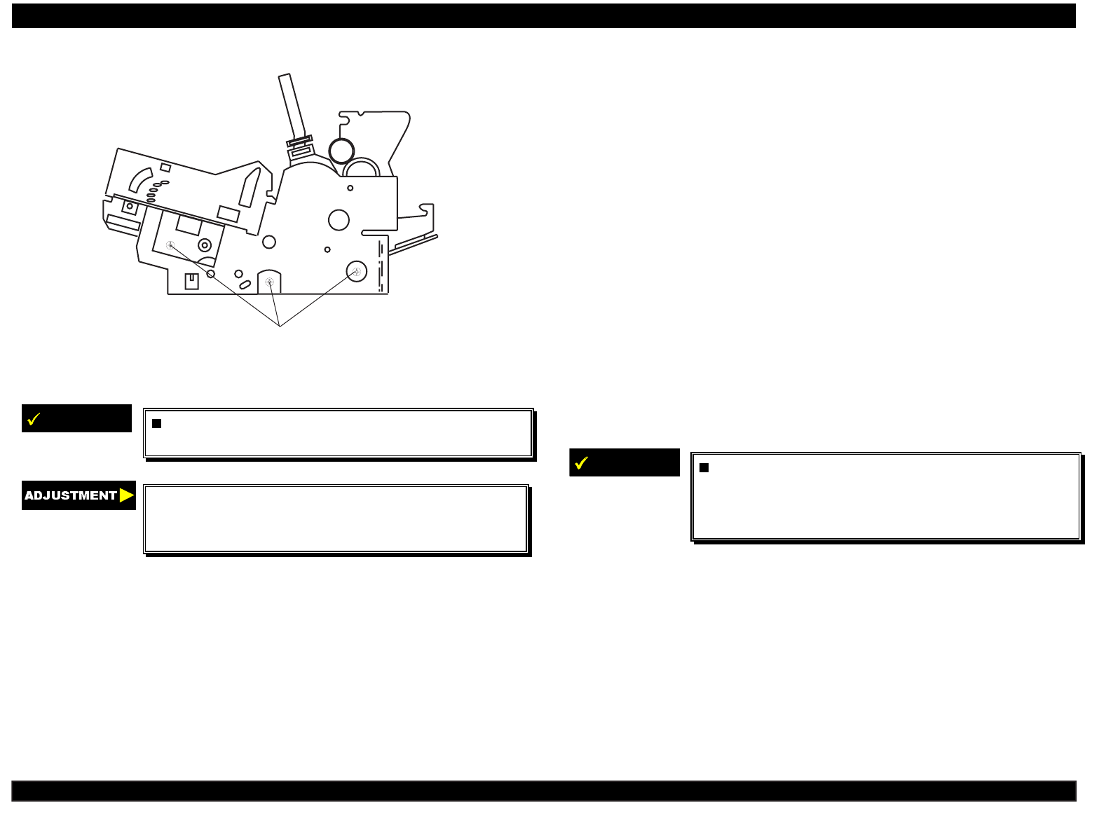
EPSON FX-2180 Service Manual Chapter 4 Disassembly and Assembly
4-19
C B S screw s (3 x 6)
Figure 4-26. Removing the Right Frame Assembly
IMPORTANT
The tightening torque for the hexagonal nut is
1.18 - 1.37 Nm (12 - 14 Kgf-cm).
Adjust the platen gap/parallelism and
bidirectional print alignment, and reset the TPE
level. (See Chapter 5.)
4.2.11.6 Disassembling the Right Frame Assembly
1. Remove the printer cover, front and rear edge guide assemblies, front
cover, paper eject assembly, and front and rear tractor units. (See
section 4.2.1.)
2. Remove the panel board assembly. (See section 4.2.2.)
3. Remove the upper housing assembly. (See section 4.2.7.)
4. Remove the printer mechanism. (See section 4.2.11.)
5. Remove the PF motor assembly. (See section 4.2.11.2.)
6. Remove the right sub frame assembly. (See section 4.2.11.4.)
7. Remove the right frame assembly. (See section 4.2.11.5.)
8. Remove the following 11 parts from the right frame assembly:
2 compression springs (200 g) 2 plain washers
2 spur gears (34.5 mm) 1 spur gear (34 mm)
1 spur gear (27 mm) 1 spur gear (21 mm)
1 combination gear (8 mm, 31.5 mm) 1 intermittent gear
IMPORTANT
When assembling the right frame assembly,
attach the 11 parts listed in step 8 to the right
frame assembly as shown in the following
figures.
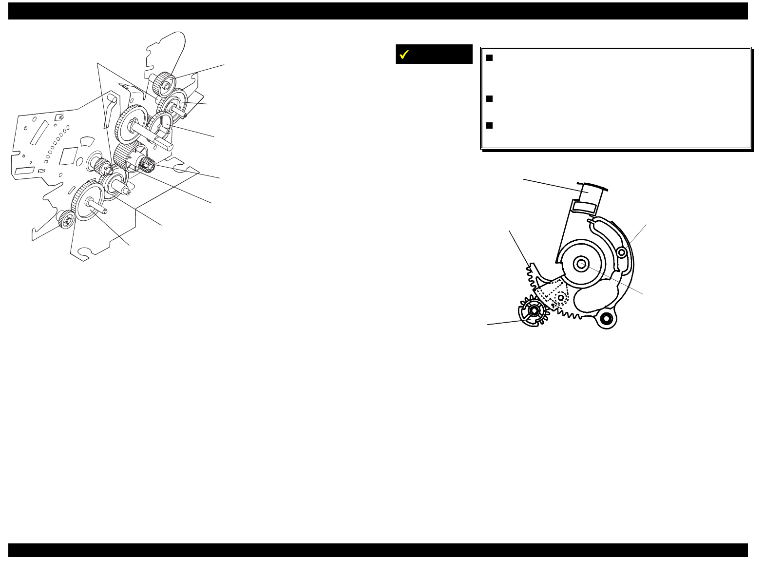
EPSON FX-2180 Service Manual Chapter 4 Disassembly and Assembly
4-20
2 com pression springs
(200 g) and
2 plain w ashers
spur gear (34.5 m m )
spur gear (21 m m )
spur gear (34.5 m m )
com bination gear (8 m m , 31.5 m m )
interm ittent gear
spur gear (27 m m )
spur gear (34 m m )
Figure 4-27. Engaging the Right Frame Assembly Gears (1 of 2)
IMPORTANT
Engage the intermittent gear, release lever,
and release lever transmission as shown in
Figure 4-28.
Engage the release lever and release lever
transmission with the tractor clutch cam.
Attach the tractor clutch cam as shown in
Figure 4-29.
release lever
release lever transmission
intermittent gear
top end of release
lever shaft
top end of spur
gear (34.5 mm)
Figure 4-28. Engaging the Right Frame Assembly Gears (2 of 2)
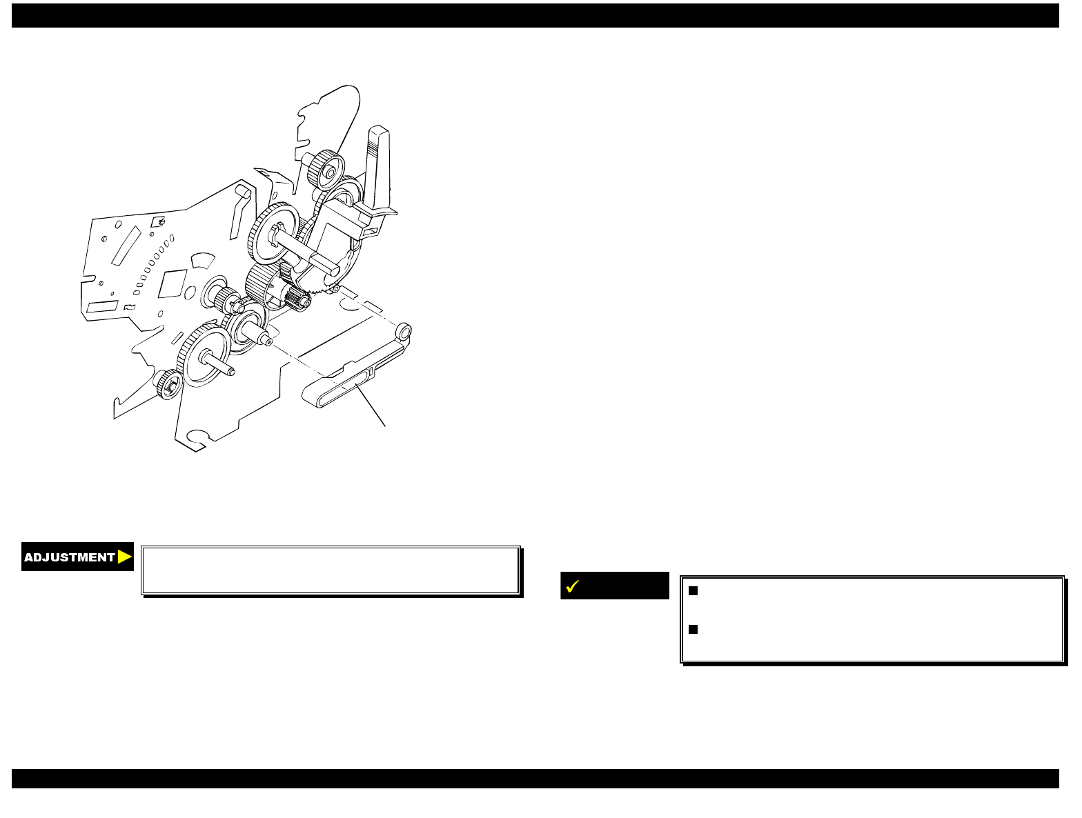
EPSON FX-2180 Service Manual Chapter 4 Disassembly and Assembly
4-21
tractor clutch cam
Figure 4-29. Engaging the Tractor Clutch Cam
Adjust the bidirectional print alignment. (See
Chapter 5.)
4.2.11.7 Removing the Left Frame Assembly
1. Remove the printer cover, front and rear edge guide assemblies, front
cover, paper eject assembly, and front and rear tractor units. (See
section 4.2.1.)
2. Remove the panel board assembly. (See section 4.2.2.)
3. Remove the upper housing assembly. (See section 4.2.7.)
4. Remove the printer mechanism. (See section 4.2.11.)
5. Disconnect the cable connector from the release lever sensor, and
then disconnect the cable connector from the HP sensor.
6. Remove the print head and the ribbon mask holder. (See sections
4.2.3 and 4.2.6.)
7. Remove the platen assembly. (See section 4.2.8.)
8. Remove the CBS screw (3 × 6) securing the platen cover to the left
frame assembly.
9. Loosen the hexagonal nut (M4) securing the CR guide shaft and left
frame.
10. Remove the parallelism adjustment bushing.
11. Remove the four CBS screws (3 × 6) securing the left frame
assembly.
12. Remove the left frame assembly.
IMPORTANT
The tightening torque for the CBS screws (3 ×× 6)
is 0.78 - 0.98 Nm (8 - 10 Kgf-cm).
The tightening torque for the hexagonal nut is
1.18 - 1.37 Nm (12 - 14 Kgf-cm).
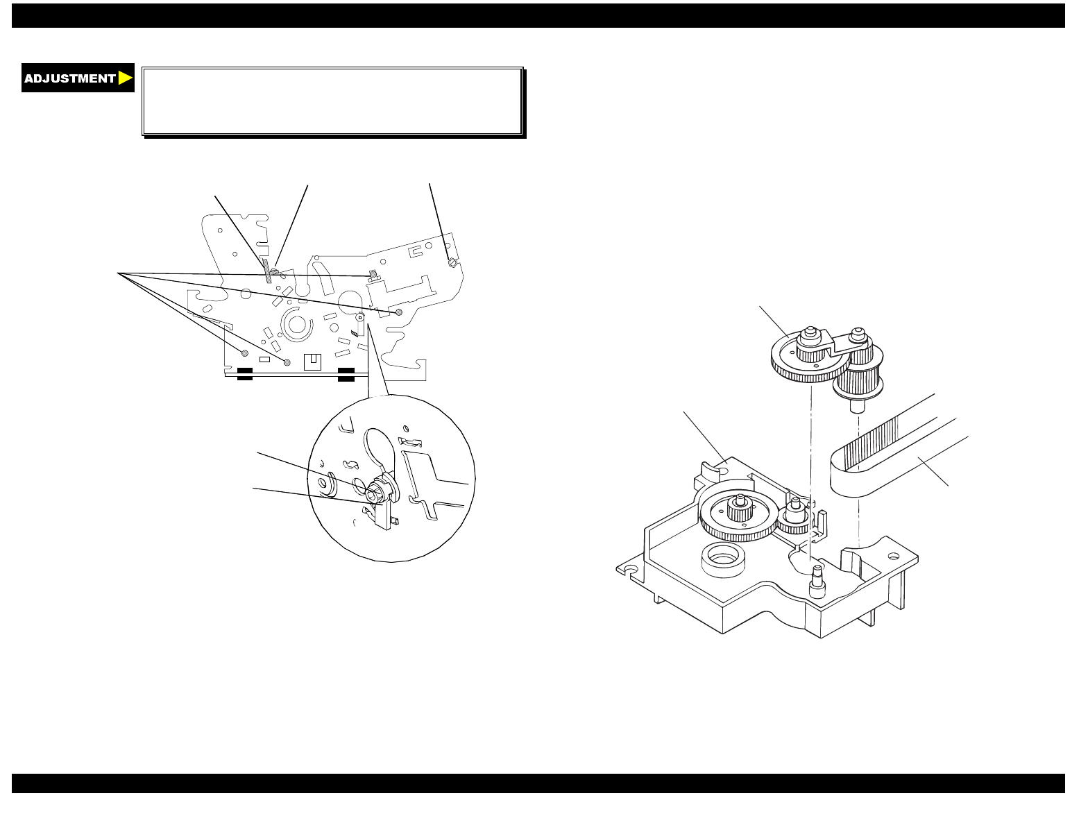
EPSON FX-2180 Service Manual Chapter 4 Disassembly and Assembly
4-22
Adjust the platen gap/parallelism and
bidirectional print alignment, and reset
the TPE level. (See Chapter 5.)
CBS screws (3 × 6)
securin
g
the left frame
hexa
g
onal nut (M4)
platen cover CBS screw (3 × 6)
parallelism adjustment bushin
g
hexa
g
onal nut
Figure 4-30. Removing the Left Frame Assembly
4.2.11.8 Removing the Ribbon Drive (RD) Assembly
1. Remove the printer cover, front and rear edge guide assemblies, front
cover, paper eject assembly, and front and rear tractor units. (See
section 4.2.1.)
2. Remove the panel board assembly. (See section 4.2.2.)
3. Remove the upper housing assembly. (See section 4.2.7.)
4. Remove the printer mechanism. (See section 4.2.11.)
5. Remove the CR motor tension spring and disengage the timing belt
from the CR motor pinion gear. (See section 4.2.11.1.)
6. Remove the left frame assembly. (See section 4.2.11.7.)
7. Remove the two CBS screws (3 × 8) securing the RD assembly to the
front frame.
8. Remove the RD assembly from the front frame.
9. Remove the timing belt from the RD assembly.
driven pulley assem bly
RD assembly
tim ing belt
Figure 4-31. Removing the RD Assembly
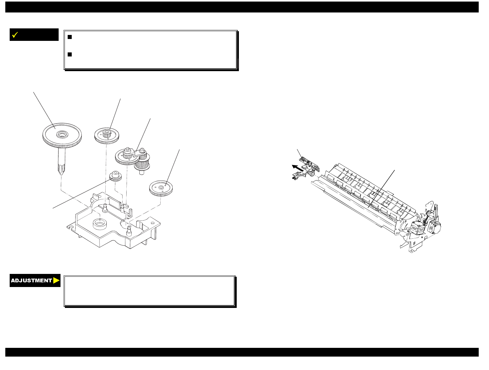
EPSON FX-2180 Service Manual Chapter 4 Disassembly and Assembly
4-23
IMPORTANT
The tightening torque for the two CBS screws
(3 ×× 8) is 0.78 - 0.98 Nm (8 - 10 Kgf-cm).
Engage the RD assembly gears as shown in
Figure 4-32.
RD rachet com bination gear (7 m m , 23 m m )
driven pulley assem bly
spur gear (25 m m )
spur gear (11 m m )
Figure 4-32. Engaging the RD Assembly Gears
Adjust the platen gap/parallelism and
bidirectional print alignment, and reset the TPE
level. (See Chapter 5.)
4.2.11.9 Removing the CR Assembly
1. Remove the printer cover, front and rear edge guide assemblies, front
cover, paper eject assembly, and front and rear tractor units. (See
section 4.2.1.)
2. Remove the panel board assembly. (See section 4.2.2.)
3. Remove the upper housing assembly. (See section 4.2.7.)
4. Remove the printer mechanism. (See section 4.2.11.)
5. Remove the left frame assembly. (See section 4.2.11.7.)
6. Remove the RD assembly. (See section 4.2.11.8.)
7. Remove the CR assembly from the front and rear CR guide shafts.
CR assembly
rear CR guide shaft
Figure 4-33. Removing the CR Assembly
8. Remove the CR assembly.
9. Remove the timing belt from the two holding slots under the CR
assembly.
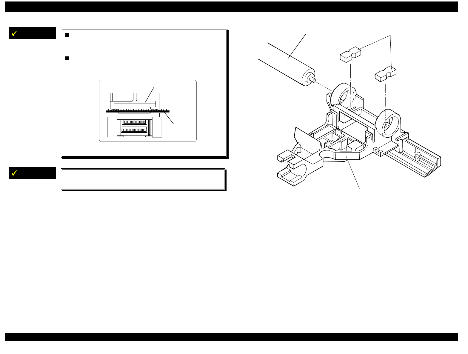
EPSON FX-2180 Service Manual Chapter 4 Disassembly and Assembly
4-24
IMPORTANT
When installing the CR assembly, insert the
timing belt securely into the two holding slots
at the bottom of the CR assembly.
Make sure you take up all the slack in the
timing belt between the two slots, as shown
below.
timing belt
CR assembly
Figure 4-34. Inserting the Timing Belt
IMPORTANT
Insert the two oil pads into the proper positions in
the CR assembly, as shown in Figure 4-35.
oil pads
CR assembl
y
rear CR
g
uide shaft
Figure 4-35. Installing the Oil Pads in the CR Assembly
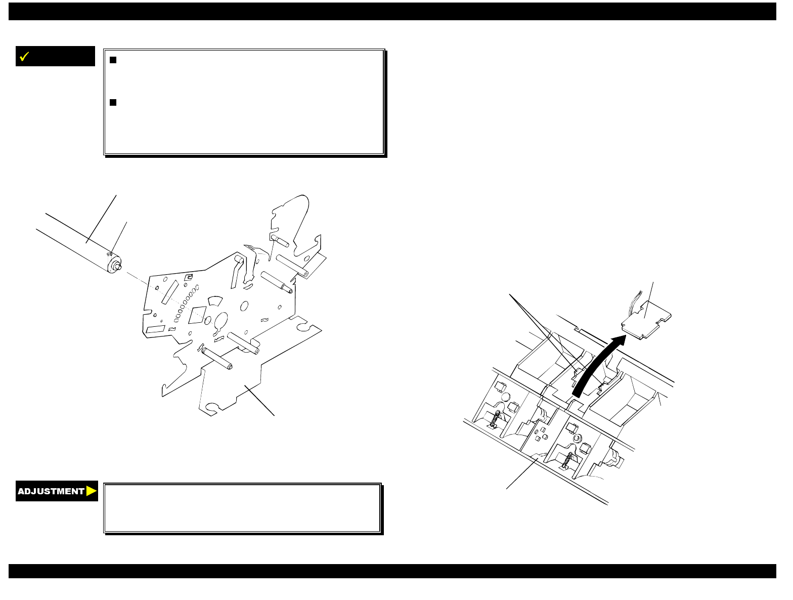
EPSON FX-2180 Service Manual Chapter 4 Disassembly and Assembly
4-25
IMPORTANT
If you remove the rear CR guide shaft along
with the CR assembly, be sure to reinstall the
rear CR guide shaft in the printer mechanism.
The rear CR guide shaft has a hole near the
right edge. One side of the hole has a
chamfered edge; this side of the hole
should face up, as shown in Figure 4-36.
left frame assembl
y
chamfered hole
CR
g
uide shaft
Figure 4-36. Installing the Rear CR Guide Shaft
Adjust the platen gap/parallelism and
bidirectional print alignment, and reset the TPE
level. (See Chapter 5.)
4.2.11.10 Removing the Rear PE Sensor Assembly
1. Remove the printer cover, front and rear edge guide assemblies, front
cover, paper eject assembly, and front and rear tractor units. (See
section 4.2.1.)
2. Remove the panel board assembly. (See section 4.2.2.)
3. Remove the upper housing assembly. (See section 4.2.7.)
4. Remove the printer mechanism. (See section 4.2.11.)
5. Turn the printer over, and insert a standard screwdriver or other prying
tool into the hole in the rear frame.
6. Release the two clips while pushing up the rear PE sensor with the
screwdriver or other prying tool. See Figure 4-37.
7. Disconnect the rear PE sensor connector and then remove the rear
PE sensor assembly.
clips rear PE sensor assembly
rear frame
Figure 4-37. Removing the Rear PE Sensor Assembly
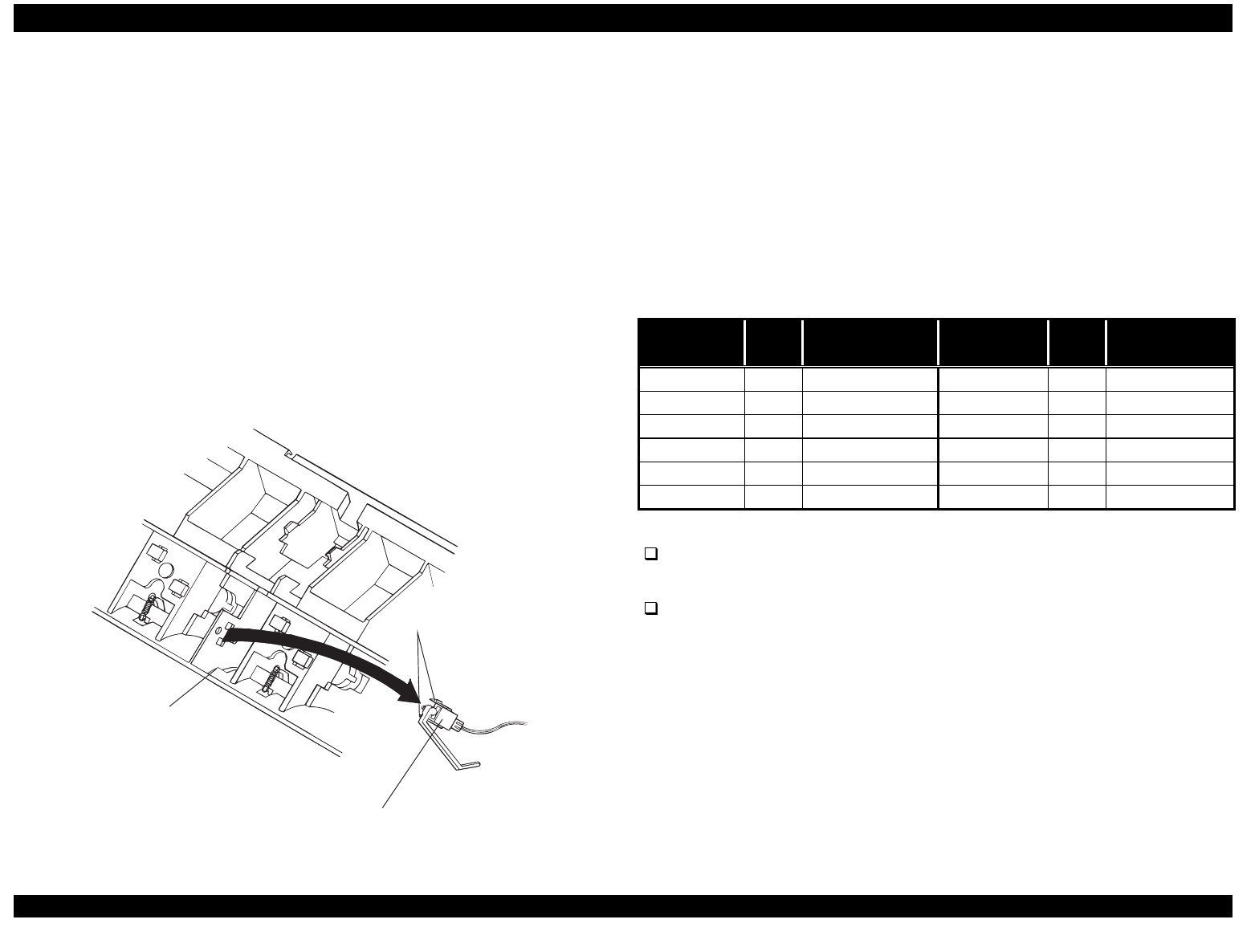
EPSON FX-2180 Service Manual Chapter 4 Disassembly and Assembly
4-26
4.2.11.11 Removing the Front PE Sensor Assembly
1. Remove the printer cover, front and rear edge guide assemblies, front
cover, paper eject assembly, and front and rear tractor units. (See
section 4.2.1.)
2. Remove the panel board assembly. (See section 4.2.2.)
3. Remove the upper housing assembly. (See section 4.2.7.)
4. Remove the printer mechanism. (See section 4.2.11.)
5. Turn the printer over, and insert a standard screwdriver or other prying
tool into the hole in the rear frame.
6. Release the two clips while pushing up the front PE sensor with the
screwdriver or other prying tool. See Figure 4-38.
7. Disconnect the front PE sensor connector and then remove the front
PE sensor assembly.
clips
front P E sensor assem bly
re a r fra m e
Figure 4-38. Removing the Front PE Sensor Assembly
4.2.11.12 Removing the Main Board Assembly
1. Remove the printer cover, front and rear edge guide assemblies, front
cover, paper eject assembly, and front and rear tractor units. (See
section 4.2.1.)
2. Remove the panel board assembly. (See section 4.2.2.)
3. Remove the upper housing assembly. (See section 4.2.7.)
4. Disconnect the cables from the following connectors on the main
board assembly.
Table 4-7. Main Board Connectors
Connector
Number Pins Connector
Color Connector
Number Pins Connector
Color
CN3 10 white CN4 3 white
CN5 3 black CN6 2 white
CN7 4 gray CN8 18 gray
CN9 16 gray CN10 4 white
CN11 5 white CN12 4 white
CN13 4 black CN15 22 white
Note:
To disconnect the cables from CN10 and CN11, pull up the connector
locks.
To disconnect the cable from CN3, push down on the connector
cover.
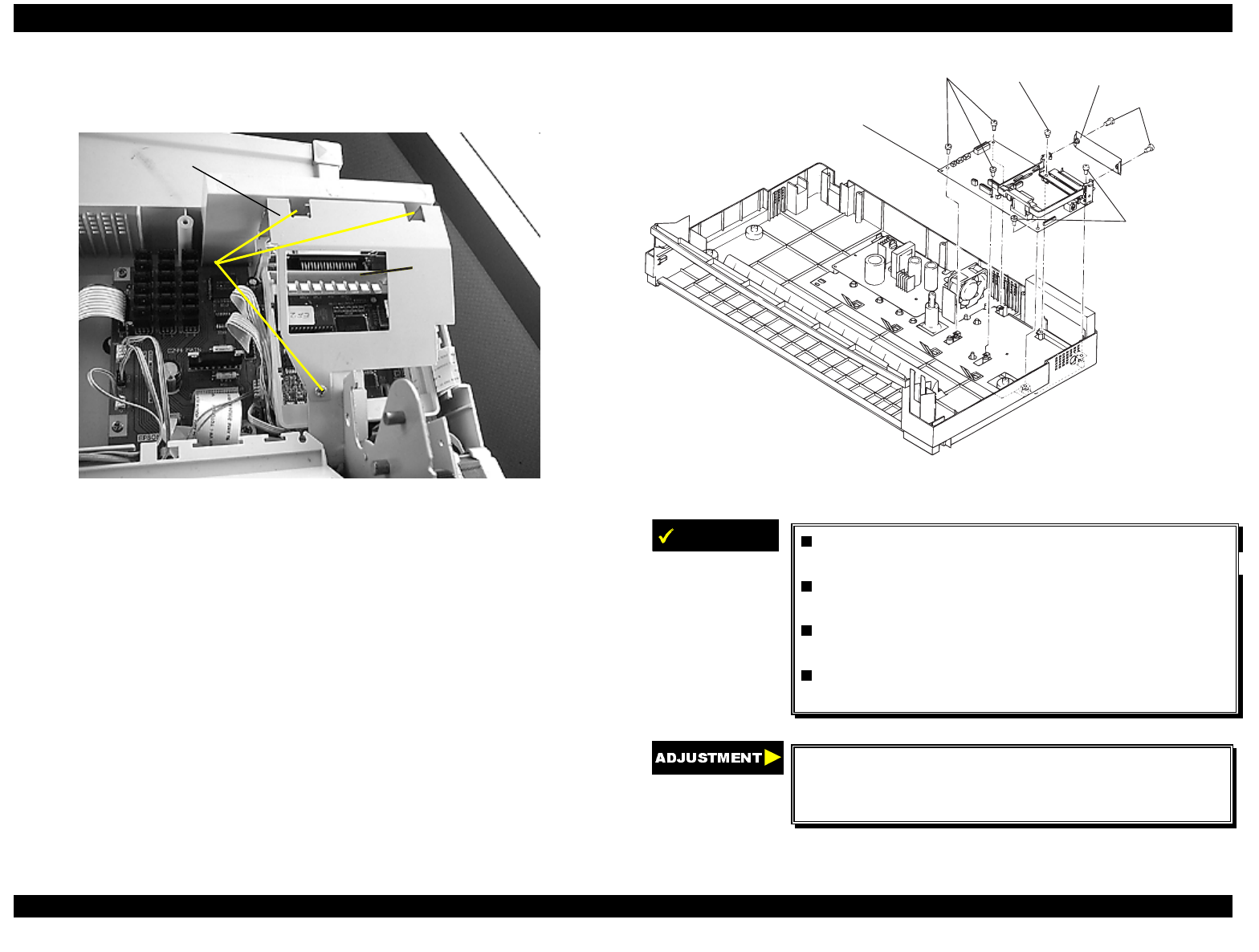
EPSON FX-2180 Service Manual Chapter 4 Disassembly and Assembly
4-27
5. Remove the three CBS screws (3 × 4) securing the upper shield plate
to the printer mechanism and remove the upper shield plate. Then
remove the upper I/F grounding plate from the main board assembly.
CBS screws
(3 × 4)
upper shield
plate
upper I/F
grounding plate
Figure 4-39. Removing the Upper Shield Plate and Upper I/F
Grounding Plate
6. Remove the two CBS screws (3 × 12) securing the upper connector
cover.
7. Remove the five CBB screws (3 × 12) and one CBC lamitite screw
(3 × 8) securing the main board assembly to the lower housing
assembly.
8. Remove the optional I/F cage from the main board by releasing the
hooks that secure it to the main board.
9. Remove the main board assembly with the upper I/F grounding plate.
CBS screws
(3 x 12)
CBB screws
(3 x 12)
CBC screw
(3 x 8 )
CBB screws
(3 x 12)
upper connector cover
m ain board assem bly
Figure 4-40. Removing the Main Board Assembly
IMPORTANT
Insert the CBC lamitite screw (3 ×× 8) into the
appropriate screw hole as shown in Figure 4-40.
After you insert the cable connectors into CN10
and CN11, push down each connector’s lock.
The tightening torque for the four CBB screws
(3 ×× 12) is 0.78 - 0.98 Nm (8 - 10 Kgf-cm).
The tightening torque for the CBC screw (3 ×× 8)
is 0.78 - 0.98 Nm (8 - 10 Kgf-cm).
If you replace the main board, adjust the
bidirectional print alignment, reset the factory
settings, and reset the TPE level. (See Chapter 5.)
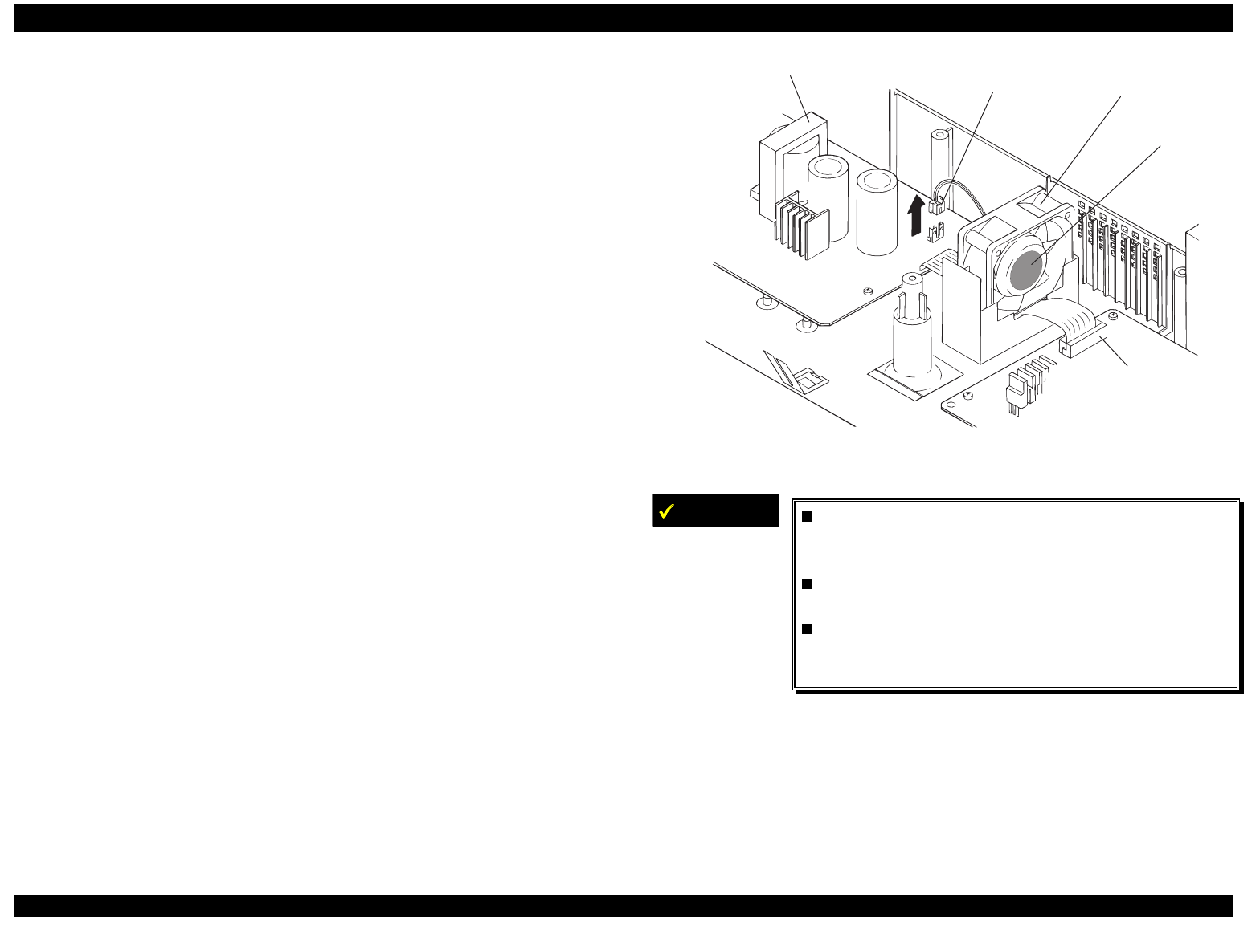
EPSON FX-2180 Service Manual Chapter 4 Disassembly and Assembly
4-28
4.2.11.13 Removing the Power Supply Board Assembly
1. Remove the printer cover, front and rear edge guide assemblies, front
cover, paper eject assembly, and front and rear tractor units. (See
section 4.2.1.)
2. Remove the panel board assembly. (See section 4.2.2.)
3. Remove the upper housing assembly. (See section 4.2.7.)
4. Disconnect the cable from CN3 on the main board assembly.
5. Disconnect the cable for the fan motor from CN3 on the power supply
board assembly. Then remove the fan motor.
6. Remove the five CBB screws (3 × 12) securing the power supply
board assembly.
7. Remove the power supply board assembly.
fan m otor
CN3 (power
supply)
pow er supply board assem bly
label side
m ain board
C N 3 (m ain board)
Figure 4-41. Removing the Power Supply Board Assembly
IMPORTANT
When installing the power supply board
assembly, insert the cable for CN2 on the power
supply board under the fan motor.
The tightening torque for the CBB screws
(3 ×× 12) is 0.78 - 0.98 Nm (8 - 10 Kgf-cm).
Install the fan motor so that the label side of
the fan faces the main board assembly. (See
Figure 4-41 above.)

ADJUSTMENTS
&+$37(5
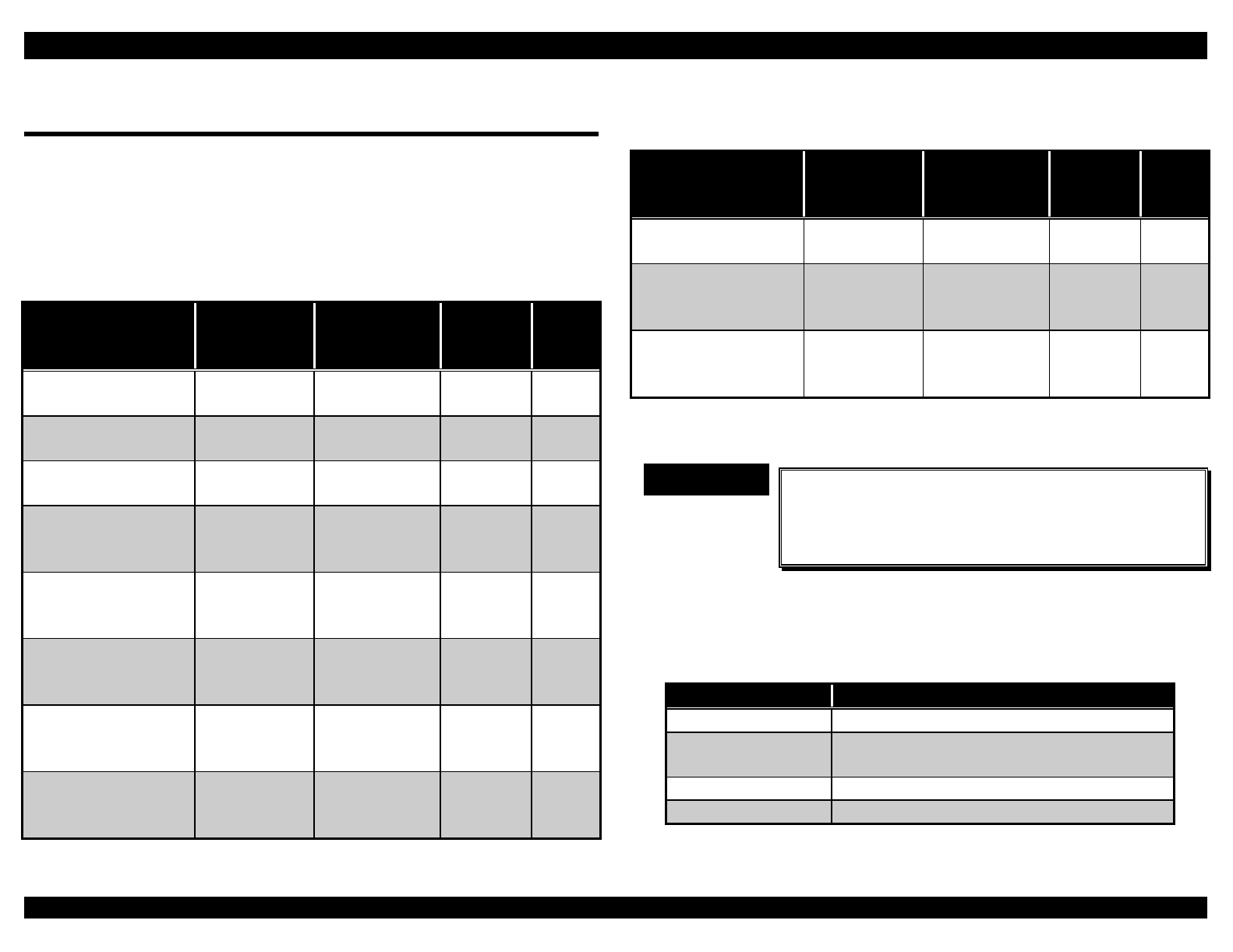
EPSON FX-2180 Service Manual Chapter 5 Adjustments
5-1
5.1 Adjustment Overview
5.1.1 Required Adjustments
This chapter describes the adjustments you need to perform after you
remove or replace certain printer parts. The table below indicates which
adjustments are required for each repair procedure.
Table 5-1. Required Adjustments
Repair Procedure/
Adjustment Platen Gap/
Parallelism Bidirectional
Print
Alignment
Factory
Settings TPE
Level
Reset
Printer mechanism
replacement
✔✔
Print head removal
or replacement
✔ ✔ ✔ ✔
Main board
replacement
✔✔✔
PW sensor
assembly
replacement
✔
Platen assembly
removal or
replacement
✔✔
Carriage motor
assembly removal
or replacement
✔✔
Right frame
assembly removal
or replacement
✔✔✔
Right sub frame
assembly removal
or disassembly
✔
Table 5-1. Required Adjustments (Continued)
Repair Procedure/
Adjustment Platen Gap/
Parallelism Bidirectional
Print
Alignment
Factory
Settings TPE
Level
Reset
Left frame removal
or replacement
✔✔✔
RD assembly
removal or
replacement
✔ ✔ ✔
Carriage assembly
removal or
replacement
✔✔✔
✔ Indicates that the adjustment is required.
Indicates that the adjustment is not required.
IMPORTANT
9
When you replace or reassemble any printer part,
use the Check program on the Settings diskette to
print various check patterns and check the
printer’s performance and settings.
5.1.2 Adjustment Tools
The following table lists the tools required for each adjustment.
Table 5-2. Required Adjustment Tools
Adjustment Required Tool
Platen gap Thickness gauge (B776702201)
Bidirectional print
alignment
Settings diskette, Remote utility, or the
printer’s control panel
Factory settings Settings diskette
TPE level reset Settings diskette
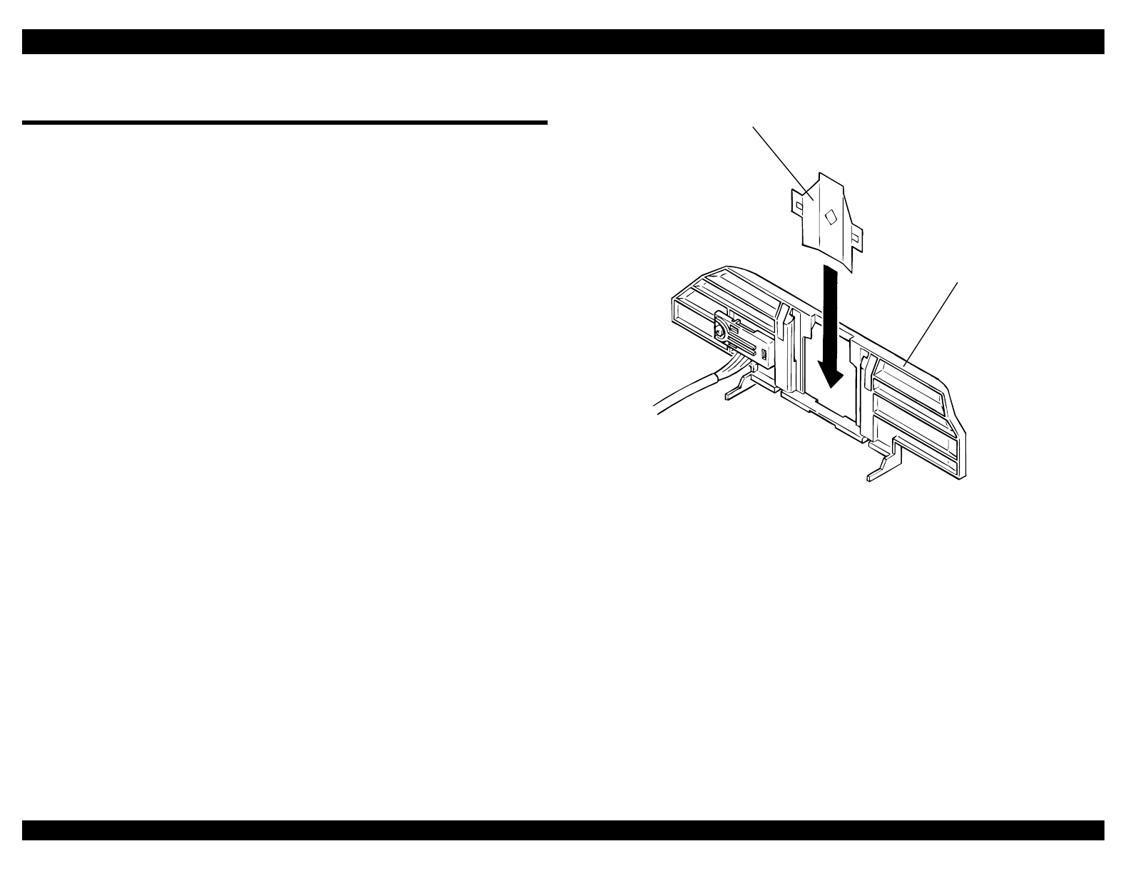
EPSON FX-2180 Service Manual Chapter 5 Adjustments
5-2
5.2 Adjusting and Resetting the Printer
5.2.1 Platen Gap/Parallelism Adjustment
If you have rotated or reassembled the rear carriage guide shaft or
parallelism adjustment bushing, or if printing is too light or too dark even
when the PG lever is in the proper position, perform the platen
gap/parallelism adjustment.
Perform this adjustment at the following three positions: the far left, center,
and far right (about the 1st, 68th, and 136th) columns.
1. Remove the print head from the carriage assembly. (See Chapter 4.)
2. Using tweezers, remove the ribbon mask from the ribbon mask holder,
as shown in Figure 5-1.
ribbon mask
ribbon mask holder
Figure 5-1. Removing the Ribbon Mask
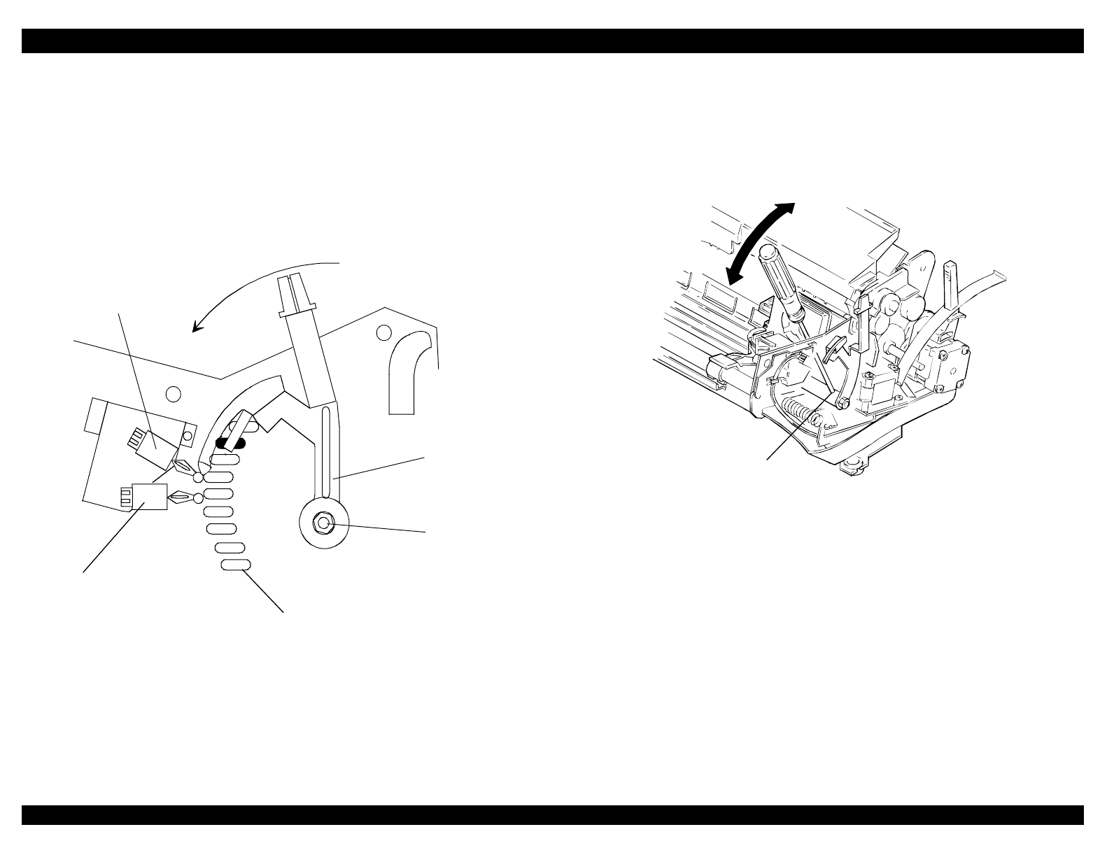
EPSON FX-2180 Service Manual Chapter 5 Adjustments
5-3
3. Attach the print head to the carriage assembly again and tighten the
two CBS screws (3 × 10).
4. Move the print head to the left end column position.
5. Set the paper release lever to the single-sheet position.
6. Loosen the hexagonal nut (M4) securing the PG adjustment lever and
set the PG adjustment lever to the second slot from the rear of the
printer mechanism, as shown in Figure 5-2.
PG SW2
PG adjustment slots
PG adjustment
lever
PG SW1
hexagonal nut
(M4)
Figure 5-2. Setting the PG Adjustment Lever
7. Hold the thickness gauge vertically and insert it between the print head
and platen.
8. Insert a thin screwdriver into the drilled hole located at the right edge of
the rear carriage guide shaft. Then adjust the platen gap by moving the
screwdriver forward or backward until the gap is large enough for a
0.42 mm thickness gauge, but too narrow for a 0.45 mm thickness
gauge.
drilled hole
Figure 5-3. Adjusting the Platen Gap
9. When the gap is correct at the left end column, check the platen gap at
the center and right end column positions.
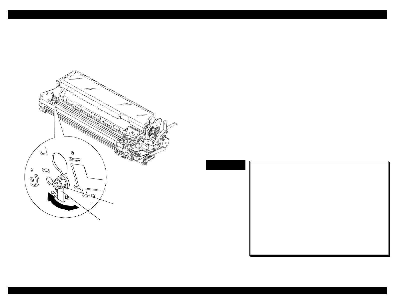
EPSON FX-2180 Service Manual Chapter 5 Adjustments
5-4
10. If the platen gap is wider at the left end column than at the right end
column, adjust the parallelism for the rear carriage guide shaft by
moving the parallelism adjustment bushing backward. If the platen gap
is narrower at the left end column than at the right end column, move
the parallelism adjustment bushing forward. See Figure 5-4.
parallelism adjustment bushing
hexagonal nut
Figure 5-4. Adjusting the Parallelism of the Carriage Guide Shaft
11. Continue performing steps 7 through 10 until the platen gap is correct
at all three positions (left end, right end, and center). After completing
the adjustment, remove the screwdriver from the drilled hole in the rear
carriage guide shaft.
12. Remove the print head from the carriage assembly.
13. Insert the ribbon mask into the ribbon mask holder. Then attach the
print head to the carriage assembly, and tighten the two CBS screws (3
× 8) to secure the print head.
14. Tighten the hexagonal nut (M4) to secure the PG adjustment lever.
5.2.2 Bidirectional Print Alignment (Bi-d) Adjustment
This section describes how to adjust the bidirectional print alignment. This
adjustment is required after you remove or replace the printer mechanism.
It is also necessary after you replace the main board assembly or the
EEPROM, because the adjustment values are written to the EEPROM on
the main board.
You can perform this adjustment using the Settings diskette, the control
panel buttons and lights, or the Remote utility. This section first describes
how to perform the bi-d adjustment using the Settings diskette, and then
describes how to perform the adjustment from the control panel.
IMPORTANT
9
When you replace the main board, reset the
factory settings as described in section 5.2.3
first, and then adjust the bidirectional print
alignment.
Do not adjust the bidirectional print alignment if
the input voltage is fluctuating significantly.
Before you run GWBASIC, exit Windows and go
to the DOS prompt.
When you adjust the bidirectional print
alignment, use continuous paper that is
15 inches (381 mm) wide.
Clearing the EEPROM does not reset the
bidirectional adjustment values.
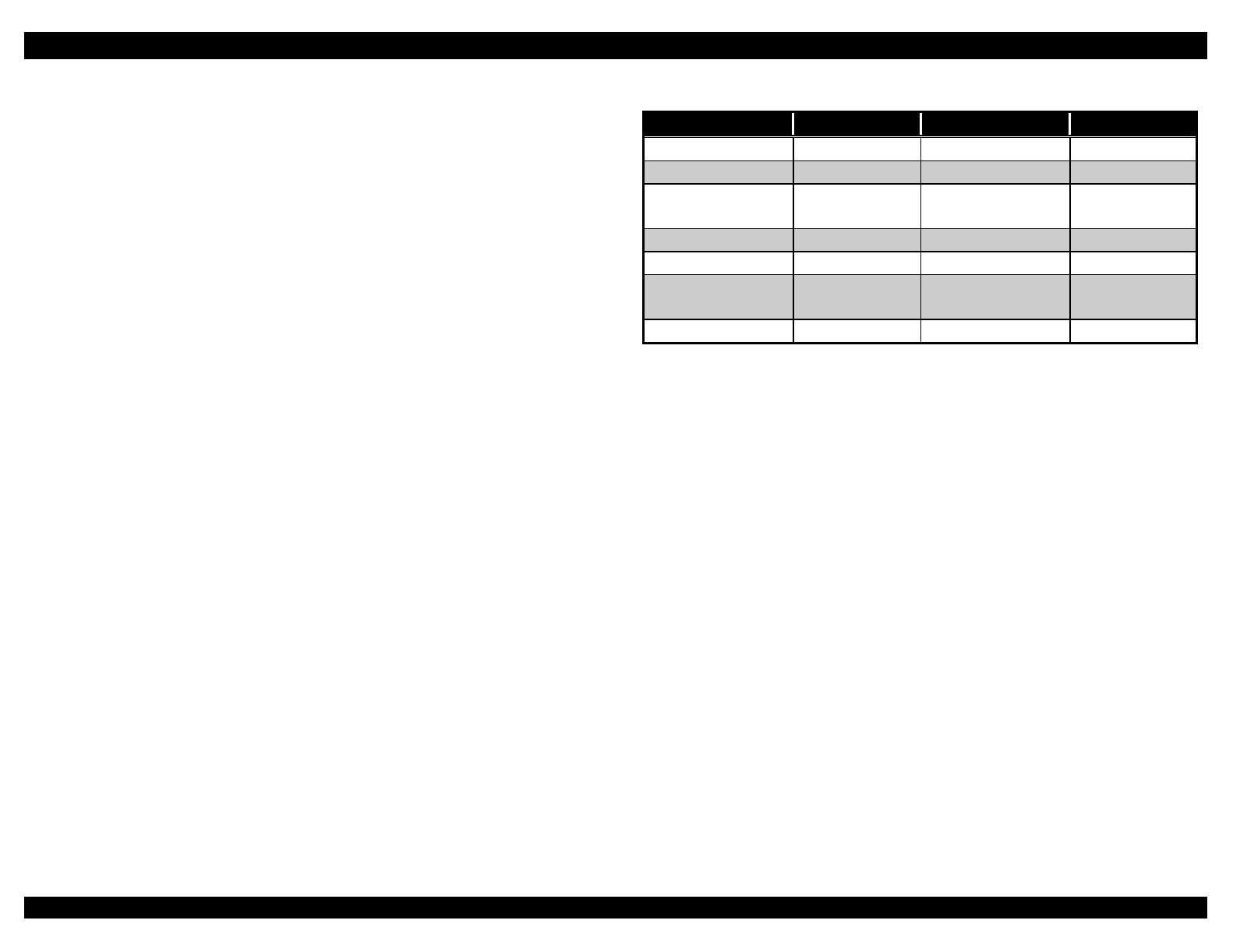
EPSON FX-2180 Service Manual Chapter 5 Adjustments
5-5
5.2.2.1 Performing the Bi-d Adjustment Using the Settings
Diskette
1. Make sure the PC is turned off. Insert the Settings diskette into drive A
of the PC and turn on the PC.
2. Exit Windows and go to the DOS prompt.
3. At the DOS prompt, type GWBASIC J10a72v.bas and press Enter.
You see the Printer Select menu.
Program : J****** Setting : *****
9 pins VR 0 = 0 VR 1 = 0 VR 2 = 0
[ Printer select ]
> (1) 9 pins
(2) 24 pins
Figure 5-5. Printer Select Menu
4. Use the ↑ or ↓ key to highlight 9 pins and then press Enter. You see
the Setting File menu.
Program : J****** Setting : ******
9 pins VR 0 = 0 VR 1 = 0 VR 2 = 0
[ Setting File ]
> (1) DEFSTD
(2) EURSTD
(3) NLSP
(4) ITALIC
(5) RUSSIAN
Figure 5-6. Setting File Menu
5. Use the ↑ or ↓ key to highlight the factory setting for the printer’s
destination and press Enter. Refer to Table 5-3 for destination settings.
Table 5-3. Destination Settings
Destination Setting Destination Setting
EAI USASTD EAI (Latin) USASTD
EIRO EURSTD EDG EURSTD
EUL EURSTD EUL
(SCANDINAVIA)
EURSTD
EFS EURSTD EIS EURSTD
EIB EURSTD EDG (NLSP) NLSP
EUL (MIDDLE
EAST)
DEFSTD EAL DEFSTD
ESP DEFSTD EHK DEFSTD
After you select the destination setting, you see the Main menu.
Program : J****** Setting : *****
9 pins VR 0 = 0 VR 1 = 0 VR 2 = 0
[ Main MENU ]
> (1) Bi-d Adjust (6) Envelope
(2) FF paper (7) ---- N/A ----
(3) A3 Cut sheet (8) -- SUB MENU
(4) A4 1P Cut sheet
(5) A4 6P Cut sheet
Figure 5-7. Main Menu
6. Use the ↑ or ↓ key to highlight Bi-d Adjust and press Enter.
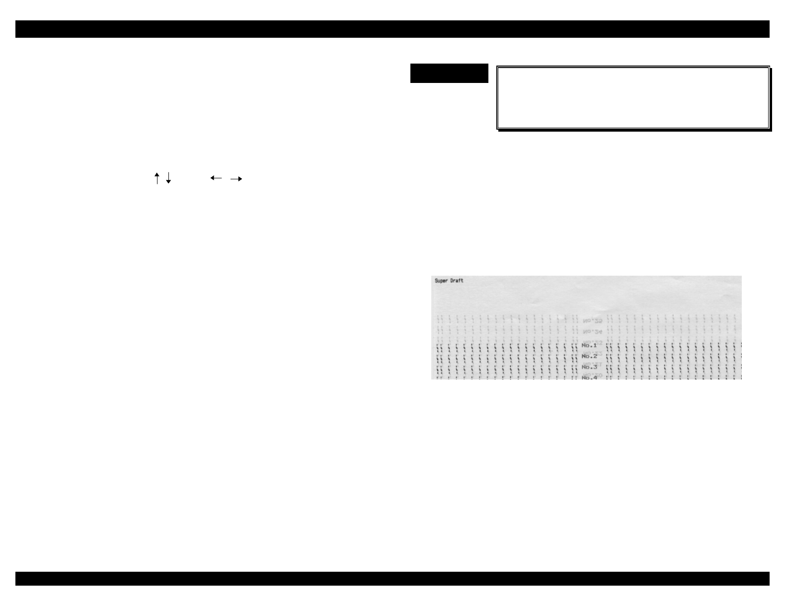
EPSON FX-2180 Service Manual Chapter 5 Adjustments
5-6
You see the Bi-d Adjustment menu.
< Bi-d adjustment >
> Mode 0 = 0
Mode 1 = 0
Mode 2 = 0
Cancel Print Speed Value Write Default
[ ESC ] [ SPACE ] [ ] [ ] [ RET ] [ HOME ]
Figure 5-8. Bi-d Adjustment Menu
7. Use the ↑ or ↓ key to highlight the mode. Then press the space bar to
print the current bi-d print alignment pattern for that mode.
Mode 0 VR0 = 0
HHHHHHHHHHHHHHHHHHHHHHHHHHHHHHHHHHHHHHHHHHHHHHHHHHHHH
HHHHHHHHHHHHHHHHHHHHHHHHHHHHHHHHHHHHHHHHHHHHHHHHHHHHH
HHHHHHHHHHHHHHHHHHHHHHHHHHHHHHHHHHHHHHHHHHHHHHHHHHHHH
HHHHHHHHHHHHHHHHHHHHHHHHHHHHHHHHHHHHHHHHHHHHHHHHHHHHH
Figure 5-9. Current Bi-d Print Alignment Pattern
8. If the bi-d pattern is not aligned properly, you need to adjust it by
changing the input value with the ← or → key. If the second row is
shifted to the right of the first row, change the value by pressing the
← key. If the second row is shifted to the left of the first row, change
the value by pressing the → key. Press the space bar to print the new
bi-d pattern.
9. Perform steps 7 and 8 for each mode (0,1, and 2).
10. After you correct the bidirectional print alignment for each print mode,
press Enter to print the adjustment values. The program returns to the
Main menu.
11. To exit the program, press Esc until you return to the DOS prompt.
IMPORTANT
9
The adjustment values are stored in the EEPROM
only when you turn off the printer. Turn the printer
off and then on again after you perform the bi-d
adjustment.
5.2.2.2 Performing the Bi-d Adjustment from the Control
Panel
1. Make sure that continuous paper is loaded and the printer is turned off.
2. Turn on the printer while holding down the Pause button to enter
bidirectional print alignment adjustment mode. The printer prints an
instruction sheet that contains 25 Super Draft mode alignment
patterns.
Figure 5-10. Super Draft Alignment Patterns
3. Look for the pattern with the best alignment on the sheet.
EPSON FX-2180 Service Manual Chapter 5 Adjustments
5-7
4. Press the LF/FF or Load/Eject button until the Pitch lights indicate the
number of the pattern with the best alignment, as shown in
Figure 5-11.
1o o o 14 n n n
2o o n 15 n n f
3o o f 16 n f o
4o n o 17 n f n
5o n n 18 n f f
6o n f 19 f o o
7o f o 20 f o n
8o f n 21 f o f
9n f f 22 f n o
10 n o o 23 f n n
11 n o n 24 f n f
12 n o f 25 f f o
13 n o o
Figure 5-11. Pitch Lights
5. Press the Font button to save your selection. The printer then prints 25
Draft mode alignment patterns.
6. Repeat steps 3 through 5 for the Draft and NLQ modes.
7. After you perform the NLQ mode bi-d adjustment, turn off the printer to
save the bi-d values you selected in the EEPROM on the main board.
Turning off the printer also exits the bidirectional adjustment mode.
5.2.3 Factory Settings
This section describes how to reset the factory settings. You must reset
the factory settings after you replace the main board or the EEPROM. You
can perform this procedure only with the Settings diskette.
IMPORTANT
9
After you select the factory settings in the Setting
File menu, be sure to run the Check program from
the Main menu. Running the Check program
writes the selected factory settings to the
EEPROM and prints several check patterns.
1. Make sure the PC is turned off. Insert the Settings diskette into drive A
of the PC and turn on the PC.
2. Exit Windows and go to the DOS prompt.
3. At the DOS prompt, type GWBASIC J10a72v.bas and press Enter.
You see the Printer Select menu.
Program : J****** Setting : *****
9 pins VR 0 = 0 VR 1 = 0 VR 2 = 0
[ Printer select ]
> (1) 9 pins
(2) 24 pins
Figure 5-12. Printer Select Menu
4. Use the ↑ or ↓ key to highlight 9 pins and then press Enter. You see
the Setting File menu.
Program : J****** Setting : ******
9 pins VR 0 = 0 VR 1 = 0 VR 2 = 0
[ Setting File ]
> (1) DEFSTD
(2) EURSTD
(3) NLSP
(4) ITALIC
(5) RUSSIAN
Figure 5-13. Setting File Menu
5. Use the ↑ or ↓ key to highlight the factory setting for the printer’s
destination and press Enter. Refer to Table 5-3 for destination settings.
After you select the factory setting, you see the Main menu.

EPSON FX-2180 Service Manual Chapter 5 Adjustments
5-8
Program : J****** Setting : *****
9 pins VR 0 = 0 VR 1 = 0 VR 2 = 0
[ Main MENU ]
(1) Bi-d Adjust (6) Envelope
>(2) FF paper (7) ---- N/A ----
(3) A3 Cut sheet (8) -- SUB MENU
(4) A4 1P Cut sheet
(5) A4 6P Cut sheet
Figure 5-14. Main Menu
6. Select one of the Check programs (selections 2 through 6) depending
on the paper loaded in the printer. Run the Check program to write the
selected factory settings to the EEPROM and print several check
patterns.
7. To exit the program, press Esc until you return to the DOS prompt.
5.2.4 TPE Level Reset
This section describes how to reset the TPE (top paper end) level (value).
Table 5-1 lists when you need to reset the TPE level. For example, if you
do not perform this adjustment after you replace the PW sensor assembly,
the printer does not recognize that the PW sensor has been replaced, and
the ability of the new sensor to operate properly is limited. You can perform
this procedure using the Settings diskette only.
IMPORTANT
9
After you perform the TPE level reset adjustment,
the printer automatically prints the reset value for
the TPE level. Check that the reset value is FF.
1. Make sure the PC is turned off. Insert the Settings diskette into drive A
of the PC and turn on the PC.
2. Exit Windows and go to the DOS prompt.
3. At the DOS prompt, type GWBASIC J10a72v.bas and press Enter.
You see the Printer Select menu.
Program : J****** Setting : *****
9 pins VR 0 = 0 VR 1 = 0 VR 2 = 0
[ Printer select ]
> (1) 9 pins
(2) 24 pins
Figure 5-15. Printer Select Menu
4. Use the ↑ or ↓ key to highlight 9 pins and then press Enter. You see
the Setting File menu.
Program : J****** Setting : ******
9 pins VR 0 = 0 VR 1 = 0 VR 2 = 0
[ Setting File ]
> (1) DEFSTD
(2) EURSTD
(3) NLSP
(4) ITALIC
(5) RUSSIAN
Figure 5-16. Setting File Menu
5. Use the ↑ or ↓ key to highlight the factory setting for the printer’s
destination and press Enter. Refer to Table 5-3 for destination settings.
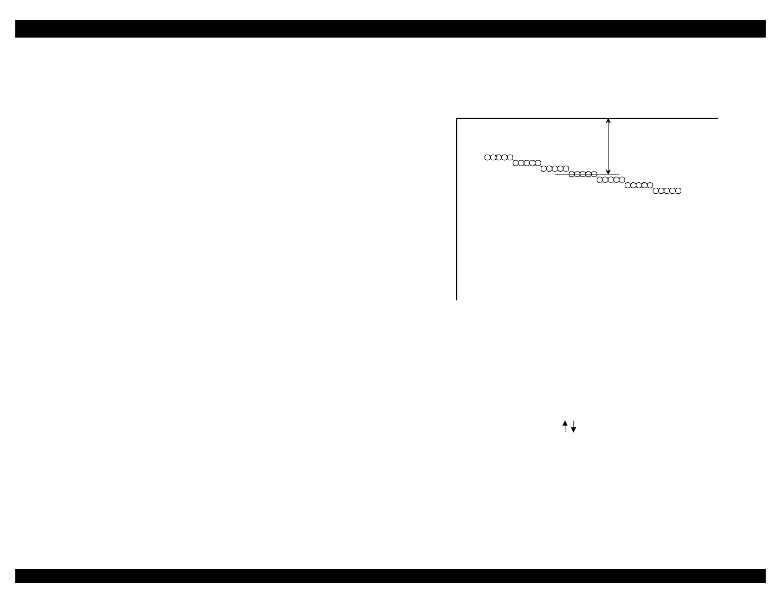
EPSON FX-2180 Service Manual Chapter 5 Adjustments
5-9
After you select the factory setting, you see the Main menu.
Program : J****** Setting : *****
9 pins VR 0 = 0 VR 1 = 0 VR 2 = 0
[ Main MENU ]
(1) Bi-d Adjust (6) Envelope
(2) FF paper (7) ---- N/A ----
(3) A3 Cut sheet > (8) -- SUB MENU
(4) A4 1P Cut sheet
(5) A4 6P Cut sheet
Figure 5-17. Main Menu
6. Use the ↑ or ↓ key to highlight SUB MENU and press Enter. You see
the following submenu:
Program : J****** Setting : *****
9 pins VR 0 = 0 VR 1 = 0 VR 2 = 0
[ Sub MENU ]
(1) Memory SW Print (6) EEPROM Print
(2) EEPROM Reset (7) -- EXIT
>(3) TPE Adjust
(4) Pitch 1P
(5) Pitch 20P
Figure 5-18. Submenu
7. Use the ↑ or ↓ key to highlight TPE Adjust and press Enter.
8. Insert an A4-size sheet of paper into the printer’s rear paper guide.
Make sure the paper is positioned in the portrait orientation. The TPE
check pattern and the current TPE position value is printed, as shown
in Figure 5-19.
9. Measure the distance from the top of the paper to the 0 level line, as
shown below. Check whether the distance equals 0.335 inches
± 0.020 inches (8.5 mm ± 0.5 mm).
-9 -6 -3 0 3 6 9
TOF
TPE position = 00,
Figure 5-19. TOF Measurement
After the page is printed, you see the following menu:
< TPE adjustment >
TPE Pos. = 0
Exit Print Value Write Default
[ESC] [SPACE] [ (0-9)] [RET] [HOME]
Figure 5-20. TPE Adjustment Menu
10. If your TOF measurement is not equal to 0.335 inches ± 0.020 inches
(8.5 mm ± 0.5 mm), use the ↑ or ↓ key to change the TOF value. Then
press Enter.

EPSON FX-2180 Service Manual Chapter 5 Adjustments
5-10
11. To exit the program, press Esc until you return to the DOS prompt.
IMPORTANT
9
The adjusted TPE value is stored in the EEPROM
only when you turn off the printer. Turn the printer
off and then on again after you perform the TPE
level reset adjustment.

MAINTENANCE
&+$37(5
EPSON FX-2180 Service Manual Chapter 6 Maintenance
6-1
6.1 Preventive Maintenance
To keep the printer operating properly, regularly clean the exterior case
using denatured alcohol and also vacuum the inside of the printer to
remove any dust and paper debris.
After you clean the printer, check that it is adequately lubricated as
described in the next section. Before returning the printer to the customer,
inspect the springs and paper feed rollers, and check the basic operation of
the printer.
WARNING
Disconnect the printer from the external AC power
source before you perform any maintenance
procedures.
CAUTION
Do not use thinner, trichloroethylene, or ketone-
based solvents on the plastic components of the
printer.
6.2 Lubrication
Table 6-1 provides information about the recommended lubricants. These
lubricants are EPSON G-26 and O-2, which have been tested extensively
and found to comply with the needs of the printer.
EPSON recommends the printer be lubricated at the points illustrated in
Figures 6-1 and 6-2. Table 6-2 lists each lubrication point along with the
lubricant and amount recommended for that point.
Before applying a lubricant, be sure the surface to be lubricated is clean.
Do not apply too much lubricant, because this may damage nearby printer
parts.
Table 6-1. Lubricants
Type Name Quantity Availability Part Number
Grease G-26 40 g EPSON B702600001
Oil O-2 40 cc EPSON B710200001

EPSON FX-2180 Service Manual Chapter 6 Maintenance
6-2
Table 6-2. Lubrication Points
Ref. No. Lubrication Points Quantity Lubricant
1 Cam surfaces of the 34.5 mm
spur gears
2 mm width,
halfway
G-26
2The platen gap adjustment
slots on the right frame
2 mm width,
from the top
slot to the 3rd
slot from the
bottom
G-26
3 The end of the shaft of the
drive roller assembly and the
cutout section on the left frame
About ½ the
size of a grain
of rice
G-26
4Oil pads Half of the pads O-2
5 RD planetary shaft and
planetary lever leaf spring
About ½ the
size of a grain
of rice
G-26
6RD housing
• Side of shafts: 3 points
• Inside hole: 1 point
About ½ the
size of a grain
of rice
G-26
7 5 points on the RD assembly
gear teeth
About ½ the
size of a grain
of rice
G-26
8The side of the RD ratchet
shaft
About the size
of a grain of
rice
G-26
9 10 contact points between the
paper guide and the release
shaft
About the size
of a grain of
rice
G-26
Note: Apply lubricants when you are reassembling the printer. For
lubrication points, see the following figures.
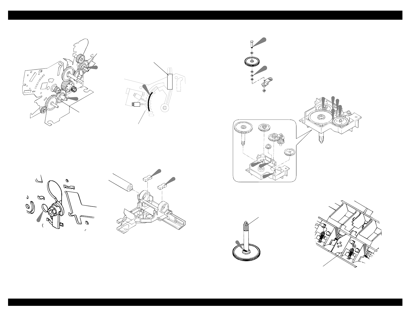
EPSON FX-2180 Service Manual Chapter 6 Maintenance
6-3
34.5 mm spur gear
34.5 mm spur gear
1
1
platen gap adjustment slots
platen gap adjustment lever
2
4
4
3
Figure 6-1. Lubrication Points (1 of 2)
6
6
777
7
7
6
5
5
9
9
rear frame
RD ratchet
8
Figure 6-2. Lubrication Points (2 of 2)

APPENDIX
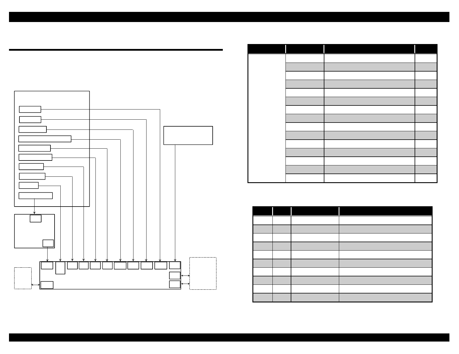
EPSON FX-2180 Service Manual Appendix
A-1
A.1 Connector Summary
The figure below shows how the primary components of the printer are
connected. Table A-1 summarizes the functions and sizes of the
connectors.
printer mechanism
PG sensor
release lever position sensor
rear PE sensor
front PE sensor
HP sensor
PW sensor
print head
C244 MAIN board assembly
CN13
CN5
CN6
CN4
cover open sensor
C166 PSB/PSE
C244 PSH board assembly
CN3CN12
CN7
CN8
CN9
PF motor
CR motor
CN11 CN10CN15
CN2
CN1
PNL board assembly
CN14
CSF
bin 1 CN1
host
computer
parallel I/F
CN2 optional I/F
Figure A-1. Cable Connections
Table A-1. Connector Summary
Board Connector Function Pins
CN1 Parallel interface 36
CN2 Type B interface 36
CN3 Power supply board 10
CN4 HP sensor 3
CN5 Rear PE sensor 3
CN6 Front PE sensor 2
CN7 PW sensor 4
CN8 Print head 18
CN9 Print head 16
CN10 PF motor 4
CN11 CR motor 5
CN12 Release lever position sensor 4
CN13 PG sensor 4
CN14 CSF bin 1 10
Main
Board
Assembly
CN15 PNL board 22
Table A-2. Connector Pin Assignments − CN3
Pin I/O Signal Name Function
1GP
2GP
3 I +35V +35 VDC line
4 I +35V +35 VDC line
5GND Signal ground
6GND Signal ground
7 I +5V +5 VDC line
8 I +5V +5 VDC line
9 I PWDN Power down detection signal
10 O PSC Power switch on/off signal
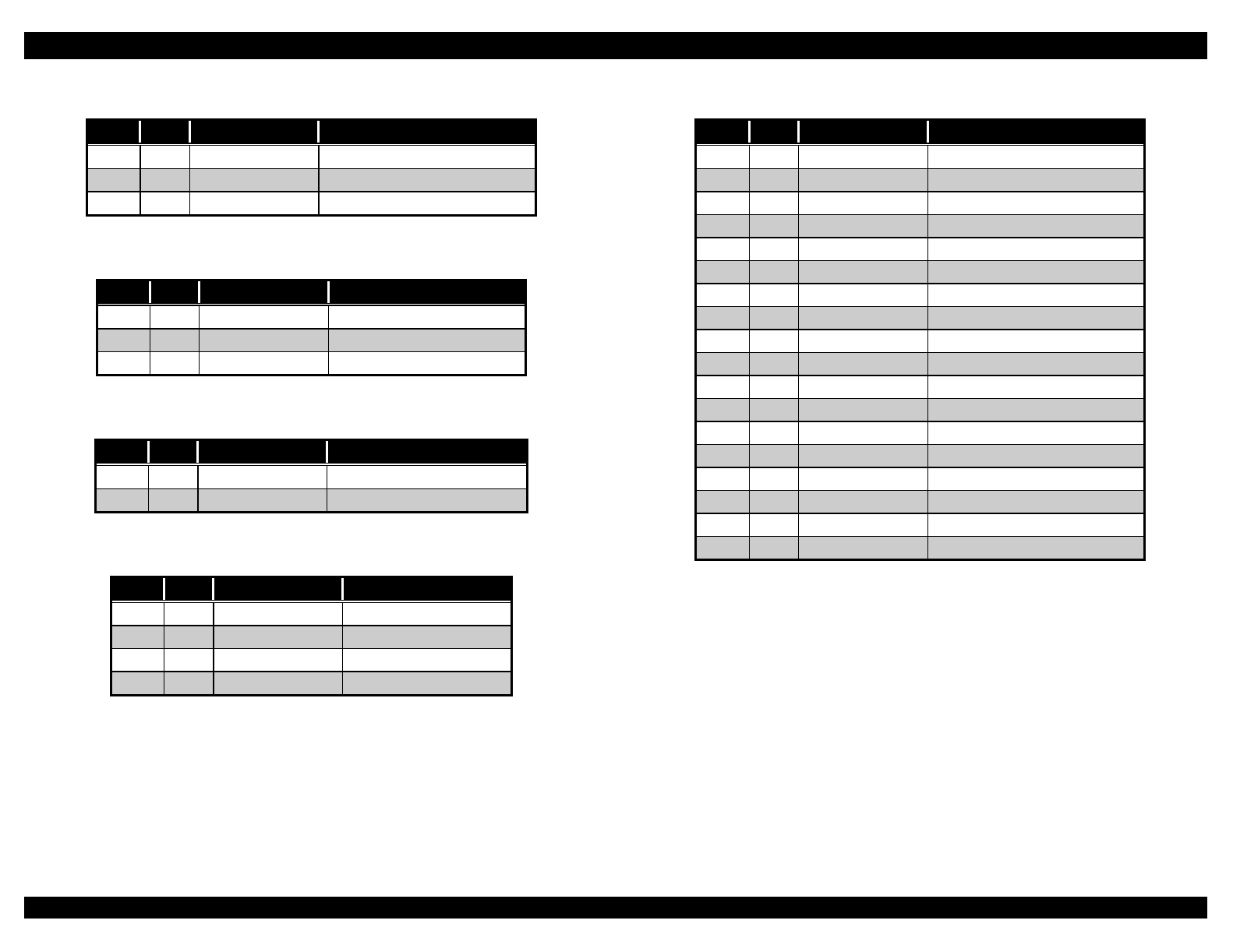
EPSON FX-2180 Service Manual Appendix
A-2
Table A-3. Connector Pin Assignments − CN4
Pin I/O Signal Name Function
1 I HP CR home position signal
2GND Signal ground
3+5V +5 VDC
Table A-4. Connector Pin Assignments − CN5
Pin I/O Signal Name Function
1+5V +5 VDC
2 I PE Rear paper end signal
3GND Signal ground
Table A-5. Connector Pin Assignments − CN6
Pin I/O Signal Name Function
1PE Front paper end signal
2 I GND Signal ground
Table A-6. Connector Pin Assignments − CN7
Pin I/O Signal Name Function
1 I E PW sensor signal
2GND Signal ground
3+5V +5 VDC line
4A +5 VDC line
Table A-7. Connector Pin Assignments − CN8
Pin I/O Signal Name Function
1NC Not connected
2 O HD1 Head data 1
3 O HD9 Head data 9
4 O HD13 Head data 13
5 O HD7 Head data 7
6+35V +35 VDC line
7NC Not connected
8 O HD18 Head data 18
9+35V +35 VDC line
10 O HD12 Head data 12
11 +35V +35 VDC line
12 +35V +35 VDC line
13 NC Not connected
14 O HD6 Head data 6
15 O HD10 Head data 10
16 I HTMP Head temperature signal
17 +5V +5 VDC line
18 NC Not connected
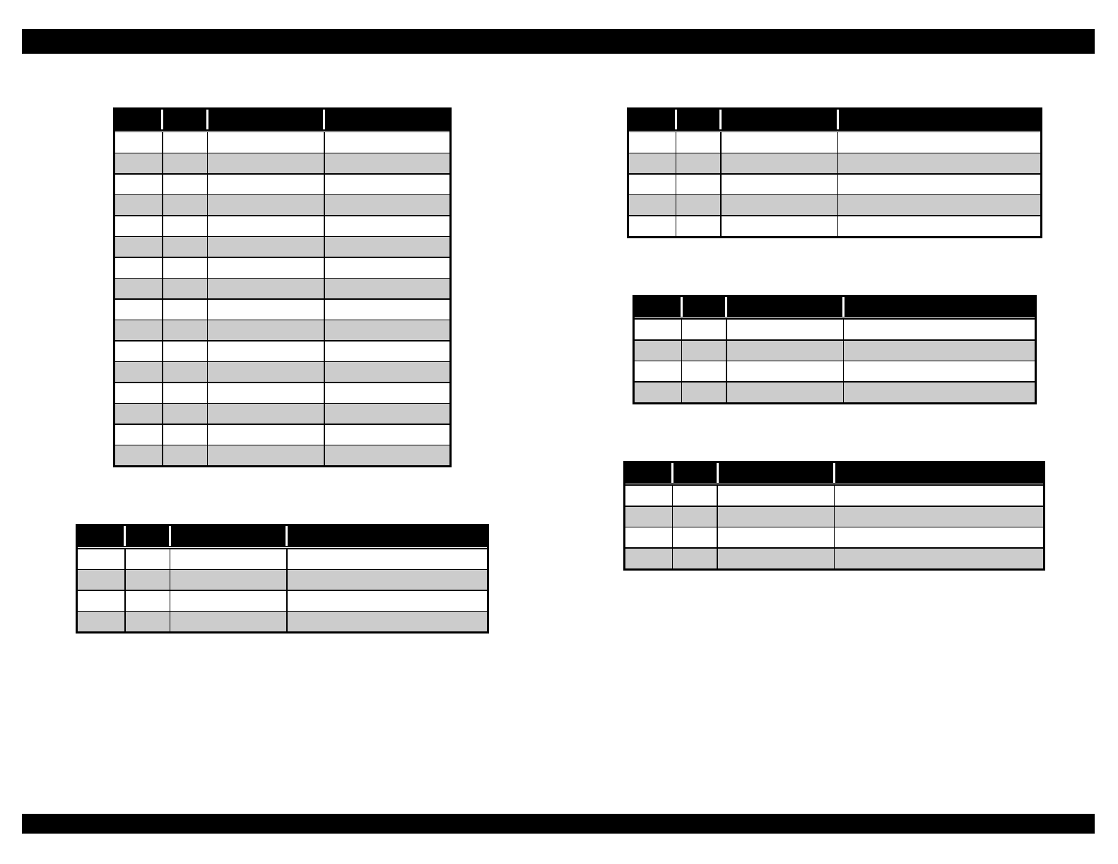
EPSON FX-2180 Service Manual Appendix
A-3
Table A-8. Connector Pin Assignments − CN9
Pin I/O Signal Name Function
1 O HD3 Head data 3
2NC Not connected
3 O HD15 Head data 15
4+35V +35 VDC line
5 O HD2 Head data 2
6+35V +35 VDC line
7 O HD5 Head data 5
8 O HD16 Head data 16
9 O HD11 Head data 11
10 +35V +35 VDC line
11 O HD17 Head data 17
12 +35V +35 VDC line
13 NC Not connected
14 O HD14 Head data 14
15 O HD4 Head data 4
16 O HD8 Head data 8
Table A-9. Connector Pin Assignments − CN10
Pin I/O Signal Name Function
1 O PF A PF motor phase A signal
2 O PF B PF motor phase B signal
3 O PF −A PF motor phase /A signal
4 O PF −B PF motor phase /B signal
Table A-10. Connector Pin Assignments − CN11
Pin I/O Signal Name Function
1 O CR A CR motor phase A signal
2 O CR −ACR motor phase /A signal
3 O CR B CR motor phase B signal
4 O CR −BCR motor phase /B signal
5CR COM CR motor common
Table A-11. Connector Pin Assignments − CN12
Pin I/O Signal Name Function
1 I RELEASE1 Release sensor 1 signal
2GND Signal ground
3 I RELEASE2 Release sensor 2 signal
4GND Signal ground
Table A-12. Connector Pin Assignments − CN13
Pin I/O Signal Name Function
1 I PG1 Platen gap sensor 1 signal
2GND Signal ground
3 I PG2 Platen gap sensor 2 signal
4GND Signal ground
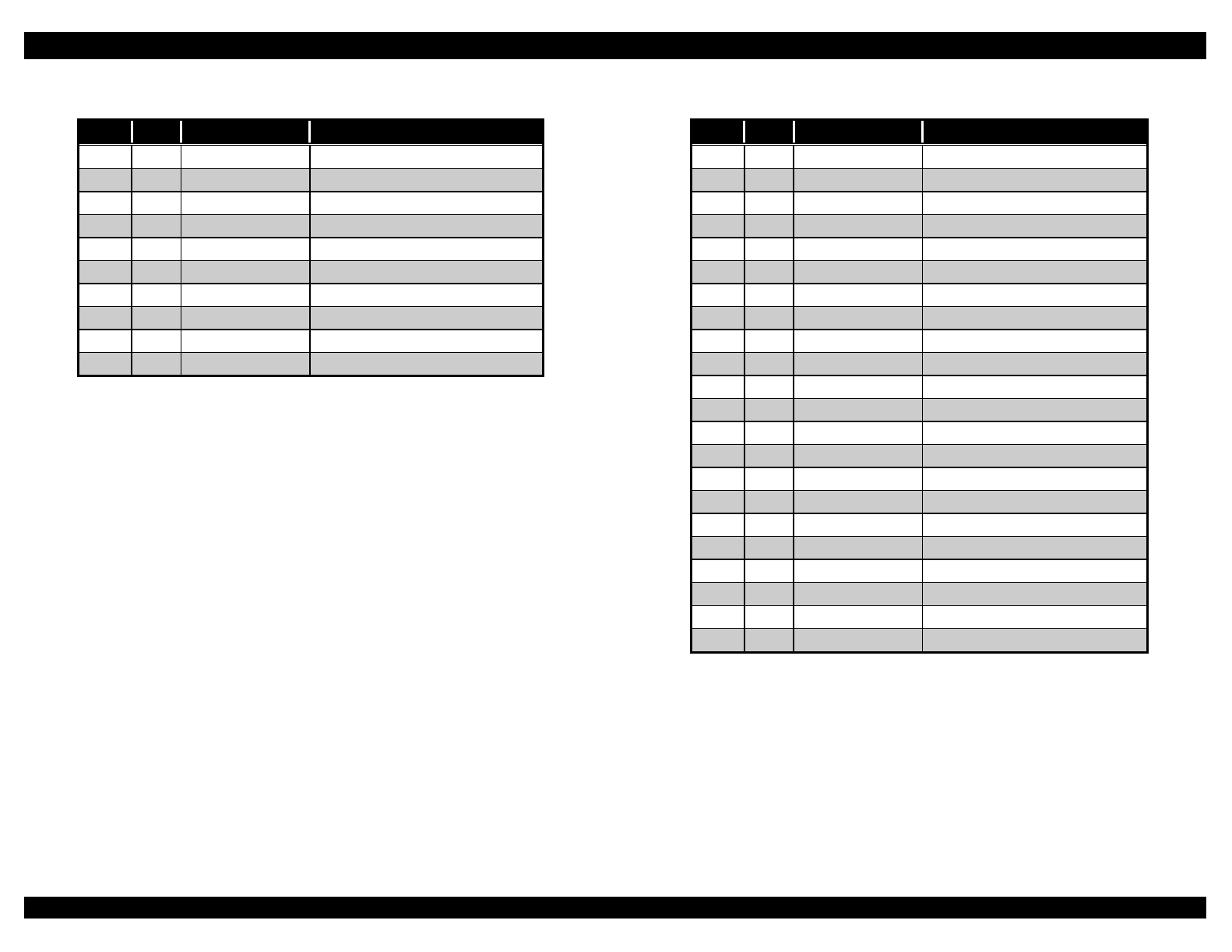
EPSON FX-2180 Service Manual Appendix
A-4
Table A-13. Connector Pin Assignments − CN14
Pin I/O Signal Name Function
1 O A CSF motor phase A signal
2 O B CSF motor phase B signal
3O −A CSF motor phase /A signal
4 O −BCSF motor phase /B signal
5 O HOLD CSF motor hold signal
6+5V +5 VDC line
7GND Signal ground
8GND Signal ground
9+35V +35 VDC line
10 +35V +35 VDC line
Table A-14. Connector Pin Assignments − CN15
Pin I/O Signal Name Function
1 I COPEN Cover open sensor signal
2 O PAUSE Pause LED signal
3+5V +5 VDC line
4 O POUTL Paper out LED signal
5 O RESRVL Pitch select LED signal
6 I PAUSSW Pause button signal
7 O TBIN2L Tear off/bin select signal
8 O TBIN1L Tear off/bin select signal
9 O PITC1L Pitch select LED
10 O PITC2L Pitch select LED
11 FONT3L Not connected
12 O FONT2L FONT LED signal
13 O FONT1L FONT LED signal
14 GND Signal ground
15 GND Signal ground
16 I FONTSW Font button signal
17 I PITCSW Pitch button signal
18 I TBINSW Tear off/bin button signal
19 I PSC Operate button signal
20 I LDEJSW Load/Eject button signal
21 I LFFFSW LF/FF button signal
22 FG Frame ground
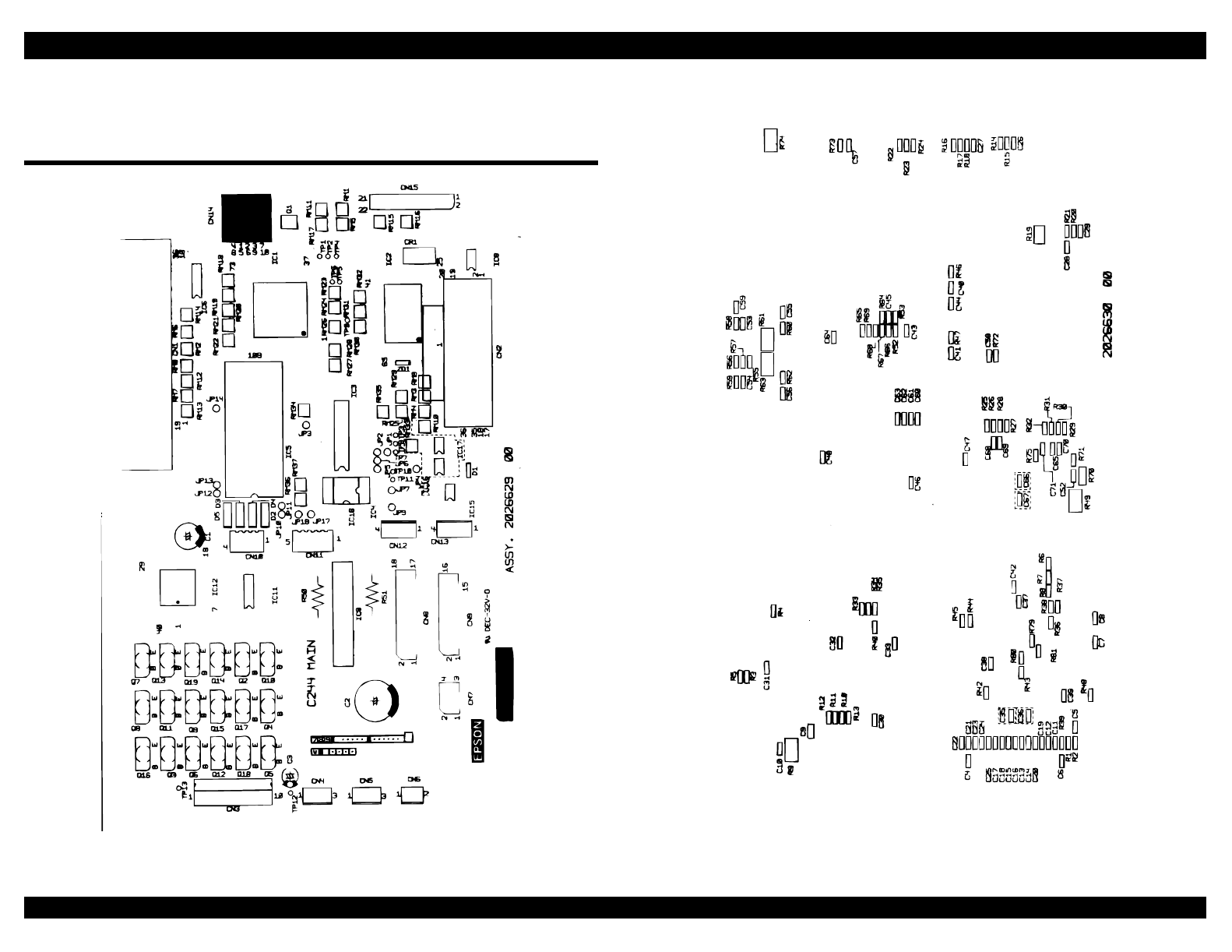
EPSON FX-2180 Service Manual Appendix
A-5
A.2 Circuit Board Component Layout
Diagrams
Figure A-2. C244 MAIN Board Component Layout Diagram (1 of 2)
Figure A-3. C244 MAIN Board Component Layout Diagram (2 of 2)
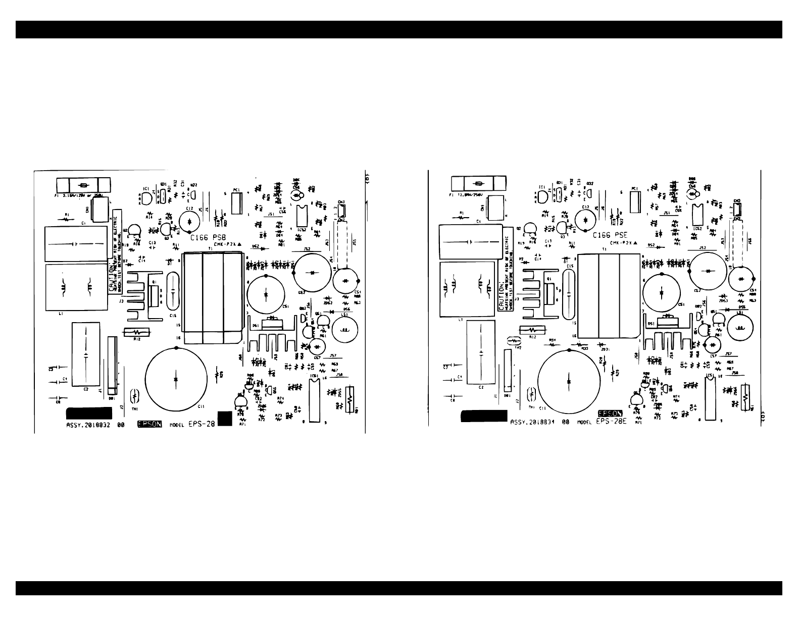
EPSON FX-2180 Service Manual Appendix
A-6
Figure A-4. C166 PSB Board Component Layout Diagram Figure A-5. C166 PSE Board Component Layout Diagram

EPSON FX-2180 Service Manual Appendix
A-7
A.3 Circuit Board and Exploded Diagrams
This section provides the following diagrams:
C244 MAIN circuit board diagram
C166 PSB circuit board diagram
C166 PSE circuit board diagram
C244 PSH circuit board diagram
FX-2180 exploded diagram (1 of 3)
FX-2180 exploded diagram (2 of 3)
FX-2180 exploded diagram (3 of 3)
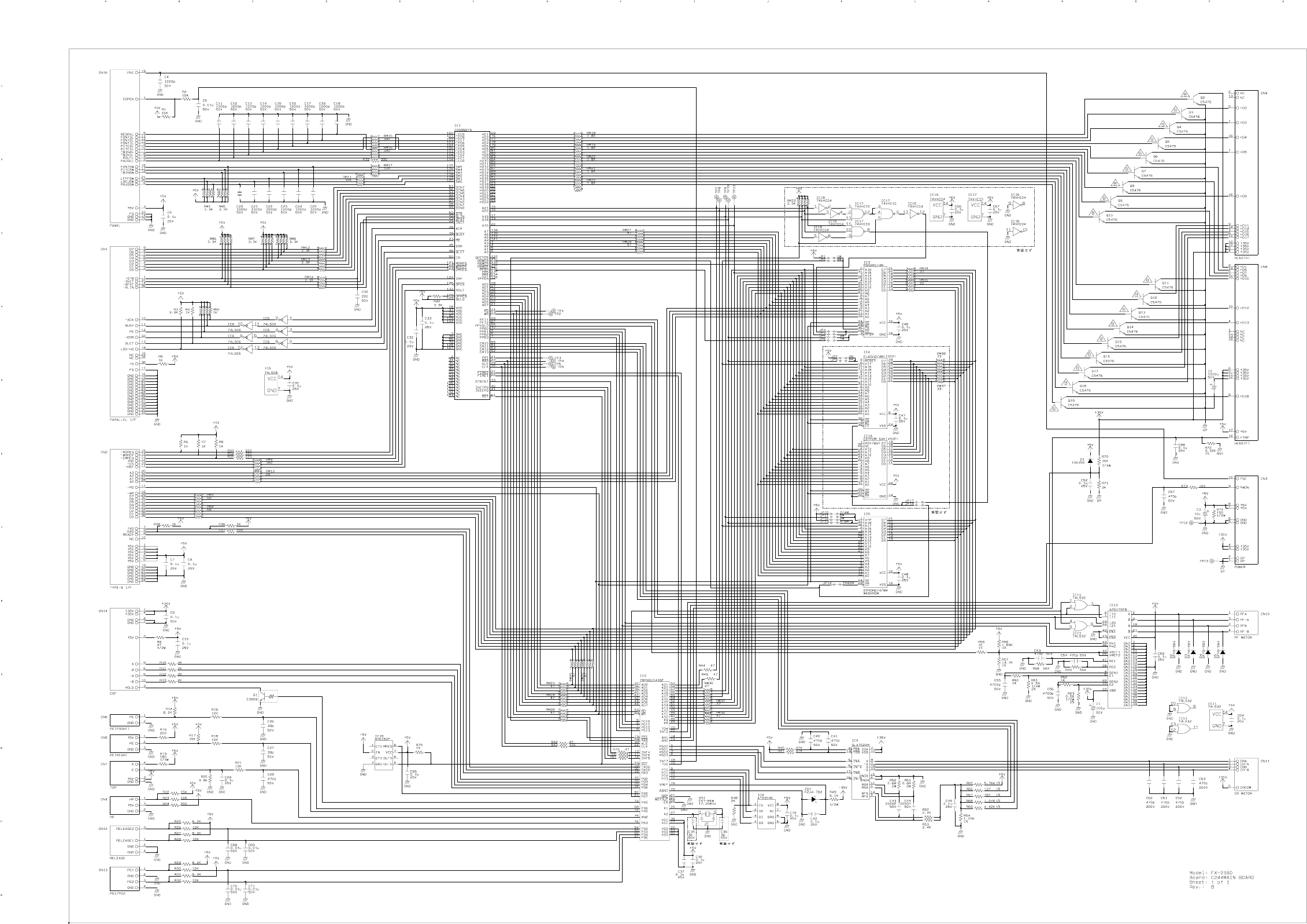
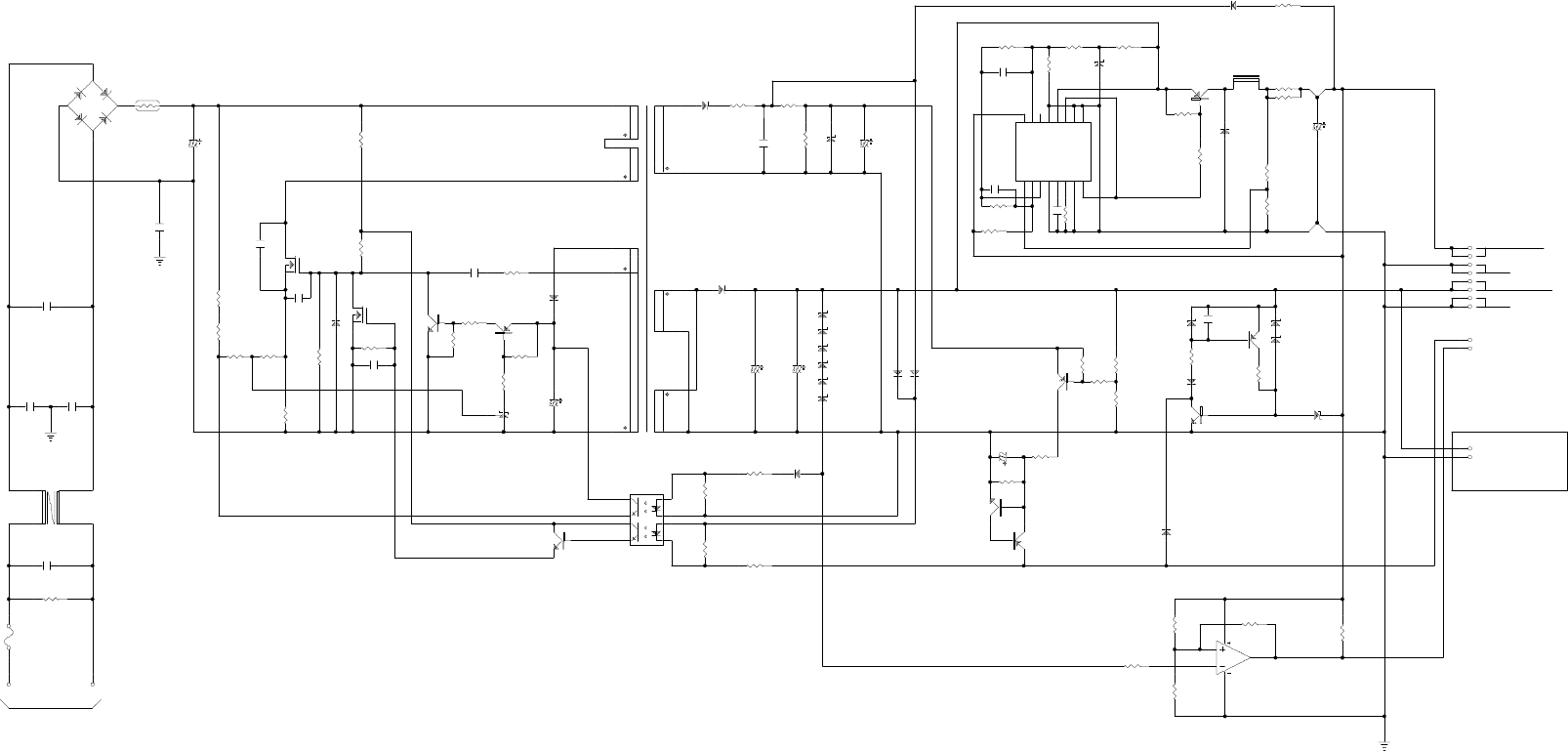
D86
1SS120
R82
2K
1
3
2
4
DB1
D3SBA60
TH1
10ohm/25C
C11
820u/200V R18
150K/0.5W
F
C55
0.1u
D52
ERB43-02
R91
1
14
13
8
7
15
T1
PT-75
R55
20K
ZD54
HZS6A-2 C56
33u/16V
R54
2K
R58
200K
R60
4.7K
ZD55
HZS6A-1L
R59
4.75K 1%
R81
84.5K
1%
R61
300
C59
330p
+
I
1
1
-
I
1
2
F
B
3
D
T
C
4
C
T
5
R
T
6
G
N
D
7
C
1
8
+
I
2
1
6
-
I
2
1
5
R
O
1
4
O
C
1
3
V
C
C
1
2
C
2
1
1
E
2
1
0
E
1
9
IC51
TL494CN
Q51
A1680
R51
470/2W
R88
1
R53
1
L51
HCD-6471HS
R64
2.4K
C54
1000u
D55
ERB83-004
GL
GP
+5V/0.7A
+35V/1.0A
1
2
3
4
5
6
7
8
CN2
RB93-F4-907
ZD52
HZS22-1L
R65
20K
C82
0.01u
R66
200K
C58
0.01u
R63
3.6K
C81
2200p
R67 3K
ZD86
HZS7B-2
ZD51
HZS6A-2
ZD81
HZS6A-2
*
D51 F5KQ100
12
11
10
5
3
F
Q3
A1015
C13
4700p
R31
10K
Q2
C4408
R15
120
D1
ERA83-006
R11
620
*Q1
K2126
C14
2200p
C15
1500p/1.2kV
FQ31
K1725
0.5W
FG
D2
ERA82-004
R29
1.2M
R22
1.2M
C8
2200p
C2
0.1u
FG
C3
4700p
C4
4700p
R20
2.4K
R21
4.7K
R12
0.39/2W
R19
20K
0.5W
35V
R13
4.7K
R14
510
C12
220u
R16
270
R32
20K
C31
2200p
2
1
3
IC1
TL431CLP
R56
150
C51
2200u/50V
9 6
4
C52 ZD82
HZS6A-2
ZD83
HZS6A-2
ZD84
HZS6A-2
ZD85
HZS6A-2
D81
1SS120
D84
1SS120
D85
1SS120
X2
X2
R72
6.2K
R73
1.2K
R71
1.5K
R70
10K
Q53
A1015
C57
470u/6.3V
R74
10K
R75
2.7K
D82
1SS120
R89
1.2K
ZD53
HZS7B-2
ZD87
HZS22-1L
Q55
DTC123ESA
Q81
DTA113ZSA
R90
1.2K
Fan
1
2
CN3
00 8263 0212 00 000
10
CN2
PSC
9
CN2
PWDN
R87
3.6K
R86
270K
Q54
C1815 D83
1SS120
Q82
DTA113ZSA
R83
51K
R57
270
R68
10K R69
1.5K
1
2
3
4
8
7
6
5
PC1
TLP521-2
Q32
DTC124GSA
R1
1M/0.5W
C1
0.22u
F1
3.15A/125V
1
2
3
4
L1
ELF-18D450D
NL
2
B2P3-VH
1
CN1
B2P3-VH
R85
20K
R84
20K
FG
5
6 7
8
4IC52B
NJM2903D
* : Heat sink (Q1,D51)
: CN3 is not mounted. Model : FX-2180
Board : C166PSB BOARD
Sheet : 1 of 1
Rev. : B
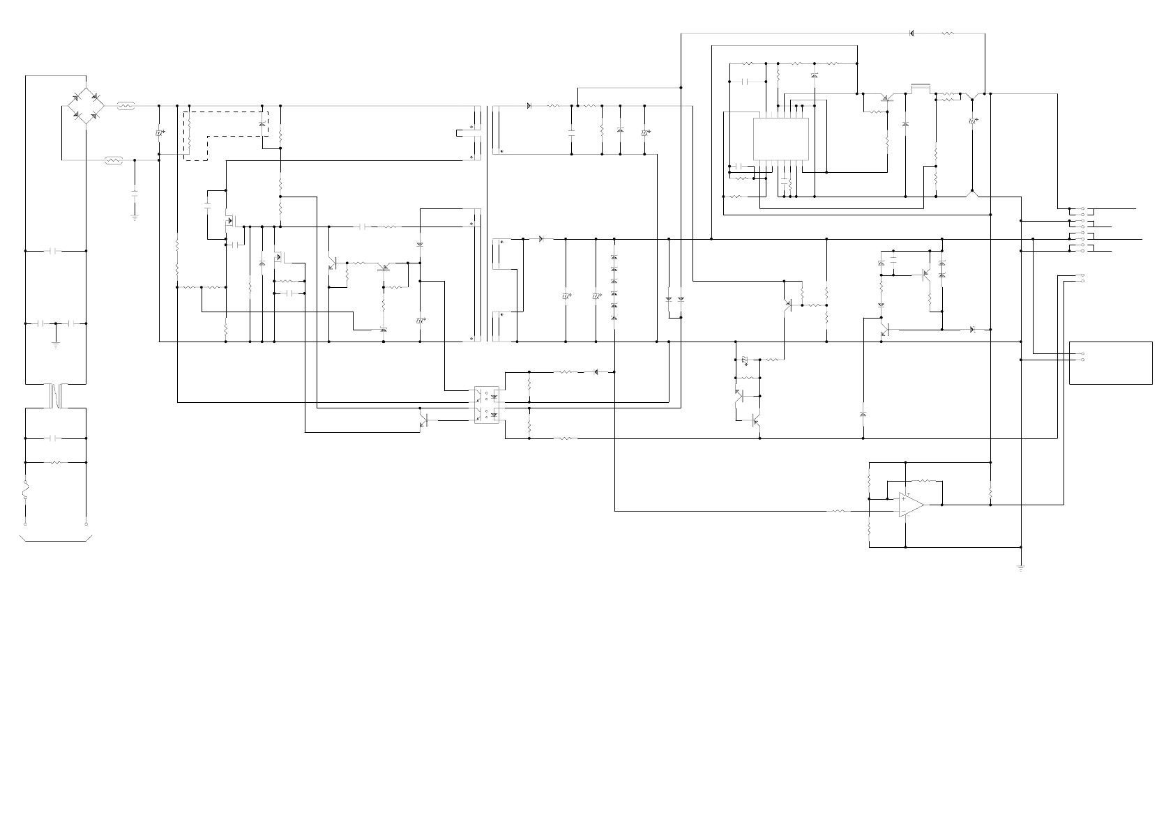
D86
1SS120
R82
2K
1
3
2
4
DB1
D2SBA60
TH1
10ohm /25C
C11
180u/400V
R33
R34
ZD31 R28
150K/0.5W
F
C55
0.1u
D52
E R B43-02
R91
1
14
13
8
7
15
T1
PT-76
R55
20K
ZD54
HZS6A-2 C56
33u/16V
R54
2K
R58
200K
R60
4.7K
ZD55
HZS6A-1L
+I1 1
-I1 2
FB 3
DTC 4
CT 5
RT 6
GND 7
C1 8
+I2
16
-I2
15
RO
14
OC
13
VCC
12
C2
11
E2
10
E1
9
IC 5 1
TL494
R59
4.75K 1%
R81
84.5K
1%
R61
300
C59
330p Q51
A1680
R51
470/2W
R88
1
R53
1
L51
H C D -6471H S
R64
2.4K
C54
1000u
D55
E R B83-004
GL
GP
+5V /0.7A
+ 3 5 V /1 .0 A
1
2
3
4
5
6
7
8
CN2
R B 93-F4-907
ZD52
H ZS 22-1L
R65
20K
C82
0.01u
R66
200K
C58
0.01u
R63
3.6K
C81
2200p
R67 3K
ZD86
HZS7B-2
ZD51
HZS6A-2
ZD81
HZS6A-2
*
D51 F5KQ 100
12
11
10
5
3
F
Q3
A1015
C13
4700p
R31
10K
Q2
C 4408
R15
120
D1
E R A83-006
R18
150K/0.5W
R11
1K
*Q1
K2130
C14
2200p
FQ31
K1725
0.5W
FG
C8
2200p
D2
E R A82-004
R29
1.1M
R22
1.1M
C15
750p/1.5kV
TH2
10ohm /25C
C2
0.1u
FG
C3
2200p
C4
2200p
R20
2.4K
R21
4.7K
R12
0.62/2W
R19
20K
0.5W
35V
R13
4.7K
R14
510
C12
220u
R16
270
R32
20K
C31
2200p
2
1
3
IC 1
TL431C LP
R56
150
C51
9 6
4
ZD82
HZS6A-2
ZD83
HZS6A-2
ZD84
HZS6A-2
ZD85
HZS6A-2
D81
1SS120
C52
2200u/50V X2
D84
D85
1SS120
X2
R72
6.2K
R73
1.2K
R71
1.5K
R70
10K
Q53
A1015
C57
470u/6.3V
R74
10K
R75
2.7K
D82
1SS120
R89
1.2K
ZD53
HZS7B-2
ZD87
H ZS 22-1L
Q55
DTC123ESA
Q81
D TA 113ZS A
R90
1.2K
Fan
1
2
CN3
00 8263 0212 00 000
10
CN2
PSC
9
CN2
PW DN
R87
3.6K
R86
270K
Q54
C 1815 D83
1SS120
Q82
D TA 113ZS A
R83
51K
R57
270
R68
10K R69
1.5K
1
2
3
4
8
7
6
5
PC1
PS 2561L1-2-V
Q32
D TC 124G SA
R1
1 M /0 .5 W
F1
T2.0AH /250V
C1
0.47u
1
2
3
4
L1
S S24H -08150
NL
2
B2P3-VH
1
CN1
B2P3-VH
R85
20K
R84
20K
FG
5
6 7
8
4IC 52B
N JM 2903D
* : H eat sink (Q 1, D 51)
: C N 3,ZD 31,R 33 and R 34 are not m ounted.
M odel : FX -2180
Board : C166PSE BO ARD
S h e e t : 1 o f 1
R e v . : B
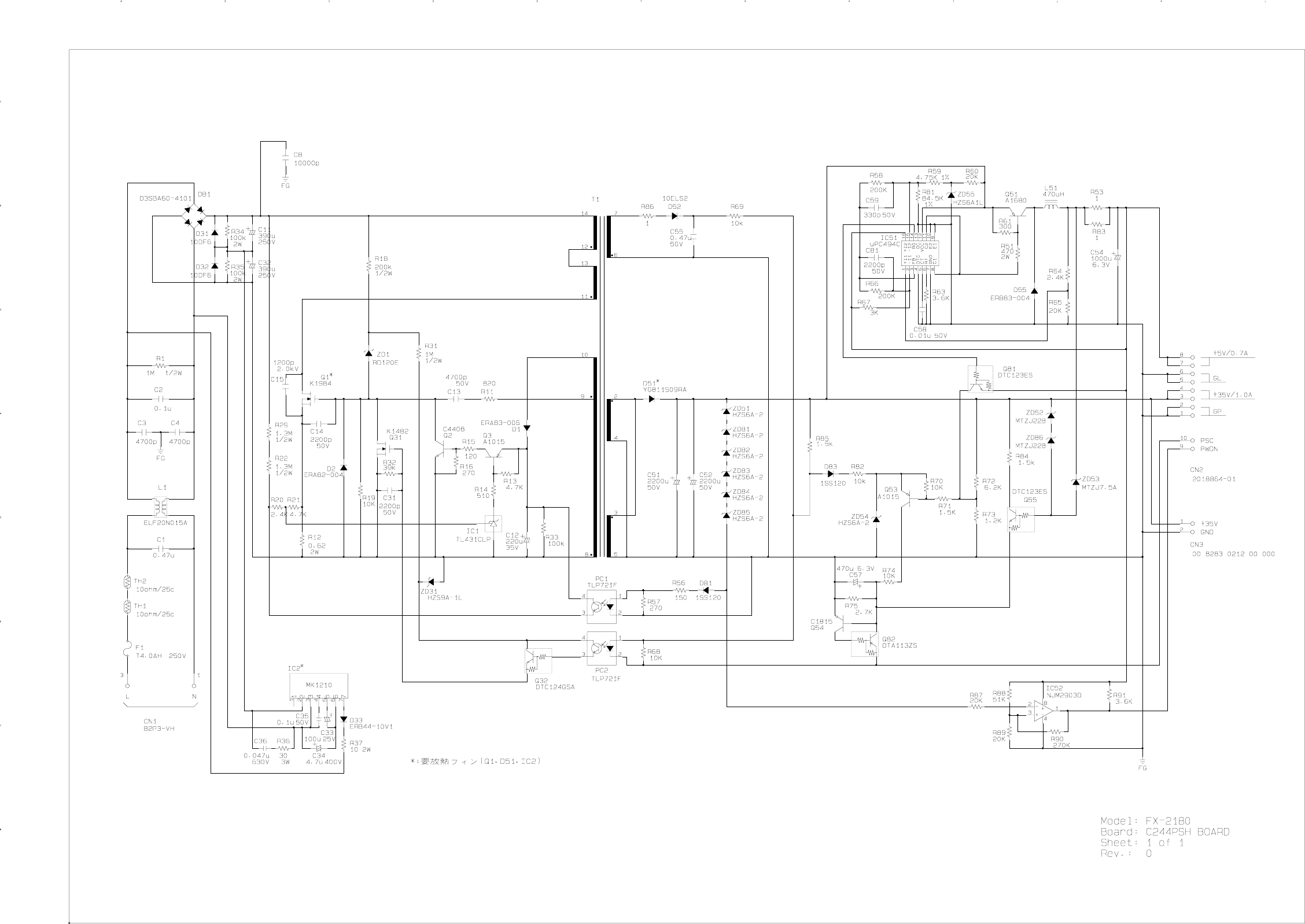
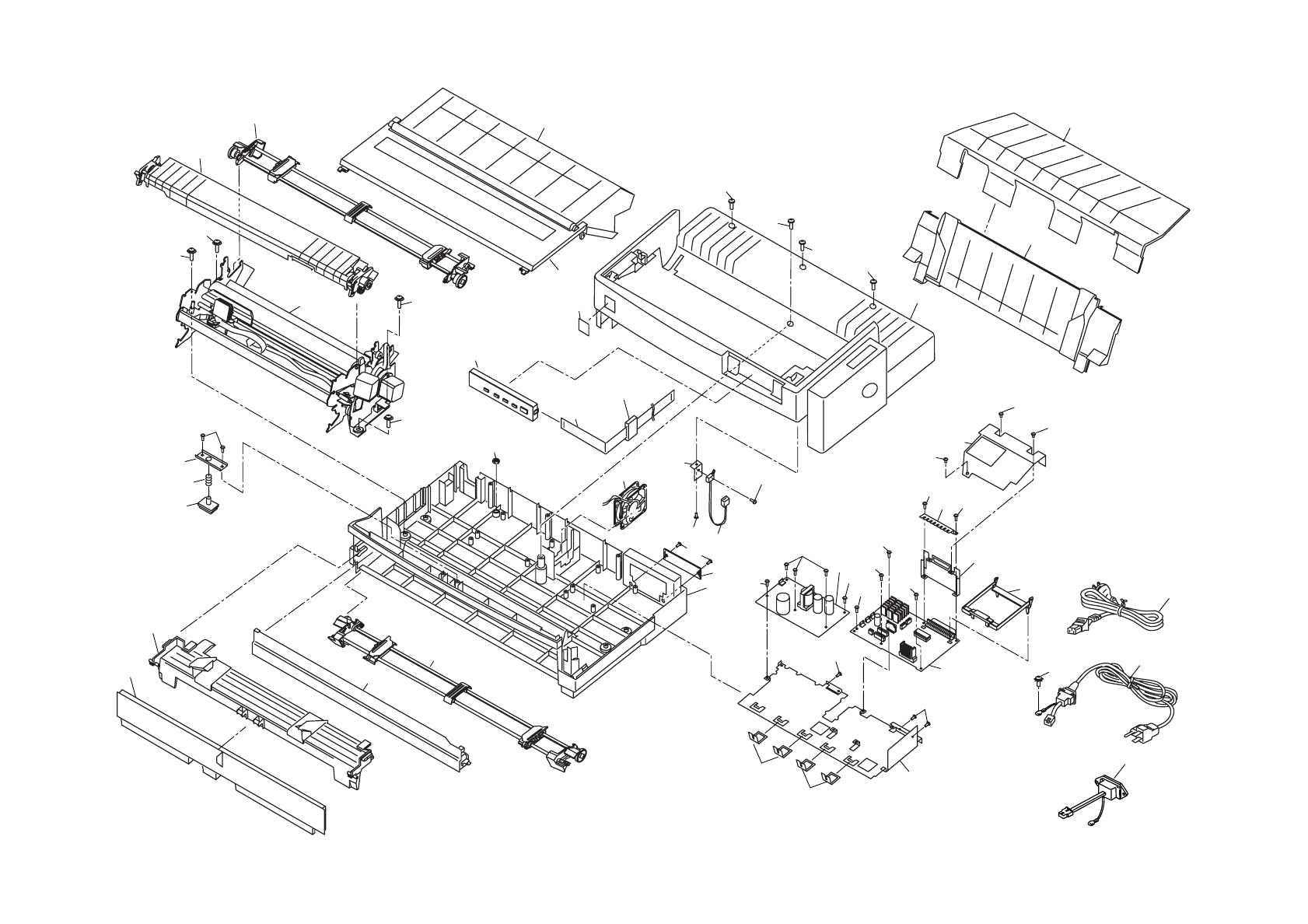
EXPLODED DIAGRAM FOR FX-2180(1)
128
128
122
113 127
137
117
200
109
104
450
400
401
400
122
112
112
110
100
107
621
133
128
116
111
127
122
300
127
127
127
127 127
127
632
106
121
121
380
121
129
102
125
119
124
330
126
103
126
126
541
555
126
118
115
114
500 120
643
105
101
130
123
124
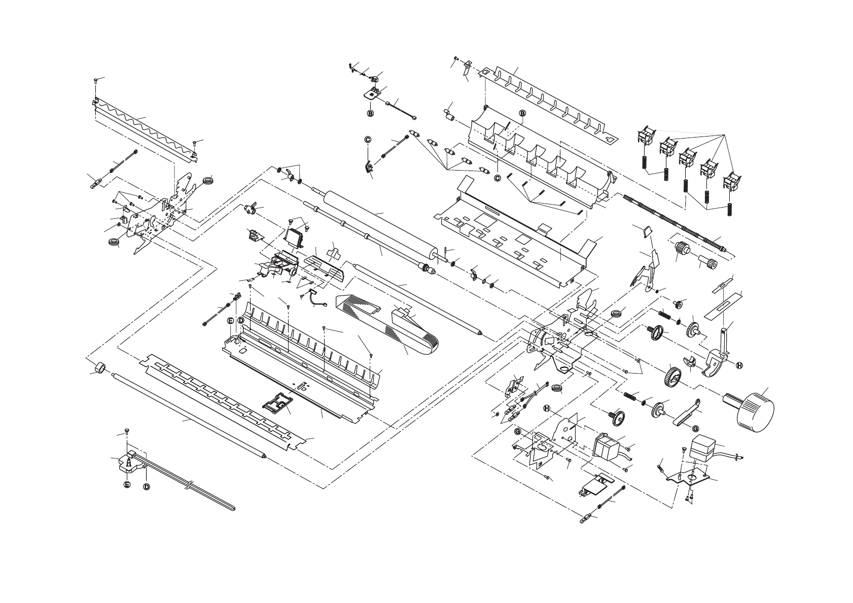
617
524
631
609
636
611
611
511
580
636
591
603
571
636
601 637 595
602
593
590
108
586
608
501 643
598
594
526
535
535
528
639
607
599
606
531
620
533
527
530
525
585
584
578
532
634
638 572597
637
570
600
583
569
650
581
568
567
630
588
565
575
614
604
574
589
538
502
577
643
610
636
636
636
573
524
631
605 521
643
615
524
613
640
587
503
552
626
529
EXPLODED DIAGRAM FOR FX-2180(2)
592
592
592
592
638
644 534
566
522
536
523
635
582
539 576
635
596
601 637 595
504
641
579
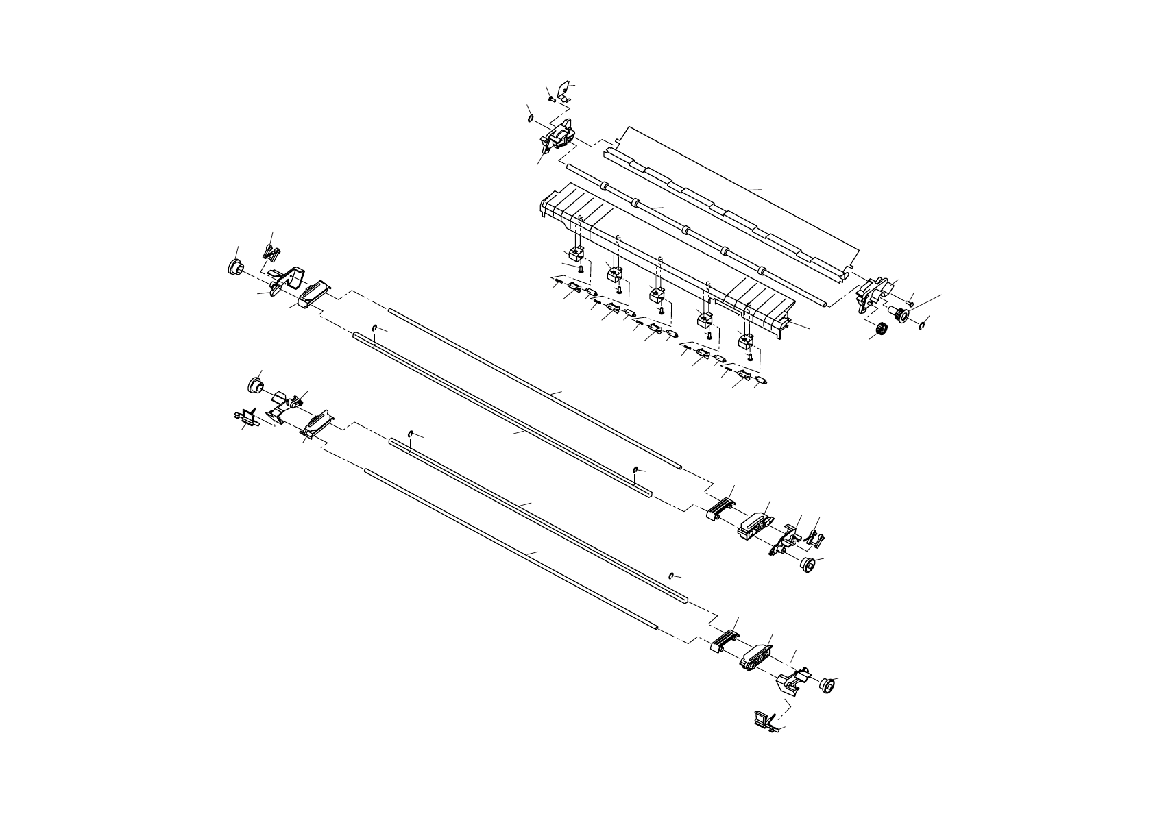
551
549
547
543
550
542
546
551
548
545
544
544
633
633
551
625
547
543
550
542
546
551
624
545
633
633
557
564
559
639
638
639
638
612
561
562
558
629
642 629
642 629
642 629
642 629
642
628 560
627 628 560
627 628 560
627 628 560
627 628 560
627
556
EXPLODED DIAGRAM FOR FX-2180(3)
