Ericsson Antenna Technology Germany 86010148V01 Positioning tool for antennas User Manual Datenblatt 9364624a 86010148V01
KATHREIN-Werke KG Positioning tool for antennas Datenblatt 9364624a 86010148V01
user manual
Type No. 86010148V01
Protocols compliant to AISG 1.1 and 3GPP/AISG 2.0
Logical interface ex factory 1) 3GPP/AISG 2.0
Input voltage range 10 ... 30 V (pin 1, pin 6)
Power consumption < 1 W (stand by); < 10 W (motor activated)
Connectors 2) 3) 2 x 8 pin connector according to IEC 60130-9; according to AISG
Daisy chain in: male; Daisy chain out: female
Hardware interfaces RS 485A/B (pin 5, pin 3);
power supply (pin 1, pin 6); DC return (pin 7);
according to AISG / 3GPP
Adjustment time (full range) 40 sec (typically, depending on antenna type)
Adjustment cycles > 50,000
Temperature range –40 °C … +60 °C
Protection class IP 24
Lightning protection AISG interface (each pin)
2.5 kA (10/350 µs)
8 kA (8/20 µs)
Housing material Profi le: Aluminum anodized; cover: Aluminum die cast coated
Weight 455 g (0.99 lbs)
Packing size 245 x 93 x 102 mm, (9.6 x 3.6 x 4 inches)
Dimensions (H x W x D) 177.5 x 59.5 x 49.5 mm, (7.0 x 2.3 x 1.9 inches)
1) The protocol of the logical interface can be switched from 3GPP/AISG 2.0 AISG 1.1 to with a vendor
specifi c command. Start-up operation of the RCU is only possible in a RET system supporting 3GPP/
AISG 2.0!
The protocol can also be changed as follows: 3GPP to AISG 1.1: Enter “AISG1” into the additional data
fi eld “Installer’s ID” and perform a layer 2 reset or a power reset. AISG 1.1 to 3 GPP: Enter “3GPP” into
the additional data fi led “Installer’s ID” and perform a layer 7 reset or a power reset. After switching the
protocol any other information can be entered into the “Installer’s ID” fi eld.
Please note:
If the Primary of the RET system doesn’t support the standard of the ‘logical interface ex factory’, the RCU
must be switched to the appropriate standard of the Primary before installation. Please contact Kathrein
for further information.
2) The tightening torque for fi xing the connector must be 0.5 – 1.0 Nm (‘hand-tightened’). The connector
should be tightened by hand or using the torque screwdriver (85010080) as described in the connecting
cable data sheet (85010007, ...)
3) The RCU get‘s the information stored in the antenna after power on automatically if a corresponding
antenna is used. It is not necessary to confi gurate the RCU manually.
Standards: EN 60950-1 (Safety)
EN 60950-22 (Safety – Equipment installed outdoor)
EN 55022 (Emission)
EN 55024 (Immunity)
ETS 300019-1-4 (Environmental)
UL 60950-1; 1st edition
Certifi cation: CE, FCC
Scope of supply: Remote Control Unit
Assembly paste
KATHREIN-Werke KG · Anton-Kathrein-Straße 1-3 · P.O. Box 10 04 44 · 83004 ROSENHEIM · GERMANY · Phone +49 8031 184-0 · Fax +49 8031 184-820
www.kathrein.de 86010148V01 Page 1 of 5
936.4624/a Subject to alteration.
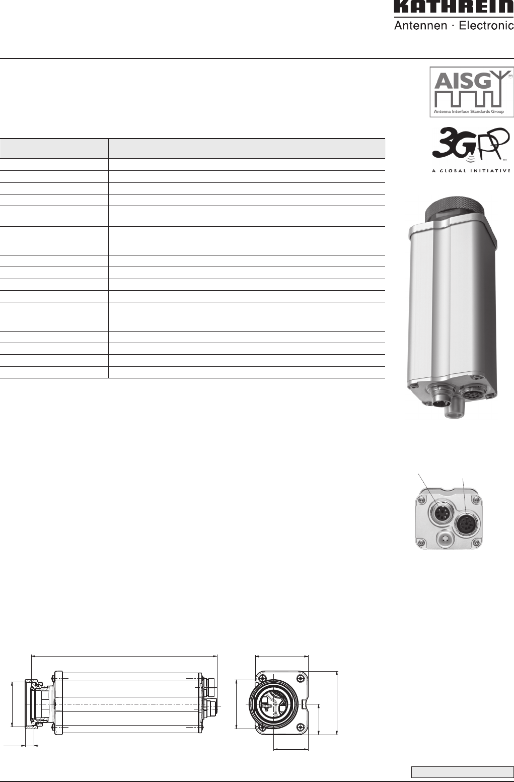
Remote Control Unit (RCU)
Remote Control Unit (RCU) for Kathrein base station antennas with adjustable electrical down-
tilt and appropriate mechanical interface.
● Compliant to AISG 1.1 and 3GPP/AISG 2.0 ● Daisy Chain feasibility
● Compact size ● Suitable for operation under outdoor condition
● Automatic Confi guration
173.6 mm
(6.8ʺ)
33.2 mm
(1.27ʺ)
M42x1.5
28.5 mm
(1.1ʺ)
Ø 46 mm
(Ø 1.8ʺ)
59.5 mm
(2.34ʺ)
49.5 mm
(1.95ʺ)
8 mm
(0.31ʺ)
Daisy chain in
(male)
Daisy chain out
(female)
Bottom view of RCU
Please note: Additional grounding of the RCU is not required if the RCU is fi xed to an antenna with proper ground-
ing. Please assure that grounding of the antenna has been carried out according to all relevant local
regulations.
Please note: As a result of more stringent legal regulations and judgements regarding product liability, we are
obliged to point out certain risks that may arise when products are used under extraordinary operating
conditions.
The mechanical design is based on the environmental conditions as stipulated in ETS 300 019-1-4 and thereby
respects the static mechanical load imposed on an antenna by wind at maximum velocity. Wind loads are
calculated according to DIN 1055-4. Extraordinary operating conditions, such as heavy icing or exceptional
dynamic stress (e.g. strain caused by oscillating support structures), may result in the breakage of an antenna or
even cause it to fall to the ground. These facts must be considered during the site planning process.
The installation team must be properly qualifi ed and also be familiar with the relevant national safety
regulations.
The details given in our data sheets have to be followed carefully when installing the antennas and
accessories.
The limits for the coupling torque of RF-connectors, recommended by the connector manufacturers must
be obeyed.
Any previous datasheet issues have now become invalid.
KATHREIN-Werke KG · Anton-Kathrein-Straße 1-3 · P.O. Box 10 04 44 · 83004 ROSENHEIM · GERMANY · Phone +49 8031 184-0 · Fax +49 8031 184-820
www.kathrein.de
Page 2 of 5 86010148V01
936.4624/a Subject to alteration.
Remote Control Unit (RCU)
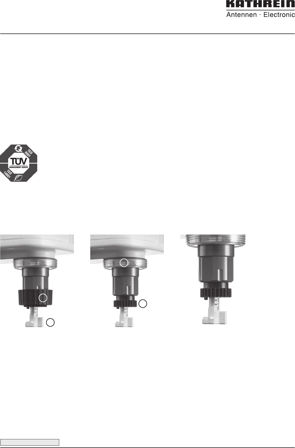
Description of the adjustment mechanism (protective cap removed):
➀ Adjustment wheel with twist-lock
function.
➁ Downtilt spindle with integrated
scale.
➀ Thread for fi xing the pro tective
cap or the RCU (Remote Control
Unit).
➁ Gearwheel for RCU power drive.
To set the downtilt angle exactly,
you must look horizontally at the
scale. The lower edge of the gear-
wheel must be used for alignment.
1
2
2
1
KATHREIN-Werke KG · Anton-Kathrein-Straße 1-3 · P.O. Box 10 04 44 · 83004 ROSENHEIM · GERMANY · Phone +49 8031 184-0 · Fax +49 8031 184-820
www.kathrein.de 86010148V01 Page 3 of 5
936.4624/a Subject to alteration.
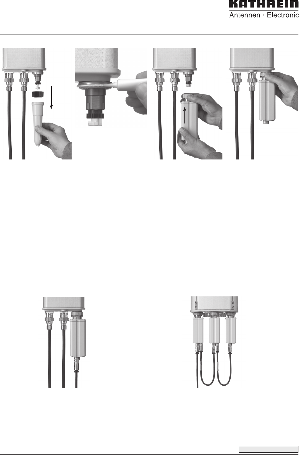
Instructions for RCU Installation
Attaching the RCU (Remote Control Unit) for remote-controlled downtilt adjustment:
Twist off the protective cap com-
pletely from the antenna.
Check the proper function of
the phase shifter over the entire
adjustment range by twisting
the adjustment wheel in such
a way, that the spindle moves
completely in and out.
Reset the downtilt to 0 degree.
Completely remove the black
adjustment wheel by simply
pulling it downwards.
Clean the thread surface.
Apply the assembly-paste evenly
onto the full circumference of the
thread as illustrated in the fi gure.
Note!
Avoid ingestion and contact
with eyes.
In case of contact with eyes
rinse thoroughly with plenty of
water. In case of irritation seek
medical advice.
Avoid long-term contact with
skin.
In case of contact with skin
wash off with soap and water.
For further information
please read the safety data-sheet
‘Klüberplex AG 11-461’
by company
Klüber Lubrication München KG
Geisenhausenerstraße 7
D-81379 München
http://www.klueber.com
Push the attachment nut of the
RCU down towards the housing.
Place the RCU carefully over the
adjustment spindle, observ ing the
correct alignment of the RCU with
regards to the antenna, i.e. the fl at
surfaces of the attachment fi xture
on the antenna side and those
inside the RCU housing must lie
fl at against each other.
Push-up the RCU carefully to the
stop at the antenna.
Please note!
Do not twist the RCU during
attaching to the antenna, as
this may damage the adjust-
ment spindle.
Tighten the RCU attachment nut
using a torque-wrench; wrench
width = 41 mm,
min. torque = 15 Nm,
max. torque = 18 Nm.
Connect the RCU control cable
immediately after attachment of
the RCU. The tightening torque
for fi xing the control cable connec-
tor must be 0.5 – 1.0 Nm (‘hand-
tightened’).
Please note!
In cases where a mechanical
downtilt unit is installed, this
must not be set for a downtilt of
more than 14 degrees.
Connecting the control cables:
Connect a control cable to the daisy chain input of
the RCU.
The tightening torque for fi xing the connector must be
0.5 – 1.0 Nm (‘hand-tightened’).
The connector should be tightened by hand only!
Please note: If the daisy chain output is not used,
do not remove the protection cap.
For daisy chain operation, remove the protection cap
and attach a control cable to interconnect with the
daisy chain input of the subsequent RCU.
Please note: Do not remove the protection cap on
the daisy chain output of the last RCU device.

KATHREIN-Werke KG · Anton-Kathrein-Straße 1-3 · P.O. Box 10 04 44 · 83004 ROSENHEIM · GERMANY · Phone +49 8031 184-0 · Fax +49 8031 184-820
www.kathrein.de
Page 4 of 5 86010148V01
936.4624/a Subject to alteration.
FCC – Statements
FCC – Statements
FCC § 15.19
This device complies with Part 15 of the FCC rules. Operation is subject to the following two
conditions: (1) This device may not cause harmful interference, and (2) this device must accept any
interference received, including interference that may cause undesired operation.
FCC § 15.105
Note: This equipment has been tested and found to comply with the limits for a Class B digital device,
pursuant to part 15 of the FCC Rules. These limits are designed to provide reasonable protection
against harmful interference in a residential installation. This equipment generates, uses and can
radiate radio frequency energy and, if not installed and used in accordance with the instructions, may
cause harmful interference to radio communications. However, there is no guarantee that
interference will not occur in a particular installation. If this equipment does cause harmful
interference to radio or television reception, which can be determined by turning the equipment off
and on, the user is encouraged to try to correct the interference by one or more of the following
measures:
—Reorient or relocate the receiving antenna.
—Increase the separation between the equipment and receiver.
—Connect the equipment into an outlet on a circuit different from that to which the receiver is
connected.
—Consult the dealer or an experienced radio/TV technician for help.
Canada CNR-Gen Section 7.1.3
This device complies with Industry Canada licence-exempt RSS standard(s). Operation is subject to
the following two conditions:(1) this device may not cause interference, and (2) this device must
accept any interference, including interference that may cause undesired operation of the device.
Le présent appareil est conforme aux CNR d'Industrie Canada applicables aux appareils radio
exempts de licence. L'exploitation est autorisée aux deux conditions suivantes : (1) l'appareil ne
doit pas produire de brouillage, et (2) l'utilisateur de l'appareil doit accepter tout brouillage
radioélectrique subi, même si le brouillage est susceptible d'en compromettre le fonctionnement.
ICES-003
This Class B digital apparatus complies with Canadian ICES-003.
Cet appareil numérique de la classe B est conforme à la norme NMB-003 du Canada.
FCC § 15.21 (Warning Statement)
[Any] changes or modifications not expressly approved by the party responsible for compliance could
void the user’s authority to operate the equipment.
KATHREIN-Werke KG · Anton-Kathrein-Straße 1-3 · P.O. Box 10 04 44 · 83004 ROSENHEIM · GERMANY · Phone +49 8031 184-0 · Fax +49 8031 184-820
www.kathrein.de 86010148V01 Page 5 of 5
936.4624/a Subject to alteration.
FCC – Statements
Compliance Information Statement
(Declaration of Conformity Procedure)
Responsible Party: Kathrein Inc., Scala Division
Address: PO Box 4580, Medford Oregon . 97501
Telephone: (+01)541 779 6500
Type of Equipment:
Model Name: Remote Control Unit (RCU)
FCC ID SP3-86010148V01