Ericsson LG IP8830 IP Phone User Manual Regulatory and Safety Information 1 0 indd
Ericsson-LG Co., Ltd. IP Phone Regulatory and Safety Information 1 0 indd
User manual
E-911 and This Phone’s Use with Multi-Line Telephone
Systems
Please note that the use and operation of this phone as
part of a multi-line telephone system (MLTS) may be sub-
ject to state and/or federal E-911 MLTS laws that require
the MLTS to provide a caller’s telephone number, exten-
sion, and physical location to applicable state and/or lo-
cal emergency services when a caller initiates a 911 call.
This phone does not provide a caller’s telephone number,
extension, or physical location information to emergency
services when a caller dials 911, and compliance with state
and/or federal E-911 MLTS laws is the sole responsibility of
the purchaser of this phone.
Regulatory Information and Disclaimers
“Privacy of communications may not be ensured when us-
ing this telephone”.
Any changes or modifications made to this device that are
not expressly approved by the manufacturer may void the
user’s authority to operate the equipment. The Manufactur-
er is not responsible for any radio or television interference
caused by unauthorized modification of this device, or the
substitution or attachment of connecting cables and equip-
ment other than those specified by the manufacturer. It is
the responsibility for the user to correct any interference
caused by such unauthorized modification, substitution or
attachment.
The manufacturer and its authorized resellers or distribu-
tors will assume no liability for any damage or violation of
government regulations arising from failure to comply with
these guideline.
Pursuant to Part 15 of the Federal Communications
Commission(FCC) Rules, the user is cautioned that chang-
es or modifications not expressly approved by LG-Nortel.
Could void the user’s authority to operate this equipment.
Important Safety Instructions
USA-FCC (Federal Communications Commission)
Statement
This device complies with Part 15 of the FCC Rules. Op-
eration is subject to the following two conditions:
FCC Interference Statement
Note: This equipment has been tested and found to com-
ply with the limits for a Class B Device, pursuant to Part
15 of the FCC Rules. These limits are designed to provide
reasonable protection against harmful interference in a
residential installation. This equipment generates, uses
and can radiate radio frequency and, if not installed and
used in accordance with the instructions, may cause harm-
ful interference to radio communications. However, there
is no guarantee that interference will not occur in a par-
ticular installation. If this equipment does cause harmful
interference to radio or television reception, which can be
determined by turning the equipment off and on, the user
is encouraged to try to correct the interference by one or
more of the following measures:
Compliance Statement for Canada
This Class B digital apparatus complies with Canadian
ICES-003.
Cet appareil numérique de la classe B est conforme à la
norme NMB-003 du Canada.
This device complies with Class B Limits of Industry Cana-
da. Operation is subject to the following two conditions;
European Union Declarations of Conformity
LG-Nortel Co. Ltd. declares that the equipment specified in
this document, which bears the “CE” mark, conforms to the
European Union Radio and Telecommunications Terminal
Equipment Directive (R&TTE 1999/5/EC), including Elec-
tromagnetic Compatibility Directive (2004/108/EC) and
Low Voltage Directive (2006/95/EC).
The product fulfills the essential requirements of the har-
monized standards shown above.
Product Safety Instructions
This product complies with and conforms to the following
international Product Safety standards as applicable:
Safety of Information Technology Equipment, IEC 60950-1,
including Relevant national deviations as listed in Compli-
ance with IEC for Electrical Equipment (IECEE) Safety of
Information Technology Equipment, CAN/CSA-C22.2 No.
60950-1/UL 60950-1
Regulatory and Safety Information
Please save these instructions and read carefully
Printed In Thailand. Copyright © 2008 LG-Nortel Co.Ltd. All rights reserved.
P/NO: MMBB1234567,1.0
This device may not cause harmful interference, and
This device must accept any interference received, in-
cluding interference that may cause undesired opera-
tion.
1
2
Reorient or relocate the receiving antenna.
Increase the separation between the equipment and
receiver.
Connect the equipment into an outlet on a circuit differ-
ent from that to which the receiver is connected.
Consult the dealer or an experienced radio/TV techni-
cian for help.
1
2
3
4
This device may not cause harmful interference, and
This device must accept any interference received, in-
cluding interference that may cause undesired opera-
tion.
1
2
Before connecting or using your new phone, take a
moment to consider safety and reliability. Use common
sense when locating, connecting and using you Phone.
Locate on a dry level surface away. Keep the phone away
from the edges of the surface to avoid the potential of
a fall.
Locate cables to avoid potential for damage. For exam-
ple, do not locate under rugs or carpet as damage may
result from foot traffic or heavy objects. Also, do not lo-
cate cables between the desktop and walls where they
may be crushed, damaging the insulation.
Check the cables regularly and, if damage is noted, dis-
connect your phone. Contact your local representa-tive
for a replacement.
Should liquid spill on the phone, disconnect the unit from
power and the network.
Do not use during lightning storms. Lightning presents a
potentially lethal shock hazard.
Clean the phone with a soft dry cloth; do not use liquid
cleaners.
Always use caution when connecting to AC power. Use
only with a properly grounded standard AC power outlet.
•
•
•
•
•
•
•
•
Regulatory and Safety Information 1.0.indd 1Regulatory and Safety Information 1.0.indd 1 2008-01-24 오후 3:14:552008-01-24 오후 3:14:55
IP8800 Series Quick Installation Guide
Attaching the foot stand
Decide if you will be attaching the foot stand angle either 35 degree or 55 degree.
If you require a Global Power Supply for your IP Phone, use the LG-Nortel approved global power supply.
This document provides information about the IP8820, IP8830, and IP8840. You can download all required docu-
ments at www.lg-nortel.com.
IP8830 Series Quick Installation Guide
Before you start
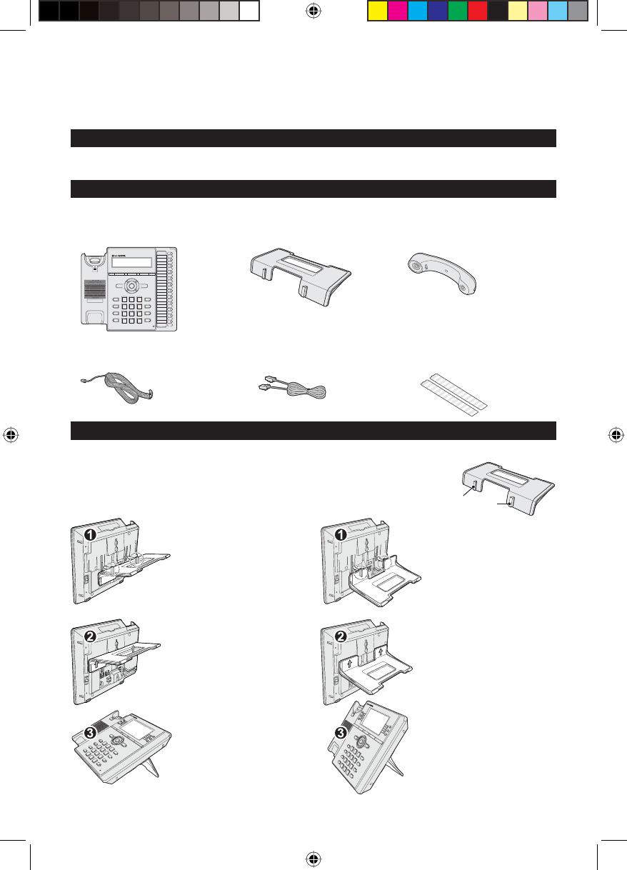
• IP Phone (IP8830) • Foot Stand • Handset
The following items are included in your IP8800 Series package. Before installation, ensure that you have the
following package contents:
Package contents
• Handset Cord • 2.0m CAT5 Ethernet Cable • Number Plates (2ea)
(only for IP8820/IP8830)
To install this IP Phone correctly, please follow the procedures. Please refer to the figures as shown below.
Installation
Align the top tabs on the
foot stand with the slots on
the back of your IP Phone.
Please refer to the figures
left for the correct place-
ment of the foot stand.
And then, move the foot
stand upward until it clicks
into place.
The IP Phone sits at a 35
degree angle.
Turn the foot stand upside
down; Align the top tabs
on the foot stand with the
slots on the back of your IP
Phone. Please refer to the
figures left for the correct
placement of the foot stand.
And then, move the foot
stand upward until it clicks
into place.
The IP Phone sits at a 55
degree angle.
Top Tabs
IP-88XX Quick Installation Guide 1.2.indd 1IP-88XX Quick Installation Guide 1.2.indd 1 2008-06-11 오후 1:46:032008-06-11 오후 1:46:03
IP8800 Series Quick Installation Guide
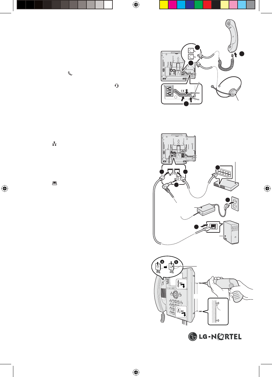
Connecting Handset and Headset
4
2
3
1
Wall-mounting the IP Phone (Optional)
Note: Ensure all cables are routed and if necessary, that power
is installed.
Connecting Network and Power
Note: Your IP Phone supports both AC power and Power over Ethernet (PoE), (more than class 2). To use AC
power, use only the LG-Nortel Approved AC power adapter (SSAD9025601), which you can order separately. To use
PoE, your connected LAN must support PoE and an AC power adapter is not required.
Printed In Thailand. Copyright © 2008 LG-Nortel Co.Ltd. All rights reserved.
P/NO: MMBB9218101,1.0
For more detailed installation instructions, see IP8820/IP8830/IP8840 Installation at www.lg-nortel.com.
(Optional)
12
3
5
6
4
Wiring
Channel
Optional PC
Connection
Ethernet Hub/Switch or
IEEE 802.3af Hub/Switch
Optional Power Adapter
Connection: 48V DC
10cm
2.5mm
Wall
Wall
Wall
Handset
Retainer Tap
Plug one end of the handset cord (short straight section)
into the handset.
Plug the other end of the handset cord (long straight sec-
tion) into the handset jack on the back of the IP Phone
marked with the symbol.
(Optional) Plug one end of the cord into the headset jack on
the back of the IP Phone marked with the symbol.
From a small bend in the cord, thread the cord through the
wiring channel.
1
2
3
4
Plug one end of the supplied LAN Ethernet cable into the
LAN Ethernet port on the back of your IP Phone marked
with the symbol.
Plug the other end of the cable into your LAN Ethernet
connection. (Do not extend the LAN Ethernet cable to the
outside of the building.)
(Optional) If you are connecting your PC Ethernet through
the IP Phone, plug one end of the LAN Ehternet cable into
the PC Ethernet port on the back of your IP Phone marked
with the symbol.
(Optional) Plug the other end of the cable into your LAN
Ethernet connection.
(Optional) Connect the AC power adapter (not suppplied)
to the AC adapter jack on the back of your IP Phone. Fas-
ten the cord with a hook to prevent it from being discon-
nected.
(Optional) Plug the AC power adapter into the nearest AC
power outlet. The phone will start up.
1
2
3
4
5
6
Remove the foot stand.
Pull out the handset retainer tap out of the slot. Turn around
and place in the opposite direction. Then hang up the hand-
set.
Make a small mark on the wall where you want the top ke-
hole slot to align and insert a screw (not provided) so that it
protrudes slightly 2.5mm from the wall.
Measure a straight line down 10cm from the mark, and insert
a screw (not provided).
Align the keyholes on the back of the IP Phone with the screws
in the wall, and then slide the IP Phone down on the screws
to secure the IP Phone.
1
2
3
4
5
IP-88XX Quick Installation Guide 1.2.indd 2IP-88XX Quick Installation Guide 1.2.indd 2 2008-06-11 오후 1:46:082008-06-11 오후 1:46:08
IP8800 Series Expansion Modules Quick Installation Guide
3
2
5
6
4
This document provides information about the LCD Expansion Module: 12-Key Self-Labeling and the LED
Expantion Module: 12-Key Paper Label. You can download all required documents at www.lg-nortel.com.
Expansion Modules for IP883 0 Series
Descripton
The Expansion Modules for IP Phone 8800 Series provide 12 additional line/programmable feature keys for
your IP Phone. You can place the IP Phone and Expansion Modules on your desktop or you can wall-mount the
IP Phone and Expansion Modules.
Up to one LCD or LED Expansion Modules are supported on a single IP Phone. The Expansion Modules are
supported on the IP Phone 8820, 8830 and 8840.
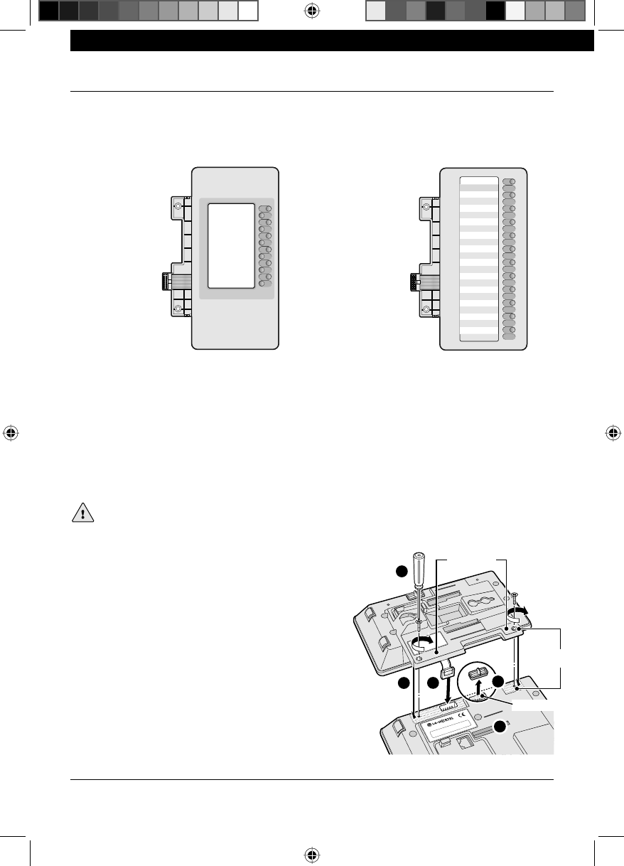
LCD Expansion Module:
12-Key Self-Labeling LED Expansion Module:
12-Key Paper Label
Your Expansion Modules
Installation
Caution! To avoid damaging equipment, remove the power from the IP Phone before connecting an
Expansion Module. To install this Expansion Module correctly, please follow the procedures.
Installing the Expansion Modules
Remove power from the IP Phone.
Remove the foot stand from the IP Phone.
At the back of the IP Phone, remove the rubber plug from
the Accessory Expansion Module (AEM) port.
Plug the 12- pin cable from the Expansion Module into the
AEM port on the back of the IP Phone.
Place the connecting arm of the Expansion Module behind
the IP Phone and align the Expansion Module connect-
ing holes with the connecting holes on the back of the IP
Phone.
Turn the screw to the right to connect the Expansion Mod-
ule and IP Phone firmly together.
1
2
3
4
5
6
AEM Port
Connecting
arms
Connecting
holes
IP-88XX Expansion Moudle Installation Guide 1.0.indd 1IP-88XX Expansion Moudle Installation Guide 1.0.indd 1 2008-04-23 오후 4:41:192008-04-23 오후 4:41:19
IP8800 Series Expansion Modules Quick Installation Guide
P/NO: MMBB9219501,1.0
Align the Top tabs on the foot stands with the slots on the
back of the Expansion Module and IP Phone.
And then, move the foot stands upward until it clicks into
place.
For more detailed installation instructions, see the IP8800
Series Quick Installation Guide.
Attaching the foot stands
Set the Expansion Module and IP Phone foot stands to the same angle.
Completing the installation
Connect power to the IP Phone. The IP Phone and Expansion Modules power up. The Expansion Modules
use the electrical connection of the IP Phone for power. Expansion Modules do not have their own power
source.
After you power up your IP Phone, the Expansion Module LEDs or LCD display icons flash (depending on
Expansion Module type), until communication with the IP Phone is established. For information about pro-
gramming features, see the IP8800 Series Installer Guide at www.lg-nortel.com.
1
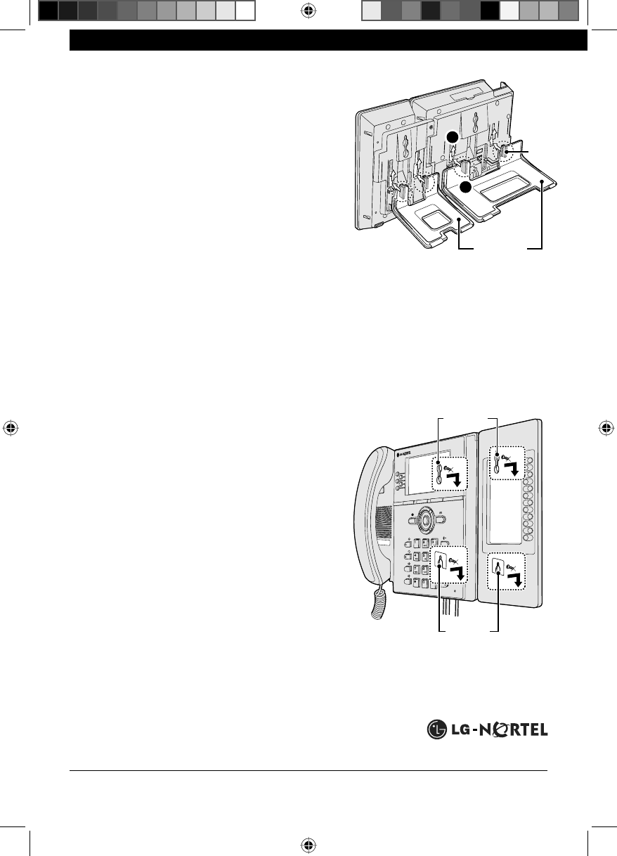
Wall-mounting the IP Phone and Expansion Modules
Remove the foot stands from the IP Phone and Expansion
Module.
Ensure that the cables are properly connected to the IP
Phone, and then connect the Expansion Module to your IP
Phone, as previously described.
Wall-mount the IP Phone and Expansion Module using
the keyholes in the back of the IP Phone and Expansion
Module.
For more detailed installation instructions, see IP8800 Se-
ries Quick Installation Gudie at www.lg-nortel.com.
Printed In Thailand. Copyright © 2008 LG-Nortel Co.Ltd. All rights reserved.
1
1
2
Top Tabs
Foot stands
Keyholes
Keyholes
2
1
2
3
IP-88XX Expansion Moudle Installation Guide 1.0.indd 2IP-88XX Expansion Moudle Installation Guide 1.0.indd 2 2008-04-23 오후 4:41:202008-04-23 오후 4:41:20