Ericsson LG NS161GNN-O WDM-PON ONT User Manual
Ericsson-LG Co., Ltd. WDM-PON ONT
User Manual

TurboLIGHT16
Hardened ONT Unit
(NS 16 1G NN-O)
Please read this manual carefully before operating your set.
Retain it for future reference.
C O N T E N T S
3 Product and personal safety guidelines
8 Regulatory information
11 About NS 16 1G NN-O
15 Checking package contents
16 Installing NS 16 1G NN-O
18 Setting NS 16 1G NN-O
NS 16 1G NN-O
Product and personnel safety guidelines
This section contains safety guidelines that you must follow for personal safety and
to operate the equipment correctly.
LG-Nortel documentation contains precautionary messages and safety procedures
that refer to specific tasks or conditions. You must read and follow all precautionary
messages before you start to work on the equipment.
Audience
Personnel working directly on equipment must be
• trained, authorized, and qualified to carry out the tasks required
• able to follow safety guidelines specific to the product and all local customerspecific
safety procedures
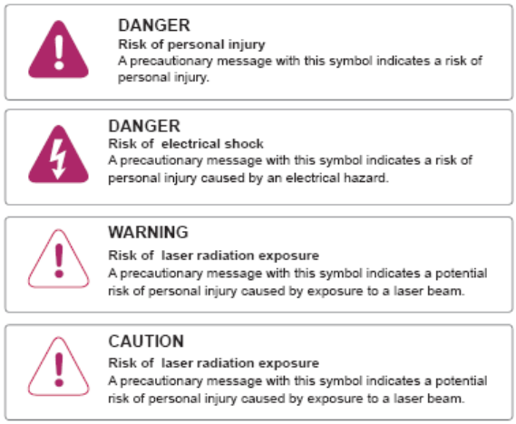
Precautionary messages
To prevent personal injury, equipment damage, and service interruptions, you must
follow all precautionary messages in Nortel documentation and all local safety
standards required by your service provider.
The following precautionary messages appear in Nortel documentation:

Safety standards
LG-Nortel products conform to all relevant safety standards. NS 16 1G NN-O
complies with the following safety standards:
• IEC/EN 60950-1:2001+A11:2004—Information technology equipment - Safety,
Part 1 : General requirements
• IEC 60825-1:2001 and IEC 60825-2:2004—Safety of Laser Products
• FDA 21 CFR 1040—Performance Standards for Light-Emitting Products
Laser radiation—eye safety hazards
LG-Nortel optical products use laser or light-emitting diode (LED) sources that
emit light energy into optical fibers. This energy is within the red (visible) and
infrared (not visible) areas of the electromagnetic spectrum. FDA 21 CFR 1040
Performance Standards for Light-Emitting Products
Laser radiation hazards
When operating the product normally, with all optical connectors in position and
correctly terminated, the optical radiation is completely enclosed. The system is
a Class 1(IEC)/Class I (FDA) product, regardless of the power transmitted within
the optical fiber.
If you have unterminated optical cables (breaks in the fiber-optic cable or
disconnected connectors) the output from circuit packs containing optical
transmitters does not exceed Class 1 (IEC)/Class I (FDA) and is therefore
considered safe under all reasonably foreseeable conditions.
The following text includes additional information on the laser for the NS 16 1G
NN-O.
Using optical fibers
All activity described herein regarding the optical interface of the NS 16 1G NN-O
is intended only for trained personnel operating under the direction of the service
provider. Users and homeowners should not attempt to access or disconnect the
optical interface or damage the optical cable. Consult with the service provider
before undertaking any action involving the optical interface.
Laser wavelength 1534 - 1560 nm
Maximum laser output power <= 5 mW
Standards: IEC 60825-1:2001 Edition 1.2
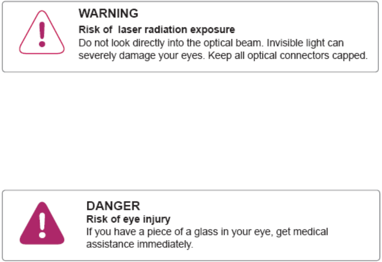
Handling optical fibers
When you work with optical fibers, you must take the following general precautions:
• Wear safety glasses when you install optical fibers.
• Do not look into the opening of an optical fiber, or the opening of an optical fiber
connector, if the optical fiber is active or the unit has the power turned on.
• Avoid direct exposure to optical fiber ends or optical connector ends where you
can access the laser signal directly.
• Clean your hands after you handle optical fibers. Small pieces of glass are not
always visible and can damage your eyes.
!
• Do not handle pieces of optical fiber with your fingers. Use tweezers or adhesive
tape to lift and discard any loose optical fiber ends.
• Wear rubber gloves when you clean optical connectors. The gloves prevent direct
contact with the isopropyl alcohol and prevent contamination of the ferrules with
skin oils.
• Place all optical fiber clippings in a plastic container provided for that purpose.
• Handle optical fibers with caution. Place the optical fibers in a safe location during
installation.
• Protect all optical fiber connectors with clean dust caps at all times.
• Follow the manufacturer instructions when you use an optical test set. Incorrect
calibration or control settings can create hazardous levels of radiation.
Splicing optical fibers
When you must look at a spliced optical fiber with a small magnifier, take the
following precautions:
• Power off all laser sources to the optical fiber or disconnect the remote optical
fiber end from the laser sources before you start splicing. Make sure that all laser
sources remain disconnected or have the power turned off.
• Disconnect all optical test sets from the optical fiber before you start splicing. The
connections can be local or remote.
• Use only the optical instruments approved by your company.

Repairing optical fibers
When an accidental break occurs in the optical fiber, do the following:
• Report the location of the damaged optical fiber to both the service provider and
the field repair personnel.
• Power down all laser sources to the optical fiber or disconnect the remote optical
fiber end from the laser sources.
Working with power
Other Warnings and cautions
WARNINGS

CAUTIONS
Warranty: Customers can receive repair services for this product under
specified conditions. This warranty does not cover failure or damage of
the product caused from, using a power adapter other than the one
provided, PC failures, data loss, or negligent treatment of the product.
Regulatory information
This chapter contains the following information:
• a list of global technical standards (electromagnetic compatibility, safety) to which
the NS 16 1G NN-O complies
• a country-by-country list of specific regulatory text required by national authorities
• information on the regulatory labels affixed to the product (artwork and location
on the product)
The list of global technical standards provided in this chapter is not exhaustive.
The standards listed are generally regarded as the primary applicable
electromagnetic compatibility (EMC) and safety standards. The conformity status
on additional national and international standards not listed in this section can be
provided upon request.
Compliance to applicable technical standards and
regulations
The NS 16 1G NN-O meets or exceeds the following standards and requirements:
• (CFR Title 47, Chapter 1) FCC Part 15, Subpart B, Class B (USA)
• ICES-003, Issue 4, Class B (Canada)
• European Union EMC Directive (2004/108/EC)
• European “Low Voltage” Directive (2006/95/EC)
• EN 55022:2006 - Class B (European Community, Australia and New Zealand)
• EN 55024:1998 +A1:2001 +A2:2003 (European Community)
• EN 300 386 V1.3.3 (European Community, Australia and New Zealand)
• Australian Radiocommunications Labelling (Electromagnetic Compatibility) Notice
2008
• CAN/CSA-C22.2 No. 60950-1 (Canada)
• UL Std No. 60950-1 (USA)
• IEC/EN 60950-1:2001+A11:2004 (European Community)
• IEC/EN 60825-1:2001
• IEC/EN 60825-2:2004
Country-specific regulatory information
Canada
This Class B digital apparatus complies with Canadian ICES-003.
Cet appareil numérique de la classe B est conforme à la norme NMB-003 du
Canada.
United States of America
This equipment has been tested and found to comply with the limits for a Class
B digital device, pursuant to part 15 of the FCC Rules. These limits are designed
to provide reasonable protection against harmful interference in a residential
installation. This equipment generates, uses and can radiate radio frequency
energy and, if not installed and used in accordance with the instructions, may
cause harmful interference to radio communications. However, there is no
guarantee that interference will not occur in a particular installation. If this
equipment does cause harmful interference to radio or television reception,
which can be determined by turning the equipment off and on, the user is
encouraged to try to correct the interference by one or more of the following
measures:
• Reorient or relocate the receiving antenna.
• Increase the separation between the equipment and receiver.
• Connect the equipment into an outlet on a circuit different from that to which
the receiver is connected (consult with the service provider before proceeding).
• Consult the service provider or an experienced radio/TV technician for help.
Repairs to certified equipment should be coordinated by a representative
designated by your service provider. Any repairs or alterations made by the user
to this equipment, or equipment malfunctions, may give the service provider
cause to request the user to disconnect the equipment.
Do not attempt to repair this equipment. If you experience trouble, contact the
service provider.
European Union
The NS 16 1G NN-O conforms with the essential requirements of Directive
2004/108/EC (EMC Directive), Directive 2006/95/EC (Low Voltage Directive)
compliance to the following harmonized standards:
• EN 55022:2006 (Class B)
• EN 55024:1998 +A1:2001 +A2:2003
• EN 300 386 V1.3.3 (Class B, other than telecommunications centres criteria)
• EN 60950-1:2001 +A11:2004
• EN 60825-1:2001
• EN 60825-2:2004
The product bears the CE mark as illustrated in the Figure on page 13.
A signed Declaration of Conformity is available upon request.
Regulatory labels (Safety and EMC)
The following labels have been placed on the system and various field replaceable
units (FRU).
The main product-level regulatory label is located on the bottom of the NS 16
1G NN-O. See the Figure on page 13. The label bears the product name, power
ratings information, certification and other regulatory marks and informational
disclosures required by jurisdictional authorities.
After reading through this User’s Manual, please keep it handy for easy reference.
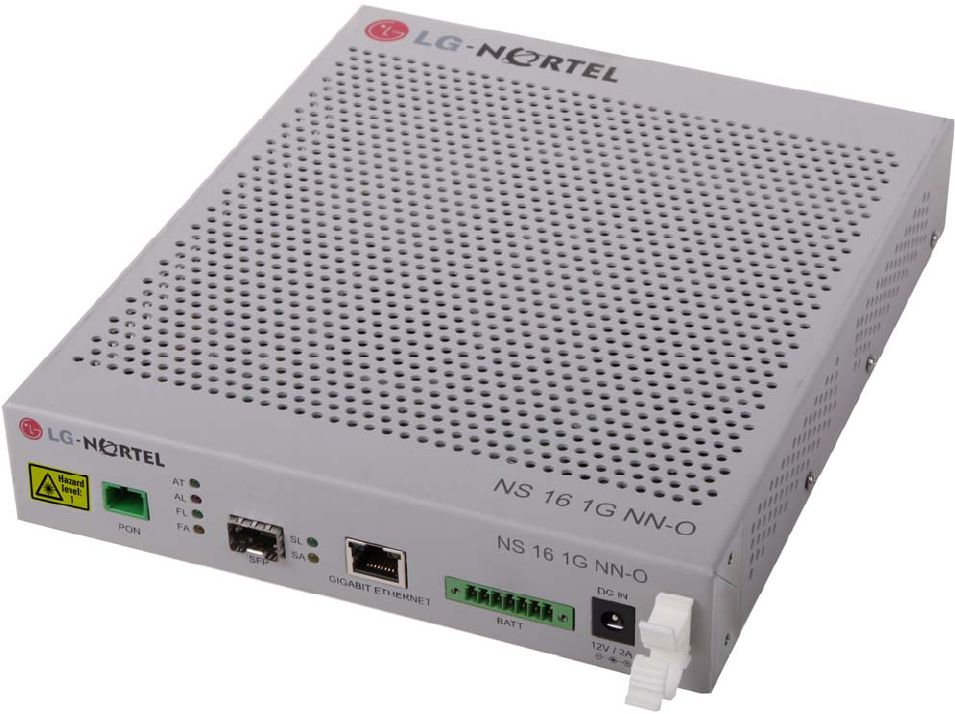
About NS 16 1G NN-O
Thank you for selecting LG-Nortel NS 16 1G NN-O.
The NS 16 1G NN-O is ONT equipment which is located at the Customer premises
end of a TurboLIGHT16 WDM-PON (Wavelength Division Multiplexing - Passive
Optical Network) system.
The NS 16 1G NN-O converts 1.25 Gbps Gigabit Ethernet signal into WDM-PON
optical signal which is transmitted to OLT through RN and getting WDM-PON optical
signal from the RN in convert into 1.25 Gbps Gigabit Ethernet signal.
These products will allow you to use the different services such as VoD (Video on
Demand), EoD (Education on Demand), IP-TV and High speed internet access
available from your provider.
Unit Description
Product front view
NS 16 1G NN-O
○
9 ④ ⑦
① ②
③ ⑧
○
11
○
12 ○
13
⑤
⑩
⑥

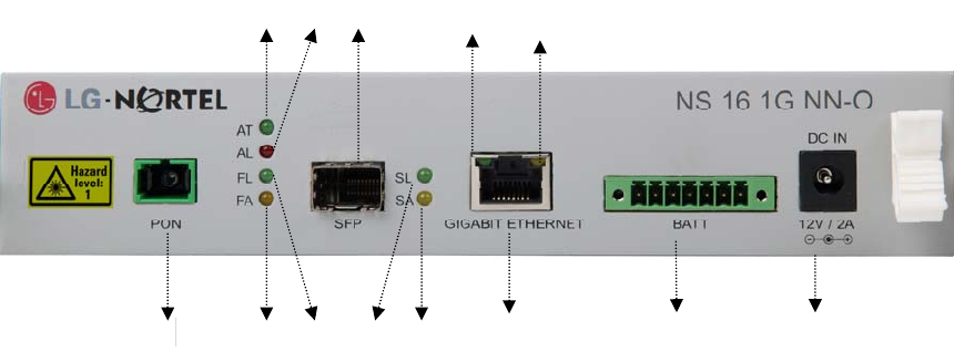
NS 16 1G NN-O Front LED and Descriptions
Number LED Color Status Description
○
1 AT Green On Is lit when link is active
○
2 AL Red On Is lit when alarm occurs
○
3 FL Green On
Is lit when optical link is connected to service provider through
TL16 system
○
4 FA Yellow On
Is lit and blink when the device sends/receives data to/from
equipment of the service provider through TL16 system
○
5 TL Orange On Is lit when Ethernet link is connected
○
6 TA Green On
Is lit and blink when the device sends/receives data to/from
equipment of the service provider.
○
7 SL Green On Is lit when SFP optical link is connected
○
8 SA Yellow On
Is lit and blink when the device sends/receives data to/from
equipment that is connected by SFP
NS 16 1G NN-O Front Panel Port Descriptions
Number Port Type Description
○
9 Optical port SC/APC Adaptor
This port (optical) should be accessed only by the service provider.
It is the access point to the service provider’s network.
○
10 Ethernet port RJ-45
This port is Ethernet port that will connect to user devices
supporting 10/100/1000 Mbps by NS 16 1G NN-O
○
11 SFP port SFP connector
This port to be connected to other Ethernet equipments by SFP
optical module
○
12 Power port DC with monitor
This port is to connect to DC power with power monitor
(battery connection)
○
13 Power port DC to adaptor
This port is to connect to DC power
(power adaptor connection)

NS 16 1G NN-O with lables
Specifications of NS 16 1G NN-O
Item Specification
Dimensions in mm 197.4(w)x232.4(d)x40(h)
Power DC 12V, 2A
Ambient
Temperature
-40℃ to 65℃
Humidity 5% to 90%
Technical
standards
EN 300 386
(Class B, other then Telecom Centres)
FCC part 15 (CFR 47) (Class B)
EN 55022 (Class B) / 55024
Data rate 1.25Gbps
Connectors SC/APC or SFP (optical), RJ45 (Ethernet)
LED indicators Link status, Alarm, optical port status, Ethernet
port status

Checking package contents
Before installing this product, ensure all parts are provided.
Check the package to make sure the following items are included.
NS 16 1G NN-O Main body User manual Setback bracket kit
1U Rack mounting shelf kit

Installing NS 16 1G NN-O
This section provides the specifications for NS 16 1G NN-O installation, it also
describes how to install it and connect it into a network.
Installation environments
Install the NS 16 1G NN-O in an environment where the following specifications are
- Operating temperature: -40℃ to 65℃
- Relative humidity: 5% to 90%
- Power consumption: Watts (Max Watts)
- Input voltage: 12V DC Power, 2A
Preparing for installation
Before you install the NS 16 1G NN-O, review following information.
Item Quantity Supplied
Main body of NS 16 1G NN-O 1 yes
SFP module as required no
Setback for NS 16 1G NN-O 1 yes
Ethernet (RJ-45) cable for network
access
as required no
Installing the product
Mounting method
CAUTION
Do not block any ventilation openings when mounting.
Minimum 1U (44.45mm) gaps are required between NS 16 1G NN-O equipment and neighboring
equipments.
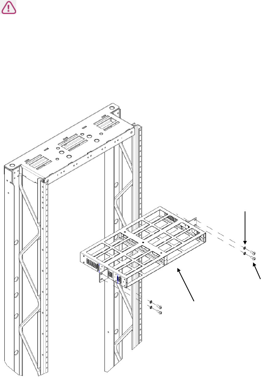
STEP 1: Install the 1U rack mount kit on the rack using 4 M6 screws and 4 lock washers. Tighten the screws to 4.8
Newton meters of torque.
M6 Pan head
screws
1U Rack
mounting shelf
M6 toothed
lock washers
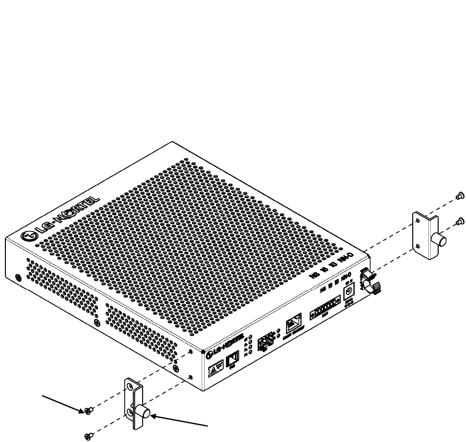
STEP 2: Unfasten the M3 pan head screws from each side of the NS 16 1G NN-O (see following illustration). Tighten
the screws to 1 Newton meter of torque.
STEP 3: Attach the set back brackets using the screws that were removed in STEP 2.
M3x6MHEAD
CREWS
x6MM FLAT
Mounting method (continued)
M3 x 6mm FLAT
HEAD SCREWS
SETBACK BRACKET
HEAD SCREWS
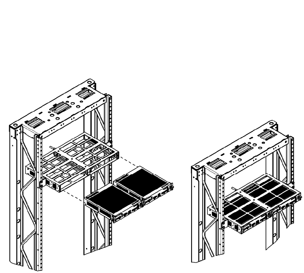
STEP 4: Insert the EABU into the rack mount and tighten the M3 captive fasteners on the setback bracket in order to
secure it to the rack mount.
Mounting method (continued)
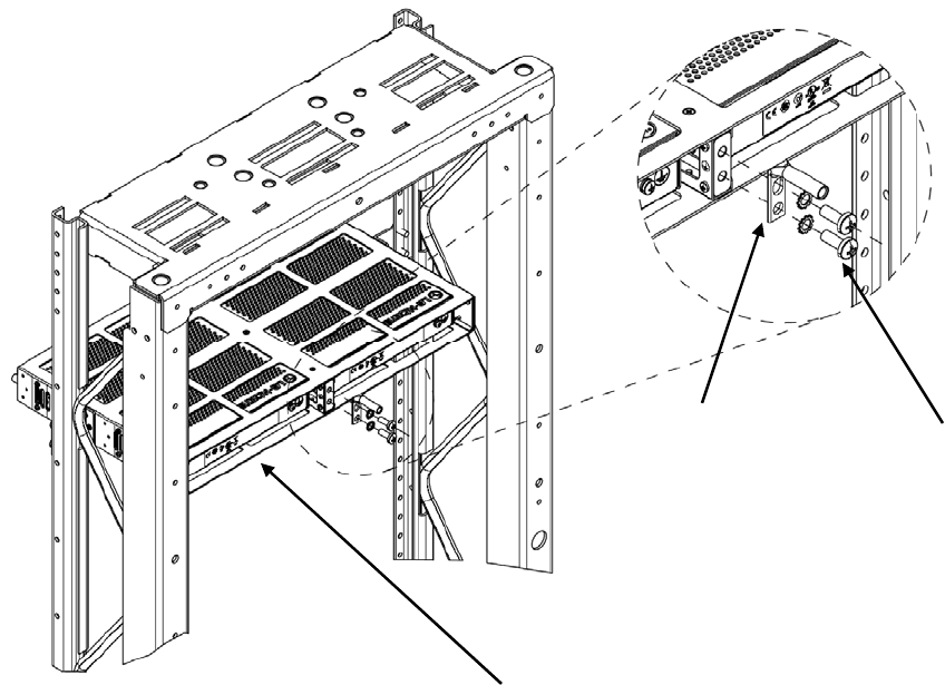
Grounding
STEP 1: Unfasten the grounding screws on the rear side of the 1U Rack mounting shelf (see following illustration).
STEP 2: Attach the 2-hole lug using the screws that was removed in STEP 2. Tighten the screws to 4.8 Newton meters
of torque.
A 2-hole #10 compression with 6.6mm(0.26inch) hole spacing is acceptable for the NS 16 1G NN-O.
The grounding connection is suitable for terminating a #6 AWG wire.
1U Rack
mounting shelf
2-hole lug Grounding
screws
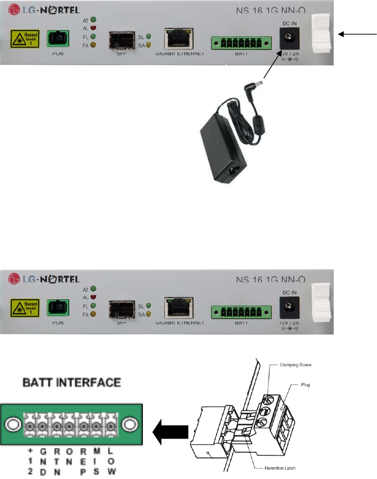
Connecting power cable
For AC/DC adaptor connection
Lift up the cable retaining clip and connect the AC power cable.
Pull down the cable retaining clip to lock in the power cable.
The AC power cable must comply with “IEC60320 C14”
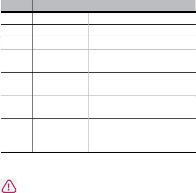
For Battery connection
Connect the Battery plug to BATT interface.
AC/DC power adaptor
Cable retaining clip
CAUTION
Do not pull on the power cable. This can cause failure or damage to the NS 16 1G NN-O.
Mark Signal Name Description
+12V + Voltage + Voltage
GND - Voltage - Voltage
RTN Signal Return Signal Return
ON On Battery Low when operating from utility line.
Open when operating from battery.
REP Replace Battery Low when battery is charged. Open
when battery fails the Self Test.
MIS Battery Missing Low when battery is present. Open
when battery is missing.
LOW Low Battery
Low when battery is near full charge
capacity. Open when operating from a
battery with < 20% capacity.
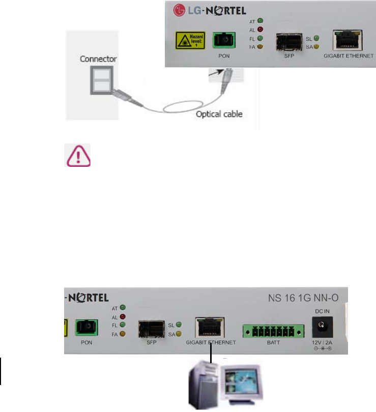
Connecting optical cable
Check that the power switch on the NS 16 1G NN-O is in the off position. Insert the SC APC connector into the optical
port of the NS 16 1G NN-O. Insert the other end of the APC optical cable into the optical outlet on your wall.
CAUTION
Only SC APC connector should be used. Other connector types will not work properly.
Connecting Ethernet cable
Connect Ethernet cables to the RJ45 Ethernet port numbered 1 to 4 in NS 16 1G NN-O.
Connect the other side of the Ethernet cable to the Ethernet port of your home device.
SC APC
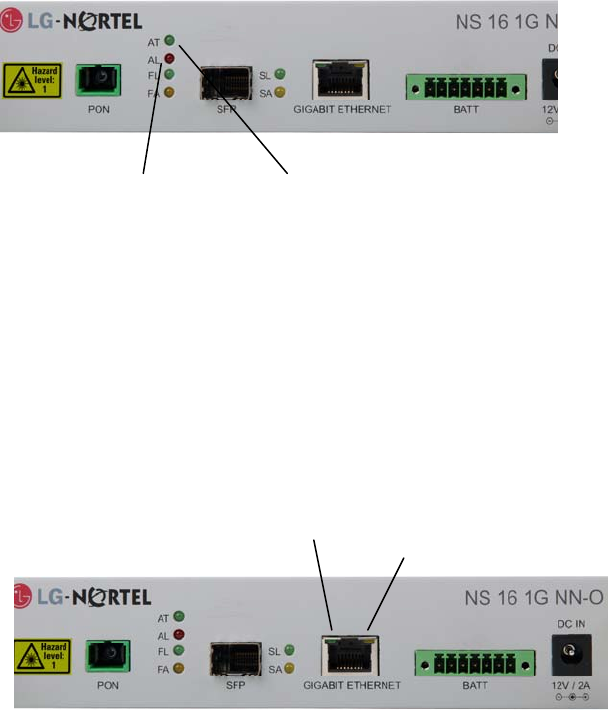
Checking the connection status
Checking the connection status of service provider line (Link)
When the NS 16 1G NN-O is first powered on, the AL LED should turn red
momentarily. Once communication is
established this LED turns off. The AT LED should turn green and blink.
Checking the connection status of user devices
When NS 16 1G NN-O is power-fed, the Green and Orange LEDs should be on.
The green LED is the data indicator. It blinks when data is being transmitted or
received. The orange LED is the link indicator. It lights up with a 100Mbps
connection. If there is a 10Mbps connection (a 10BaseT connection), the orange
LED is off.
AL LED AT LED
Green Orange
Setting NS 16 1G NN-O
When you select to receive WDM-PON service, you do not have to make additional
settings on the product to use it.
Using Internet
With a web browser such as the Internet Explorer on your PC, you can surf freely
through the Internet.
Note
NS 16 1G NN-O does not require any access program.
Use your regular internet browser.