Ericsson LG WIT400HE Wireless IP Terminal User Manual
Ericsson-LG Co., Ltd. Wireless IP Terminal
User Manual
WIT-400HE
Installation Manual
THIS DOCUMENT CONTAINS PROPRIETARY INFORMATION
AND MAY NOT BE REPRODUCED OR COPIED WITHOUT
EXPRESS WRITTEN PERMISSION OF A DULY
A
UTHORIZED
REPRESENTATIVE OF LG-Ericsson Co.Ltd.
Mar. 15-2012
WIT-400HE Installation Manual
Date: 15/M ar/2012
This Document Contains proprietary information and may not be reproduced or copied without express
Written permission of a duly authorized representative of Ericsson-LG Co.Ltd.
2
REVISION HISTORY
ISSUE DATE BY REMARK
0.9A Mar. 15 2012 Wireless Part Preliminary Release
0.9A Mar. 20.2012 Jongmin Choi Update s/w upgrade process and system registration.

WIT-400HE Installation Manual
Date: 15/M ar/2012
This Document Contains proprietary information and may not be reproduced or copied without express
Written permission of a duly authorized representative of Ericsson-LG Co.Ltd.
3
TABLE OF CONTENTS
SAFETY INSTRUCTIONS .................................................................................... 6
SAFETY INFORMATION .................................................................................... 6
1. GETTING STARTED ................................................................................... 7
1.1 OPTIONS & BASIC ENCLOSURE ..................................................................................................... 7
1.2 WIRELESS NETWORK CELL .......... ... .... .... .... .... .... ... .... .... .... .... .... .... ... .... .... .... .... .... ... .... .... .... .... .... .. 8
1.3 ACCESS POINT ................................................................................................................................ 9
1.3.1 WHICH ONE IS BETTER ......................................................................................................... 10
1.3.2 HOW TO SET UP MULTIPLE APS ........................................................................................... 11
1.3.3 RECOMMENDED AP SPECIFICATION FOR WIT-400HE ........................................................ 11
1.4 IPECS SYSTEM ............................................................................................................................. 12
2. WIRELESS ENVIRONMENT SETUP ..................................................... 12
2.1 BASIC IEEE 802.11B/G NETWORK DIAGRAM ............................................................................. 12
2.2 WHERE IPECS SYSTEM IS POSITIONED IN THE 802.11B/G NETWORK. ............................. ........ 12
2.3 AP CONFIGURATION ..................................................................................................................... 13
2.3.1 SSID ...... ........ ....... ........ ........ ....... ........ ........ ....... ........ ........ ....... ........ ........ ....... ........ ............ 13
2.3.2 DTIM (DATA TRAFFIC INDICATION MAP) & BEACON ........................................................ 13
2.3.3 CONFIGURATION .................................................................................................................. 14
3. S/W UPGRADE ........................................................................................... 15
3.1 NETWORK CONFIGURATION FOR UPGRADE ............................... ....................... ........................... 15
3.2 WEB SERVER SETTINGS .......... ........................... ........................... ........................... ................... 15
3.3 USB ENABLE ........................................................... 오류! 책갈피가 정의되어 있지 않습니다.
3.4 STARTING UPGRADE ........................ ............ ............ ........... ............ ........... ............ ........... ............ 16
4. DEBUG DATA TRANSFER AND DIAG DATA TRANSFER .............. 20
4.1 DEBUG DATA TRANSFER .......................................................................................................... 20
4.1.1 CHECK DEBUG SETTING ...................................................................................................... 20
4.1.2 SENDING DEBUG DATA FROM WIT-400HE ............... .... .... .... ... .... .... .... .... .... .... ... .... .... .... .... 20
4.2 STARTING DIAG. SERVER OF WIT-400HE ................ ....................... ....................... .................... 21
4.2.1 CHECK DIAG SETTING ......................................................................................................... 21
4.2.2 SENDING DIAG. DATA FROM WIT-400HE .. ........... ............ ........... ................ ........... ............ 22
4.2.3 GETTING DIAG. DATA ON THE PC ....................................................................................... 22
4.2.4 DIAG. SAMPLE DATA ........................................................................................................... 23
5. CELL PLANNING ...................................................................................... 25
5.1 ACCESS POINT REQUIREMENTS .................................................................................................. 25
5.2 ACCESS POINT RANGE ................................................................................................................. 25
5.3 ACCESS POINT POSITIONING ....................................................................................................... 25
5.4 RSSI MONITORING ....................................................................................................................... 29

WIT-400HE Installation Manual
Date: 15/M ar/2012
This Document Contains proprietary information and may not be reproduced or copied without express
Written permission of a duly authorized representative of Ericsson-LG Co.Ltd.
4
5.5 HANDOVER .................................................................................................................................... 30
5.6 TUNING POINTS ............................................................................................................................. 31
6. IPECS LIK SETUP ..................................................................................... 33
6.1 MFIM S/W VERSION ..................................................................................................................... 33
6.2 WIT-400HE REGISTRATION ..................................................................................................... 33
6.2.1 MFIM SETTING .................................................................................................................... 33
6.2.2 PROFILE SETTING OF WIT-400HE ....................................................................................... 34
6.2.3 SYSTEM SETTING OF WIT-400HE ....................................................................................... 35
6.2.4 TROUBLE SHOOTING FOR REGISTERING FAULT .................................................................. 35
7. IPECS CM SETUP ...................................................................................... 37
7.1 MFIM S/W VERSION ..................................................................................................................... 37

WIT-400HE Installation Manual
Date: 15/M ar/2012
This Document Contains proprietary information and may not be reproduced or copied without express
Written permission of a duly authorized representative of Ericsson-LG Co.Ltd.
5
PREFACE
The main objective of this document is to provide an instruction for proper installation of WIT-400HE.
Mechanical feature is simply described and operation condition is precisely addressed to prevent the
WIT-400HE from malfunctioning by environmental reason. In advance of the environmental consideration,
please refer to this document it will help an installer in setting up basic circumstance for normal operation
of the WIT-400HE.

WIT-400HE Installation Manual
Date: 15/M ar/2012
This Document Contains proprietary information and may not be reproduced or copied without express
Written permission of a duly authorized representative of Ericsson-LG Co.Ltd.
6
Safety Instructions
WARNING! To reduce the possibility of electric shock, do not expose your phone to high humidity areas,
such as the bathroom, swimming pool, etc.
Always store your phone away from heat. Never store your phone in settings that may expose it to
temperatures less than 32°F or greater than 104°F, such as outside during a snow storm or in your car on
a hot day. Exposure to excessive cold or heat will result in malfunction, damage and/or catastrophic
failure.
Be careful when using your phone near other electronic devices. RF emissions from your mobile
phone may affect inadequately shielded electronic equipment nearby. You should consult with
manufacturers of any personal medical devices, such as pacemakers and hearing aides, to determine if
they are susceptible to interference from your mobile phone. Turn off your phone in a medical facility or at
a gas station. Never place your phone in a microwave oven as this will cause the battery to explode.
IMPORTANT! Please read the IEC SAFETY INFORMATION before using your phone.
Safety Information
Please read and observe the following information for the safe and proper use of your phone and to
prevent any unanticipated damage by accident. Also, keep the user’s manual in an accessible place at all
times after reading it.
Unplug the power cord and charger during a lightning storm to avoid electric shock or fire.
Do not use your phone in high explosive areas, as the phone may influence high frequency devices.
Do not put your phone in a place subject to excessive dust, and be careful to keep the minimum
required distance between the power cord and heat sources.
Unplug the power cord prior to cleaning your phone, and clean the power plug pin when it is dirty.
Do not damage the power cord by bending, twisting, pulling, or heating. Do not use the plug if it is
loose, as it may cause fire or electric shock.
Hold the power cord plug firmly to plug and unplug the power cord. Ensure the plug is firmly
connected. If it is not firmly connected, it may cause excessive heat or fire.
Do not place any heavy item on the power cord. Do not allow the power cord to be crimped, as it may
cause fire or electric shock.
Be careful not to let the battery contacts touch metal conductors such as a necklace or coins. When
shorted, it may cause an explosion.
Do not disassemble or allow heavy impact to the battery as it may cause electric shock, short-circuit,
and fire. Store the battery in a place out of reach of children.
Using a damaged battery or placing a battery in your mouth, may cause serious injury.
Do not place items with a magnetic strip, such as a credit card, phone card, bank book and a subway
ticket, near your phone. The magnetism of the phone may damage the data stored in the magnetic
strip.
Do not hold or let the antenna come in contact with your body during a call.
Talking on your phone for a long period of time may reduce the call quality due to heat generated
during use.
Do not allow excessive vibration or impact to the phone.
When you do not use the phone for a long period time, store it in a safe area with the power cord
unplugged.
WIT-400HE Installation Manual
Date: 15/M ar/2012
This Document Contains proprietary information and may not be reproduced or copied without express
Written permission of a duly authorized representative of Ericsson-LG Co.Ltd.
7
1. Getting Started
1.1 Options & Basic Enclosure
Cautions
Using the phone near receiving equipment (i.e., TV or radio) may cause interference.
Keep your phone in a safe place when not in use.
Only use the batteries, antennas, and chargers provided by LG-Ericsson. Using unauthorized
accessories could void your warranty.
Only authorized personnel should service the phone and its accessories. Faulty installation or service
may result in accidents and consequently void the warranty.
Do not hold the antenna while the phone is in use.
Do not use the phone in designated no cellular phone use areas.
Do not expose the phone to high temperature or humidity.
Avoid getting your phone wet. If the phone gets wet, turn the power off immediately and remove the
battery. If the phone is non-functional, return it to the dealer for service.
Avoid shock or impact to the phone.
Basic Enclosures:
Unpacking the box, customer will see the following items.
1) WIT-400HE Phone
WIT-400HE WiFi Phone. You should
be able to find MAC address tag at
the back side of the phone.
2) Rechargeable battery
Rechargeable battery. LG-Ericsson
logo should be displayed.
3) Travel adaptor/
Power cable
The one end is plugged into power
tab, the other one is slotted into WIT-
400HE Jack.
4) Handstrap
5) Ear Microphone
In the cable of ear-microphone, there
is a remote control button. It is useful
for hands-free way operation.
This Do
c
Written
p
6) Use
r
7) Des
k
8) Unit
Option
s
U
1) USB
If you fi
n
LG-Eric
s
1.2
Fundam
of more
c
ument Cont
a
p
ermission o
f
r
manual
k
top Holder
Label
s
:
ser need to
B
cable
n
d the trade
m
s
son Co.Ltd.
Wireless
ental topolo
g
than two cel
WIT-400
H
a
ins proprieta
r
f
a dul
y
autho
r
purchase d
e
m
ark of LG-
E
Network
C
g
y of the IE
E
l ranges. Th
e
H
E Installati
o
ry
in
f
ormati
o
r
ized represe
n
e
sktop holde
r
E
ricsson on
t
C
ell
E
E 802.11b/
g
e
following fi
o
n Manual
o
n and ma
y
n
o
n
tative o
f
E
ri
c
8
r
with additi
o
t
he recharg
e
g
based wir
e
gure shows
o
t be reprodu
c
c
sson-LG Co
.
h
D
D
o
nal paymen
t
e
able batter
y
e
less networ
k
the exampl
e
c
ed or copie
d
.
Ltd.
h
ttp://www.lg
e
D
ownload >
M
D
esktop hold
t
.
y
, the delive
r
k
ing is the o
v
e
of a cell ar
e
Date: 15
d
without exp
r
e
ricsson.co
m
M
anual-MP
R
er will be pr
o
r
y is strictly
c
v
erlapped c
o
e
a.
/M ar/2012
r
ess
m
/ >
R
o
vided.
c
onfirmed b
y
o
ncatenatio
n
y
n
WIT-400HE Installation Manual
Date: 15/M ar/2012
This Document Contains proprietary information and may not be reproduced or copied without express
Written permission of a duly authorized representative of Ericsson-LG Co.Ltd.
9
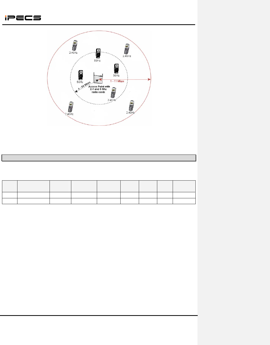
The WIT-400HE is only 802.11b/g compliant, its maximum frequency is 2.4GHz and 54 Mbps maximum
bandwidth. For more detail information of cell planning, please refer to the manual of AP.
1.3 Access Point
The following is a list of APs that have been made an imperative experimentation with the WIT-400HE
and the result.
Rank AP Max retry
counter
Simultaneous
Call
Reject after
Full Assoc Roaming Multiple
SSID
Power
control WPA
Best Cisco – AP1231G O 12 X O O O O
Good Cisco
–
AP1121G O 10 X O O O O
Max retry counter : It’s the maximum retry counter of data packet from AP to client. If the retry counter
of a packet exceeds the limit, the packet is discarded. If the AP don’t support max retry counter, it can
make network busy by excessive retransmit when a user goes to out-of-range in conversation.
When the receiving packet rate is very low during 10 seconds, WIT-400HE disconnects the call to prevent
excessive retransmit of packets.
The simultaneous calls are estimated in idle network configuration, so it can be decreased by the
network condition. When the AP is commonly used for data and voice, the bandwidth for voice call will be
decreased. If you use overlapping channels, radio frequency interference can occur, which leads to
connectivity issues and in poor throughput.
Reject after Full Assoc. : This feature support to restrict the number of association simultaneously for
load balancing.
Roaming : It means that the call in conversation is not disconnected when it reams to other AP. To
support seamless roaming, the signal range of each AP should be overlapped.
If you need to use roaming feature, we strongly recommend Cisco AP. The other APs above support
roaming but they are unstable. We received report that the phone is muted sometimes after roaming with

WIT-400HE Installation Manual
Date: 15/M ar/2012
This Document Contains proprietary information and may not be reproduced or copied without express
Written permission of a duly authorized representative of Ericsson-LG Co.Ltd.
10
Linksys AP. We found that sometime the AP doesn’t send packets after roaming in our laboratory
investigation.
O : We strongly recommend.
∆: It supports roaming feature, but it’s unstable or not verified enough.
X : It doesn’t support roaming feature.
Multiple SSID : The AP supports multiple SSID.
AP TX Power Control : It can control the signal range of AP. It’s very important to install multiple APs in
small area. The frequency of adjacent APs is overlapped too much, you can decrease the transmit power
to reduce the interference of radio frequency.
WPA : It make wireless network more securely protected. It authenticates with the server and changes
the encryption key dynamically.
IPOne AP is made in Korea.
Note: In case using AP supported 802.11n, we recommend Cisco Aironet 1250 Series AP. However, you
must reconsider cell plan include because of the characteristics of 802.11n MIMO AP. We recommend
you contact the Access Point technical support team
1.3.1 Which one is better
Depending on the internal implementation of IEEE802.11b/g protocol inside of the APs, roaming across
two contiguous regions may be affected. Cisco is currently showing most optimized seamless roaming.
CISCO APs are strongly recommended to customers. IPOne is estimated that it’s less than CISCO
but it performed good as we can recommend. Other APs did work well in low traffic, but it’s
unstable in high voice traffic, more than 8 calls simultaneously. Other APs also don’t support
transmit power control.
If you need to use multiple APs, we strongly recommend Cisco AP. The other APs are unstable for the
roaming feature.
The most important thing to select AP is the environment of the site to install. The number of
simultaneous voice call should be considered carefully to support stable voice quality. We also
recommend that the association number of an AP doesn’t exceed 30 clients to prevent poor voice quality.
We can suggest as follows in each conditions.
(1) 20 ~ 30 clients in an AP (less than 12 calls simultaneously)
A. Cisco-AP1231G
(2) 10 ~ 20 clients in an AP (less than 10 calls simultaneously)
A. Cisco-AP1231G
B. Cisco-AP1121G
(3) Less than 10 clients in an AP (less than 8 calls simultaneously)
A. Cisco-AP1121G
WIT-400HE Installation Manual
Date: 15/M ar/2012
This Document Contains proprietary information and may not be reproduced or copied without express
Written permission of a duly authorized representative of Ericsson-LG Co.Ltd.
11
1.3.2 How to set up multiple APs
Our recommendation is that one AP(Access Point) is used for one cell area. If you would install
more than two APs for a cell, we recommend you to use the same SSID for each AP. And the APs
should have different RF channel far away than 5 channels each other. For example, AP1 has RF
channel 1, then AP2 should have RF channel 6. If the RF channel number of the APs is overlapped
near within 5 channels, the retransmission for data communication may be increased. As the
result of this the standby time of WIT-400HE may be decreased and the voice quality will be very
poor. So, you should check this carefully.
If you want to increase the capacity of wireless network by increasing APs, you need to control
the transmit power level of APs not to overlap too much. If the radio frequency is overlapped too
much, it can decrease the throughput of the APs.
Please refer to “6. Cell Planning” chapter to get the detail information for installing multiple APs
1.3.3 Recommended AP specification for WIT-400HE
There are many kinds of Access Point in the world. To recommend proper Access Point for WIT-400HE,
LG-Ericsson specified as the following. An Access point has more satisfied item, it is better to WIT-400HE.
When you purchase an AP, you’d better to refer to this list.
No Item Description
1 802.11 b/g 802.11 b/g should be supported
2 Simultaneous call Minimum 4 simultaneous calls should be supported
3 Reject access when full traffic It can be adjusted in the admin program
4 Max retry counter It can be set in the admin program or should not be
transmitted
5 Continuous call Long term call(longer 12 hours) should be supported
6 Roaming within same kind of AP Seamless handover/roaming should be supported
7 Traffic distance Longer than 200 meters
8 Antenna diversity More than 2 antennas
9 AP manager AP manager can some configuration like channel, SSID,
WEP key, and so on.
10 WDS Wireless Distribution System should be supported
11 External antenna Connector type should be supported
12 European CE Type Approval CE should be approved for European market
13 USA UL Type Approval UL should be approved for USA market
14 USA FCC Type Approval FCC should be approved for USA market
15 Canada CSA Type Approval CSA should be approved for Canada market
16 Korea MIC Type Approval MIC should be approved for Korea market
17 WiFi certification WiFi should be certified for mutual compatibility
18 RF power control Fixed power and auto power should be supported
19 DHCP, NAT DHCP and NAT should be supported
20 Price Low price
21 QoS Voice packet should be handled with high priority
WIT-400HE Installation Manual
Date: 15/M ar/2012
This Document Contains proprietary information and may not be reproduced or copied without express
Written permission of a duly authorized representative of Ericsson-LG Co.Ltd.
12
1.4 iPECS System
The iPECS System is a call controller of the WIT-400HE. WIT-400HE can be registered within a same
LAN subnet or other subnet which is routed to the system network.
2. Wireless Environment Setup
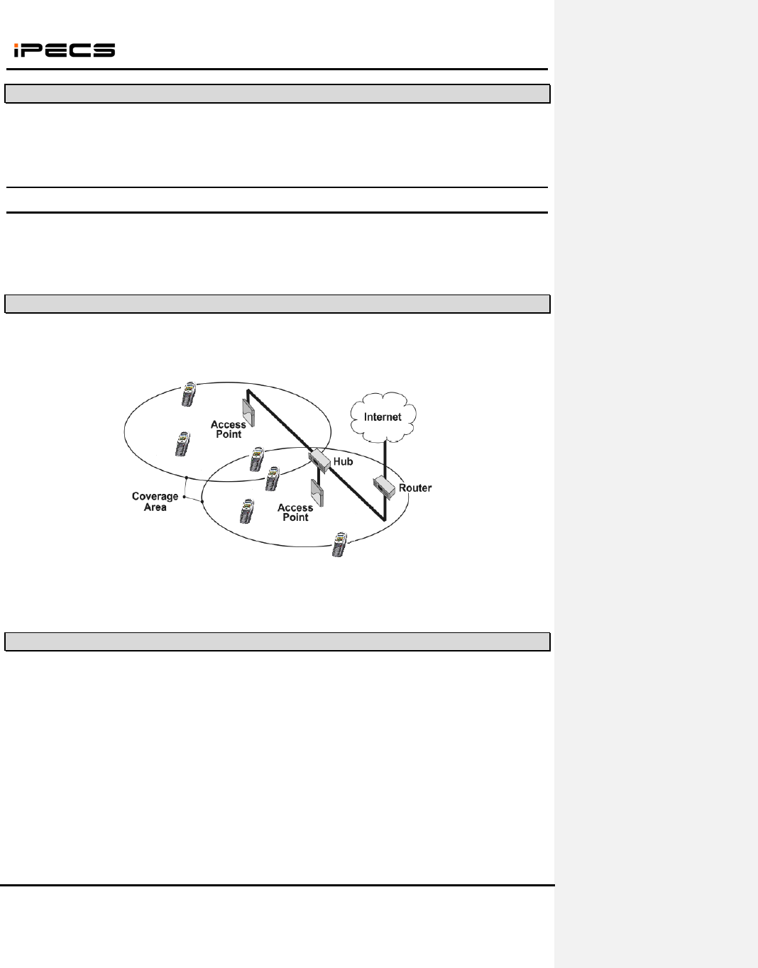
This section describes AP(Access Point) configuration for normal operation of WIT-400HE. The AP
should be plugged into a switch/hub for connectivity with the subnet of office.
2.1 Basic IEEE 802.11b/g network diagram
The following figure exhibits network infrastructure of 802.11b/g compliant network diagram.
APs are connected to a HUB in subnet, since WIT-400HE is able to access the Internet. The iPECS LIK
and WIT-400HE system work on top of this context.
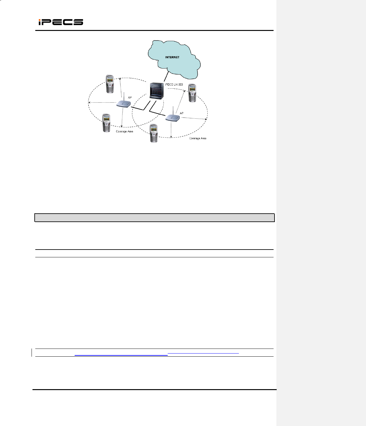
2.2 Where iPECS System is positioned in the 802.11b/g network.
The following is a basic configuration of IEEE802.11b/g environment to enable WIT-400HE and the
iPECS System.
WIT-400HE Installation Manual
Date: 15/M ar/2012
This Document Contains proprietary information and may not be reproduced or copied without express
Written permission of a duly authorized representative of Ericsson-LG Co.Ltd.
13
(1) WIT-400HE / AP:
- IEEE 802.11b/g network
- SSID / DTIM interval configuration within AP
(2) AP / iPECS LIK:
- Direct connection : AP PoE of iPECS System
- Indirect connection : AP HUB PoE of iPECS System
2.3 AP Configuration
Depending on vendors of AP, the following two parameters should be carefully set up.
2.3.1 SSID
SSID is for authentication use. An AP can have an arbitrary SSID value for example “wireless”. In this
case, WIT-400HE with “wireless” SSID can communicate with that AP. It is important to use accurate
SSID on both WIT-400HE and AP.
Recommendation)
(1) If you are free of security, please just use one SSID for all APs and WIT-400HE.
(2) If you are using WIT-400HE in a wireless environment with predetermined SSID, please
change the SSID of your WIT-400HE.
2.3.2 DTIM (Delivery Traffic Indication MessageData Traffic Indication Map) & Beacon
DTIM is related to an interval of packet transmission. By an inherent nature of the iPECS LIK, WIT-400HE
frequently uses multicast message for the communication with the iPECS LIK. The delivery of multicast
WIT-400HE Installation Manual
Date: 15/M ar/2012
This Document Contains proprietary information and may not be reproduced or copied without express
Written permission of a duly authorized representative of Ericsson-LG Co.Ltd.
14
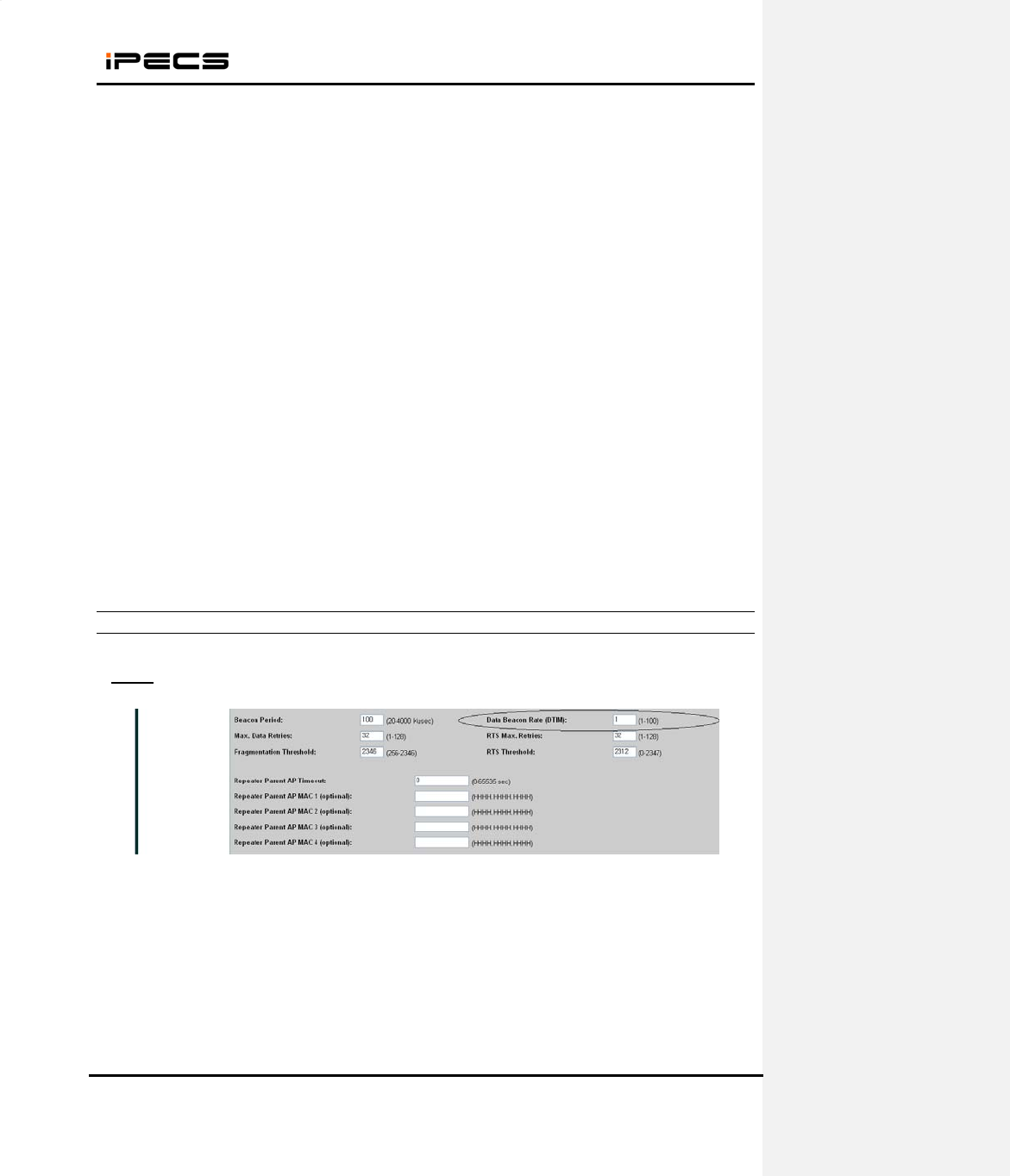
message is affected by the DTIM parameter.
Beacon is an indication of packets buffered in AP which are to be delivered to each wireless station, WIT-
400HE. The information of DTIM is contained in a beacon message. Therefore, DTIM configuration can
be affected by the beacon interval. The following is illustrating the relationship of beacon and DTIM:
Recommendation)
(1) DTIM should be less than 200 msec.
(2) If AP doesn’t support DTIM configuration, more special care needs to be taken for Beacon
interval setup. Otherwise, Use the smallest DTIM interval that AP can support.
2.3.3 Configuration
This section enumerates how you set up both SSID and DTIM in AP.
Cisco
(1) Open a page “Network Interfaces > Settings” . You can see a edit box “DTIM”.
(2) Enter 3.
WIT-400HE
WIT-400HE Installation Manual
Date: 15/M ar/2012
This Document Contains proprietary information and may not be reproduced or copied without express
Written permission of a duly authorized representative of Ericsson-LG Co.Ltd.
15
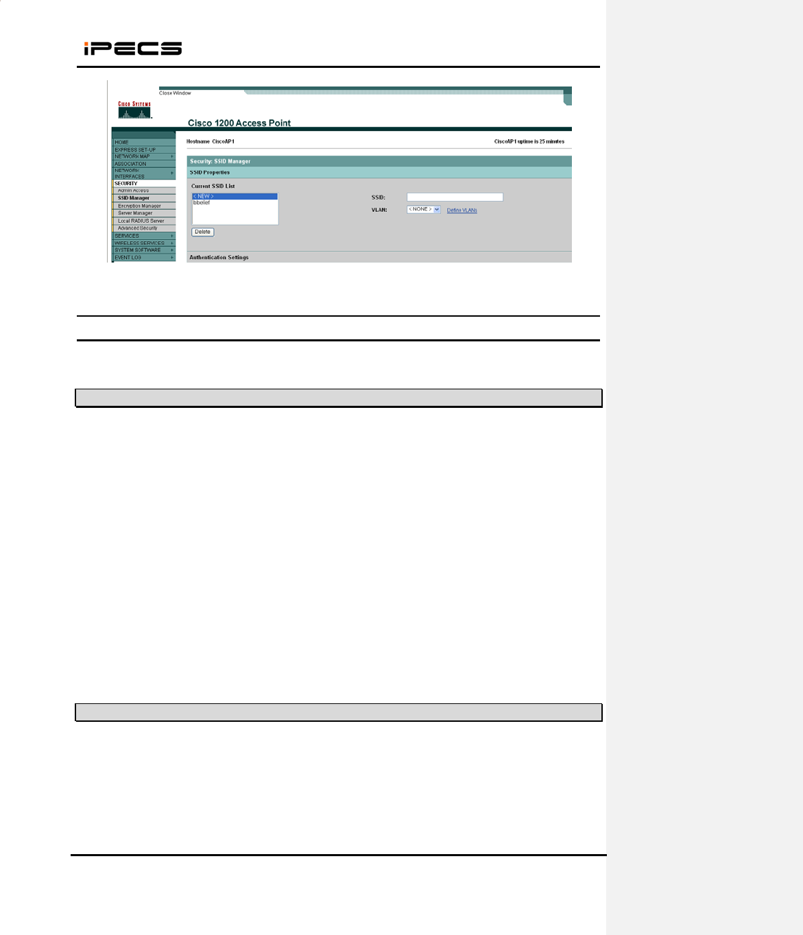
(3) Open a page “Security > SSID Manager” . You can see a edit box “SSID”.
(4) Enter your SSID.
3. S/W Upgrade
WIT-400HE can be upgraded via USB or WLAN.
3.1 Network configuration for upgrade
3.2 WEB Server Settings
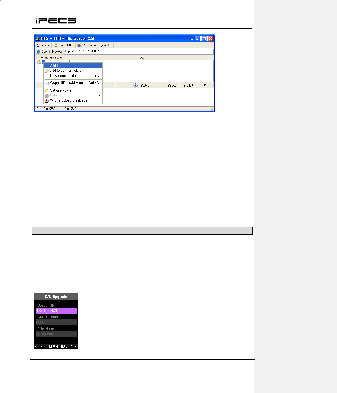
1. Create “C:\WIT400H” directory and copy HTTP File Server (hts.exe) to the directory
2. Run hfs.exe
3. Add file to upgrade
1. Connect PC LAN port to the network.
2. Connect WIT-400HE to wireless network.
WIT-400HE Installation Manual
Date: 15/M ar/2012
This Document Contains proprietary information and may not be reproduced or copied without express
Written permission of a duly authorized representative of Ericsson-LG Co.Ltd.
16
4. New image file is added
3.3 Starting Upgrade
1. When WIT-400HE is boot up completely, connect USB cable or WLAN network.
2. Press “*1475963#” + “Send” button.
3. Select “3. S/W Upgrade” and set the server IP, port and file name.
Server Port #
S/W image file
WIT-400HE Installation Manual
Date: 15/M ar/2012
This Document Contains proprietary information and may not be reproduced or copied without express
Written permission of a duly authorized representative of Ericsson-LG Co.Ltd.
17
1) Server IP: IP address of Web Server
2) Server Port: Web Server Port#
3) File Name: New S/W image of WIT-400HE
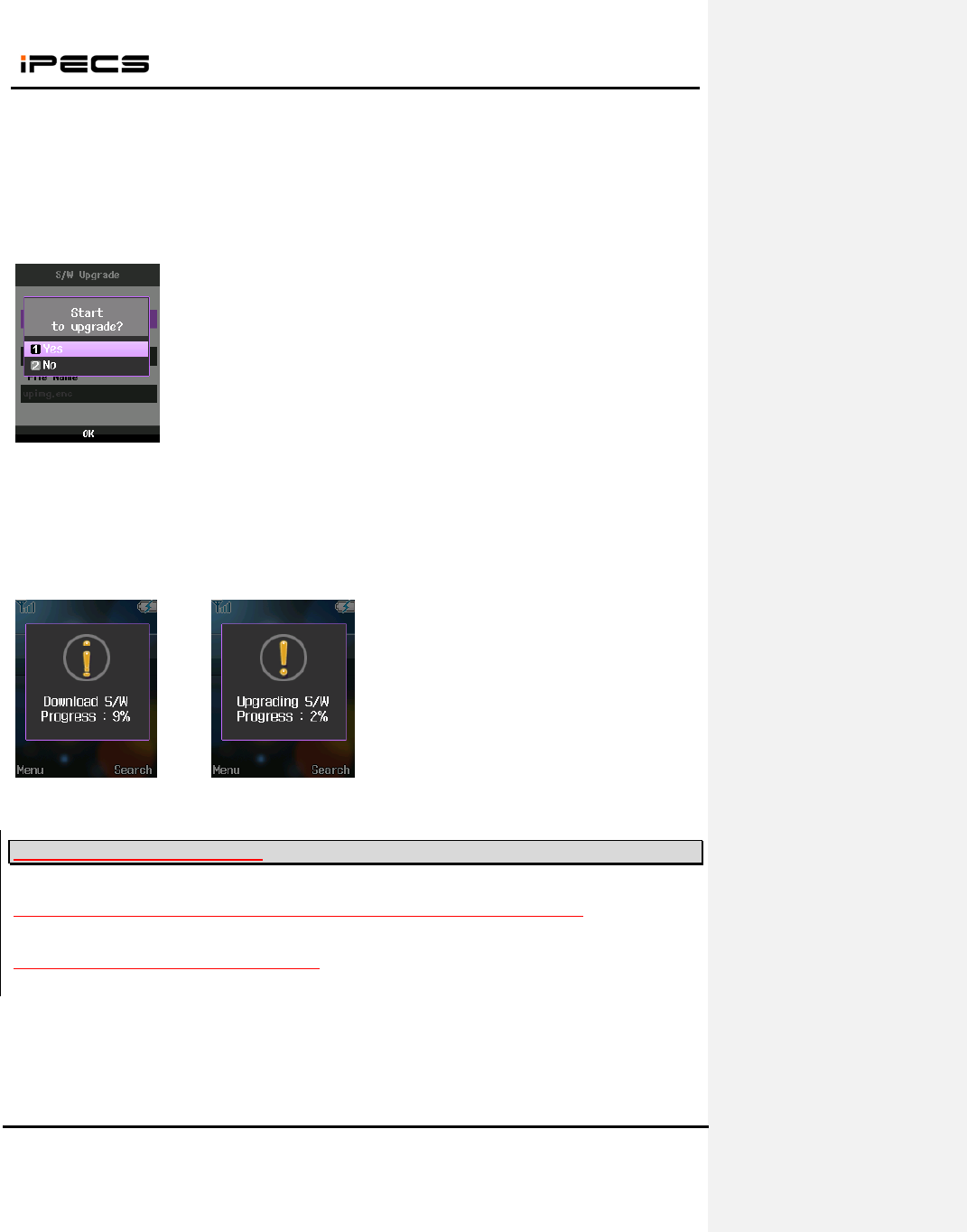
4. When you select “DOWN LOAD”, popup will be displayed. Press “YES” to start upgrade.
5. The process has three steps as follows.
1) 1st step : S/W download
2) 2nd step : apply new S/W to the flash
3) 3rd step : reboot after upgrade
<Download> <Upgrade>
3.4 S/W Upgrading via MFIM
WIT-400HE could be updated on MFIM web admin same as IP Phone upgrade process.
1. Open File Upload menu in MFIM web admin.
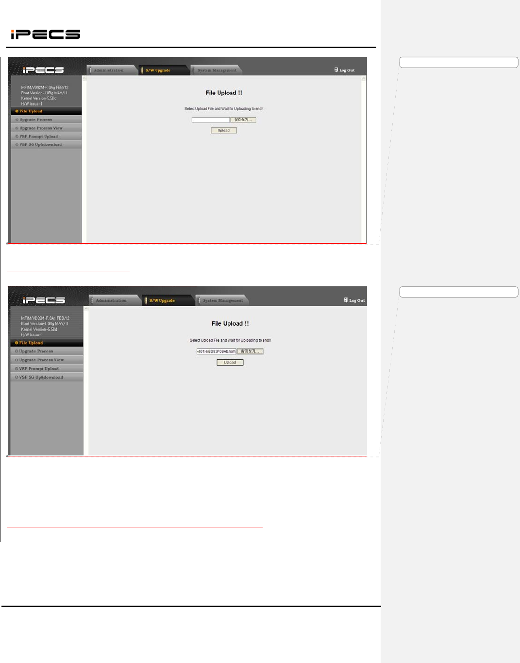
WIT-400HE Installation Manual
Date: 15/M ar/2012
This Document Contains proprietary information and may not be reproduced or copied without express
Written permission of a duly authorized representative of Ericsson-LG Co.Ltd.
18
2. Upload WIT-400HE f/w to MFIM.
The f/w image of WIT-400HE is like GS93PXXXX.rom.
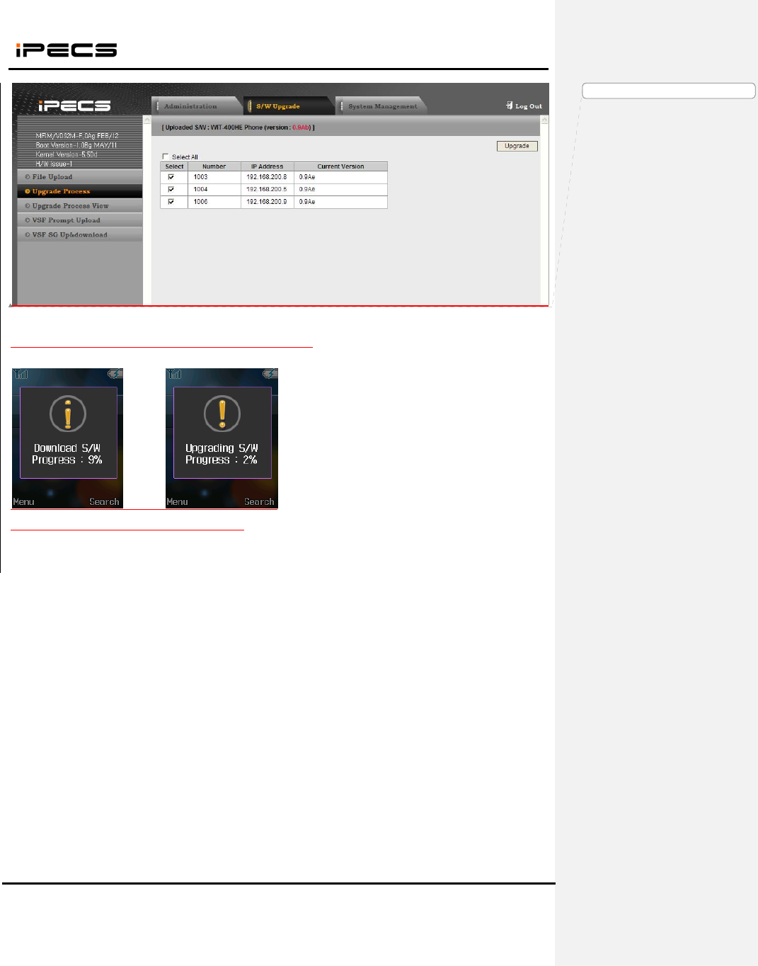
3. Select extension number to upgrade and press upgrade button to start.
서식 있음: 글꼴: (영어) Arial
서식 있음: 글꼴: (영어) Arial
WIT-400HE Installation Manual
Date: 15/M ar/2012
This Document Contains proprietary information and may not be reproduced or copied without express
Written permission of a duly authorized representative of Ericsson-LG Co.Ltd.
19
4. WIT-400HE will start downloading f/w and upgrading s/w.
<Download> <Upgrade>
서식 있음: 글꼴: (영어) Arial
WIT-400HE Installation Manual
Date: 15/M ar/2012
This Document Contains proprietary information and may not be reproduced or copied without express
Written permission of a duly authorized representative of Ericsson-LG Co.Ltd.
20
4. Debug Data Transfer and Diag Data Transfer
4.1 Debug Data Transfer
4.1.1 Check Debug Setting
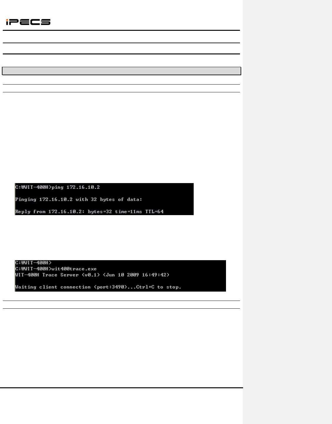
1) Run windows “command prompt”
2) Move to the directory “c:\WIT-400H”, where “wit400trace.exe” exists.
- You can change to any other directory.
3) Try “ping” to the IP address of WIT-400HE.
- If replies, go to next step.
- If not, check the network configuration of PC and WIT-400HE.
4) Run “wit400trace.exe”
- If TCP port 3490 is not available, you can change as “wit400trace.exe [TCP port #]”.
Ex) wit400trace.exe 5000
4.1.2 Sending Debug Data from WIT-400HE
1) Press “*1478621#” + “Send” key
2) Set the level for debugging
- Block Name : each block name
- Mode On/Off: the debug type
- Debug Level : each debug level

WIT-400HE Installation Manual
Date: 15/M ar/2012
This Document Contains proprietary information and may not be reproduced or copied without express
Written permission of a duly authorized representative of Ericsson-LG Co.Ltd.
21
3) Press “OK” to set debug.
4) Press “Send”(Soft Right Menu) to send debug information.
- Server IP : PC IP address which wit400trace.exe is running.
- Server TCP Port : TCP port of the application
5) Press “Send”(OK) to send
- It takes around 20 seconds to get the data.
- If it fails, check the network configuration of PC and WIT-400HE.
- If WLAN of WIT-400HE is not connected, you can use USB cable.
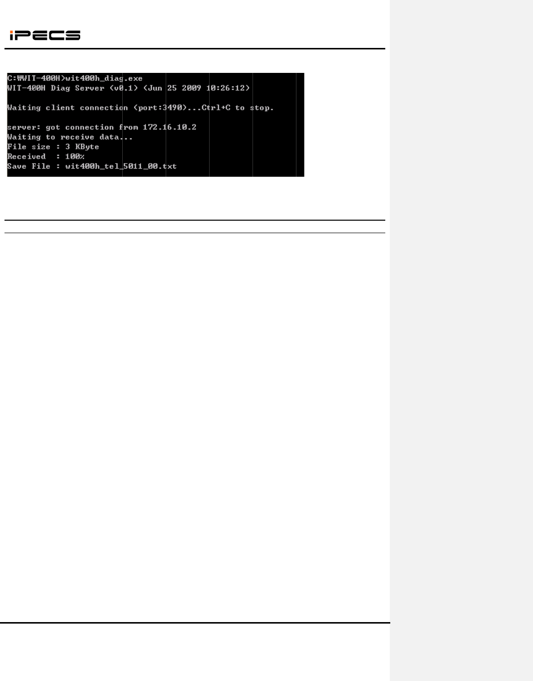
4.2 Starting Diag. Server of WIT-400HE
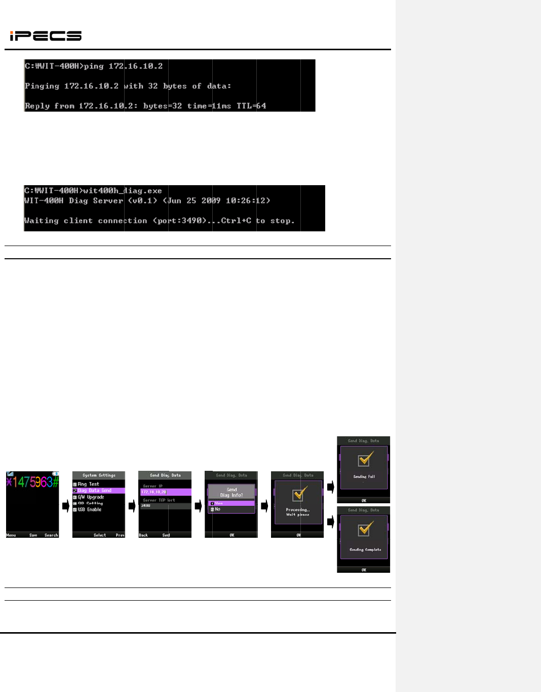
4.2.1 Check Diag Setting
1) Run windows “command prompt”
2) Move to the directory “c:\WIT-400H”, where “wit400h_diag.exe” exists.
- You can change to any other directory.
3) Try “ping” to the IP address of WIT-400HE.
- If replies, go to next step.
- If not, check the network configuration of PC and WIT-400HE.
This Do
c
Written
p
4) Run
“
- If T
C
Ex
4.2.2
1) Pres
s
2) Put t
h
- Se
r
- Se
r
3) Pres
s
- It
t
- If i
- If
W
4.2.3
1) The d
c
ument Cont
a
p
ermission o
f
“
wit400h_di
a
C
P port 349
0
x
) wit400h_di
Sending
D
s
“*1472369
8
h
e PC IP &
P
r
ver IP : PC I
r
ver TCP Po
r
s
“OK” to se
n
t
akes aroun
d
t fails, chec
k
W
LAN of WI
T
Getting
D
d
iag. data wil
WIT-400
H
a
ins proprieta
r
f
a dul
y
autho
r
a
g.exe
”
0
is not avail
ag.exe 500
0
D
iag. Data
8
#” + “Send”
P
ort# on the
m
P address
w
r
t : TCP port
n
d
d
20 second
s
k
the networ
k
T
-400HE is
n
D
iag. Data
o
l be receive
d
H
E Installati
o
ry
in
f
ormati
o
r
ized represe
n
able, you c
a
0
from WIT-
4
ke
y
m
enu
w
hich wit400
h
of the appli
c
s
to get the
d
k
configurati
o
n
ot connect
e
o
n the PC
d
from the p
h
o
n Manual
o
n and ma
y
n
o
n
tative o
f
E
ri
c
22
a
n change a
s
4
00HE
h
_diag.exe i
s
c
ation
d
ata.
o
n of PC an
d
e
d, you can
u
h
one
o
t be reprodu
c
c
sson-LG Co
.
s
“
wit400h_
d
s
running.
d
WIT-400H
E
u
se USB ca
b
c
ed or copie
d
.
Ltd.
d
iag.exe [TC
P
E
.
b
le.
Date: 15
d
without exp
r
P
port #]
”
.
/M ar/2012
r
ess
This Do
c
Written
p
2) You
c
4.2.4
======
=
Dia
g
======
=
<< AP
S
-30 |0
0
-43 |0
A
-43 |0
6
-47 |0
0
<< WL
A
wlan0
<< LAN
wlan0
c
ument Cont
a
p
ermission o
f
c
an get the d
Diag. Sa
m
=
========
=
g
informatio
n
=
========
=
S
CAN LIST
>
0
:11:95:D0:F
A
:0E:DC:2A:
0
6
:0E:DC:2A:
0
0
:0F:66:D8:1
A
N CONNEC
Marvell
8
Mode:M
a
Bit Rate
=
RTS thr:
o
Encrypti
o
Link Sig
n
Rx invali
d
Tx exces
s
CONNECTI
Link enc
a
inet addr
:
UP BRO
A
RX pack
e
TX pack
e
collisions
WIT-400
H
a
ins proprieta
r
f
a dul
y
autho
r
iag. data on
m
ple Data
=
========
=
n
for WIT-40
0
=
========
=
>
>
3:D0|6|WIT-
4
0
F:B2|3|test
|
0
F:B2|3|test|
A:04|6|WIT
4
TION INFO
8
8W8618
E
a
naged Ch
a
=
54 Mb/s
o
ff Fragm
e
o
n key:of
f
n
al level:-32
d
d
nwid:0 R
x
s
ive retries:
0
ON INFO >
>
a
p:Ethernet
:
192.168.13
1
A
DCAST R
U
e
ts:314214
e
e
ts:9082 err
o
:0 txqueuel
e
H
E Installati
o
ry
in
f
ormati
o
r
ized represe
n
the director
y
=
========
=
0
HE (TEL:1
1
=
========
=
400HE|off|0
0
|
on|0531|W
P
on|0531|IE
E
4
00H|on|001
>>
E
SSID:"WIT-
4
a
nnel:6 Ac
c
e
nt thr:off
d
Bm Nois
e
x
invalid cry
p
0
Invalid m
i
>
HWaddr 0
0
1
.119 Bca
s
U
NNING MU
L
e
rrors:0 drop
o
rs:0 droppe
d
e
n:32
o
n Manual
o
n and ma
y
n
o
n
tative o
f
E
ri
c
23
y
which wit4
0
=
=========
=
1
1)
=
=========
=
0
01|NONE|
N
P
A Version 1
E
E 802.11i/
W
1|WPA Vers
4
00HE"
c
ess Point:
0
e
level:-89 d
B
p
t:0 Rx inv
a
i
sc:0 Mis
s
0
:47:5A:11:2
s
t:192.168.1
3
L
TICAST
M
ped:0 overr
u
d
:0 overruns
o
t be reprodu
c
c
sson-LG Co
.
0
0h_diag.ex
e
=
========
=
=
========
=
N
ONE|NON
E
|TKIP | TKI
P
W
PA2 Versio
n
ion 1|TKIP |
0
0:11:95:D0:
B
m
a
lid frag:0
s
ed beacon:
0
2:3A
3
1.255 Ma
s
M
TU:1500
M
u
ns:0 frame:
0
:0 carrier:0
c
ed or copie
d
.
Ltd.
e
is running.
=
========
=
=
========
=
E
|
P
|
n
1|TKIP | C
C
TKIP |
F3:D0
0
s
k:255.255.
2
M
etric:1
0
Date: 15
d
without exp
r
=
==
=
==
C
MP TKIP |
2
55.0
/M ar/2012
r
ess

WIT-400HE Installation Manual
Date: 15/M ar/2012
This Document Contains proprietary information and may not be reproduced or copied without express
Written permission of a duly authorized representative of Ericsson-LG Co.Ltd.
24
RX bytes:27521982 (26.2 MiB) TX bytes:9622734 (9.1 MiB)
Interrupt:10 Base address:0xa000
<< PING TEST RESULT TO SYSTEM >>
PING 192.168.123.100 (192.168.123.100): 56 data bytes
64 bytes from 192.168.123.100: seq=0 ttl=127 time=23.590 ms
64 bytes from 192.168.123.100: seq=1 ttl=127 time=8.909 ms
64 bytes from 192.168.123.100: seq=2 ttl=127 time=5.482 ms
--- 192.168.123.100 ping statistics ---
3 packets transmitted, 3 packets received, 0% packet loss
round-trip min/avg/max = 5.482/12.660/23.590 ms
<< TRACE DATA >>
WIT-400HE Installation Manual
Date: 15/M ar/2012
This Document Contains proprietary information and may not be reproduced or copied without express
Written permission of a duly authorized representative of Ericsson-LG Co.Ltd.
25
5. Cell Planning
5.1 Access Point Requirements
To determine the number of Access Point in a system, you should consider Access Point broadcast range.
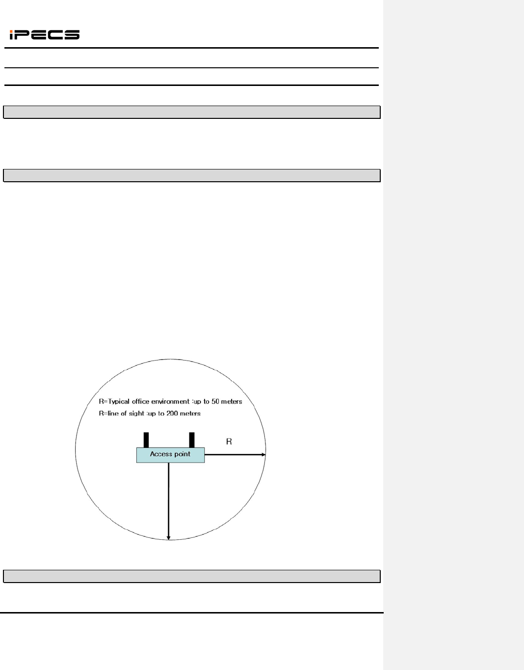
5.2 Access Point Range
In a typical office environment, each Access Point has a broadcast range of 50 meters and supports an
area of 8,000 square meters, but a broadcast range depends entirely upon office environment. Where the
absence of any obstruction provides perfect line of sight conditions between the Access Point and
wireless terminal users and if there are no atmospheric limitations, the range may increase to 200 meters.
If you want to use AP supported 802.11b/g/n mixed mode, this range may decrease to 100 meters
because of the characteristics of AP.
The following Access Point broadcast ranges can be used as a rough guide to plan the Access Point
positions:
z In line of sight, the b/g Access Point has a range of up to 200m(open area).
z In hall, the Access Point has a range of 40-70m.
z In buildings, the Access Point has a range of about 25-40m. It assumes that walls are made of
light brick, plasterboard or wallboard with metal frames. Normal electrical wiring, central heating
pipes, office furniture and desktop computer equipment have no significant effect.
<Figure .1> Access Point Service Area
5.3 Access Point Positioning
The radio coverage area that a single AP provides is not sufficient to serve the entire WLAN in many
WIT-400HE Installation Manual
Date: 15/M ar/2012
This Document Contains proprietary information and may not be reproduced or copied without express
Written permission of a duly authorized representative of Ericsson-LG Co.Ltd.
26
situations. The solution is to increase the radio coverage area.
A. RF channel Specification
The IEEE 802.11 b/g standard establishes several requirements for the RF transmission
characteristics of an 802.11 radio. These channels have a center frequency separation of only 5
MHz and an overall channel bandwidth (or frequency occupation) of 22MHz. So it has
overlapping channels for each channel as shown in figure below. This is true for 802.11b
products running 1, 2, 5.5, or 11 Mbps as well as the newer 802.11g products running up to 54
Mbps.
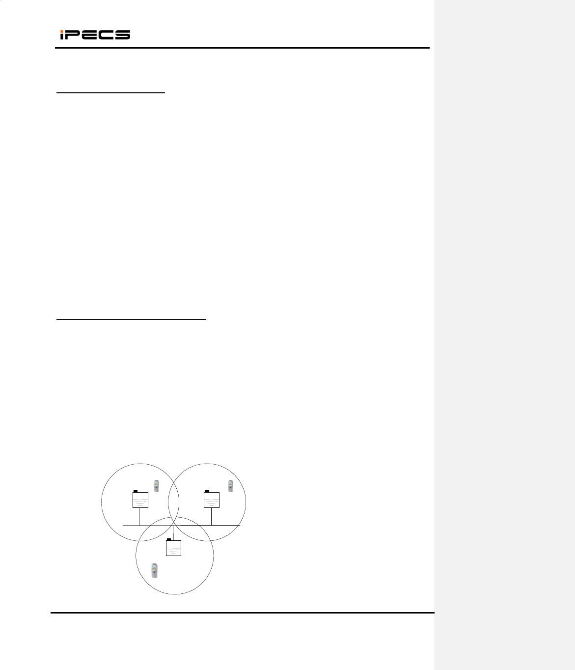
B. Channel Allocation and cell planning
When planning a WLAN cell, you should ensure that the channels that the adjacent APs use are
non-overlapping. Non-overlapping channels are frequency bands that do not have a frequency
that is common to each other. For example in the 2.4GHz range there are three channels that are
non-overlapping (channels 1, 6 and 11). Therefore, when you deploy a secondary AP to extend
the Radio coverage, you can use the channel 1 for the first AP, channel 6 for the next adjacent
AP and channel 11 for the third AP as shown in figure below and then start with channel 1. If you
use overlapping channels, radio frequency interference can occur, which leads to connectivity
issues and in poor throughput. Also, you should ensure that you do not place the APs too close
each other. Too many APs in the same vicinity create radio congestion and RF interference that
can reduce data throughput. A careful site survey can determine the best placement of APs for
maximum radio coverage and optimized throughput.
1 channel 6 channel
11 channel
1 channel 6 channel
11 channel

This Do
c
Written
p
C. QoS
S
d
2
c
ument Cont
a
p
ermission o
f
S
ervice
If you have
a
d
uring the t
e
number of
m
1. QoS Se
r
You cou
2
. QoS Po
l
You cou
WIT-400
H
a
ins proprieta
r
f
a dul
y
autho
r
a
n AP which
e
rminal’s ha
n
m
ute in voice
r
vice
ld select Qo
S
l
icies > Adv
a
ld enable “
Q
H
E Installati
o
ry
in
f
ormati
o
r
ized represe
n
h
could be m
a
n
dover to e
n
during it. A
s
S
service in
a
nced
Q
oS Element
”
o
n Manual
o
n and ma
y
n
o
n
tative o
f
E
ri
c
27
a
de editabl
e
n
able QoS s
e
s
below, ther
e
wireless IP
p
”
and “WiFi
M
o
t be reprodu
c
c
sson-LG Co
.
e
QoS servic
e
e
rvice. By m
e
is a metho
d
p
hone.
M
ultimedia”.
c
ed or copie
d
.
Ltd.
e
, it could s
u
aking voice
d
how to set
u
Date: 15
d
without exp
r
u
pport good
v
priority high
u
p QoS in C
/M ar/2012
r
ess
v
oice qualit
y
, it lower th
e
isco AP.
y
e

This Do
c
Written
p
3
4
c
ument Cont
a
p
ermission o
f
3
. QoS Po
l
You cou
4
. QoS Po
l
After yo
u
WIT-400
H
a
ins proprieta
r
f
a dul
y
autho
r
l
icies > Radi
o
ld enable “B
l
icies > Crea
u
could crea
t
H
E Installati
o
ry
in
f
ormati
o
r
ized represe
n
o
-802.11g A
ackground(
C
te/Edit, Appl
t
e QoS polic
o
n Manual
o
n and ma
y
n
o
n
tative o
f
E
ri
c
28
ccess Cato
g
C
oS 1-2)”, “
B
y policies
ies, you will
a
o
t be reprodu
c
c
sson-LG Co
.
g
ories
B
est Effort(C
o
a
djust it in t
h
c
ed or copie
d
.
Ltd.
o
s0,3)” and
“
h
e interface/
V
Date: 15
d
without exp
r
“
Voice(Cos6
-
V
LANs.
/M ar/2012
r
ess
-
7)”.
This Do
c
Written
p
5
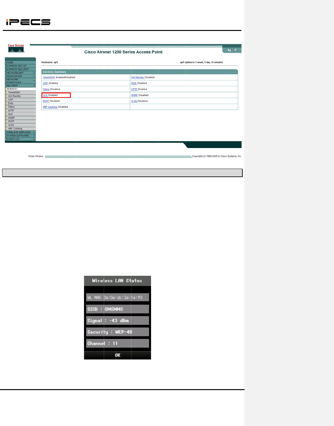
5.4
This fu
n
Strengt
h
value o
n
Notes :
Press
M
Select
8
Select
6
Technici
(The R
S
c
ument Cont
a
p
ermission o
f
5
. QoS : E
n
RSSI Mo
n
n
ction helps
h
Indicator) l
e
n
the LCD.
For better
v
M
enu
butto
n
8
.Settings
.
6
.Wireless
i
an Main Me
n
S
SI value is
WIT-400
H
a
ins proprieta
r
f
a dul
y
autho
r
n
ables
n
itoring
that the d
e
e
vel of an a
c
v
oice qualit
y
n
.
LAN Stat
n
u is displa
y
displayed o
n
<Fig
u
H
E Installati
o
ry
in
f
ormati
o
r
ized represe
n
e
aler can in
s
c
cess point
o
y
, limit of –
7
us
.
y
ed on the L
C
n
the LCD a
n
u
re .2> SIT
E
o
n Manual
o
n and ma
y
n
o
n
tative o
f
E
ri
c
29
s
tall access
o
f which the
7
5dBm is re
c
C
D.
n
d the value
E
SURVEY d
o
t be reprodu
c
c
sson-LG Co
.
point instr
u
wireless te
r
c
ommende
d
is updated
p
isplayed o
n
c
ed or copie
d
.
Ltd.
u
ment. The
r
minal is loc
k
d
.
p
eriodically.)
n
the LCD
Date: 15
d
without exp
r
RSSI (Rec
e
k
ed is displ
a
/M ar/2012
r
ess
e
ived Signa
l
a
yed as dB
m
l
m
WIT-400HE Installation Manual
Date: 15/M ar/2012
This Document Contains proprietary information and may not be reproduced or copied without express
Written permission of a duly authorized representative of Ericsson-LG Co.Ltd.
30
[Figure 3. Cell Boundary Map AP1 & AP 2]
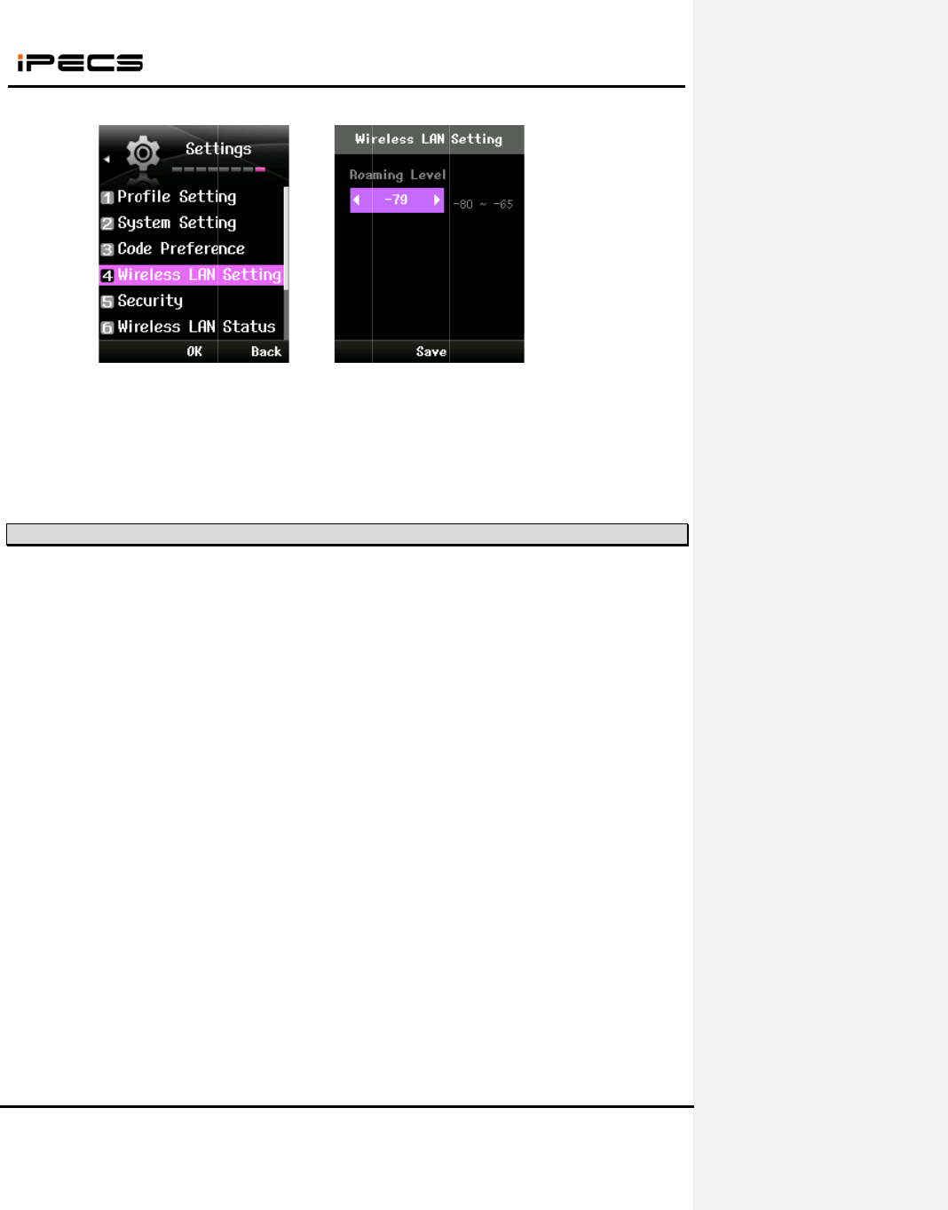
5.5 Handover
Handover feature is supported in default profile which is the first profile in profile setting menu. Profile
name and SSID of default profile is initialized “System Default” in Fig.4 . The default profile cannot be
deleted and can be edited. If you want to use this feature, you must edit the default profile include SSID,
security, network interface and so on.
[Figure 4. Default profile supported handover feature]
Roaming level can be set from -80 dBm to -65 dBm. This level may be changed according to cell
planning. The following Fig.5 is the method of setting roaming level. If you press the save button,
wireless interface is restarted.
RSSI Check
(-75dBm)
This Do
c
Written
p
Hand
o
-75dBm
5.6
1. AP T
r
If ther
e
you nee
d
So you
c
2. AP F
r
You
the AP f
r
In the h
e
retrans
m
fragmen
3. AP re
t
This
makes t
h
the relia
packet f
a
For exa
m
the retr
y
c
ument Cont
a
p
ermission o
f
o
ver is exe
c
~ -80 dBm)
Tuning P
o
r
ansmit Pow
e
e
’s heavy tr
a
d
to make th
c
an install m
o
r
agmentatio
n
can define t
r
agmentatio
n
e
avy traffic
e
m
ission mak
e
tation thres
h
t
ry limit
is the coun
t
h
e network
b
bility. By de
c
a
ster.
m
ple when t
h
y
count is too
WIT-400
H
a
ins proprieta
r
f
a dul
y
autho
r
[Figure
c
uted when
o
ints
e
r level.
a
ffic in small
e cell small
e
o
re APs in t
h
n
threshold
he maximu
m
n
threshold,
i
e
nvironment
e
s busier t
h
h
old. In case
t
of the AP
b
usier. The
v
c
reasing the
h
e user mo
v
large, it’ll in
f
H
E Installati
o
ry
in
f
ormati
o
r
ized represe
n
5. Setting ro
signal level
area, you m
e
r by decrea
s
h
e area.
m
frame size
it will be divi
d
larger pack
e
h
e network.
of Cisco AP
retransmiss
i
v
oice packet
s
retry count
t
v
es to out-of
-
f
luence to th
o
n Manual
o
n and ma
y
n
o
n
tative o
f
E
ri
c
31
aming level]
is 10dBm
ay need to i
n
s
ing the tran
s
that the A
P
d
ed by the s
e
t is more e
a
So you ca
n
it can be ad
i
on when it
s
should be
t
he load of t
h
-
range in co
n
e other calls
o
t be reprodu
c
c
sson-LG Co
.
above the
n
n
stall more
A
s
mit power l
e
P
can send
a
ize.
a
sily missed
n
reduce th
e
d
justed from
2
fails to sen
d
transmitted
o
h
e AP will b
e
n
versation, t
h
.
c
ed or copie
d
.
Ltd.
n
oise level
(
A
Ps to dispe
r
e
vel not to i
n
a
t one time.
in the wirel
e
e
retransmi
s
2
,346 to 51
2
d
packet. If
o
n real time,
e
decreased
he AP will r
e
Date: 15
d
without exp
r
(
normally si
g
r
se the calls
.
n
terfere the
a
If the data i
s
e
ss network
a
s
sion by de
c
2
.
the count i
s
it’s more i
m
and then it
e
transmit voi
/M ar/2012
r
ess
g
nal level i
s
.
In this cas
e
a
djacent AP
s
s
larger tha
n
a
nd then th
e
c
reasing th
e
s
too large i
t
m
portant tha
n
can transmi
t
ce packet. I
f
s
e
s
.
n
e
e
t
n
t
f
WIT-400HE Installation Manual
Date: 15/M ar/2012
This Document Contains proprietary information and may not be reproduced or copied without express
Written permission of a duly authorized representative of Ericsson-LG Co.Ltd.
32
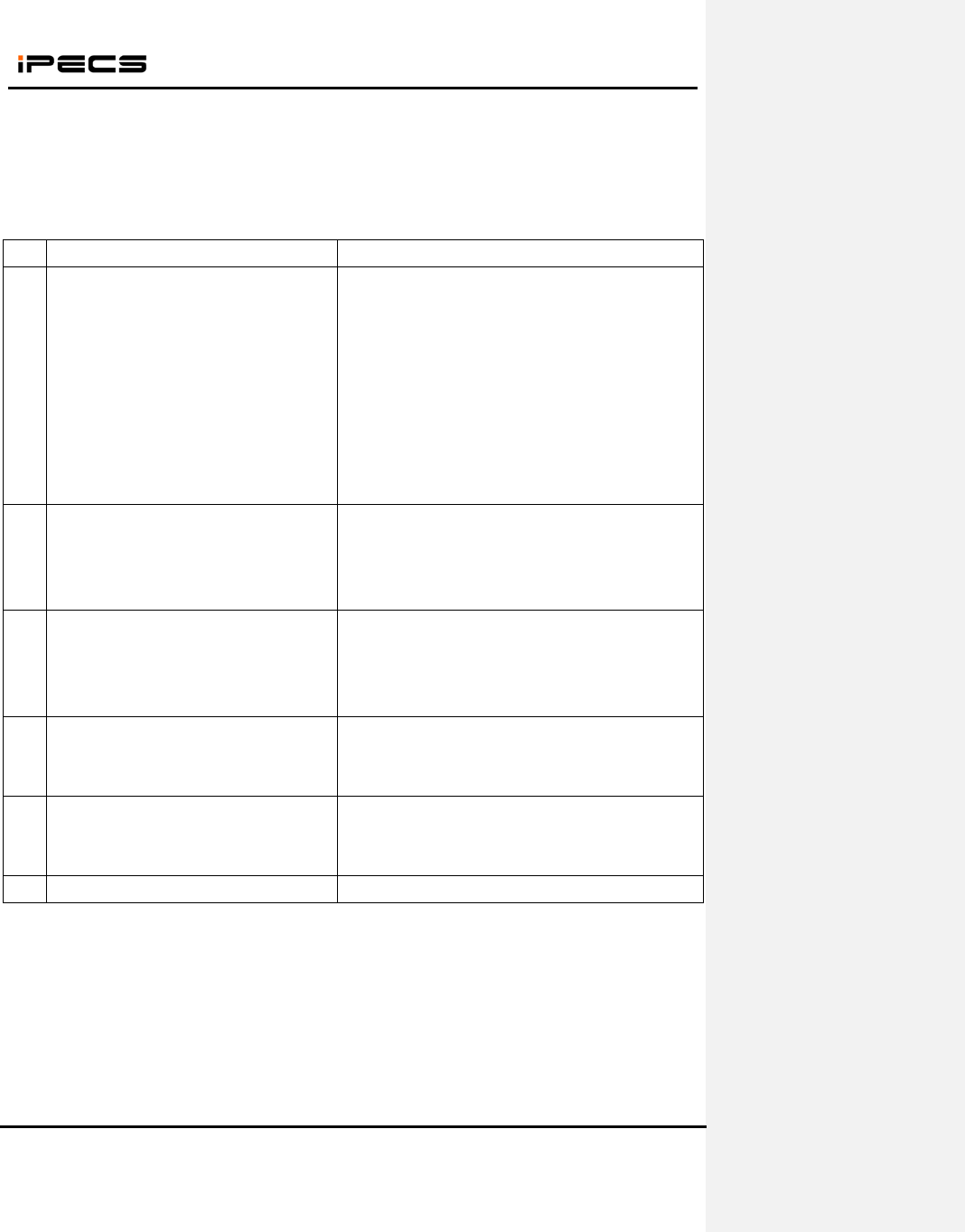
7. QoS Checklist
After you finish the installation of the system and AP, please check the voice quality by the
following items. If you find any problem on the following list, you can improve QoS by the trouble
shooting guide of each case.
No. Check list Trouble shooting guide
1 Can you make 8 calls at the same time
without voice break? (The AP should
guarantee 8 calls simultaneously)
- Review the cell planning
- Check the channel of the adjacent APs. It should be
separated more than 5 channels between adjacent
APs.
- If the AP is not in the recommended list, please
compare with the recommended one.
- If the above solution doesn’t improve the voice
quality, please change codec type to G.729 in system
admin.
2 Can you make long time call with good
voice condition?
- Review the cell planning
- Check the channel of the adjacent APs. It should be
separated more than 5 channels between adjacent
APs.
3 Can you talk across the roaming area?
(WIT-400HE guarantees roaming time
less than 500ms in well designed WLAN
network.)
- Review the cell planning. The adjacent cell is
overlapped enough?
- Check the AP support seamless roaming. We don’t
guarantee if it’s not the recommended one.
4 Can you talk without voice break moving
in the office?
- Review the cell planning. The APs cover all the area
that you are moving?
.- Check the AP connected with the phone.
5 Can you talk comfortable with the outside
subscriber?
- Check the trunk status of the system.
- If volume is too low, you can adjust gain in the
system admin.
WIT-400HE Installation Manual
Date: 15/M ar/2012
This Document Contains proprietary information and may not be reproduced or copied without express
Written permission of a duly authorized representative of Ericsson-LG Co.Ltd.
33
6. iPECS LIK Setup
6.1 MFIM S/W Version
WIT-400HE is recognized as IPKTS phone type in MFIM in iPECS LIK can be registered without any
license.
Note) iPECS LIK 50/100/300 support WIT-400HE, and iPECS LIK 600/1200 need to install VOIM board
additionally.
6.2 WIT-400HE Registration
WIT-400HE is recognized as one of the iPECS phone by iPECS MFIM. The registration can be completed
by two modes like the LIP phone.
6.2.1 MFIM Setting
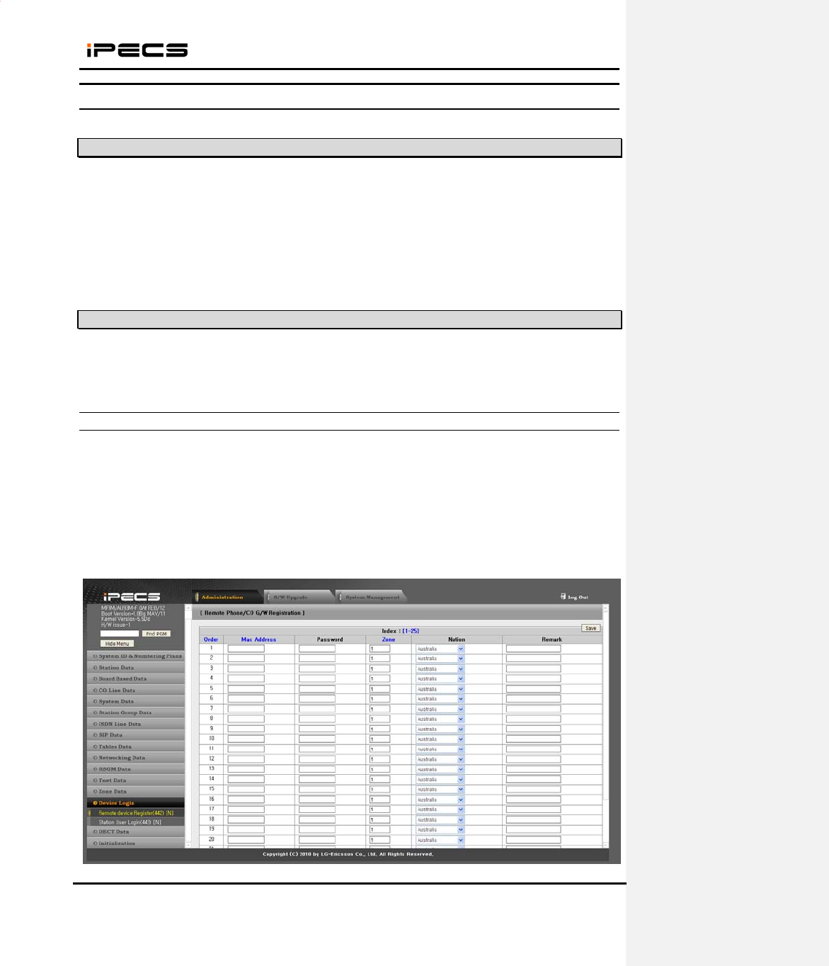
1) Set the Mac Address and Password for the WIT-400HE in Menu 442 (Station User Login).
- Mac Address : mac address of WIT-400HE
- Password : password for authentication
Note) The password should be same with phone number in which MFIM is 5.0Xx as in the picture.
WIT-400HE Installation Manual
Date: 15/M ar/2012
This Document Contains proprietary information and may not be reproduced or copied without express
Written permission of a duly authorized representative of Ericsson-LG Co.Ltd.
34
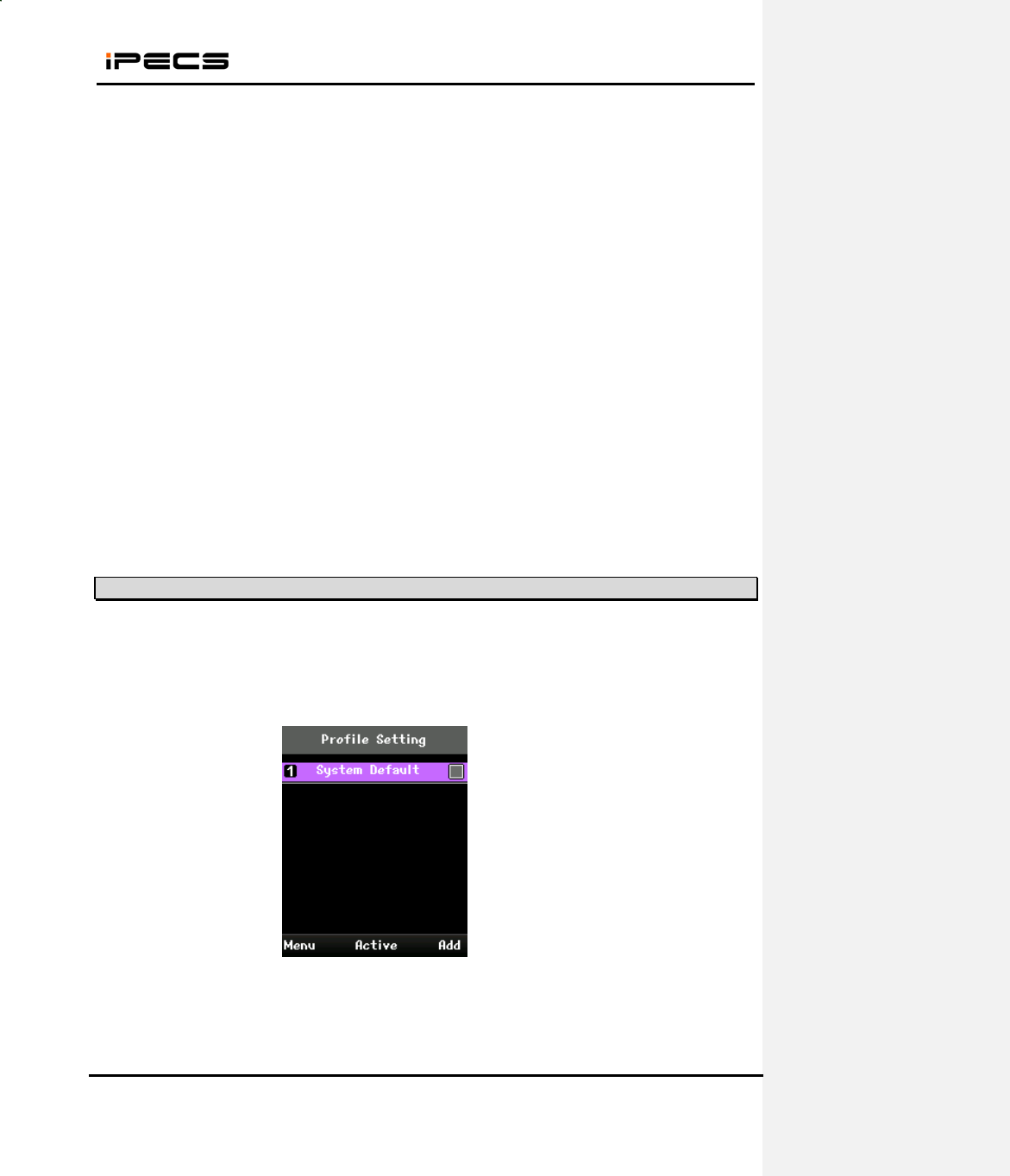
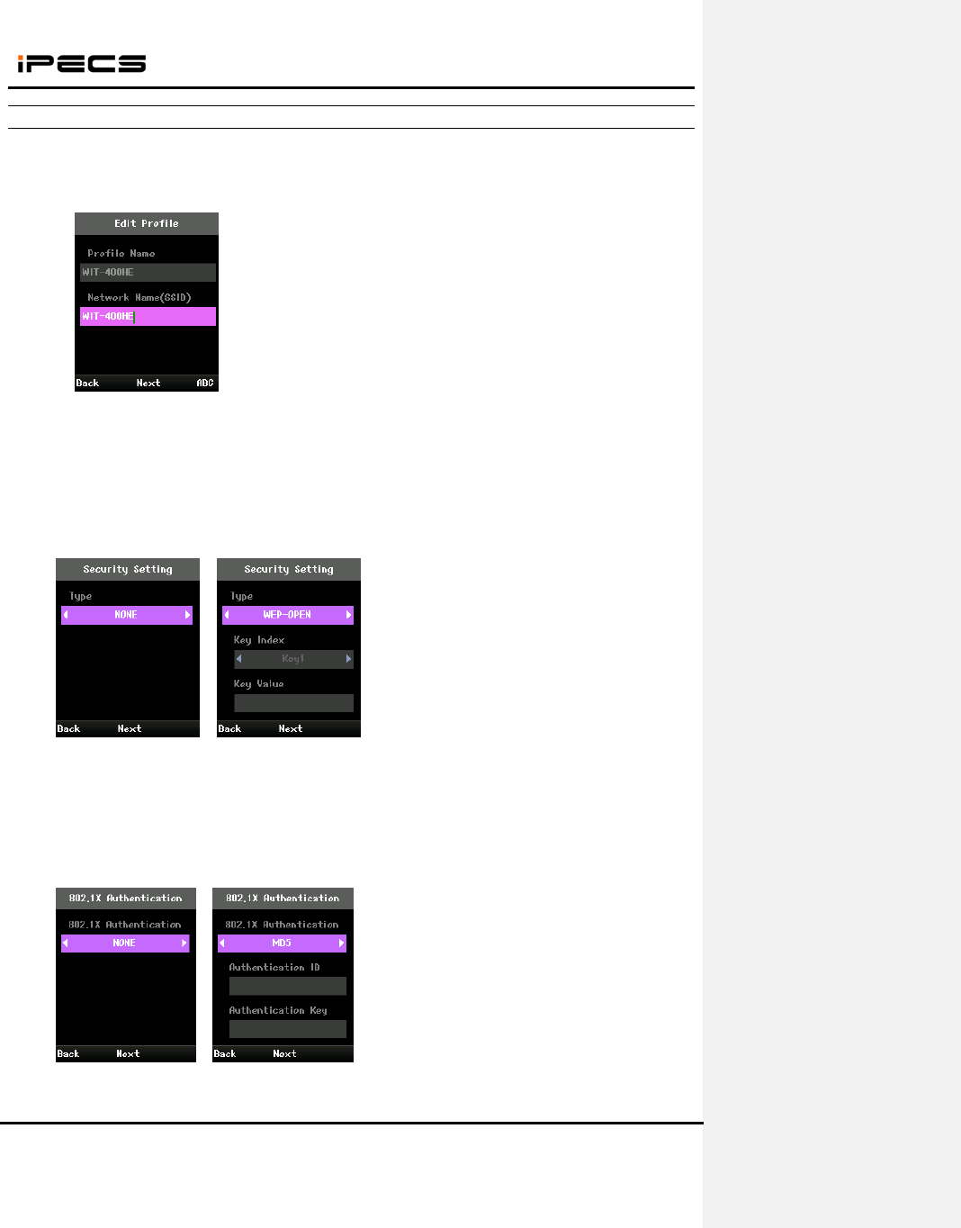
6.2.2 Profile Setting of WIT-400HE
(1) Press “AP Scanning” button on navigation up key in the idle status.
(2) Select SSID and press “Add” to add profile.
(3) Set Profile Name and Network Name (SSID) and press “Next”.
(4) Set Encryption type and press “Next”.
< Encryption type >
- None
- WEP-OPEN
- WEP-SHARED
- WPA-PSK-TKIP
- WPA-PSK-CCMP
- WPA2-PSK-TKIP
- WPA2-PSK-CCMP
(5) Set 802.1X type and press “Next”.
<802.1X type >
- None
- MD5
- TLS
- TTLS
- PEAP
This Do
c
Written
p
(6)
Se
t
<
N
-
D
-
S
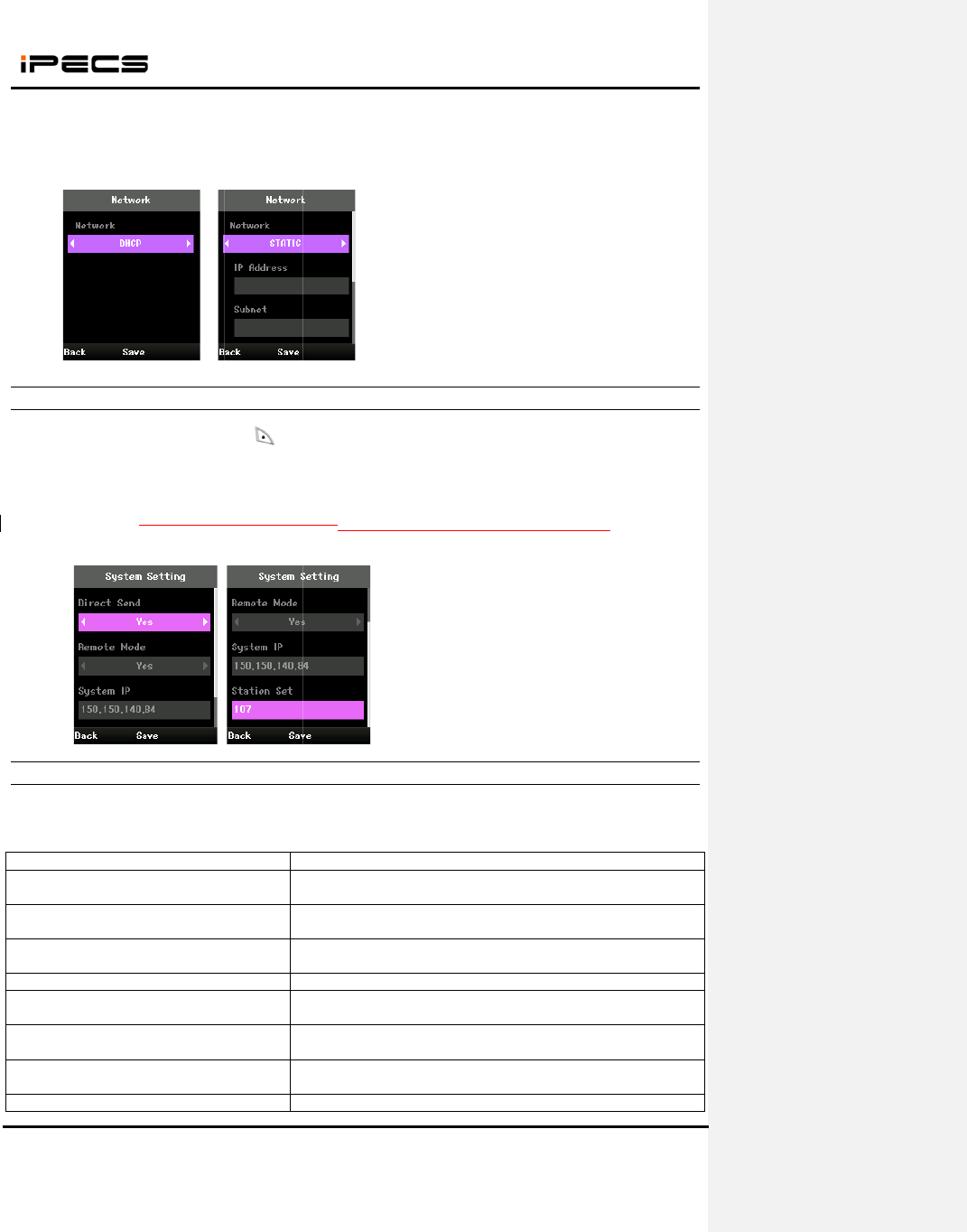
6.2.3
(1)
Se
t
- E
n
- D
i
- R
e
- S
y
- S
t
(2)
Pr
e
6.2.4
While
W
messag
e
Failed t
o
Encrypti
o
DHCP
F
Static I
P
Network
Out of r
a
Disconn
e
IP is du
p
c
ument Cont
a
p
ermission o
f
t
Network ty
p
N
etwork typ
e
D
HCP
S
TATIC
System
S
t
Registratio
n
n
ter Securit
y
i
rect Send :
Y
e
mote Mod
e
y
stem IP: iP
E
t
ation Set : t
h
e
ss “Save” a
n
Trouble
S
W
IT-400HE t
r
e
’s displaye
d
Popup
m
o
scan AP
o
n key is no
t
F
ailed
P
configure f
a
k
connection
a
nge
e
cted by ne
t
p
licated
WIT-400
H
a
ins proprieta
r
f
a dul
y
autho
r
p
e and pres
s
e
>
S
etting of
W
n
Informatio
n
y
Code ( Def
a
Y
es/No
e
: Yes/No
E
CS Syste
m
h
e idle displ
a
n
d “End” ke
y
S
hooting f
o
r
ies to regis
t
d
on the pho
n
m
essage
t
valid
a
iled
fail
t
work failure
H
E Installati
o
ry
in
f
ormati
o
r
ized represe
n
s
“Save”.
W
IT-400HE
n
at “
(M
E
a
ult : 0000 )
m
IP address
a
y for WIT-4
0
y
to start regi
o
r Registe
r
t
er to syste
m
n
e, you can
s
S
A
T
e
W
P
T
T
n
W
s
T
n
P
o
n Manual
o
n and ma
y
n
o
n
tative o
f
E
ri
c
35
E
NU) > Sett
i
to register
0
0HENo ne
e
stering to iP
r
ing Fault
m
, the follo
w
s
olve the fa
u
S
canning A
P
A
P status.
T
he encrypti
o
e
ncryption k
e
W
IT-400HE
P
lease try a
g
T
he static IP
T
he registe
r
n
etwork stat
u
W
IT-400HE
s
ignaling are
a
T
he signalin
n
etwork stat
u
P
lease chec
k
o
t be reprodu
c
c
sson-LG Co
.
i
ngs > Syst
e
e
d to define.
ECS Syste
m
w
ing error
m
u
lt referring
o
Trou
b
P
is failed. T
r
o
n key is n
o
e
y of WIT-40
didn’t recei
g
ain and if it
f
is not valid.
r
ing is fail
e
u
s and IP co
n
is off fro
m
a
.
g is failed
u
s.
k
the IP is u
s
c
ed or copie
d
.
Ltd.
e
m Setting”
It’s only for i
m
m
essage co
u
o
n the troubl
e
b
le shooting
g
r
y again an
d
o
t matched
w
0HE.
ved respon
f
ails too, ch
e
Please che
c
e
d by netw
o
n
figuration.
m
signaling
by networ
k
s
ed in other
d
Date: 15
d
without exp
r
.
PECS-CM.
u
ld be displ
a
e
shooting g
u
g
uide
d
if it fails to
o
w
ith AP’s. P
se for the
e
ck the DHC
P
c
k the IP con
o
rk failure.
area. Plea
s
k
failure. Pl
d
evice.
/M ar/2012
r
ess
a
yed. If erro
r
u
ide.
o
, check th
e
lease chec
k
IP request.
P
server.
figuration.
Check th
e
s
e move t
o
ease chec
k
r
e
k
e
o
k
WIT-400HE Installation Manual
Date: 15/M ar/2012
This Document Contains proprietary information and may not be reproduced or copied without express
Written permission of a duly authorized representative of Ericsson-LG Co.Ltd.
36
User Info not registered The system setting data is not registered on the system.
Please set the data to register, such as Direct Send ,Remote
mode, System IP and so on.
Register failed. Please check user info System responded error message on registering request.
Please check System Setting information such as Direct
Send ,Remote mode, System IP and so on.
Please check phone number The phone number is not defined on the system. Please
check the system login IDs on Menu 442.
Can't register to system System responded error message on registering request.
Please check the iPECS System ’s Mac address and
password.
This Do
c
Written
p
7.
7.1
WIT-40
0
license.
7.2
7.2.1
1) Set t
h
-
-
Note) T
h
7.2.2
(1)
Se
t
- E
n
- D
i
- R
e
- S
y
- S
t
(2)
Pr
e
c
ument Cont
a
p
ermission o
f
iPECS
CM
V
ersi
o
0
HE is recog
WIT-400
H
iPECS C
M
h
e Mac Addr
e
Mac Addre
s
Password :
h
e passwor
d
System
S
t
Registratio
n
n
ter Securit
y
i
rect Send :
Y
e
mote Mod
e
y
stem IP: iP
E
t
ation Set : t
h
e
ss “Save” a
n
WIT-400
H
a
ins proprieta
r
f
a dul
y
autho
r
CM Se
t
o
n
nized as IP
K
H
E Registr
a
M
Setting
e
ss and Pas
s
s : mac add
r
password fo
d
should b
e
S
etting of
W
n
Informatio
n
y
Code ( Def
a
Y
es/No
e
: Yes/No
E
CS Syste
m
h
e WIT-400
H
n
d “End” ke
y
H
E Installati
o
ry
in
f
ormati
o
r
ized represe
n
tup
K
TS phone t
y
a
tion
sword for th
e
r
ess of WIT-
4
r authentica
t
e
same with
W
IT-400HE
n
at “
(M
E
a
ult : 0000 )
m
IP address
H
E phone n
u
y
to start regi
o
n Manual
o
n and ma
y
n
o
n
tative o
f
E
ri
c
37
y
pe in iPEC
S
e
WIT-400H
E
4
00HE
t
ion
phone nu
m
E
NU) > Sett
i
to register
u
mber(ID)
stering to iP
o
t be reprodu
c
c
sson-LG Co
.
S
CM. WIT-
4
E
in Menu 4
4
m
ber in whic
i
ngs > Syst
e
ECS Syste
m
c
ed or copie
d
.
Ltd.
4
00HE can
b
4
2 (Station
U
h MFIM is
5
e
m Setting”
m
Date: 15
d
without exp
r
b
e registere
d
U
ser Login).
5
.0Xx as in t
h
.
/M ar/2012
r
ess
d
without an
y
h
e picture.
y