Ericsson Wi Fi 20180001 Radio Module User Manual BelAir20 manual
Ericsson Wi-Fi Radio Module BelAir20 manual
user manual

BelAir20
BelAir20
Quick Install Guide
Document Date: January 7, 2009
Document Number: BDTQ02001-A01
Document Status: Standard
Security Status: Confidential
Customer Support: 613-254-7070
1-877-BelAir1 (235-2471)
techsupport@belairnetworks.com
c Copyright 2009 by BelAir Networks.
The information contained in this document is confidential and proprietary to BelAir Networks. Errors and Omissions Excepted.
Specifications may be subject to change. All trademarks are the property of their respective owners.
Protected by U.S. Patents: 7,171,223, 7,164,667, 7,154,356, 7,030,712 and D501,195. Patents pending in the U.S. and other countries.
BelAir Networks, the BelAir Logo, BelAir200, BelAir100, BelAir100S, BelAir100C, BelAir100T, BelAir20, BelView and BelView NMS are trademarks of BelAir
Networks Inc.
Page 1 of 5

BelAir20 Quick Install Guide Introduction
Introduction
The BelAir20 is a Wi-Fi access point that meets IEEE 802.11n draft 2.0
standards. It is fully interoperable with older 802.11a/b/g standards, providing a
transparent, wireless high speed data communication between the wired LAN
and fixed or mobile devices. The unit includes three detachable dual-band
2.4/5 GHz antennas with the option to attach higher specification external
antennas that boost network coverage. A power adapter and all required
mounting hardware is also included.
Package Contents The BelAir20 package includes:
# BelAir20 dual radio access point
# Power adapter-input: 100-240 VAC; output: 48 VDC
# Four stick-on rubber feet
# BelAir20 wall or ceiling mounting bracket
# Four M3.5x40 pan head Phillips screws for wall mounting
# Four 6x35 nylon wall mount anchors
# Two tie wraps to secure DC power and Ethernet cables
# One 10-32 nut and #10 lock washer for ground stud
# Two twist-on T-rail support clips and T-rail spacers
# Quick Installation Guide
Inform your dealer if there are any incorrect, missing or damaged parts. If
possible, retain the carton, including the original packing materials. Use them
again to repack the product in case there is a need to return it.
January 7, 2009 Confidential Page 2 of 5
Document Number BDTQ02001-A01 Standard
BelAir20 Quick Install Guide Introduction
Warning
Do not connect a PoE or DC powered Ethernet interface to
the Console Port. See the BelAir20 User Guide for details.
Antennas The BelAir20 includes three dual-band external diversity Multiple Input Multiple
Output (MIMO) antennas. The antennas transmit the outgoing signal as a
toroidal sphere (doughnut shaped), with the coverage extending most in a
direction perpendicular to the antenna. The antenna should be adjusted to an
angle that provides the appropriate coverage for the service area.
External Antenna The BelAir20 supports external antennas for improving the coverage of the
Connector signal. The antennas supplied with the unit screw off in a clockwise manner and
can be replaced with alternative antennas that improve or shape the coverage
area.
Security The BelAir20 provides a security lock slot that accepts a lock with a body up to
3/4 inches (approx. 19 mm) wide. BelAir Networks recommends using Master
Lock’s 120T lock. It also provides a Kensington lock feature and a fastening
screw.
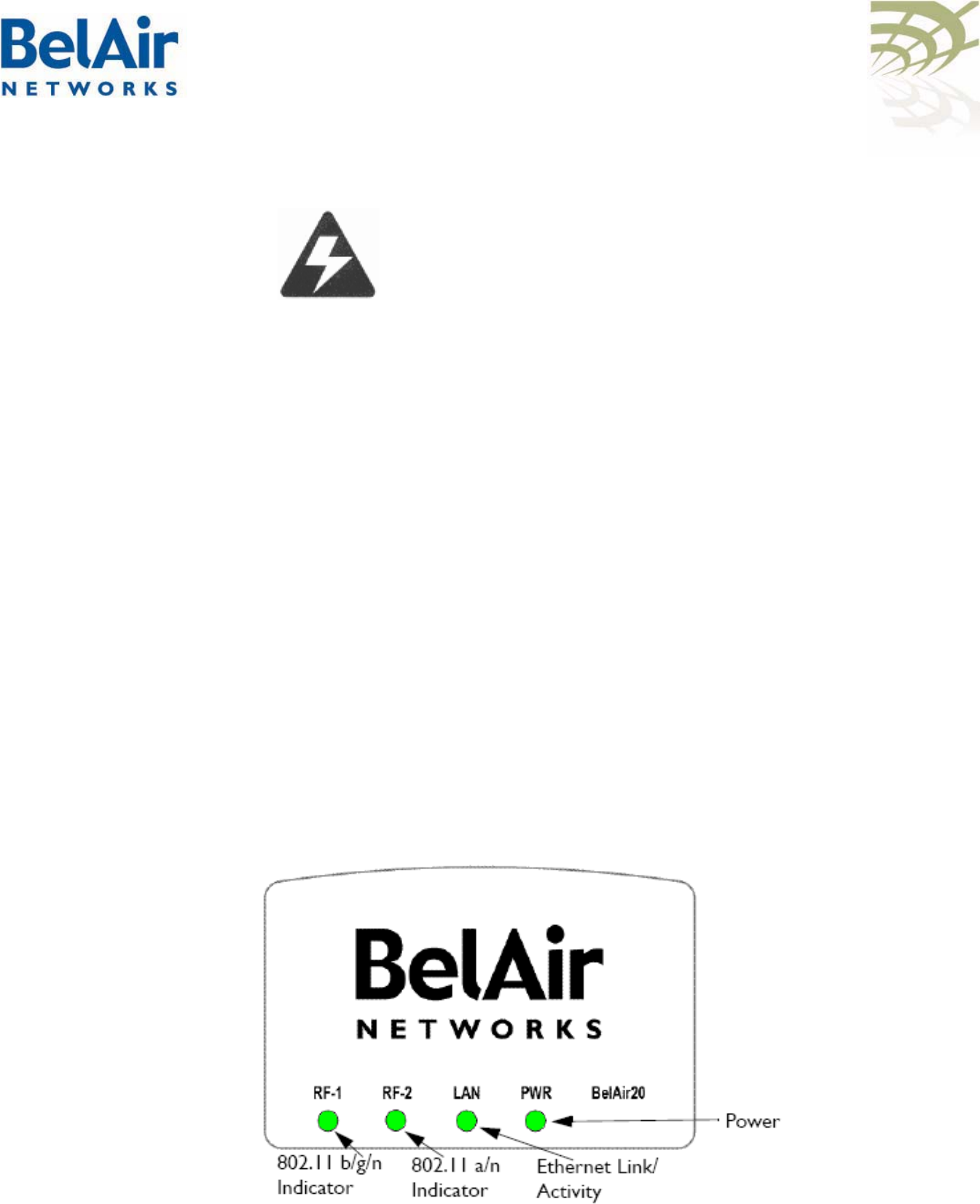
LED Indicators The BelAir20 includes four status LED indicators described in Figure 3 and
Table 1 on page 5.
Figure 3: LEDs
Document Number BDTQ02001-A01 Standard
January 7, 2009 Confidential Page 3 of 5
This equipment has been tested and found to comply with the limits for a Class B digital device, pursuant to Part 15 of the FCC Rules. These limits are designed to provide
reasonable protection against harmful interference in a residential installation. This equipment generates, uses and can radiate radio frequency energy and, if not installed
and used in accordance with the instructions, may cause harmful interference to radio communications. However, there is no guarantee that interference will not occur in a
particular installation. If this equipment does cause harmful interference to radio or television reception, which can be determined by turning the equipment off and on, the
user is encouraged to try to correct the interference by one of the following measures:
● Reorient or relocate the receiving antenna.
● Increase the separation between the equipment and receiver.
● Connect the equipment into an outlet on a circuit different from that to which the receiver is connected.
● Consult the dealer or an experienced radio/TV technician for help.
FCC Caution: Any changes or modifications not expressly approved by the party responsible for compliance could void the user’s authority to operate this equipment.
This device complies with Part 15 of the FCC Rules. Operation is subject to the following two conditions: (1) This device may not cause harmful interference, and (2) this
device must accept any interference received, including interference that may cause undesired operation.
For product available in the USA/Canada market, only channel 1~11 can be operated. Selection of other channels is not possible.
This device and its antenna(s) must not be co-located or operation in conjunction with any other antenna or transmitter.
FCC Caution: Any changes or modifications not expressly approved by the party responsible for compliance could void the user’s authority to operate this equipment.
IMPORTANT NOTE:
FCC Radiation Exposure Statement:
This equipment complies with FCC radiation exposure limits set forth for an uncontrolled environment. This equipment should be installed and operated with minimum
distance 20cm between the radiator & your body.
This device is intended only for OEM integrators under the following conditions:
This module is intended for OEM integrator. The OEM integrator is still responsible for the FCC compliance requirement of the end product, which integrates this module.
20cm minimum distance has to be able to be maintained between the antenna and the users for the host this module is integrated into. Under such configuration, the FCC
radiation exposure limits set forth for an population/uncontrolled environment can be satisfied.
Any changes or modifications not expressly approved by the manufacturer could void the user's authority to operate this equipment.
USERS MANUAL OF THE END PRODUCT:
In the users manual of the end product, the end user has to be informed to keep at least 20cm separation with the antenna while this end product is installed and operated.
The end user has to be informed that the FCC radio-frequency exposure guidelines for an uncontrolled environment can be satisfied. The end user has to also be informed
that any changes or modifications not expressly approved by the manufacturer could void the user's authority to operate this equipment. If the size of the end product is
smaller than 8x10cm, then additional FCC part 15.19 statement is required to be available in the users manual: This device complies with Part 15 of FCC rules. Operation is
subject to the following two conditions: (1) this device may not cause harmful interference and (2) this device must accept any interference received, including interference
that may cause undesired operation.
LABEL OF THE END PRODUCT:
The final end product must be labeled in a visible area with the following " Contains TX FCC ID: RAR20180001 ". If the size of the end product is larger than 8x10cm, then
the following FCC part 15.19 statement has to also be available on the label: This device complies with Part 15 of FCC rules. Operation is subject to the following two
conditions: (1) this device may not cause harmful interference and (2) this device must accept any interference received, including interference that may cause undesired
operation.

BelAir20 Quick Install Guide Introduction
Introduction
The BelAir20 is a Wi-Fi access point that meets IEEE 802.11n draft 2.0
standards. It is fully interoperable with older 802.11a/b/g standards, providing a
transparent, wireless high speed data communication between the wired LAN
and fixed or mobile devices. The unit includes three detachable dual-band
2.4/5 GHz antennas with the option to attach higher specification external
antennas that boost network coverage. A power adapter and all required
mounting hardware is also included.
Package Contents The BelAir20 package includes:
# BelAir20 dual radio access point
# Power adapter-input: 100-240 VAC; output: 48 VDC
# Four stick-on rubber feet
# BelAir20 wall or ceiling mounting bracket
# Four M3.5x40 pan head Phillips screws for wall mounting
# Four 6x35 nylon wall mount anchors
# Two tie wraps to secure DC power and Ethernet cables
# One 10-32 nut and #10 lock washer for ground stud
# Two twist-on T-rail support clips and T-rail spacers
# Quick Installation Guide
Inform your dealer if there are any incorrect, missing or damaged parts. If
possible, retain the carton, including the original packing materials. Use them
again to repack the product in case there is a need to return it.
January 7, 2009 Confidential Page 4 of 5
Document Number BDTQ02001-A01 Standard
This Class B digital apparatus complies with Canadian ICES-003.
Cet appareil numérique de la classe B conforme á la norme NMB-003 du Canada.
Operation is subject to the following two conditions: (1) this device may not cause interference, and (2) this device
must accept any interference, including interference that may cause undesired operation of the device.
To reduce potential radio interference to other users, the antenna type and its gain should be so chosen that the
equivalent isotropically radiated power (e.i.r.p) is not more than that permitted for successful communication.
IMPORTANT NOTE: This module is intended for OEM integrator. The OEM integrator is still responsible for
the IC compliance requirement of the end product, which integrates this module.
20cm minimum distance has to be able to be maintained between the antenna and the users for the host this module
is integrated into. Under such configuration, the IC RSS-102 radiation exposure limits set forth for an population/
uncontrolled environment can be satisfied.
Any changes or modifications not expressly approved by the manufacturer could void the user's authority to operate
this equipment.
USERS MANUAL OF THE END PRODUCT: In the users manual of the end product, the end user has to be
informed to keep at least 20cm separation with the antenna while this end product is installed and operated. The end
user has to be informed that the IC radio-frequency exposure guidelines for an uncontrolled environment can be
satisfied. The end user has to also be informed that any changes or modifications not expressly approved by the
manufacturer could void the user's authority to operate this equipment. IC statement is required to be available in
the users manual: This Class B digital apparatus complies with Canadian ICES-003. Operation is subject to the
following two conditions: (1) this device may not cause harmful interference and (2) this device must accept any
interference received, including interference that may cause undesired operation.
LABEL OF THE END PRODUCT: The final end product must be labeled in a visible area with the following "
Contains TX IC : 4674A-20180001 ".
IMPORTANT NOTE:
IC Radiation Exposure Statement: This equipment complies with IC RSS-102 radiation exposure limits set forth for
an uncontrolled environment. This equipment should be installed and operated with minimum distance 20cm
between the radiator & your body.

BelAir20 Quick Install Guide Installing the BelAir20
Otherwise, the BelAir20 can derive its operating power directly from the RJ-45
p
ort when connected to a device that provides IEEE 802.3af compliant Powe
r
over Ethernet (PoE).
Warning
The BelAir20 must be connected to a Power over Ethernet
(POE) IEEE 802.3af compliant power source, or an IEC/EN
60950-1 compliant power limited source.
Note: If the BelAir20 is connected to both a PoE source device and an AC
power source, AC will be disabled.
5 Observe the Self Test - When you power on the BelAir20, verify that the
Power indicator stops flashing and remains on, and that the other indicators
start functioning as described under “LED Indicators” on page 4.
If the PWR LED does not stop flashing, the self test has not completed
correctly. Refer to “LED Indicators” on page 4.
6 Connect your network to the RJ-45 port on the back panel with Category
5E or better UTP Ethernet cable. When the BelAir20 and the connected
device are powered on, the Ethernet Link LED should light indicating a valid
network connection.
7 Position the Antennas - The antennas should be oriented so that the radio
coverage pattern fills the intended horizontal space. For example, if the
BelAir20 is mounted on a horizontal surface, the center antenna should be
vertical with the outer antennas pointed left and right at about 45 °
respectively. See Figure 1 on page 3.
Configuring the You can configure the BelAir20 through its Web interface or Command Line
Interface (CLI). Refer to the BelAir20 User Guide for complete details.
BelAir20
BelAir Networks Inc. General Information Sales Visit us on the web at:
603 March Road info@belairnetworks.com sales@belairnetworks.com
Kanata, Ontario www.belairnetworks.com
Canada Technical Support
K2K 2M5 techsupport@belairnetworks.com
1-877-BelAir1 (235-2471)
613-254-7070
Document Number BDTQ02001-A01 Standard
January 7, 2009 Confidential Page 5 of 5