Ericsson Receiver Rx8000 Users Manual Series Receivers
RX8000 to the manual 1e3534b4-d043-4f91-8179-47d3433b9d6d
2015-02-06
: Ericsson Ericsson-Receiver-Rx8000-Users-Manual-540903 ericsson-receiver-rx8000-users-manual-540903 ericsson pdf
Open the PDF directly: View PDF ![]() .
.
Page Count: 236 [warning: Documents this large are best viewed by clicking the View PDF Link!]
- TP_RE_e10274_00_2
- TP_RE_e10274_01_2
- 1 Introduction
- Chapter 1
- Contents
- 1.1 Introduction
- 1.2 Summary of Features
- 1.3 The Satellite Receiver
- 1.4 The Telco Receiver/Decoder
- 1.5 Construction
- 1.6 Front Panel
- 1.7 Rear Panels
- TP_RE_e10274_02_2
- 2 Installing the Equipment
- Chapter 2
- Contents
- 2.1 Read This First!
- 2.2 Preliminary Checks
- 2.3 Installing the Equipment
- 2.4 EMC Compliance Statements
- 2.5 AC Supply Operating Voltage and Fusing – SafetyInformation
- 2.6 Protective Earth/Technical Earth
- 2.7 Signal Connections
- 2.7.1 General
- RF IN Connector (RX8200 and RX8320 only)
- 2.7.3 ASI OUT Connector (RX8310/15/20 only)
- 2.7.4 ASI/SDI OUT Connector (RX8200 and RX8330 only)
- 2.7.5 ASI/HD-SDI/SD-SDI OUT Connector (RX8200 only)
- 2.7.6 CVBS Connector
- 2.7.7 AUDIO/AUDIO OUT Connector
- 2.7.8 ETHERNET/CONTROL Connector
- 2.7.9 ASI IN Connector
- 2.7.10 COMPONENT VIDEO Connector (RX8200 only)
- 2.7.11 DATA OUT Connector
- 2.7.12 ALARM Connector
- 2.7.13 RS232/RS485 REMOTE Connector
- TP_RE_e10274_03_2
- 3 Front Panel Control
- Chapter 3
- Contents
- 3.1 Introduction
- 3.2 Powering the Equipment
- 3.3 Using the Front Panel Controls
- 3.4 Example Configuration
- 3.5 Front Panel Menus
- 3.5.1 1 System
- 3.5.1.1 1.1 Network
- 3.5.1.2 1.2 Build
- 3.5.1.2.1 1.2.1 SW Version
- 3.5.1.2.2 1.2.2 PS Version
- 3.5.1.2.3 1.2.3 SD FPGA Version
- 3.5.1.2.4 1.2.4 HD FPGA Version (RX8200 only)
- 3.5.1.2.5 1.2.5 Audio DSP Version (RX8200 only)
- 3.5.1.2.6 1.2.6 TS FPGA Version (on RX8200 – Menu 1.2.4 on RX83XX)
- 3.5.1.2.7 1.2.7 HW ID
- 3.5.1.2.8 1.2.8 422 FW (Option Card)
- 3.5.1.2.9 1.2.9 422 SW (Option Card)
- 3.5.1.3 1.3 USN
- 3.5.1.4 1.4 Factory
- 3.5.1.5 1.5 Front Panel (FP)
- 3.5.2 2 Input (Satellite Input Card RX8200/HWO/DVBS2)
- 3.5.3 2 Input (I/P Input Card RX8XXX/HWO/IP/GIGE)
- 3.5.4 2 Input (8VSB Input Card RX8320/HWO/8VSB)
- 3.5.5 2 Input (G703 ATM Input Card RX8XXX/HWO/G703)
- 3.5.6 3 Service
- 3.5.7 4 CA Systems
- 3.5.7.1 4.1 Service Table
- 3.5.7.2 4.2 Director
- 3.5.7.2.1 4.2.1 Over Air Message
- 3.5.7.2.2 4.2.2 Broadcaster ID
- 3.5.7.2.3 4.2.3 Unique Hardware ID
- 3.5.7.2.4 4.2.4 Manuf ID
- 3.5.7.2.5 4.2.5 Download Status
- 3.5.7.2.6 4.2.6 Enter New PIN
- 3.5.7.2.7 4.2.7 Reset PIN
- 3.5.7.2.8 4.2.8 Over Air Extd Carrier Timeout
- 3.5.7.2.9 4.2.9 Over Air Control
- 3.5.7.2.10 4.2.10 Power-up Carrier
- 3.5.7.2.11 4.2.11 Emergency Home Carrier
- 3.5.8 5 Output
- 3.5.9 6 Presets
- 3.5.1 1 System
- TP_RE_e10274_04_2
- TP_RE_e10274_05_2
- 5 Web Browser Control
- Chapter 5
- Contents
- 5.1 Introduction
- 5.2 Web Pages
- 5.2.1 Status
- 5.2.2 Device Info
- 5.2.3 Alarms
- 5.2.4 Customization
- 5.2.5 CA
- 5.2.6 Input Main Page (Satellite Input Card RX8200/HWO/DVBS2 fitted)
- 5.2.7 Input Main Page (I/P Input Card RX8XX/HWO/GIGE fitted)
- 5.2.8 Input (8VSB Input Card RX8320/HWO/8VSB fitted)
- 5.2.9 Input (G.703 ATM Input Card RX8XXX/HWO/G.703 fitted)
- 5.2.10 Service Plus
- 5.2.11 Decode
- 5.2.12 Output
- 5.2.13 Download
- 5.2.14 SNMP
- 5.2.15 Presets
- 5.2.16 Save/Load
- 5.2.17 Help
- TP_RE_e10274_06_2
- 6 Options
- Chapter 6
- Contents
- 6.1 Hardware and Software Options
- 6.1.1 DVB-S2 Input Card (RX8200/HWO/DVBS2)
- 6.1.2 8-VSB Input Card (RX83XX/HWO/8VSB)
- 6.1.3 Gigabyte 100/1000Base T Ethernet (RX8XXX/HWO/IP/GIGE)
- 6.1.4 G.703 ATM Input Card (RX8XXX/HWO/G703)
- 6.1.5 MPEG-2 4:2:2 SD Decoding Card (RX82XX/HWO/MP2/422)
- 6.1.6 MPEG-4 AVC 4:2:2 Decoding Card (RX8200/BAS/2)
- 6.1.7 IP Output Card (RX8XXX/HWO/IP/OUT)
- 6.1.8 SD Video and ASI Output Card (RX8200/HWO/SD)
- 6.1.9 HD and SD Video and ASI Output Card (RX8200/HWO/HD/3G)
- 6.1.10 High Quality Down-conversion (RX8200/HWO/HQDCONV)
- 6.1.11 RS232 Low Speed Asynchronous Data and Remote Control (RX8200/HWO/RS232)
- 6.1.12 Balanced Audio Output Card (RX8200/HWO/BAL/AUD)
- 6.1.13 XLR Terminal Audio Break-Out Cable (RX8XXX/CABLE/XLR)
- 6.1.14 Screw Terminal Audio Break-Out Cable (RX8XXX/CABLE/SCRTRM)
- 6.2 Software Enabled Options
- 6.2.1 DVB-S2 QPSK (RX8XXX/SWO/DVBS2/QPSK)
- 6.2.2 DVB-S2 8PSK (RX8XXX/SWO/DVBS2/8PSK)
- 6.2.3 DVB-S2 Low Symbol Rate (RX8XXX/SWO/DVBS2/LSYM)
- 6.2.4 MPEG-2 SD Decode (RX8XXX/SWO/MPEG2/SD)
- 6.2.5 MPEG-2 HD Decode (RX8XXX/SWO/MPEG2/HD)
- 6.2.6 MPEG-4 AVC SD Decode (RX8XXX/SWO/MPEG4/SD)
- 6.2.7 MPEG-4 AVC HD Decode (RX8XXX/SWO/MPEG4/HD)
- 6.2.8 MPEG-2/4 AVC SD 4:2:0 Decode (RX8XXX/SWO/MP2/MP4/SD)
- 6.2.9 MPEG-2/4 AVC HD 4:2:0 Decode (RX8XXX/SWO/MP2/MP4/SD/HD)
- 6.2.10 Single-Service Filtering (RX8XXX/SWO/SING/SERVFILT)
- 6.2.11 Multi-Service Filtering (RX8XXX/SWO/MULTI/SERVFILT)
- 6.2.12 High-Speed Data Output (RX8XXX/SWO/IP/DATA)
- 6.2.13 Password Protection of Web Browser (RX8XXX/SWO/PW)
- 6.2.14 IP Transport Stream Output (RX8XXX/SWO/IP/OUT)
- 6.2.15 Director (RX8XXX/SWO/DIR5)
- 6.2.16 Director Multi-Service Decryption (RX8XXX/SWO/DIR5/MSD)
- 6.2.17 Multi-Service CAM Decryption (RX8XXX/SWO/MSD)
- 6.2.18 Serial Data Interface (RX8XXX/SWO/SDI)
- 6.2.19 Dolby Digital Decode (RX8XXX/SWO/AC3)
- 6.2.20 AAC Audio Decode (RX8XXX/SWO/AAC)
- 6.2.21 DVB-S2 16APSK (RX8XXX/SWO/DVBS2/16APSK)
- 6.2.22 Null Packet Detection Redundancy Switching (RX8XXX/SWO/DVBS2/NULL)
- 6.2.23 DVB Common Interface (RX8XXX/SWO/CI)
- 6.2.24 BISS CA (RX8XXX/SWO/BISS)
- 6.2.25 BISS Multi-Service CA (RX8XXX/SWO/BISS/MSD)
- 6.2.26 SMPTE 2022 Pro-MPEG FEC (RX8200/SWO/IP/PROMPEG)
- 6.2.27 MPEG-2 SD 4:2:2 Decoding (RX8200/SWO/MP2/SD/422)
- 6.2.28 MPEG-2 HD 4:2:2 Decoding (RX8200/SWO/MP2/HD/422)
- 6.2.29 MPEG-4 SD 4:2:2 Decoding (RX8200/SWO/MP4/SD/422)
- 6.2.30 MPEG-4 HD 4:2:2 Decoding (RX8200/SWO/MP4/HD/422)
- 6.2.31 Down-Conversion (RX8200/SWO/DCONV)
- 6.2.32 Up-Conversion (RX8200/SWO/UPCONV)
- 6.2.33 Cross-Conversion (RX8200/SWO/XCONV)
- 6.2.34 Framesync (RX8200/SWO/FSYNC)
- 6.2.35 4 x Audio Capability (RX8200/SWO/4AUD)
- 6.2.36 Low Latency Decode (RX8200/SWO/LDELAY)
- 6.1 Hardware and Software Options
- TP_RE_e10274_07_2
- TP_RE_e10274_AA_2
- TP_RE_e10274_AB_2
- TP_RE_e10274_AC_2
RX8000 Series Receivers
Software Version 4.3.2
REFERENCE GUIDE
EN/LZT 790 0005 R1A

RX8000 Series Receivers
ENGLISH (UK) - READ THIS FIRST!
If you do not understand the contents of this manual. DO NOT OPERATE
THIS EQUIPMENT. Also, translation into any EC official language of this
manual can be made available, at your cost.
ITALIANO - LEGGERE QUESTO AVVISO PER PRIMO!
Se non si capisce il contenuto del presente manuale. NON UTILIZZARE
L’APPARECCHIATURA.. È anche disponibile la versione italiana di questo
manuale, ma il costo è a carico dell’utente.
NEDERLANDS - LEES DIT EERST!
Als u de inhoud van deze handleiding niet begrijpt. STEL DEZE
APPARATUUR DAN NIET IN WERKING. U kunt tevens, op eigen kosten,
een vertaling van deze handleiding krijgen.
SVENSKA - LÄS DETTA FÖRST!
Om Ni inte förstår informationen i denna handbok. ARBETA DÅ INTE MED
DENNA UTRUSTNING. En översättning till detta språk av denna handbok
kan också anskaffas, på Er bekostnad.
SUOMI - LUE ENNEN KÄYTTÖÄ!
Jos et ymmärrä käsikirjan sisältöä. ÄLÄ KÄYTÄ LAITETTA. Käsikirja
voidaan myös suomentaa asiakkaan kustannuksella.
PORTUGUÊS - LEIA O TEXTO ABAIXO ANTES DE MAIS NADA!
Se não compreende o texto deste manual. NÃO UTILIZE O
EQUIPAMENTO. O utilizador poderá também obter uma tradução do
manual para o português à própria custa.
DANSK - LÆS DETTE FØRST!
Udstyret må ikke betjenes. MEDMINDRE DE TIL FULDE FORSTÅR
INDHOLDET AF DENNE HÅNDBOG. Vi kan også for Deres regning levere
en dansk oversættelse af denne håndbog.
FRANÇAIS - AVANT TOUT, LISEZ CE QUI SUIT!
Si vous ne comprenez pas les instructions contenues dans ce manuel. NE
FAITES PAS FONCTIONNER CET APPAREIL. En outre, nous pouvons
vous proposer, à vos frais, une version française de ce manuel.
ΕΛΛΗΝΙΚΑ - ΔΙΑΒΑΣΤΕ ΠΡΩΤΑ ΑΥΤΟ!
Αν δεν καταλάβετε το περιεχόμενο αυτού του βοηθήματος/εγχειριδίου. ΜΗΝ
ΛΕΙΤΟΥΡΓΗΣΕΤΕ ΑΥΤΟΝ ΤΟΝ ΕΞΟΠΛΙΣΜΟ. Επίσης, αυτό το εγχειρίδιο
είναι διαθέσιμο σε μετάφραση σε αυτή τη γλώσσα και μπορείτε να το
αγοράσετε.
DEUTSCH - LESEN SIE ZUERST DIESEN HINWEIS!
Sollte Ihnen der Inhalf dieses Handbuches nicht klar verständlich sein,
dann. BEDIENEN SIE DIESE GERÄTE NICHT! Eine Übersetzung des
Handbuches in diese Sprache ist gegen Berechnung lieferbar.
ESPAÑOL - LEA ESTE AVISO PRIMERO!
Si no entiende el contenido de este manual. NO OPERE ESTE EQUIPO.
Podemos asimismo suministrarle una traducción de este manual al (idioma)
previo pago de una cantidad adicional que deberá abonar usted mismo.
Copyright
© Copyright Ericsson AB 2011. All rights reserved.
Disclaimer
No part of this document may be reproduced in any form without the written permission of the
copyright owner.
The contents of this document are subject to revision without notice due to continued progress in
methodology, design and manufacturing. Ericsson shall have no liability for any error or damage of
any kind resulting from the use of this document.
EN/LZT 790 0005 R1A 2011-03-30
ii
Contents
EN/LZT 790 0005 R1A 2011-03-30
iii
Contents
Chapter 1: Introduction
This chapter identifies the equipment versions covered by this manual, describes
the purpose of the equipment and provides a summary of features, controls and
indicators.
Chapter 2: Installing the Equipment
This chapter provides a guide to the installation requirements, gives detailed
procedures for the installation and configuration of the equipment including
important safety information and provides details of connectors.
Chapter 3: Front Panel Control
This chapter details the power up/down procedures and describes the Front Panel
LCD menus used for setting-up, configuring and operating the equipment.
Chapter 4: Remote Control
This chapter describes the different ways in which the equipment may be configured
and operated remotely.
Chapter 5: Web Browser Control
This chapter describes the Web Browser graphical user interface used for detailed
configuration and operation of the equipment.
Chapter 6: Options
This chapter describes the available hardware and software options for the
equipment.
Chapter 7: Preventive Maintenance and Fault-finding
This chapter provides details of routine maintenance and servicing, including
warranty and maintenance information, and details fault-finding information for other
types of problem which may be encountered.
Annex A: Glossary
Annex B: Technical Specification
Annex C: Language Abbreviations

Preliminary Pages
Introduction
This Reference Guide provides instructions and information for the installation and
operation of the RX8000 Receiver range.
This Reference Guide should be kept in a safe place for reference for the life of the
equipment. It is not intended that this Reference Guide will be amended by the issue
of individual pages. Any revision will be by a complete re-issue. Further copies of
this Reference Guide can be ordered from the address shown on page vii .If passing
the equipment to a third party, also pass the relevant documentation.
Revision History
Issues of this Reference Guide are listed below:
Issue Date Software Version Comments
1 April
2009
1.3.0 Initial release for RX8000 Receiver Range
(Supersedes E10261) Inclusion of RX8200
(Sv 2.0.0) Information
2 Jan
2011
4.3.2 Template restyled to Ericsson corporate style.
New features and option cards added,
including DVB-S2, IP Input, 8VSB and G703.
A March
2011
4.3.2 Allocation of Ericsson Document Identity and
re-brand completion.
Associated Documents
The following manuals/guides are also associated with this equipment:
Ericsson Document
Identity
Original Document
Number
Title
2/1424-EN/LZT 790 0008 ST.US.E10262 RX8320 User Guide
1/1424-EN/LZT 790 0008 ST.US.E10274 RX8310/15/30 User Guide
1424-EN/LZT 790 0009 ST.US.E10287 RX8200 User Guide
Trademarks
All best endeavors have been made to acknowledge registered trademarks and
trademarks used throughout this Reference Guide. Any notified omissions will be
rectified in the next issue of this Reference Guide. Some trademarks may be
registered in some jurisdictions but not in others.
EN/LZT 790 0005 R1A 2011-03-30
iv
Preliminary Pages
Registered trademarks and trademarks used are acknowledged below and marked
with their respective symbols. However, they are not marked within the text of this
Reference Guide.
Registered Trademarks
Ethernet® Registered trademark of Xerox Corporation.
Dolby®/AC-3® Registered trademarks of Dolby Laboratories Licensing
Corporation.
Dolby® Digital Registered trademark of Dolby Laboratories Licensing
Corporation.
Macrovision
This product incorporates copyright protection technology that is protected by U.S.
patents and other intellectual property rights. Use of this copyright protection
technology must be authorized by Macrovision Corporation, and is intended for
home and other limited viewing uses only unless authorized by Macrovision.
Reverse engineering or disassembly is prohibited.
Warnings, Cautions and Notes
Heed Warnings
All warnings on the product and in the operating instructions should be adhered to.
The manufacturer can not be held responsible for injuries or damage where
warnings and cautions have been ignored or taken lightly.
Read Instructions
All the safety and operating instructions should be read before this product is
operated.
Follow Instructions
All operating and use instructions should be followed.
Retain Instructions
The safety and operating instructions should be retained for future reference.
EN/LZT 790 0005 R1A 2011-03-30
v

Preliminary Pages
Warning!
Warnings give information which, if strictly observed, will prevent personal injury or
death, or damage to property or the environment. They are highlighted for
emphasis, as in this example, and are placed immediately preceding the point at
which the reader requires them.
Caution!
Cautions give information which, if strictly followed, will prevent damage to
equipment or other goods. They are highlighted for emphasis, as in this example,
and are placed immediately preceding the point at which the reader requires them.
Note: Notes provide supplementary information. They are highlighted for
emphasis, as in this example, and are placed immediately after the relevant
text.
EMC Compliance
This equipment is certified to the EMC requirements detailed in Annex B, Technical
Specification. To maintain this certification, only use the leads supplied or if in doubt
contact Customer Services.
Contact Information
Support Services
Our primary objective is to provide first class customer care that is tailored to your
specific business and operational requirements. All levels are supported by one or
more service performance reviews to ensure the perfect partnership between
Ericsson and your business.
Warranty
All Ericsson products and systems are designed and built to the highest standards
and are covered under a comprehensive 12 month warranty.
Levels of Continuing Ericsson Service Support
For standalone equipment, then Ericsson BASIC Essential support is the value for
money choice for you. BASIC provides you with year-by-year Service long after the
warranty has expired.
EN/LZT 790 0005 R1A 2011-03-30
vi
Preliminary Pages
For systems support you can choose either Gold Business Critical support or
Silver Business Advantage. These packages are designed to save you costs and
protect your income through enlisting the help of Ericsson support specialists.
Call Ericsson Customer Services for more details.
Customer Services
Europe, Middle East
and Africa
Tel: +44 (0) 23 8048 4455
Fax: +44 (0) 23 8048 4467
Email: tvsupportemea@ericsson.com
Americas Tel: +888 671 1268
Tel: +678 812 6255
Fax: +678 812 6262
Email: tvsupportamericas@ericsson.co
m
Email: tvsupport@ericsson.com
US and Canada
International
Compression
Software Support Centre
China Tel: +86 10 8476 8676
Fax: +86 10 8476 7741
Tel: +852 2590 2388
Fax: +852 2590 9550
Email: tvsupportapac@ericsson.com
Beijing
Beijing
Hong Kong
Hong Kong
Australia and New
Zealand
Tel: +612 (0) 9111 4027
Fax: +612 (0) 9111 4949
Email: tvsupportanz@ericsson.com
Internet Address www.ericsson.com
Technical Training
Ericsson provides a wide range of training courses on the operation and
maintenance of our products and on their supporting technologies. Ericsson can
provide both regularly scheduled courses and training tailored to individual needs.
Courses can be run either at your premises or at one of our dedicated training
facilities.
International Tel: +44 (0) 23 8048 4229
Fax: +44 (0) 23 8048 4161
Email: tvglobaltraining@ericsson.com
Customer Services and Technical Training Postal Address
Ericsson
Unit 2
Strategic Park
Comines Way
Hedge End
Southampton
Hampshire
SO30 4DA
United Kingdom
EN/LZT 790 0005 R1A 2011-03-30
vii
Preliminary Pages
EN/LZT 790 0005 R1A 2011-03-30
viii
Return of Equipment
If you need to return equipment for repair please contact your local Ericsson
Customer Services Department. Please refer to the Customer Services contact
information on page vii.
You will then be directed to return the faulty equipment to a repair centre with
the appropriate facilities for that equipment. A tracking number will be issued that
should be used if you need to enquire about the progress of the repair. The
equipment should be properly packed and the tracking number should be clearly
marked on the outside of the packaging.
Technical Publications
If you need to contact Ericsson Technical Publications regarding this publication,
e-mail: tvtechpubs@ericsson.com.

1 Introduction
Chapter 1
Contents
1.1 Introduction...........................................................................................1-3
1.1.1 Who Should Use this Reference Guide................................................ 1-3
1.1.2 What Equipment is Covered by this Reference Guide .........................1-3
1.2 Summary of Features .........................................................................1-10
1.2.1 RX8200 Advanced Modular Receiver ................................................1-10
1.2.1.1 RX82XX (and RX83XX) Standard Base Features.............................. 1-10
1.2.1.2 RX8200 Factory Fit Optional Hardware Features...............................1-11
1.2.1.3 RX8200 Optional Software Features.................................................. 1-11
1.2.2 RX8310 Distribution Receiver ............................................................1-12
1.2.2.1 RX8310 Standard Base Features....................................................... 1-12
1.2.2.2 RX8310 Factory Fit Optional Hardware Features...............................1-12
1.2.2.3 RX8310 Optional Software Features.................................................. 1-12
1.2.3 RX8315 Distribution Receiver ............................................................1-13
1.2.3.1 RX8315 Standard Base Features....................................................... 1-13
1.2.3.2 RX8315 Factory Fit Optional Hardware Features...............................1-13
1.2.3.3 RX8315 Optional Software Features.................................................. 1-13
1.2.4 RX8320 ATSC Broadcast Receiver.................................................... 1-14
1.2.4.1 RX8320 Standard Base Features....................................................... 1-14
1.2.4.2 RX8320 Factory Fit Optional Hardware Features...............................1-15
1.2.4.3 RX8320 Optional Software Features.................................................. 1-15
1.2.5 RX8330 Distribution Receiver ............................................................1-15
1.2.5.1 RX8330 Standard Base Features....................................................... 1-15
1.2.5.2 RX8330 Factory Fit Optional Hardware Features...............................1-16
1.2.5.3 RX8330 Optional Software Features.................................................. 1-16
1.3 The Satellite Receiver ........................................................................1-17
1.3.1 Typical Satellite System .....................................................................1-17
1.3.2 Input Connections............................................................................... 1-17
1.3.3 What the Satellite Receiver Does....................................................... 1-18
1.4 The Telco Receiver/Decoder.............................................................. 1-19
1.4.1 Typical Decoder System..................................................................... 1-19
1.4.2 What the Decoder Does .....................................................................1-19
1.5 Construction .......................................................................................1-20
1.6 Front Panel ......................................................................................... 1-20
1.7 Rear Panels........................................................................................1-22
EN/LZT 790 0005 R1A
1-1
Chapter 1
EN/LZT 790 0005 R1A
1-2
List of Figures
Figure 1.1 Typical Satellite Compression System............................................... 1-17
Figure 1.2 What the Satellite Receiver Does....................................................... 1-18
Figure 1.3 Typical Compression System............................................................. 1-19
Figure 1.4 Role of the Decoder ........................................................................... 1-20
Figure 1.5 Front Panel Controls (RX8200).......................................................... 1-21
Figure 1.6 Rear Panels (RX8200, RX8310, RX8315, RX8320 and RX8330) ..... 1-22
List of Tables
Table 1.1 Equipment Model Descriptions............................................................. 1-3
Table 1.2 RX8200 Hardware Options .................................................................. 1-4
Table 1.3 RX8200 Software Options.................................................................... 1-5
Table 1.4 RX8310 Hardware Options .................................................................. 1-6
Table 1.5 RX8310 Software Options.................................................................... 1-6
Table 1.6 RX8315 Hardware Options .................................................................. 1-7
Table 1.7 RX8315 Software Options.................................................................... 1-7
Table 1.8 RX8320 Hardware Options .................................................................. 1-8
Table 1.9 RX8320 Software Options.................................................................... 1-8
Table 1.10 RX8330 Hardware Options .................................................................. 1-9
Table 1.11 RX8330 Software Options.................................................................... 1-9
Table 1.12 Front Panel Controls .......................................................................... 1-21
Table 1.13 Rear Panels ....................................................................................... 1-23

Chapter 1
1.1 Introduction
1.1.1 Who Should Use this Reference Guide
This Reference Guide is written for operators / users of the RX8000 Series
Receivers. It describes the units’ functions and operation. The Reference Guide is
written to assist in the installation and day-to-day care and operation of the unit.
Maintenance information requiring the covers to be removed is not included.
Warning!
Do not remove the covers of this equipment. Hazardous voltages are present within
this equipment and may be exposed if the covers are removed. Only Ericsson
trained and approved service engineers are permitted to service this equipment.
Caution!
Unauthorized maintenance or the use of non-approved replacements may affect the
equipment specification and invalidate any warranties.
1.1.2 What Equipment is Covered by this Reference Guide
Table 1.1 Equipment Model Descriptions
Model
Number
Marketing
Code
Price Object
Number
Supply Object
Number
Description
RX8200
RX8200/BAS
RX8200/BAS/2
FAZ 101 0113/1
FAZ 101 0113/2
KDU 137 639/1
KDU 137 639/2
Advanced Modular Receiver.
MPEG-2/MPEG-4 HD/SD, AC Power Supply.
MPEG-2/MPEG-4 4:2:2, AC Power Supply.
RX8252 RX8252/BAS FAZ1010113/62 KDU137769/1 Program Transcoder. DVB-S2, Common
Interface, AC Power Supply.
RX8310 RX8310/BAS FAZ1010108/18 KDU137620/1 Distribution Receiver. DVB-S2, Director
CA, AC Power Supply.
RX8315 RX8315/BAS FAZ 101 0108/19
KDU137599/1 Distribution Receiver. DVB-S2, Common
Interface CA, Director CA, AC Power
Supply.
RX8320 RX8320/BAS FAZ 101 0108/20
KDU137619/1 ATSC Broadcast Receiver. 8-VSB, MPEG-
2 Decode, AC-3, AC Power Supply.
RX8330 RX8330/BAS FAZ 101 0108/1 KDU 137 337/1 Distribution Receiver. DVB-S2, Common
Interface CA, Director CA, SDI Output, AC
Power Supply.
EN/LZT 790 0005 R1A
1-3

Chapter 1
This Reference Guide covers the functions of software version 4.3.2 and later.
To verify the installed version either:
• Access the front panel System Menu (Menu 1.2.1). The front panel menus are
described in Chapter 3, Front Panel Control.
• Access the Web Browser screens and select the About button. The Web
Browser screens are described in Chapter 5, Web Browser Control.
The various hardware and software options are listed below:
Table 1.2 RX8200 Hardware Options
Marketing Code Price Object
Number
Supply Object
Number
Description
RX8200/HWO/DVBS2 FAZ 101 0113/5 ROA 128 3757 DVB-S2 Input Card
RX8200/HWO/IP/GIGE FAZ 101 0113/12 ROA 128 3761 Gigabyte 100/1000BaseT Ethernet
RX8200/HWO/G703 FAZ 101 0113/8 ROA 128 3763 G.703 ATM Input Card
RX8200/HWO/MP2/422 FAZ 101 0113/15 ROA 128 3765 MPEG-2 4:2:2 Decode Card with
only SD Decode Enabled
RX8200/HWO/IP/OUT FAZ 101 0113/14 ROA 128 3756 Dual Gigabit IP Transport Stream
Output Card
RX8200/HWO/SD FAZ 101 0113/18 ROA 128 3758 SD Video Input and ASI Output
Card with 2x CVBS, 2x
Connectors for ASI/SDI
RX8200/HWO/HD/3G FAZ 101 0113/10 ROA 128 3768 HD and SD Video Input and ASI
Output Card
RX8200/HWO/RS232 FAZ 101 0113/17 ROA 128 4207 Remote Data Card
RX8200/HWO/BSKYB FAZ 101 0113/4 ROA 128 4203 NDS BSKYB CA Card
RX8200/HWO/BAL/AUD FAZ 101 0113/3 ROA 128 3760 Balanced Analogue and Digital
Audio Output Providing 2 Stereo
Pairs of Audio
RX8200/HWO/DVBS2/2 FAZ 101 0113/6 ROA 128 3762 2nd Gen DVB-S & DVB-S2
Satellite Input Option
RX8200/HWO/HQDCONV FAZ 101 0113/60 ROA 128 4419 High-Quality Down-Conversion
RX8XXX/CABLE/XLR FAZ 101 0108/24 RPM 901 364 XLR Terminal Audio Break-out
Cable
RX8XXX/CABLE/SCRTRM FAZ 101 0108/23 RPM 901 365 Screw Terminal Audio Break-out
Cable
EN/LZT 790 0005 R1A
1-4

Chapter 1
Table 1.3 RX8200 Software Options
Marketing Code Price Object
Number
Supply Object
Number
Description
RX8200/SWO/DVBS2/QPSK FAZ 101 0113/32 FAT 102 0151 DVB-S2 QPSK License key
RX8200/SWO/DVBS2/8PSK FAZ 101 0113/30 FAT 102 0152 DVB-S2 8PSK License key
RX8200/SWO/DVBS2/LSYM FAZ 101 0113/31
FAT 102 0153 DVB-S2 Low Symbol Rate License
Key
RX8200/SWO/MPEG2/SD FAZ 101 0113/45 FAT 102 0169 MPEG-2 SD Decoding
RX8200/SWO/MPEG2/HD FAZ 101 0113/44 FAT 102 0170 MPEG-2 HD & SD Decoding
RX8200/SWO/MP2/MP4/SD FAZ 101 0113/40 FAT 102 0171 MPEG-2 & MPEG-4 SD Decode
RX8200/SWO/MP2/MP4/SD/HD FAZ 101 0113/41 FAT 102 0156 MPEG-2 & MPEG-4 HD and SD
Decode
RX8200/SWO/SING/SERVFILT FAZ 101 0113/53 FAT 102 0181 Single Service Filtering
RX8200/SWO/MULT/SERVFILT FAZ 101 0113/47 FAT 102 0182 Multi-Service Filtering
RX8200/SWO/TTV FAZ 101 0113/58 FAT 102 0168 Signal Protection Scrambling
License
RX8200/SWO/IP/DATA FAZ 101 0113/35 FAT 102 0183 High Speed Data Output
RX8200/SWO/PW FAZ 101 0113/51 FAT 102 0154 Password Protection for Web
Browser
RX8200/SWO/DIR5 FAZ 101 0113/27 FAT 102 0155 Director Single-Service CA
RX8200/SWO/DIR5/MSD FAZ 101 0113/28 FAT 102 0166 Director Multi-Service
Descrambling
RX8200/SWO/MSD FAZ 101 0113/46 FAT 102 0165 Common Interface Multi Service
Descrambling
RX8200/SWO/AC3 FAZ 101 0113/22 FAT 102 0158 Dolby Digital® Decoding / Down-
mixing
RX8200/SWO/AAC FAZ 101 0113/21 FAT 102 0179 AAC Decode
RX8200/SWO/NULL FAZ 101 0113/48 FAT 102 0161 Null Packet TS License
RX8200/SWO/RAS FAZ 101 0113/52 FAT 102 0164 RAS CA
RX8200/SWO/CI FAZ 101 0113/25 FAT 102 0162 Common Interface CA Single-
Service Decryption
RX8200/SWO/BISS FAZ 101 0113/23 FAT 102 0163 BISS Mode 1 & E CA
RX8200/SWO/BISS/MSD FAZ 101 0113/24 FAT 102 0167 BISS Multi-Service Descrambling
RX8200/SWO/IP/PROMPEG FAZ 101 0113/37 FAT 102 0159 SMPTE 2022 Pro-MPEG FEC
RX8200/HWO/HD/3G FAZ 101 0113/10 ROA 128 3769 HD OUTPUT CARD+1xCVBS,
1xRGB, 3x3G Connectors
EN/LZT 790 0005 R1A
1-5

Chapter 1
Marketing Code Price Object
Number
Supply Object
Number
Description
RX8200/SWO/HDSDI/3G FAZ 101 0113/34 FAT 102 0176 MPEG-4 HD 4:2:2 1080p 50/60
Decoding
RX8200/SWO/MP2/422/SD FAZ 101 0113/59 FAT 102 0387 MPEG-2 SD 4:2:2 Decoding
RX8200/SWO/MP2/HD/422 FAZ 101 0113/39 FAT 102 0172 MPEG-2 HD and SD 4:2:2 Decode
RX8200/SWO/MP4/422/SD FAZ 101 0113/43 FAT 102 0178 MPEG-4 SD 4:2:2 Decoding
RX8200/SWO/MP4/422/HD FAZ 101 0113/42 FAT 102 0177 MPEG-4 HD 4:2:2 Decoding
RX8200/SWO/DCONV FAZ 101 0113/26 FAT 102 0157 Simultaneous Down-conversion of
HD to SD
RX8200/SWO/UPCONV FAZ 101 0113/54 FAT 102 0174 Up-conversion from SD to HD (to
1080i or 720p)
RX8200/SWO/XCONV FAZ 101 0113/55 FAT 102 0175 Cross-conversion
RX8200/SWO/FSYNC FAZ 101 0113/33 FAT 102 0160 Frame Sync
RX8200/SWO/4AUD FAZ 101 0113/20 FAT 102 0180 4 x Audio Capacity
RX8200/SWO/LDELAY FAZ 101 0113/38 FAT 102 0173 Low Latency Decode
Table 1.4 RX8310 Hardware Options
Marketing Code Price Object
Number
Supply Object
Number
Description
RX83XX/HWO/IP/OUT FAZ 101 0108/22 ROA 128 3646 Dual Gigabit IP Transport Stream
Output Card
RX8XXX/CABLE/XLR FAZ 101 0108/24 RPM 901 364 XLR Terminal Audio Break-out
Cable
RX8XXX/CABLE/SCRTRM FAZ 101 0108/23 RPM 901 365 Screw Terminal Audio Break-out
Cable
Table 1.5 RX8310 Software Options
Marketing Code Price Object
Number
Supply Object
Number
Description
RX83XX/SWO/DVBS2/QPSK FAZ 101 0108/6 FAT 102 0098 DVB-S2 QPSK License Key
RX83XX/SWO/DVBS2/8PSK FAZ 101 0108/4 FAT 102 0102 DVB-S2 8PSK License Key
RX83XX/SWO/DVBS2/LSYM FAZ 101 0108/5 FAT 102 0103 DVB-S2 Low Symbol Rate License
Key
RX83XX/SWO/MPEG2/SD FAZ 101 0108/10 FAT 102 0105 MPEG-2 SD Decoding
RX83XX/SWO/MPEG2/HD FAZ 101 0108/9 FAT 102 0106 MPEG-2 HD & SD Decoding
RX83XX/SWO/AC3 FAZ 101 0108/28 FAT 102 0107 Dolby Digital® Decoding / Down-
mixing
EN/LZT 790 0005 R1A
1-6

Chapter 1
Marketing Code Price Object
Number
Supply Object
Number
Description
RX83XX/SWO/PW FAZ 101 0108/29 FAT 102 0110 Password Protection for Web
Browser
RX83XX/SWO/AAC FAZ 101 0108/2 FAT 102 0370 AAC Decode
RX83XX/SWO/SING/SERVFILT FAZ 101 0108/15 FAT 102 0138 Single Service Filtering
RX83XX/SWO/MULT/SERVFILT FAZ 101 0108/14 FAT 102 0137 Multi-Service Filtering
RX83XX/SWO/IP/DATA FAZ 101 0108/7 FAT 102 0113 High Speed Data Output
RX83XX/SWO/MP2/MP4/SD FAZ 101 0108/12 FAT 102 0111 MPEG-2/4 SD 4:2:0 Decoding
RX83XX/SWO/MP2/MP4/SD/HD FAZ 101 0108/11 FAT 102 0112 MPEG-2/4 HD 4:2:0 Decoding
RX83XX/SWO/NULL FAZ 101 0108/17 FAT 102 0114 Null Packet TS License
RX83XX/SWO/DIR5/MSD FAZ 101 0108/3 FAT 102 0104 Director Multi-Service
Descrambling
Table 1.6 RX8315 Hardware Options
Marketing Code Price Object
Number
Supply Object
Number
Description
RX83XX/HWO/IP/OUT FAZ 101 0108/22 ROA 128 3646 Dual Gigabit IP Transport Stream
Output Card
RX8XXX/CABLE/XLR FAZ 101 0108/24 RPM 901 364 XLR Terminal Audio Break-out
Cable
RX8XXX/CABLE/SCRTRM FAZ 101 0108/23 RPM 901 365 Screw Terminal Audio Break-out
Cable
Table 1.7 RX8315 Software Options
Marketing Code Price Object
Number
Supply Object
Number
Description
RX83XX/SWO/DVBS2/QPSK FAZ 101 0108/6 FAT 102 0098 DVB-S2 QPSK License Key
RX83XX/SWO/DVBS2/8PSK FAZ 101 0108/4 FAT 102 0102 DVB-S2 8PSK License Key
RX83XX/SWO/DVBS2/LSYM FAZ 101 0108/5 FAT 102 0103 DVB-S2 Low Symbol Rate License
Key
RX83XX/SWO/MPEG2/SD FAZ 101 0108/10 FAT 102 0105 MPEG-2 SD Decoding
RX83XX/SWO/MPEG2/HD FAZ 1010108/9 FAT 102 0106 MPEG-2 HD & SD Decoding
RX83XX/SWO/AC3 FAZ 101 0108/28 FAT 102 0107 Dolby Digital® Decoding / Down-
mixing
RX83XXSWO/PW FAZ 101 0108/29 FAT 102 0110 Password Protection for Web
Browser
RX83XX/SWO/AAC FAZ 101 0108/2 FAT 102 0370 AAC Decode
EN/LZT 790 0005 R1A
1-7

Chapter 1
Marketing Code Price Object
Number
Supply Object
Number
Description
RX83XX/SWO/SING/SERVFILT FAZ 101 0108/15 FAT 102 0138 Single Service Filtering
RX83XX/SWO/MULT/SERVFILT FAZ 101 0108/14 FAT 102 0137 Multi-Service Filtering
RX83XX/SWO/IP/DATA FAZ 101 0108/7 FAT 102 0113 High Speed Data Output
RX83XX/SWO/MP2/MP4/SD FAZ 101 0108/12 FAT 102 0111 MPEG-2/4 SD 4:2:0 Decoding
RX83XX/SWO/MP2/MP4/SD/HD FAZ 101 0108/11 FAT 102 0112 MPEG-2/4 HD 4:2:0 Decoding
RX83XX/SWO/NULL FAZ 101 0108/17 FAT 102 0114 Null Packet TS License
RX83XX/SWO/MSD FAZ 101 0108/3 FAT 102 0125 Common Interface Multi-Service
Descrambling
Table 1.8 RX8320 Hardware Options
Marketing Code Price Object
Number
Supply Object
Number
Description
RX8XXX/CABLE/XLR FAZ 101 0108/24 RPM 901 364 XLR Terminal Audio Break-out
Cable
RX8XXX/CABLE/SCRTRM FAZ 101 0108/23 RPM 901 365 Screw Terminal Audio Break-out
Cable
Table 1.9 RX8320 Software Options
Marketing Code Price Object
Number
Supply Object
Number
Description
RX83XX/SWO/AC3 FAZ 101 0108/28 FAT 102 0107 Dolby Digital® Decoding / Down-
mixing
RX83XX/SWO/PW FAZ 101 0108/29 FAT 102 0110 Password Protection for Web
Browser
RX83XX/SWO/AAC FAZ 101 0108/2 FAT 102 0370 AAC Decode
RX83XX/SWO/SING/SERVFILT FAZ 101 0108/15 FAT 102 0138 Single-Service Filtering
RX83XX/SWO/MULT/SERVFILT FAZ 101 0108/14 FAT 102 0137 Multi-Service Filtering
RX83XX/SWO/IP/DATA FAZ 101 0108/7 FAT 102 0113 High Speed Data Output
RX83XX/SWO/MP2/MP4/SD FAZ 101 0108/12 FAT 102 0111 MPEG-2, MPEG-4 4:2:0 SD
Decoding
RX83XX/SWO/MP2/MP4/SD/HD
FAZ 101 0108/11 FAT 102 0112 MPEG-2, MPEG-4, 4:2:0 SD
Decoding and HD Down-
conversion
RX83XX/SWO/MPEG4/SD FAZ 101 0108/10 FAT 102 0105 MPEG-4 SD 4:2:0 Decoding
RX83XX/SWO/MPEG4/HD FAZ 101 0108/9 FAT 102 0106 MPEG-4 HD 4:2:0 Decoding
EN/LZT 790 0005 R1A
1-8

Chapter 1
Marketing Code Price Object
Number
Supply Object
Number
Description
RX83XX/SWO/NULL FAZ 101 0108/17 FAT 102 0114 Null Packet TS License
RX8320/SWO/IP/OUT FAZ 101 0108/25 FAT 102 0134 IP Transport Stream Out License
Key
RX8320/UPG/IP/OUT FAZ 101 0108/26 FAT 102 0135 IP Transport Stream Output
Table 1.10 RX8330 Hardware Options
Marketing Code Price Object
Number
Supply Object
Number
Description
RX83XX/HWO/RSECAM FAZ 101 0108/33 ROA 128 4418 Russian SECAM Output Card
RX83XX/HWO/IP/OUT FAZ 101 0108/22 ROA 128 3646 Dual Gigabit IP Transport Stream
Output Card
RX8XXX/CABLE/XLR FAZ 101 0108/24 RPM 901 364 XLR Terminal Audio Break-out
Cable
RX8XXX/CABLE/SCRTRM FAZ 101 0108/23 RPM 901 365 Screw Terminal Audio Break-out
Cable
Table 1.11 RX8330 Software Options
Marketing Code Price Object
Number
Supply Object
Number
Description
RX83XX/SWO/DVBS2/QPSK FAZ 101 0108/6 FAT 102 0098 DVB-S2 QPSK License Key
RX83XX/SWO/DVBS2/8PSK FAZ 101 0108/4 FAT 102 0102 DVB-S2 8PSK License Key
RX83XX/SWO/DVBS2/LSYM FAZ 101 0108/5 FAT 102 0103 DVB-S2 Low Symbol Rate License
RX83XX/SWO/MPEG2/SD FAZ 101 0108/10 FAT 102 0105 MPEG-2 SD Decoding
RX83XX/SWO/MPEG2/HD FAZ 101 0108/9 FAT 102 0106 MPEG-2 HD & SD Decoding
RX83XX/SWO/AC3 FAZ 101 0108/28 FAT 102 0107 Dolby Digital® Decoding / Down-
mixing
RX83XX/SWO/PW FAZ 101 0108/29 FAT 102 0110 Password Protection for Web
Browser
RX83XX/SWO/AAC FAZ 101 0108/2 FAT 102 0370 AAC Decode
RX83XX/SWO/BISS FAZ 101 0108/30 FAT 102 0132 BISS Modes 1 and E
RX83XX/SWO/BISS/MSD FAZ 101 0108/16 FAT 102 0133 BISS Modes 1 and E Multi-Service
Decryption
RX83XX/SWO/SING/SERVFILT FAZ 101 0108/15 FAT 102 0138 Single Service Filtering
RX83XX/SWO/MULT/SERVFILT FAZ 101 0108/14 FAT 102 0137 Multi-Service Filtering
RX83XX/SWO/IP/DATA FAZ 101 0108/7 FAT 102 0113 High Speed Data Output
EN/LZT 790 0005 R1A
1-9

Chapter 1
Marketing Code Price Object
Number
Supply Object
Number
Description
RX83XX/SWO/MP2/MP4/SD FAZ 101 0108/12 FAT 102 0111 MPEG-2/4 SD 4:2:0 Decoding
RX83XX/SWO/MP2/MP4/SD/HD FAZ 101 0108/11 FAT 102 0112 MPEG-2/4 HD 4:2:0 Decoding
RX83XX/SWO/NULL FAZ 101 0108/17 FAT 102 0114 Null Packet TS License
RX83XX/SWO/MSD FAZ 101 0108/13 FAT 102 0125 Common Interface Multi-Service
Descrambling
RX83XX/SWO/DIR5/MSD FAZ 101 0108/3 FAT 102 0104
Director Multi-Service
Descrambling
1.2 Summary of Features
The RX8000 Series Receivers are single-service Decoders designed for the
distribution of video services throughout a large network. They provide an advanced
feature set combining maximum transmission efficiency with uncomplicated remote
management. They provide all the essential functionality and connectivity options
required to satisfy the requirements of cable, satellite and telco broadcast
operations.
The RX8000 Series Receivers achieve up to three times the amount of content
through a satellite transponder verses traditional satellite distribution solutions when
used in combination with Ericsson’s PREKOR™ dynamic pre-correction, Ericsson’s
MPEG-4 AVC compression encoders, and the additional 30% increase in channel
capacity of DVB-S2 modulation.
1.2.1 RX8200 Advanced Modular Receiver
The RX8200’s advanced modular design enables many configuration possibilities
allowing it to cover a broad range of applications. It can be tailored to the user’s
precise needs, resulting in a unit with only those features that are necessary without
the additional expense of superfluous functionality or connectivity.
The RX8200 can be tailored to standard definition or high definition uses with
MPEG-2 or MPEG-4 decode technology in both 4:2:0 and 4:2:2 modes while
connectivity into the receiver is achieved with DVB-S2 satellite, IP and ASI options.
The high powered processing capabilities of the RX8200 enable the unit to be
simply and easily upgraded in the field with additional software options to increment
the functionality at any point after initial installation.
1.2.1.1 RX82XX (and RX83XX) Standard Base Features
• 2-line x 40-character back-lit dot-matrix LCD user interface with pushbuttons for
Up, Down, Left, Right, Edit, and Save for front panel control.
• 2 x 10/100 Mbps Ethernet remote control ports for Web browser Interface and
SNMP monitoring.
EN/LZT 790 0005 R1A
1-10
Chapter 1
• Status LED indicates input feed lock and general alarm conditions.
• Alarm handling via single configurable alarm relay and a date and time stamped
alarm log.
• 1 x ASI input with 75 Ω connector.
• 2 x ASI Transport Stream outputs with 75 Ω connectors.
• Simple local and remote unit software upgrade in the field.
• Service (program) selection by Service Name or Service ID from a list of all the
available Services carried in the currently received input feed.
• 40 x preset service and component selections can be stored and recalled.
• Unit configurations can be saved and recalled.
• Unit SNMP MIB can be downloaded from the unit.
1.2.1.2 RX8200 Factory Fit Optional Hardware Features
• 4 x L-band DVB-S/S2 satellite inputs.
• MPEG transport stream over IP input using dual 100/1000Base T connectors
and Pro-MPEG FEC.
• 2 x Gigabit IP data / feed output on dual redundant RJ-45 output connectors.
• Frame synchronisation input.
• SD video outputs (dual composite or dual ASI/SDI switchable).
• HD/SD video outputs (composite, RGB/YPrPb, or Triple ASI/SDI/HD-SDI
switchable).
• Balanced audio output.
• RS232 remote control / data.
1.2.1.3 RX8200 Optional Software Features
• DVB-S2 QPSK demodulation.
• DVB-S2 8PSK demodulation.
• DVB-S2 low symbol rate demodulation.
• Web browser password protection for Web Browser.
• MPEG-2 SD decoding.
• MPEG-2 HD decoding and MPEG-2 HD down-conversion.
• MPEG-4 AVC SD decoding.
• MPEG-4 AVC SD decoding and MPEG-4 AVC HD down-conversion.
EN/LZT 790 0005 R1A
1-11
Chapter 1
• Dolby Digital ® decoding / downmixing.
• Director 5 control and de-scrambling.
1.2.2 RX8310 Distribution Receiver
The RX8310 combines a DVB-S2 demodulator with Ericsson’s Director secure
content delivery and over-air receiver control solution as a standard feature.
The RX8310 provides the option to decrypt multiple services, allowing decryption of
a complete multiplex of channels with a single unit. Single-service decoding options
for MPEG-2 and MPEG-4 AVC 4:2:0 SD video, and HD service down-conversion
means the RX8310 can provide a simple and cost-effective route to hand-off video
into an analog network or for service monitoring.
1.2.2.1 RX8310 Standard Base Features
• All the features listed in RX82XX (and RX83XX) Standard Base Features
Section 1.2.1.1.
• 4 x input DVB-S QPSK satellite demodulator.
• Transport stream input with ASI connection.
• Transport stream output with ASI connection.
• Director single service decryption.
• Front panel and Web browser control, with alarm relay.
• SCTE 35 controlled contact closures for ad-insertion signaling.
1.2.2.2 RX8310 Factory Fit Optional Hardware Features
• 2 x Gigabit IP data / feed output on dual redundant RJ-45 output connectors.
1.2.2.3 RX8310 Optional Software Features
• DVB-S2 QPSK and 8PSK demodulation.
• Transport stream over IP output.
• Director multi-service decryption.
• MPEG-2 SD 4:2:0 video decoding through CVBS output.
• MPEG-2 HD 4:2:0 down-conversion through CVBS output.
• MPEG-4 AVC SD video decoding through CVBS output.
• MPEG-4 AVC HD down-conversion through CVBS output.
• 2 x service Dolby® Digital audio decoding with 5.1 to 2.0 down-mixing.
• AAC audio decoding with 5.1 to 2.0 down-mixing.
EN/LZT 790 0005 R1A
1-12
Chapter 1
• MPE IP data de-encapsulation.
• Single service filtering and PID remapping.
• Multi-service filtering and stream splitting.
1.2.3 RX8315 Distribution Receiver
The RX8315 enables video distribution for both analog and digital networks.
The RX8315 provides compatibility with DVB Common Interface CA systems,
offering both single service and multi-service decryption capability. Decrypted
transport streams can be handed off into digital networks through a choice of ASI or
IP output interfaces. The RX8315 can optionally decode any MPEG-2 or MPEG-4
AVC 4:2:0 video standard, down-converting from HD to SD where necessary to
provide an SD composite video output for interfacing to analog networks or for low
cost monitoring.
1.2.3.1 RX8315 Standard Base Features
• All the features listed in RX82XX (and RX83XX) Standard Base Features
Section 1.2.1.1.
• 4 x input DVB-S QPSK satellite demodulator.
• Transport stream input with ASI connection.
• Transport stream output with ASI connection.
• DVB Common Interface CA support.
• Director single service decryption.
• Front panel and web browser control, with alarm relay.
• SCTE 35 controlled contact closures for ad-insertion signaling.
1.2.3.2 RX8315 Factory Fit Optional Hardware Features
• 2 x Gigabit IP data / feed output on dual redundant RJ-45 output connectors.
1.2.3.3 RX8315 Optional Software Features
• DVB-S2 QPSK, 8PSK and 16APSK* demodulation.
• Transport stream over IP output.
• Multi-service decryption via Pro CAMs.
• MPEG-2 SD 4:2:0 video decoding through CVBS output.
• MPEG-2 HD 4:2:0 down-conversion through CVBS output.
• MPEG-4 AVC SD video decoding through CVBS output.
EN/LZT 790 0005 R1A
1-13
Chapter 1
• MPEG-4 AVC HD down-conversion through CVBS output.
• 2 x stereo pair Dolby® Digital audio decoding with 5.1 to 2.0 down-mixing.
• AAC audio decoding with 5.1 to 2.0 down-mixing.
• MPE IP data de-encapsulation.
• Single service filtering and PID remapping.
• Multi-service filtering and stream splitting.
1.2.4 RX8320 ATSC Broadcast Receiver
The RX8320 is specifically designed to enable a simple, reliable solution to the
ATSC broadcast transition for cable, telco or satellite operators who re-transmit the
local broadcast channels.
The RX8320 provides both ASI and 8-VSB inputs for reception of the broadcast
services over terrestrial or fiber links. It then provides a pass-through capability so
that operators can carry the digital signals all the way to a subscriber’s home.
To support analog TV, delivery the RX8320 also provides video decode capability
with high quality composite output and audio decode capability, including 5.1 multi-
channel to stereo down-mixing, to allow easy interfacing into the existing
infrastructure.
Any high definition (HDTV) digital TV service can be down-converted for analog SD
delivery. Automatic picture aspect ratio conversion is performed based on any active
format description (AFD) and bar data present on the incoming digital TV service.
Legal and regulatory requirements are also fulfilled by the RX8320 for the transition
of ATSC broadcast services into analog TV delivery, with the extraction and
insertion of closed captions, Nielsen data, TV Guide data, and V-Chip program
rating information into the analog video outputs.
1.2.4.1 RX8320 Standard Base Features
• All the features listed in RX82XX (and RX83XX) Standard Base Features
Section 1.2.1.1.
• 8-VSB demodulator.
• Transport stream input with ASI connection.
• Automatic redundancy switching between ASI and 8-VSB inputs.
• Transport stream output with ASI connection.
• MPEG-2 SD 4:2:0 video decoding with CVBS output.
• MPEG-2 HD 4:2:0 video down-conversion with SD CVBS output.
• Two service Dolby® Digital audio decoding with 5.1 to 2.0 down-mixing.
EN/LZT 790 0005 R1A
1-14
Chapter 1
• 2 x stereo pairs balanced analog audio output.
• Front panel and web browser control, with alarm relay.
1.2.4.2 RX8320 Factory Fit Optional Hardware Features
• Dual Gigabit IP data / feed output on dual redundant RJ-45 output connectors.
1.2.4.3 RX8320 Optional Software Features
The following optional features are available:
• Transport stream over IP output.
• MPEG-4 AVC video decoding.
• Single-service filtering and PID remapping.
• Multi-service filtering and stream splitting.
1.2.5 RX8330 Distribution Receiver
The RX8330 provides feature-rich multi-format standard definition (SD) decoding
capability with high quality SDI output for video distribution applications.
The RX8330 gives the user access to the latest compression and transmission
technologies to allow for the most cost-effective and bandwidth transmissions
possible while ensuring the highest standards of reliability and video quality.
The RX8330 offers both ASI and DVB-S2 satellite input interfaces. As security of
content is always of paramount importance, compatibility with popular CA systems
including DVB Common Interface is provided. The RX8330 allows multi-format
decoding of all SD 4:2:0 video standards for high quality SDI digital video and
analog video outputs. This capability is further enhanced by the RX8330’s ability to
receive, and down-convert HD video to SD providing an SD output for broadcast or
monitoring. Additionally, for systems that stay in the compressed domain, decrypted
transport streams can be handed off into digital networks through a choice of both
ASI or optional IP output interfaces.
1.2.5.1 RX8330 Standard Base Features
• All the features listed in RX82XX (and RX83XX) Standard Base Features
Section 1.2.1.1.
• 4 x input DVB-S QPSK satellite demodulator.
• Transport stream input with ASI connection.
• Dual switchable ASI/SDI output.
• DVB Common Interface CA support.
• Director single service decryption.
EN/LZT 790 0005 R1A
1-15
Chapter 1
• Front panel and Web browser control, with alarm relay.
• SCTE 35 controlled contact closures for ad-insertion signaling.
1.2.5.2 RX8330 Factory Fit Optional Hardware Features
• Dual Gigabit IP data / feed output on dual redundant RJ-45 output connectors.
• Russian SECAM composite video output.
1.2.5.3 RX8330 Optional Software Features
The following optional features are available:
• DVB-S2 QPSK, 8PSK and 16APSK demodulation.
• Transport stream over IP output.
• Multi-service decryption via Pro CAMs.
• Single service and multi-service BISS decryption.
• MPEG-2 SD 4:2:0 video decoding.
• MPEG-2 HD 4:2:0 down-conversion.
• MPEG-4 AVC SD video decoding.
• MPEG-4 AVC HD down-conversion.
• 2 x stereo pair Dolby® Digital audio decoding with 5.1 to 2.0 down-mixing.
• AAC audio decoding with 5.1 to 2.0 down-mixing.
• MPE IP data de-encapsulation.
• Single service filtering and PID remapping.
• Multi-service filtering and stream splitting.
EN/LZT 790 0005 R1A
1-16
Chapter 1
1.3 The Satellite Receiver
1.3.1 Typical Satellite System
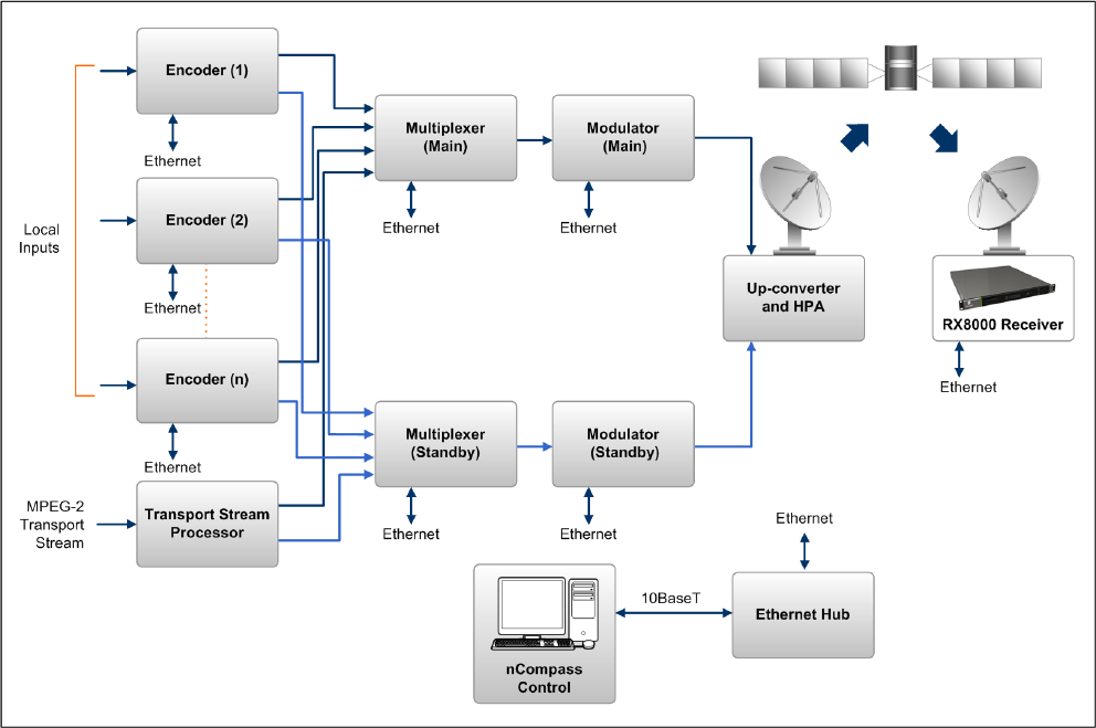
The RX8000 Series Receiver is a component of the MPEG-4 AVC/ MPEG-2/DVB
compliant range of Ericsson equipment. They are designed for use by broadcasters
and distributors of video, audio and data Services over satellite.
Figure 1.1 Typical Satellite Compression System
1.3.2 Input Connections
The Satellite Receiver interfaces directly to a Low-Noise Block (LNB) and accepts
an intermediate frequency (IF) input in the band 950 - 2150 MHz (L-band) for
operation in the specified symbol-rate range (see Annex B, Technical Specification).
The unit can provide DC power and polarization switching to the LNB.
EN/LZT 790 0005 R1A
1-17
Chapter 1
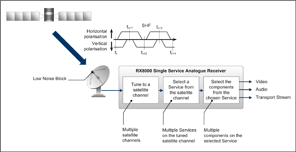
1.3.3 What the Satellite Receiver Does
The Receiver can be tuned to a specified satellite channel frequency and
polarization. The input is down-converted via a Low-Noise Block (LNB) to provide an
L-band input to the Receiver. The front-end tuning is microprocessor controlled with
a frequency synthesized local oscillator. A software tuning and acquisition algorithm
resolves translation errors (mainly due to the LNB).
The signal is then passed to a demodulator that recovers the signal using soft-
decision decoding. The resulting stream is Reed-Solomon decoded and
descrambled to provide inputs to the Decoder circuit. The received channel may
contain multiple Services, therefore the Receiver’s demultiplexer is configured to
select a single video Service and other audio/data components and present them at
the output.
Figure 1.2 What the Satellite Receiver Does
EN/LZT 790 0005 R1A
1-18
Chapter 1
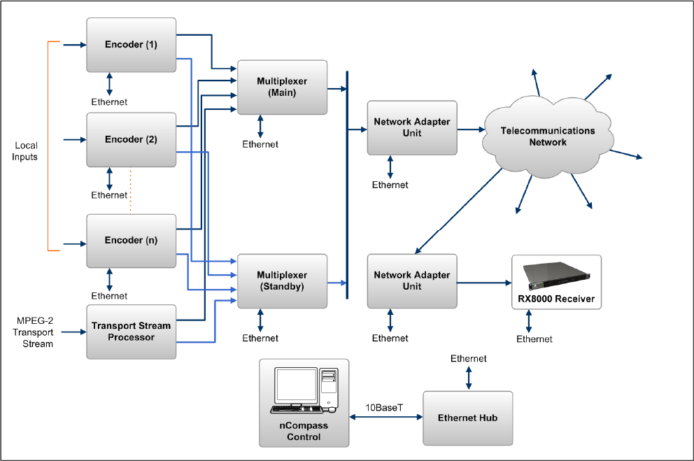
1.4 The Telco Receiver/Decoder
1.4.1 Typical Decoder System
The Decoder is a component of Ericsson range of equipment. It is designed for use
by broadcasters and distributors of video and audio Services. It can be used as a
Transport Stream monitor or to decode signals received over a telecommunications
network.
Figure 1.3 Typical Compression System
1.4.2 What the Decoder Does
The G.703, ASI or IP interface is used to present the Transport Stream in the format
required by the internal Decoder circuitry. At this point, the operation of the unit is
the same as the Satellite Receiver.
The Decoder can be used to receive an input signal from a Public Telecom Network
via a Network Adapter Unit (NAU) or directly via G.703. No error correction is
supported at the input of the unit so a level of Quality of Service should be
negotiated with the Telecom Network Provider.
EN/LZT 790 0005 R1A
1-19
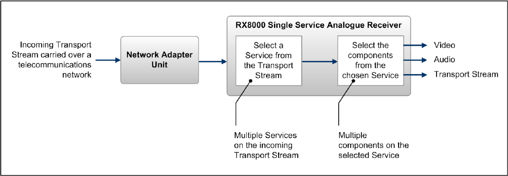
Chapter 1
The Decoder is configured to select a single video Service and other audio/data
components from the multiple Services on the incoming Transport Stream and
present them at the output.
Figure 1.4 Role of the Decoder
Note: G.703 input may also be used to interface to telco infrastructure.
1.5 Construction
The RX8000 Receiver is constructed using a screened self-ventilated modular
system. All operational inputs and outputs are via rear-panel connectors. The unit
may be operated freestanding or mounted in a 19-inch rack.
1.6 Front Panel
The user interface for the Front Panel consists of an alphanumeric Liquid Crystal
Display, pushbuttons, and a status LED that are used to set-up, control and monitor
the unit.
Various menu screens can be navigated on the LCD using the pushbuttons, which
allow you to select and modify key parameters and features of the unit.
Full details of the front panel menus and information on the use of these controls is
given in Chapter 3, Front Panel Control.
EN/LZT 790 0005 R1A
1-20

Chapter 1
EDIT
SAVE DOWN RIGHT
LEFT UP
LCD
USB Connector
(Servicing Only)
Status LED
CA SLOT
Figure 1.5 Front Panel Controls (RX8200)
Table 1.12 Front Panel Controls
Item Color Description
CA Slot - Conditional Access Slot. Located on front panel of
RX8200 and rear panel of RX8310, RX8315 and
RX8330.
USB Connector - This connector is for factory / service use only.
Red CRITICAL Error. Indicates that the unit has lost
lock with the Transport Stream.
Amber MAJOR or MINOR Error. Indicates that the unit is
locked to a Transport Stream but an error has
been detected signifying incorrect conditions or
system functioning.
Status LED
Green NO Errors. Indicates that the unit is locked to a
Transport Stream and correct conditions and
system functioning are detected.
LCD - 2-line x 40-character back-lit dot-matrix Liquid
Crystal Display (LCD).
Edit - This pushbutton enables you to edit the
parameters on the selected LCD menu. Press
again to exit without saving any changes. Integral
LED lit when functional.
Save - This pushbutton enables you to save any modified
parameters on the selected LCD menu. Integral
LED lit when functional.
S Up
T Down
W Left (Back)
X Right (Forward)
- Navigation pushbuttons for selecting relevant LCD
menu or for incrementing / decrementing selected
parameter values. Integral LED lit when
functional.
EN/LZT 790 0005 R1A
1-21
Chapter 1
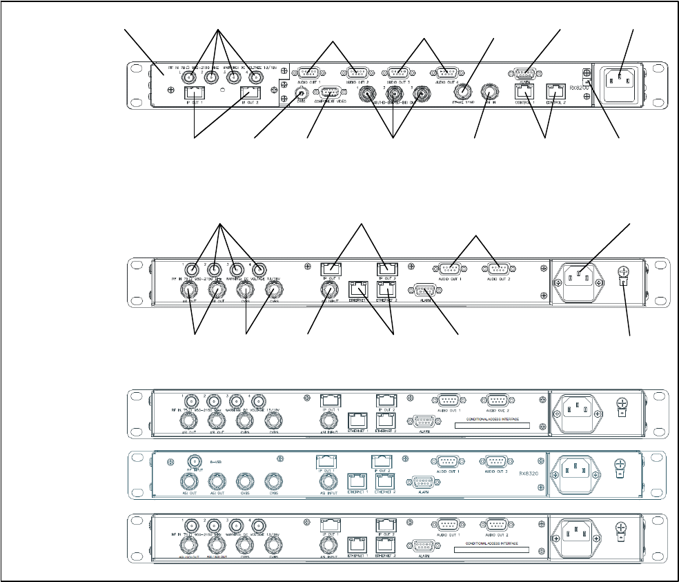
1.7 Rear Panels
All inputs, outputs and control connections are taken via the rear panel. Due to the
modular nature of these units, factory fitted hardware modules with different
connections can be fitted to any unit and therefore only a typical (sample) rear panel
images are shown below.
Full details of the connectors for ALL base models and options are given in
Chapter 2, Installing the Equipment.
Full details of all the options are given in Chapter 6, Options.
ASI/HD-SDI/SD-
SDI OUT 1-3
TECHNICAL
EARTH
AC POWER
IP OUT 1-2
RF IN 1-4
CVBS
ALARM
CONTROL
1-2
A
SI INPUT
RX8200
Sample configuration
with: Satellite input,
frame sync, HD video
output, IP Transport
Stream output and 2x
Audio output modules
installed.
RX8310
RX8315
RX8320
RX8330
AUDIO OUT (1)
1-2
INPUT MODULE AUDIO OUT (2)
3-4
COMPONENT
VIDEO
FRAME
SYNC
ETHERNET 1-2
TECHNICAL
EARTH
ASI OUT 1-2
CVBS
A
LARM ASI INPUT
AC POWER
RF IN 1-4 AUDIO OUT (1)
1-2
IP OUT 1-2
Figure 1.6 Rear Panels (RX8200, RX8310, RX8315, RX8320 and RX8330)
EN/LZT 790 0005 R1A
1-22

Chapter 1
Table 1.13 Rear Panels
Item Type Description
RF IN 1-4 F-type 75 Ω Radio Frequency (L-band) input.
ASI OUT 1-2
ASI/SDI OUT
ASI/HD-SDI/SD-SDI
OUT
BNC 75 Ω ASI = Asynchronous Serial Interface.
SDI = Synchronous Data Interface.
SD-SDI = Standard Definition SDI.
HS- SDI = High Definition SDI.
CVBS BNC 75 Ω Composite Video output.
ASI INPUT BNC 75 Ω Asynchronous Serial Interface input.
Streaming data format which carries the
MPEG Transport Stream.
SVGA OUTPUT 15-way D-type Component Video output (RGB/HV (SVGA) or
YPrPb).
IP OUT 1-2 RJ-45 IP Output card supports 1000BaseT Ethernet
transmission of encapsulated transport stream
ETHERNET 1-2
CONTROL 1-2
RJ-45 Gigabit IP data / feed output on dual redundant
connectors.
ALARM
ALARM RELAY
9-way D-type A summary ALARM relay provides contact
closure when the unit detects an alarm, or the
power is switched off.
AUDIO OUT 1-2 9-way D-type Each connector carries a single channel of a
stereo pair in both analogue and balanced
digital form.
CA INTERFACE Card Slot A single slot allows the insertion of a Smart
Card for the use of Common Interface Support.
AC POWER IEC 100-240 V AC power input.
TECHNICAL EARTH Spade
terminal
Unit earthing connector.
EN/LZT 790 0005 R1A
1-23
Chapter 1
EN/LZT 790 0005 R1A
1-24
BLANK

2 Installing the Equipment
Chapter 2
Contents
2.1 Read This First! ....................................................................................2-3
2.1.1 Handling ...............................................................................................2-3
2.1.2 Installing the Equipment .......................................................................2-3
2.1.3 Lifting .................................................................................................... 2-3
2.1.4 Site Requirements ................................................................................2-3
2.1.4.1 Power Supplies..................................................................................... 2-3
2.1.4.2 Environment .........................................................................................2-3
2.1.4.3 Lightning Protection..............................................................................2-3
2.2 Preliminary Checks............................................................................... 2-4
2.2.1 Mechanical Inspection .......................................................................... 2-4
2.2.2 Moving the Equipment Safely............................................................... 2-4
2.3 Installing the Equipment .......................................................................2-4
2.3.1 Fixing .................................................................................................... 2-4
2.3.2 Ventilation.............................................................................................2-5
2.3.2.1 Openings in the Covers ........................................................................2-5
2.3.2.2 Care in Positioning ...............................................................................2-5
2.3.2.3 Protection from Moisture ......................................................................2-5
2.3.3 Installing Cables - Safety......................................................................2-6
2.4 EMC Compliance Statements ..............................................................2-6
2.4.1 EN 55022/AS/NZS 3548....................................................................... 2-6
2.4.2 FCC ......................................................................................................2-6
2.5 AC Supply Operating Voltage and Fusing – Safety Information........... 2-6
2.5.1 AC Power Supply .................................................................................2-6
2.5.2 AC Power Supply Cord......................................................................... 2-7
2.5.2.1 General.................................................................................................2-7
2.5.2.2 Wire Colors...........................................................................................2-7
2.5.3 Connecting the Equipment to the AC Power Supply ............................2-8
2.6 Protective Earth/Technical Earth ..........................................................2-8
2.7 Signal Connections............................................................................... 2-9
2.7.1 General.................................................................................................2-9
2.7.2 RF IN Connector (RX8200 and RX8320 only)....................................2-10
2.7.3 ASI OUT Connector (RX8310/15/20 only)..........................................2-11
2.7.4 ASI/SDI OUT Connector (RX8200 and RX8330 only)........................ 2-12
2.7.5 ASI/HD-SDI/SD-SDI OUT Connector (RX8200 only) ......................... 2-12
2.7.6 CVBS Connector ................................................................................2-12
2.7.7 AUDIO/AUDIO OUT Connector..........................................................2-13
2.7.8 ETHERNET/CONTROL Connector .................................................... 2-13
EN/LZT 790 0005 R1A
2-1
Chapter 2
EN/LZT 790 0005 R1A
2-2
2.7.9 ASI IN Connector ............................................................................... 2-14
2.7.10 COMPONENT VIDEO Connector (RX8200 only) .............................. 2-14
2.7.11 DATA OUT Connector........................................................................ 2-15
2.7.12 ALARM Connector ............................................................................. 2-15
2.7.13 RS232/RS485 REMOTE Connector .................................................. 2-16
List of Figures
Figure 2.1 Air-Flow Through the Equipment.......................................................... 2-5
Figure 2.2 AC Power Inlet Assembly..................................................................... 2-7
Figure 2.3 Location of the Technical Earth on RX8200......................................... 2-9
Figure 2.4 Location of the Technical Earth on RX83XX........................................ 2-9
Figure 2.5 Rear Panels (RX8200, RX8310, RX8315, RX8320 and RX8330) ..... 2-10
List of Tables
Table 2.1 Supply Cord Wiring Colors................................................................... 2-8
Table 2.2 Non Standard Supply Cord Wire Colors............................................... 2-8
Table 2.3 RF IN Connector ................................................................................ 2-11
Table 2.4 ASI OUT Connector ........................................................................... 2-11
Table 2.5 ASI/SDI OUT Connector .................................................................... 2-12
Table 2.6 ASI/HD-SDI/SD-SDI OUT Connector................................................. 2-12
Table 2.7 CVBS Connector................................................................................ 2-12
Table 2.8 AUDIO/AUDIO OUT Connectors........................................................ 2-13
Table 2.9 ETHERNET/CONTROL Connectors.................................................. 2-13
Table 2.10 ASI IN Connector ............................................................................... 2-14
Table 2.11 COMPONENT VIDEO Connector ...................................................... 2-14
Table 2.12 DATA OUT Connector........................................................................ 2-15
Table 2.13 ALARM Connector ............................................................................. 2-15
Table 2.14 RS232/RS485 REMOTE Connector .................................................. 2-16

Chapter 2
2.1 Read This First!
2.1.1 Handling
The equipment must be handled and installed carefully and thoughtfully to prevent
safety hazards and damage.
2.1.2 Installing the Equipment
Ensure the personnel designated to fit the unit have the appropriate skills and
knowledge. If in any doubt, contact Ericsson Customer Services (see Preliminary
Pages for contact details).
Installation of the product should follow these instructions, and should only use
installation accessories recommended by the manufacturers. When rack mounted,
this equipment must have shelf supports as well as being fixed at the front panel.
Do not use this product as a support for any other equipment.
2.1.3 Lifting
In some circumstances the unit might be awkward to lift. In which case, do not
attempt to lift or move it without proper assistance or equipment. If in doubt, seek
assistance.
2.1.4 Site Requirements
2.1.4.1 Power Supplies
See Annex B, Technical Specification for a full specification.
2.1.4.2 Environment
See Annex B, Technical Specification for a full specification.
Do not install this product in areas of high humidity or where there is danger of water
ingress.
2.1.4.3 Lightning Protection
Warning!
If the receiver has been subject to a lightning strike or power surge which has
stopped it working, disconnect the power immediately. Do not re-apply power until it
has been checked for safety. If in doubt, contact Ericsson Customer Services.
EN/LZT 790 0005 R1A
2-3

Chapter 2
Where appropriate, ensure this product has an adequate level of lightning
protection. Alternatively, during a lightning storm or when it is left unattended and
unused for long periods of time, unplug it from the supply outlet and disconnect the
output equipment. This prevents damage to the product due to lightning and power
line surges.
2.2 Preliminary Checks
2.2.1 Mechanical Inspection
When taking delivery of a RX8000 Series Receiver check the equipment items
delivered against the enclosed delivery note. Inspect the equipment for damage in
transit. If in doubt, contact Ericsson Customer Services (see Preliminary Pages).
Note: Do not remove the covers of this equipment as doing so may invalidate any
warranties, cause a safety hazard and/or affect the EMC performance. It
may also invalidate any safety tests. Check with Ericsson Customer
Services beforehand.
2.2.2 Moving the Equipment Safely
Do not place this product on an unstable cart, stand, bracket, or
table. The product may fall, causing serious injury and serious
damage to the product. Use only with a cart, stand, bracket or
table recommended by Ericsson.
An appliance and cart combination should be moved with care. Quick stops,
excessive force, and uneven surfaces may cause the appliance and cart
combination to overturn. Do not move or carry the equipment whilst it is still
connected to the supply or other leads, is live, or is in operation.
2.3 Installing the Equipment
2.3.1 Fixing
The equipment is designed for fixed use only and has been shipped with fixing
brackets suitable for a standard 19-inch rack. When installed in a rack, it should be
secured using the fixing brackets. In addition, support shelves must be used to
reduce the weight on the brackets. Ensure it is firmly and safely located and it has
an adequate flow of free-air.
Slide the receiver onto the chassis supports and affix to the rack by means of an
M6 x 18 mm panhead screw in each corner.
A freestanding unit should be installed on a secure horizontal surface where it is
unlikely to be knocked or its connectors and leads disturbed.
EN/LZT 790 0005 R1A
2-4
Chapter 2
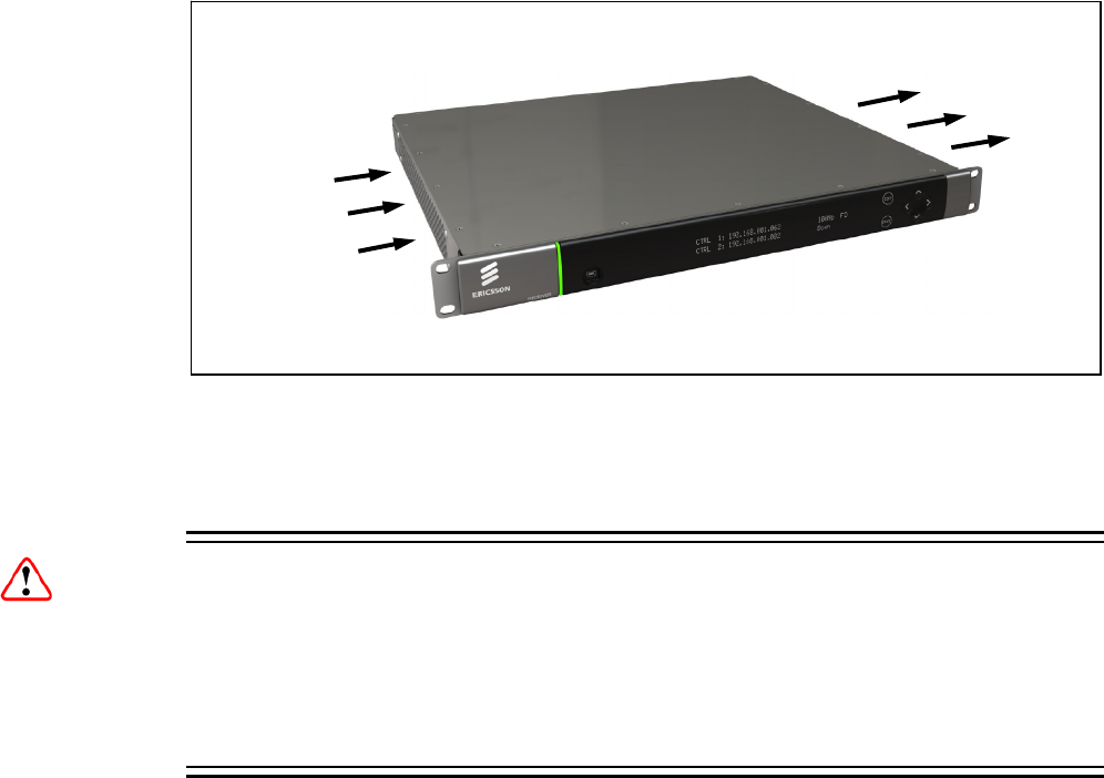
2.3.2 Ventilation
2.3.2.1 Openings in the Covers
Side openings in the unit, as well as side-mounted cooling fans, are provided for
ventilation. They ensure reliable operation of the product and protect it from
overheating. The openings of the fans must not be blocked or covered.
Figure 2.1 Air-Flow Through the Equipment
Air is released
through vents
at the side of
the unit.
Fans are
mounted on
this side of
the unit
2.3.2.2 Care in Positioning
Cautions!
The fans contained within this unit are not fitted with a dust/insect filter. Pay
attention to the environment in which it is to be used.
Do not install units so that the air intake of one aligns with the outlet on another.
Provide baffles and adequate spacing.
The equipment should never be placed near or over a radiator or other source of heat.
It should not be placed in a built-in installation such as a rack unless proper ventilation
is provided and the instructions have been adhered to.
Allow at least 40 mm free air-space at each side of the equipment to ensure
adequate cooling. Racks containing stacked equipment may need to be forced air-
cooled to reduce the ambient temperature within the rack.
2.3.2.3 Protection from Moisture
Do not install this equipment in areas of high humidity or where there is a danger of
water ingress.
EN/LZT 790 0005 R1A
2-5

Chapter 2
2.3.3 Installing Cables - Safety
Power supply cables should be routed so that they are not likely to be walked on or
pinched by items placed upon or against them. Pay particular attention to cables at
plugs, convenience receptacles, and the point where they exit from the appliance.
Do not run AC power cables in the same duct as signal leads. Do not move or install
equipment whilst it is still attached to the mains supply. Ensure safety and ESD
precautions are observed whilst inter-connecting equipment.
2.4 EMC Compliance Statements1
2.4.1 EN 55022/AS/NZS 3548
This is a Class A product. In a domestic environment this product may cause radio
interference in which case the User may be required to take adequate measures.
2.4.2 FCC
This equipment has been tested and found to comply with the limits for a Class A
digital device, pursuant to Part 15 of the FCC Rules. These limits are designed to
provide reasonable protection against harmful interference when the equipment is
operated in a commercial environment.
This equipment generates, uses and can radiate radio frequency energy and, if not
installed and used in accordance with the Reference Guide, may cause harmful
interference to radio communications. Operation of this equipment in a residential
area is likely to cause harmful interference in which case the User will be required to
correct the interference at ones own expense.
2.5 AC Supply Operating Voltage and Fusing – Safety
Information
2.5.1 AC Power Supply
The equipment operates from an wide-ranging mains power supply (100-240 V AC
50/60 Hz nominal) and is designed for use in ambient air temperature in the range
0°C to +50°C. There are no links etc. to be altered for operation from different
supply voltages. The full Technical Specification is given in Annex B, Technical
Specification.
1 The EMC information was correct at the time of manufacture.
EN/LZT 790 0005 R1A
2-6
Chapter 2
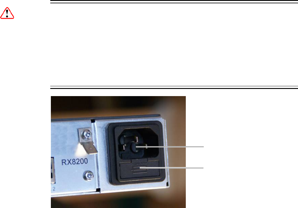
Warnings!
The RX8000 series receivers should only be operated from the type of power source
indicated on the marking label. If you are not sure of the type to your business,
consult your appliance dealer or local power company. Do not overload wall outlets
and extension cords as this can result in a risk of fire or electric shock.
The RX8000 series receivers are NOT fitted with an AC power ON/OFF switch.
Ensure the supply socket outlet is installed or located near the equipment so that it
is accessible.
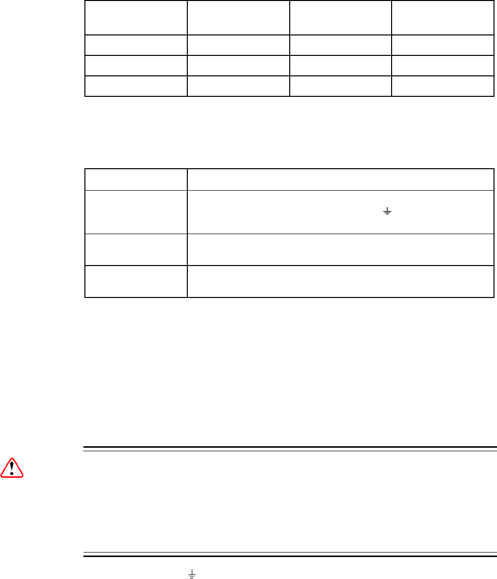
Figure 2.2 AC Power Inlet Assembly
Note: See Annex B, Technical Specification for fuse information.
Supply Mains Inlet
Fuse Carrier
2.5.2 AC Power Supply Cord
2.5.2.1 General
A two-meter mains supply cord is supplied with this product. It is fitted with a molded
plug suitable for the USA, UK or mainland Europe as advised at the time of ordering.
Note: The equipment is not fitted with an AC power supply ON/OFF switch.
Ensure the socket-outlet supplying the equipment is installed near the
equipment so that it is easily accessible.
2.5.2.2 Wire Colors
The wires in the supply cord are colored as shown in Table 2.1.
EN/LZT 790 0005 R1A
2-7
Chapter 2
Table 2.1 Supply Cord Wiring Colors
UK
(BS 1363)
EUROPE
(CEE 7/7)
USA
(NEMA 5-15P)
Earth: Green-and-yellow Green-and-yellow Green
Neutral: Blue Blue White
Live: Brown Brown Black
If the colors do not correspond with the colored markings identifying the terminals in
a locally supplied plug, proceed as in Annex B. The inclusion of Table 2.2 is for
reference.
Table 2.2 Non Standard Supply Cord Wire Colors
Wire Color (UK) Action
green-and-yellow ...must be connected to the terminal in the plug which is marked
with the letter E or the safety earth symbol or colored green or
green-and-yellow.
blue ...must be connected to the terminal in the plug which is marked
with the letter N or colored black.
brown ...must be connected to the terminal in the plug which is marked
with the letter L or colored red.
2.5.3 Connecting the Equipment to the AC Power Supply
As there is no mains power switch fitted to this unit, ensure the local AC power
supply is switched OFF before connecting the supply cord. Connect the mains lead
to the equipment and then to the local supply.
2.6 Protective Earth/Technical Earth
Warnings!
This unit must be correctly earthed through the molded plug supplied; if the local
mains supply does not have an earth conductor do not connect the unit. Contact
Ericsson Customer Services for advice.
Before connecting the unit to the supply, check the supply requirements in Annex B.
The terminal marked at the rear panel is a Technical Earth. Its use is
recommended. This is NOT a protective earth for electric shock protection. The
terminal is provided to:
1. Ensure all equipment chassis fixed within a rack are at the same technical earth
potential.
EN/LZT 790 0005 R1A
2-8
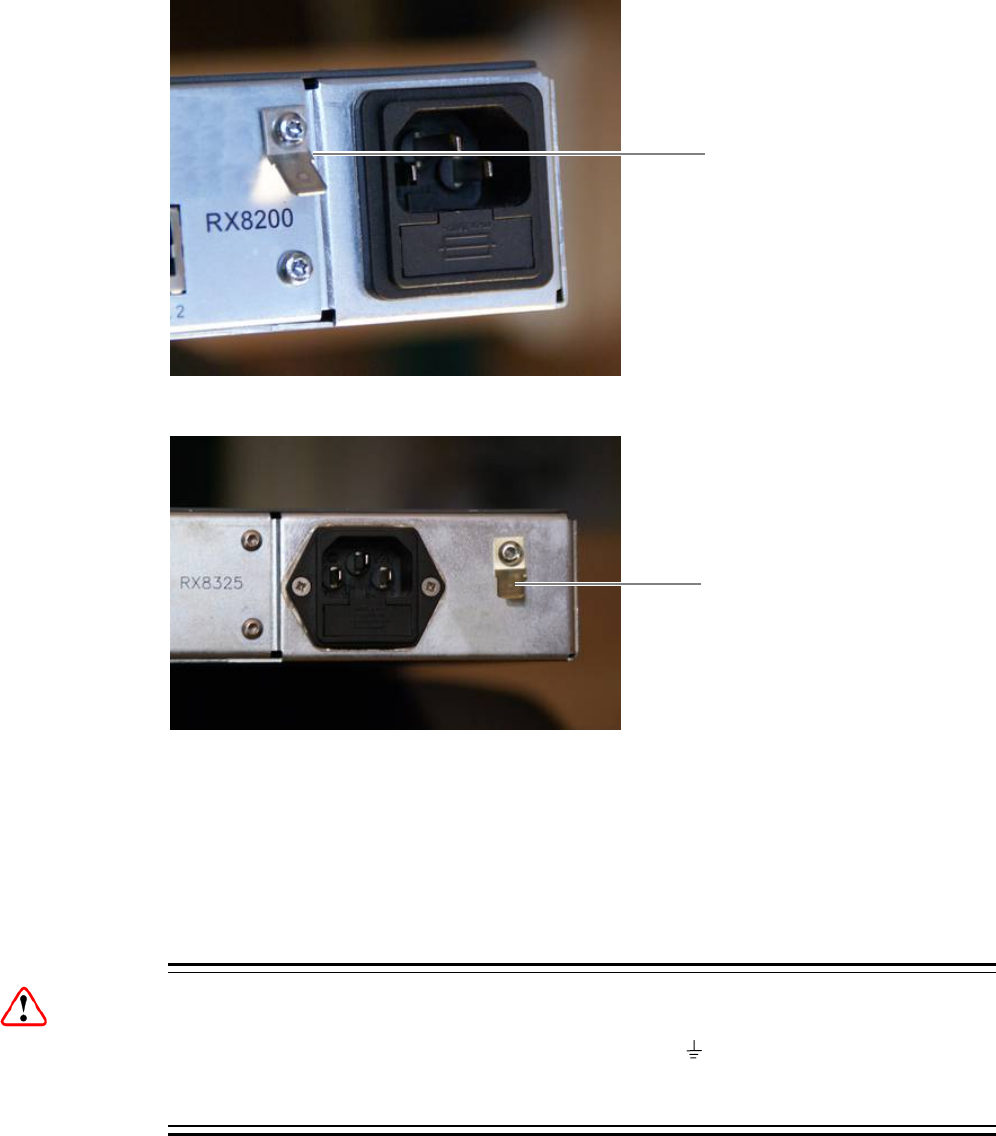
Chapter 2
2. Eliminate the migration of stray charges when connecting between equipment.
To do this, connect a wire between the Technical Earth terminal and a suitable
point on the rack.
The Technical Earth provides a suitable connection between the equipment and the
installation to give a low impedance path at normal operating frequencies.
Figure 2.3 Location of the Technical Earth on RX8200
Figure 2.4 Location of the Technical Earth on RX83XX
2.7 Signal Connections
2.7.1 General
Caution!
It is strongly recommended that the terminal marked at the rear panel of the
equipment is connected to a site Technical Earth before any external connections
are made and the equipment is powered. This limits the migration of stray charges.
Technical Earth
Technical Earth
EN/LZT 790 0005 R1A
2-9
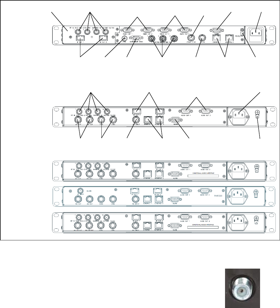
Chapter 2
All signal connections are made via the rear panel. A typical rear panel is shown in
Figure 2.5. Full technical specifications for the connections are given in Annex B.
The Receiver provides a flexible Transport Stream input interface. The status
information appropriate to each input type is available to the User via the User
Interface, and also via the remote control interfaces.
ASI/HD-SDI/SD-
SDI OUT 1-3
TECHNICAL
EARTH
AC POWER
IP OUT 1-2
RF IN 1-4
CVBS
ALARM
CONTROL
1-2
A
SI INPUT
RX8200
Sample configuration
with: Satellite input,
frame sync, HD video
output, IP Transport
Stream output and 2x
Audio output modules
installed.
RX8310
RX8315
RX8320
RX8330
AUDIO OUT (1)
1-2
INPUT MODULE AUDIO OUT (2)
3-4
COMPONENT
VIDEO
FRAME
SYNC
ETHERNET 1-2
TECHNICAL
EARTH
ASI OUT 1-2
CVBS
A
LARM ASI INPUT
AC POWER
RF IN 1-4 AUDIO OUT (1)
1-2
IP OUT 1-2
Figure 2.5 Rear Panels (RX8200, RX8310, RX8315, RX8320 and RX8330)
2.7.2 RF IN Connector (RX8200 and RX8320 only)
Up to four RF inputs connect the L-band output of a
suitable Low-Noise Block down-converter (LNB) to the
unit either directly or via a suitable attenuator.
The RF inputs may also be used to supply DC power to
the LNB, if required.
RF IN 1/2/3/4
EN/LZT 790 0005 R1A
2-10
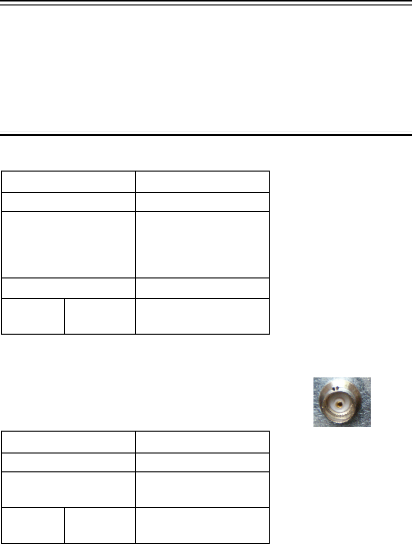
Chapter 2
Cautions!
The receiver provides DC power (see Chapter 3, Front Panel Control for details of
menu option) via the active L-band input connector to drive an LNB. Do not connect
equipment other than an LNB to this connector. Failure to do this may result in
damage to the external equipment.
The F-type connector is not suitable for repeated connection and disconnection.
When intended for use in this way, fit a sacrificial connector and connect to it.
Table 2.3 RF IN Connector
Item Specification
Connector type F-type 75 Ω female socket
Connector designation RF IN 1
RF IN 2
RF IN 3
RF IN 4
LNB Power Supply See Cautions! above.
Pin-outs Centre
Shield
Input
Ground/Chassis
2.7.3 ASI OUT Connector (RX8310/15/20 only)
The unit provides two coaxial ASI digital outputs
depending on the user selectable configuration.
Table 2.4 ASI OUT Connector
Item Specification
Connector type BNC 75 Ω female socket
Connector designation ASI OUT 1
ASI OUT 2
Pin-outs Centre
Shield
Output
Ground/Chassis
ASI OUT
EN/LZT 790 0005 R1A
2-11

Chapter 2
2.7.4 ASI/SDI OUT Connector (RX8200 and RX8330 only)
The unit provides two coaxial ASI/SDI outputs depending
on the user selectable configuration.
Table 2.5 ASI/SDI OUT Connector
Item Specification
Connector type BNC 75 Ω female socket
Connector designation ASI OUT 1
ASI OUT 2
Pin-outs Centre
Shield
Output
Ground/Chassis
ASI/SDI OUT
2.7.5 ASI/HD-SDI/SD-SDI OUT Connector (RX8200 only)
The unit provides three coaxial ASI/HD-SDI/SD-SDI
outputs depending on the user selectable configuration.
Table 2.6 ASI/HD-SDI/SD-SDI OUT Connector
Item Specification
Connector type BNC 75 Ω female socket
Connector designation ASI/HD-SDI/SD-SDI OUT 1
ASI/HD-SDI/SD-SDI OUT 2
ASI/HD-SDI/SD-SDI OUT 3
Pin-outs Centre
Shield
Output
Ground/Chassis
ASI/HD-SDI/SD-SDI OUT
2.7.6 CVBS Connector
A coaxial socket provides composite video outputs
supporting NTSC(M) (with and without pedestal) and
PAL(B,D,H,I,M).
Table 2.7 CVBS Connector CVBS
Item Specification
Connector type BNC 75 Ω female socket
Connector designation CVBS 1 (RX8200/RX300)
CVBS 2 (RX8300 only)
Pin-outs Centre
Shield
Output
Ground/Chassis
EN/LZT 790 0005 R1A
2-12
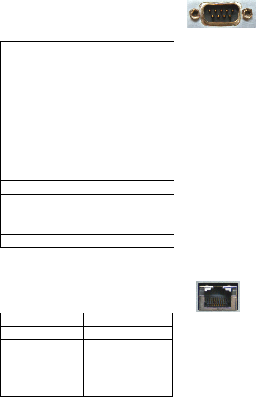
Chapter 2
2.7.7 AUDIO/AUDIO OUT Connector
All units provide a pair of connectors supplying two
stereo channels. Each carries a single channel stereo
pair in both analogue and balanced digital form.
Table 2.8 AUDIO/AUDIO OUT Connectors AUDIO/AUDIO OUT
Item Specification
Connector type 9-way, D-type, male
Connector designations AUDIO OUT 1
AUDIO OUT 2
AUDIO 3 (RX8200 only)
AUDIO 4 (RX8200 only)
Pin-outs Pin 1 – Digital audio +
Pin 2 – Ground
Pin 3 – Left +
Pin 4 – Right +
Pin 5 – Ground
Pin 6 – Digital audio –
Pin 7 – Ground
Pin 8 – Left –
Pin 9 – Right –
Nominal output impedance 50 Ω
Maximum data rate 3.072 Mbps
Analogue Output level +20 dBm nominal clipping
level. Selectable in range 12
to +24 dBm.
Load impedance ≥600 Ω balanced
2.7.8 ETHERNET/CONTROL Connector
All units provide two Ethernet remote control interfaces
for Web Browser Control.
Table 2.9 ETHERNET/CONTROL Connectors
Item Specification
Connector type RJ-45 (100BaseT)
Connector designation ETHERNET 1 or CONTROL 1
ETHERNET 2 or CONTROL 2
Pin-outs
(Unused pins not
connected)
Pin 1 – Tx Out (+)
Pin 2 – Tx Out (-)
Pin 3 – Rx In (+)
Pin 6 – Rx In (-)
ETHERNET/CONTROL
EN/LZT 790 0005 R1A
2-13
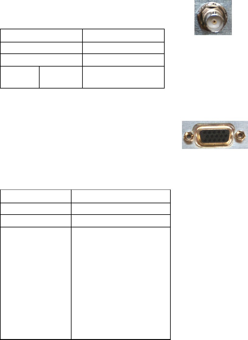
Chapter 2
2.7.9 ASI IN Connector
All units provide an ASI input socket for detection of the
transport stream lock on the ASI input.
Table 2.10 ASI IN Connector
Item Specification
Connector type BNC 75 Ω female socket
Connector designation ASI IN
Pin-outs Centre
Shield
Input
Ground/Chassis
ASI IN
2.7.10 COMPONENT VIDEO Connector (RX8200 only)
The equipment is equipped with a SVGA 15-pin D-type
connector for video output monitoring in the standard
configuration.
The SVGA connector shall be set to RGB/HV (SVGA) or
YPrPb under control of the User interface and remote
control interfaces.
Table 2.11 COMPONENT VIDEO Connector
COMPONENT VIDEO
Item Specification
Connector type 15-way D-type, female
Connector designation COMPONENT VIDEO
Pin-outs Pin 1 – Red / Pr, 75 Ω, 0,7Vt-t
Pin 2 – Green / Y, 75 Ω, 0,7Vt-t
Pin 3 – Blue / Pb, 75 Ω, 0,7Vt-t
Pin 4 – NC
Pin 5 – Video GND
Pin 6 – Red GND
Pin 7 – Green GND
Pin 8 – Blue GND
Pin 9 – NC
Pin 10 – Sync GND
Pin 11 – NC
Pin 12 – NC
Pin 13 – H-Sync
Pin 14 – V-Sync
Pin 15 – NC
EN/LZT 790 0005 R1A
2-14
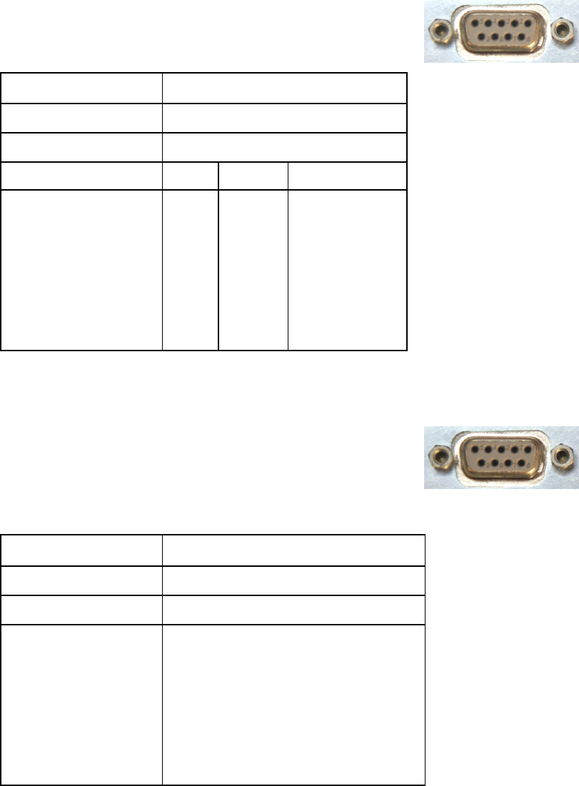
Chapter 2
2.7.11 DATA OUT Connector
A data output interface may be used with either RS232 or
RS422 connector, as described below.
Table 2.12 DATA OUT Connector
Item Specification
Connector type 9-way, D-type, female
Connector designation DATA OUT
Pin RS232 RS422
Pin-outs Pin 1
Pin 2
Pin 3
Pin 4
Pin 5
Pin 6
Pin 7
Pin 8
Pin 9
NC
TxD
RxD
NC
NC
NC
CTS
(RTS)
NC
HSD_CLK_A
NC
NC
NC
NC
HSD_CLK_B
NC
HSD_DATA_A
HSD_DATA_B
DATA OUT
2.7.12 ALARM Connector
All units provide an alarm relay connector supplying a
summary relay. Under user configuration, it is activated
whenever the unit detects an alarm, or the power is
switched off.
Table 2.13 ALARM Connector
ALARM RELAY
Item Specification
Connector type 9-way, D-type, female
Connector designation ALARM
Pin-outs Pin 1 – Relay 1, Normally Closed
Pin 2 – Relay 2, Common
Pin 3 – Relay 1, Common
Pin 4 – Relay 3, Common
Pin 5 – Relay 1, Normally Open
Pin 6 – Relay 2, Normally Closed
Pin 7 – Relay 2, Normally Open
Pin 8 – Relay 3, Normally Closed
Pin 9 – Relay 3, Normally Open
EN/LZT 790 0005 R1A
2-15

Chapter 2
EN/LZT 790 0005 R1A
2-16
2.7.13 RS232/RS485 REMOTE Connector
A remote control interface may be used with either RS232
or RS485 connector, as detailed below.
Table 2.14 RS232/RS485 REMOTE Connector
Item Specification
Connector type 9-way, D-type, male
Connector designation RS232/RS485 REMOTE
Pin RS232 RS485
Pin-outs Pin 1
Pin 2
Pin 3
Pin 4
Pin 5
Pin 6
Pin 7
Pin 8
Pin 9
DCD
RxD
TxD
DTR
Ground
DSR
RTS
CTS
RI
NC
NC
NC
RxD
NC
TxD-
TxD+
RXD-
NC
RS232/RS485 REMOTE

3 Front Panel Control
Chapter 3
Contents
3.1 Introduction...........................................................................................3-3
3.2 Powering the Equipment ......................................................................3-3
3.2.1 Switching On ........................................................................................3-3
3.2.2 Power Up Operating Modes .................................................................3-3
3.3 Using the Front Panel Controls ............................................................3-4
3.3.1 USB Connector..................................................................................... 3-5
3.3.2 Status LED ...........................................................................................3-5
3.3.3 LCD ......................................................................................................3-5
3.3.4 Arrow Pushbuttons (Up, Down, Left, Right)..........................................3-6
3.3.5 Edit and Save Pushbuttons ..................................................................3-6
3.4 Example Configuration .........................................................................3-7
3.5 Front Panel Menus ...............................................................................3-8
3.5.1 1 System............................................................................................. 3-10
3.5.1.1 1.1 Network ........................................................................................3-10
3.5.1.2 1.2 Build..............................................................................................3-12
3.5.1.3 1.3 USN .............................................................................................. 3-14
3.5.1.4 1.4 Factory..........................................................................................3-14
3.5.1.5 1.5 Front Panel (FP) ........................................................................... 3-15
3.5.2 2 Input (Satellite Input Card RX8200/HWO/DVBS2) ..........................3-16
3.5.2.1 2.1 Select/Primary Input .....................................................................3-16
3.5.2.2 2.2 Select Satellite Input.....................................................................3-17
3.5.3 2 Input (I/P Input Card RX8XXX/HWO/IP/GIGE)................................ 3-22
3.5.3.1 2.1 Select/Primary Input .....................................................................3-22
3.5.3.2 2.2 IP Input Card ................................................................................3-23
3.5.4 2 Input (8VSB Input Card RX8320/HWO/8VSB) ................................3-38
3.5.4.1 2.1 Select/Primary Input .....................................................................3-38
3.5.4.2 2.2 8VSB ............................................................................................3-39
3.5.4.3 2.3 8VSB CTRL .................................................................................. 3-39
3.5.5 2 Input (G703 ATM Input Card RX8XXX/HWO/G703) .......................3-40
3.5.5.1 2.1 Select/Primary Input .....................................................................3-40
3.5.5.2 2.2 G703.............................................................................................3-41
3.5.6 3 Service............................................................................................. 3-47
3.5.6.1 3.1 Decode Service ............................................................................3-47
3.5.6.2 3.2 Video ............................................................................................3-48
3.5.6.3 3.3 Audio ............................................................................................3-50
3.5.6.4 3.4 SDI Embedding ............................................................................3-51
3.5.7 4 CA Systems..................................................................................... 3-52
EN/LZT 790 0005 R1A
3-1
Chapter 3
EN/LZT 790 0005 R1A
3-2
3.5.7.1 4.1 Service Table ............................................................................... 3-52
3.5.7.2 4.2 Director......................................................................................... 3-53
3.5.8 5 Output ............................................................................................. 3-56
3.5.8.1 5.1 Output Selection........................................................................... 3-56
3.5.8.2 5.2 TS Feed Selection........................................................................ 3-57
3.5.9 6 Presets ............................................................................................ 3-58
3.5.9.1 6.1 Preset State ................................................................................. 3-58
3.5.9.2 6.2 Select/Save Presets..................................................................... 3-58
List of Figures
Figure 3.1 Power Up Operating Mode................................................................... 3-4
Figure 3.2 Front Panel Controls (RX8200)............................................................ 3-5
Figure 3.3 Front Panel Menus............................................................................... 3-8
Figure 3.4 Input Card Front Panel Menus ............................................................. 3-9
List of Tables
Table 3.1 Setting Up the DVB-S2 Satellite Receiver............................................ 3-7
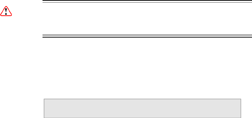
Chapter 3
3.1 Introduction
This chapter describes the features and options provided by the Front Panel menus
for controlling the RX8000 Series Receivers locally.
3.2 Powering the Equipment
3.2.1 Switching On
Caution!
This equipment should not be operated unless the cooling fans are working and
there is free-air flow around the unit.
1. Connect all signal and power cables to the rear panel of the unit. All connectors
are described in Chapter 2, Installing the Equipment.
2. Switch on the AC power supply to the unit at the wall or rack outlet.
Note: The RX8000 Series Receivers do NOT contain a power on/off switch.
3. After a short period of initialization the following screen is displayed on the Front
Panel:
INITIALIZING
4.3.2 (Bank 0)
4. During initialization, confirm that the Status LED is on and all Up, Down, Left,
Right, Edit and Save pushbuttons are lit.
3.2.2 Power Up Operating Modes
When the equipment is switched on it will assume the control mode that was set
when the power was turned off. This could be either:
• Local Front Panel/Web Browser control
• Director NCP control.
See the following figure for an overview of the power up operating modes. he following figure for an overview of the power up operating modes.
EN/LZT 790 0005 R1A
3-3
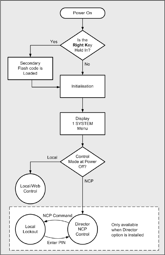
Chapter 3
Figure 3.1 Power Up Operating Mode
3.3 Using the Front Panel Controls
The user interface for the Front Panel consists of an alphanumeric Liquid Crystal
Display, pushbuttons, and a status LED that are used to set-up, control and monitor
the unit.
Various menu screens can be navigated on the LCD using the pushbuttons, which
allow you to select and modify key parameters and features of the unit.
EN/LZT 790 0005 R1A
3-4

Chapter 3
EDIT
SAVE DOWN RIGHT
LEFT UP
LCD
USB Connector
(Servicing Only)
Status LED
CA SLOT
Figure 3.2 Front Panel Controls (RX8200)
3.3.1 USB Connector
This connector is for factory / service use only.
3.3.2 Status LED
This multi-coloured LED provides a visual indication of the summary status of the
unit. The LED can be any one of three colours:
• Red (CRITICAL Error). Indicates that the unit has lost lock with the Transport
Stream.
• Amber (MAJOR or MINOR Error). Indicates that the unit is locked to a
Transport Stream but an error has been detected signifying incorrect conditions
or system functioning.
• Green (NO Errors). Indicates that the unit is locked to a Transport Stream and
correct conditions and system functioning are detected.
3.3.3 LCD
A 2-line x 40-character back-lit dot-matrix Liquid Crystal Display (LCD) displays
various menus and settings. The menus and setting available will vary depending on
which receiver model is being used and which options have been enabled through
the purchase of a suitable license.
See Front Panel Menus on page 3-8 for details of all menus.
All menu is numbered to aid with navigation and are arranged in 6 main categories:
1. System: This menu includes user settings for: IP Control ports set-up, IP Control
ports link status, Unit Build version details, Unit Electronic Serial Number.
2. Input: This menu is dependent on which Hardware Input Card Option is fitted to
the unit: Satellite Input Card, I/P Input Card, G.703 Input Card or 8VSB Input
Card.
EN/LZT 790 0005 R1A
3-5
Chapter 3
3. Service: This menu includes user settings for the currently selected service for
decode from the incoming feed.
4. CA Systems: This menu includes user settings for: the currently selected
services for decryption from the incoming feed, Director parameters and status.
5. Output: This menu includes user settings for: Output selection, TS Feed
Selection.
6. Presets: This menu includes user settings for storing and retrieving of up to
40 sets of input parameters (tuning parameters and service selections).
3.3.4 Arrow Pushbuttons (Up, Down, Left, Right)
Four arrow pushbuttons (or keys) are used to navigate through the front panel LCD
menus.
Each arrow pushbutton is backlit by an integral LED when active, indicating that a
further choice or action is available by pressing that pushbutton.
S = Up
T = Down
W = Left (Back)
X = Right (Forward)
3.3.5 Edit and Save Pushbuttons
The Edit and Save pushbuttons are used to modify and store user settings within
the selected menu.
The Edit pushbutton is backlit by an integral LED when the current menu contains
an editable setting.
To edit a user setting within the selected menu:
1. Press the Edit pushbutton and then use the W (Back) and X (Forward)
pushbuttons to move the cursor within that menu (if necessary).
2. Change the value of the setting using the S (Up) and T (Down) pushbuttons.
During this edit operation, both the Edit and Save pushbuttons will be lit.
The Save pushbutton is backlit by an integral LED when changes have been made
to a setting that require saving.
When a user setting has been modified:
1. Press the Save pushbutton to confirm and action this new setting.
EN/LZT 790 0005 R1A
3-6

Chapter 3
2. To ignore any changes that have been made and to return to the original setting,
press the Edit pushbutton.
3.4 Example Configuration
The following example configuration uses the Front Panel menus to set up the
DVB-S2 Satellite Receiver (not available for RX8320) using Menu 2.
Table 3.1 Setting Up the DVB-S2 Satellite Receiver
Step Action Result
1 Go to Menu 2.2 and select RF INPUT 1. The Receiver can take its signals from four sources.
Set-up source 1.
2 Scroll to Menu 2.2.2.1.1. Enter the LNB
FREQUENCY then press Save.
This sets up the LNB frequency for the selected
Source in MHz.
3 Scroll to Menu 2.2.2.1.2. Enter the
SATELLITE FREQUENCY then press
Save.
This sets up the Satellite frequency for the selected
Source in MHz.
4 Scroll to Menu 2.2.2.1.3. Enter the
SYMBOL RATE then press Save.
Sets the symbol rate for the selected Source in
Msymbol/s.
5 Scroll to Menu 2.2.2.1.4. Enter the DVB
Modulation Standard then press Save.
This sets up the DVB modulation Standard (DVB-S
or DVB-S2). FEC detection is automatic. In DVB-S2
mode the demodulator automatically detects and
locks to both QPSK and 8PSK constellations.
6 Scroll to Menu 2.2.2.1.5. Enter the
ROLL-OFF then press Save.
Sets the Roll-Off of the demodulator Root Nyquist
Filter. Choose between 35%, 25%, 20%. This value
should match that set in the transmitting modulator.
7 Scroll to Menu 2.2.2.1.7. Enter the
SEARCH RANGE then press Save.
This sets up the centre frequency Search Range for
the selected Source in kHz.
8 Scroll to Menu 2.2.2.1.8. and 2.2.2.1.9.
Enter the LNB POWER and VOLTAGE
settings then press Save.
Sets the LNB power for the selected Source
(ON, OFF). Also sets the LNB voltage settings
(18 V – Horiz, 13 V – Vert).
9 Scroll to Menu 2.2.2.1.10. Enter the LNB
22 kHz setting then press Save.
Enables or disables the LNB 22 kHz control tone for
the selected Source (On, Off).
10 Repeat steps 2 through 9 for input 2 to 4
EN/LZT 790 0005 R1A
3-7
Chapter 3
3.5 Front Panel Menus
An overview of the available Front Panel menus is shown in Figure 3.3. The menus
and settings available will vary depending on which receiver model is being used
and which options have been enabled through the purchase of a suitable license.
Boot Screen
— 1.1.1 IP1
— 1.1.2 MAC1
— 1.1.3 IP2
— 1.1.4 MAC2
— 1.1.5 Gateway
— 1.1.6 Status
— 1.4.1 Reset All Exc IP & Reboot
— 1.4.2 Reset All Incl IP & Reboot
— 1.1 Network Menu
— 1.2 Build Menu
— 1.3 Unit Serial Number
— 1.4 Factory Menu
— 1.5 FP (Front Panel) Menu
1. System Menu
Section 3.5.1
— 2.1 Select/Primary Input
— 2.2
— 1.5.1 Front Panel Lockout
— 3.1 Decode Service
3.1.1 Service I
— 3.2 Video
3.2.1 Component Selection
3.2.2 User PID
3.2.3 User STD
3.2.4 Delay Mode
3.2.5 Rx Delay
— 3.3 Audio
3.3.1 Audio 1
3.3.1.1 Component Selection
3.3.1.2 User PID
3.3.2-6 Audio 2-6 (as Audio 1)
3.4 SDI Embedding
3.4.1 CH 1+2: Embedding
3.4.2-3.4.8 CH3-16 Embedding (as CH 1+2)
— 4.1 Service Table
4.1.1 CA Summary
4.1.1.1 Service ID
4.1.1.2 - 4.1.1.24 Service ID Slots 2-24
— 4.2 Director V5
— 4.2.1 Over Air Message
— 4.2.2 Broadcaster ID
— 4.2.3 Unique Hardware ID
— 4.2.4 Manuf ID
— 4.2.5 Download Status
— 4.2.6 Enter New Pin
— 4.2.7 Reset Pin
— 4.2.8 Over Air Ext Carrier T/O
— 4.2.9 Over Air Control
— 4.2.10 Power Up Carrier
— 4.2.11 Emerg. Home Carrier
— 5.1 Output Selection
5.1.1 Outputs 1 and 2
5.1.2 Output 3
— 5.2 TS Feed Selection
— 6.1 Preset State
6.1.1 Preset 1 and 2
6.1.2-6.1.20 Presets 3-40
— 6.2 Select/Save Preset
— 1.2.1 SW Version
— 1.2.2 PS Version
— 1.2.3 SD FPGA Version
— 1.2.4 HD FPGA Version
— 1.2.5 Audio DSP Version
— 1.2.6 TS FPGA Version
— 1.2.7 HW ID
— 1.2.8 422 FW
— 1.2.9 422 SW
SWITCH ON
INITIALIZING
4.3.2 (Bank 0)
2. Input Menu
Section 3.5.2
3. Service Menu
Section 3.5.6
4. CA Systems
Section 3.5.7
5. Output
Section 3.5.8
6. Presets
Section 3.5.9
1.1 Network Menu
Section 3.5.1.1
1.2 Build Menu
Section 3.5.1.2
1.4 Factor y Menu
Section 3.5.1.4
1.5 FP (Front Panel) Menu
Section 3.5.1.5
4.2 Director Menu
Section 3.5.7.2
See Figure 3.4
for Input Menus
Figure 3.3 Front Panel Menus
EN/LZT 790 0005 R1A
3-8

Chapter 3
— 2.2.1 Status
2.2.1.1 Lock Status
2.2.1.2 Error Ratio/Signal Level
2.2.1.3 Modulation/FEC Rate
2.2.1.4 Standard/Spectral Sense
2.2.1.5 Pilot Symbols/Frame Size
— 2.2.2 Source 1 Configure
2.2.2.1 LNB Lo Frequency
2.2.2.2 Satellite Frequency
2.2.2.3 Symbol Rate
2.2.2.4 Modulation
2.2.2.5 Rolloff
2.2.2.6 Spectrum Sense
2.2.2.7 Search Range
2.2.2.8 LNB Power Op
2.2.2.9 LNB Power level
2.2.2.10 LNB 22kHz
— 2.2.3 Source 2 Configure
2.2.3.1-2.2.3.10 (as Source 1)
— 2.2.4 Source 3 Configure
2.2.4.1-2.2.4.10 (as Source 1)
— 2.2.5 Source 4 Configure
2.2.5.1-2.2.5.10 (as Source 1)
— 2.2.1 Status
2.2.1.1 Current Port
2.2.1.2 Encapsulation
2.2.1.3 Number of Columns/Rows
2.2.1.4 IP Packets Received
2.2.1.5 Corrected Packet Count
2.2.1.6 Lost Packet Count
2.2.1.7 Current Buffer Level
2.2.1.8 IP Jitter
2.2.1.9 TS Packets Per UDP Frm
2.2.1.10 FIFO Overflow Count
2.2.1.11 MDI Delay Factor
2.2.1.12 MDI Media Loss Rate
2.2.1.13 FEC Latency
2.2.1.14 Clear Statistics
— 2.2.2 Network 1 IP Address
2.2.2.1 Subnet Mask 1
2.2.2.2 Default Gateway 1
2.2.2.3 MAC Address 1
2.2.2.4 Ethernet Line Mode 1
2.2.2.5 Current Line Mode 1
2.2.2.6 RX Up Time 1
2.2.2.7 Network Utilisation 1
2.2.2.8 ICMP Enable 1
2.2.2.9 VLAN Enable 1
2.2.2.10 VLAN Tag 1
2.2.2.11 ARP Enable 1
2.2.2.12 Port 1 IGMP Version
2.2.2.13 Clear ARP 1
— 2.2.3 Network 2
2.2.3.1-2.2.3.13 (as Network 1)
— 2.2.4 Setup /MAC Mode
2.2.4.1 De-Jitter Buffer Level
2.2.4.2 SNMP Enable
2.2.4.3 FEC Enable
2.2.4.4 Network Util 1
2.2.4.5 Network Util 2
2.2.4.6 MDI Delay Factor
2.2.4.7 MDI Media Loss Rate
— 2.2.5 I/P Ports/ Use Input Ports
2.2.5.1 Auto Revert Delay
— 2.2.6 Stream 1/Unicast Enable 1
2.2.6.1 MCAST IP Address 1
2.2.6.2 Source IP Address 1
2.2.6.3 UDP Port 1
2.2.6.4 Column Port 1
2.2.6.5 Row Port 1
— 2.2.7 Stream 2/Unicast Enable 2
2.2.7.1 – 2.2.7.5 (as Stream 1)
— 2.2.8 Alarms/Alerts
2.2.8.1 Both Ports Lk Dn/No Data
2.2.8.2 Port 1/2 Link Down
2.2.8.3 Port 1/2 IP Conflict
2.2.8.4 Port 1/2 No Data
2.2.8.5 No Response/Out of Sync
2.2.8.6 Port 1/2 Net Util
2.2.8.7 MDI Dly Factor/Loss Rate
— 2.2.9 Version
2.2.9.1 Firmware SW Version
2.2.9.2 CPLD SW Version
2.2 I/P Input Card
Section 3.5.3
— 2.2.1 Status
2.2.1.1 Card Alarm Status
2.2.1.2 Physical Alert Status
2.2.1.3 MPEG Alert Status
2.2.1.4 ATM Alert Status
2.2.1.5 PDH Rate/Framing
2.2.1.6 Randomizer/Stuffing Pkts
2.2.1.7 TS Packet Length
— 2.2.2 Setup
2.2.2.1 Mode
2.2.2.2 Destuffing/ Deinterleaver
2.2.2.3 Reed-Solomon/
Derandomizer
2.2.2.4 Man Pkt Length Ctrl/
Packet Length Size
2.2.2.5 ATM Delta/ATM Alpha
2.2.2.6 ATM Descrambling/
ATM Header Correction
2.2.2.7 ATM Header Err Ignore/
ATM VPI
2.2.2.8 Sync Cnt to Lock/
Sync Miss Sample Size
2.2.2.9 Sync Miss Limit
2.2 Configure G.703 Input
Section 3.5.5
2.2 Select Satellite Input
Section 3.5.2
— 2.3 8VSB CTRL
2.2 8V SB Input
Section 3.5.4
Figure 3.4 Input Card Front Panel Menus
EN/LZT 790 0005 R1A
3-9

Chapter 3
3.5.1 1 System
Shortly after switch-on, the Status LED will turn green and arrow keys will be lit
depending on which further menus are available. The following System menu
screen is displayed:
SYSTEM |SYSTEM
1 | >
The functions within the System menu are used to set various network parameters,
IP and MAC addresses and to view Build, Unit Serial Number and Factory
parameter information.
3.5.1.1 1.1 Network
To access the Network menu from the System menu, press the X (Forward) key.
The following screen is displayed:
NETWORK |Network Settings
1.1 |IP, Subnet, MAC >
3.5.1.1.1 1.1.1 IP1
To access and edit the IP1 menu, press the X (Forward) key. The following screen
is displayed and the Edit key is lit:
IP1 |IP: 169.254.245.077
1.1.1 |Subnet: 255.255.000.000
To edit the IP address:
1. Press the Edit key. The cursor appears below the first character of the IP
address.
2. Edit the address as required using the W (Back) and X (Forward) keys to select
each digit in turn, and then using the S (Up) and T (Down) keys to increment or
decrement the digit.
3. Press Save to save the new settings or Edit to abandon the operation and
return to the current setting.
To edit the Subnet address:
1. Press the Edit key if not already in Edit mode. The cursor appears below the
first character of the IP address.
2. Press the X (Forward) key repeatedly to move the cursor to the end of the IP
address and down on to the Subnet address.
3. Edit the address as required using the W (Back) and X (Forward) keys to select
each digit in turn, and then using the S (Up) and T (Down) keys to increment or
decrement the digit.
EN/LZT 790 0005 R1A
3-10

Chapter 3
4. Press Save to save the new settings or Edit to abandon the operation and
return to the current setting.
3.5.1.1.2 1.1.2 MAC1
To access the MAC1 menu, press the T (Down) key. The following screen is
displayed:
MAC1 |MAC#1
1.1.2 |00:20:AA:55:05:9C
To edit the MAC1 address:
1. Press the Edit key. The cursor appears below the first character of the MAC
address.
2. Edit the address as required using the W (Back) and X (Forward) keys to select
each digit in turn, and then using the S (Up) and T (Down) keys to increment or
decrement the digit.
3. Press Save to save the new settings or Edit to abandon the operation and
return to the current setting.
3.5.1.1.3 1.1.3 IP2
To access and edit the IP2 menu, press the T (Down) key. The following screen is
displayed and the Edit key is lit:
IP2 |IP: 172.017.125.001
1.1.3 |Subnet: 255.255.000.000
To edit the IP2 IP and Subnet addresses, proceed as for IP1 above.
3.5.1.1.4 1.1.4 MAC2
To access the MAC2 menu, press the T (Down) key. The following screen is
displayed:
MAC2 |MAC#1
1.1.4 |00:20:AA:55:05:9C
To edit the MAC2 address, proceed as for MAC1 above.
3.5.1.1.5 1.1.5 Gateway
To access the Gateway menu, press the T (Down) key. The following screen is
displayed and the Edit key is lit:
GATEWAY |GATEWAY
1.1.5 |192.168.002.001
EN/LZT 790 0005 R1A
3-11

Chapter 3
To edit the Gateway address:
1. Press the Edit key. The cursor appears below the first character of the Gateway
address.
2. Edit the address as required using the W (Back) and X (Forward) keys to select
each digit in turn, and then using the S (Up) and T (Down) keys to increment or
decrement the digit.
3. Press Save to save the new settings or Edit to abandon the operation and
return to the current setting.
3.5.1.1.6 1.1.6 Status
This menu displays the status of the IP control interfaces. To access the Status
menu, press the T (Down) key. The following screen is displayed:
STATUS |CTRL 1 LINK STATUS Down
1.1.6 |CTRL 2 LINK STATUS Down
When Status menu details have been viewed, press the W (Back) key to return to
the Network sub-menu.
3.5.1.2 1.2 Build
The Build menu allows the viewing of all equipment SW, FW and HW Version
numbers. To access the Build menu, press the T (Down) key. The following screen
is displayed:
BUILD |Version
1.2 |SW, FW, HW
3.5.1.2.1 1.2.1 SW Version
To view the software (SW) version, press the X (Forward) key. The following screen
is displayed:
VERSIONS |SW VERSION
1.2.1 |4.3.2 (Bank 0)
3.5.1.2.2 1.2.2 PS Version
To view the PS version, press the T (Down) key. The following screen is displayed:
VERSIONS |PS VERSION
1.2.2 |0.14
EN/LZT 790 0005 R1A
3-12

Chapter 3
3.5.1.2.3 1.2.3 SD FPGA Version
To view the Standard Definition (SD) Field Programmable Gate Array (FPGA)
version, press the T (Down) key. The following screen (or a similar screen) is
displayed:
VERSIONS |SD FPGA VERSION
1.2.3 |0.2.5 [Built: Thu Apr 8 16:25:22 2010]
The bottom line scrolls to display the version details.
3.5.1.2.4 1.2.4 HD FPGA Version (RX8200 only)
To view the High Definition (HD) Field Programmable Gate Array (FPGA) version,
press the T (Down) key. The following screen (or a similar screen) is displayed:
VERSIONS |HD FPGA VERSION
1.2.4 |0.1.19 [Built: Wed Jun 16 08:32:13 2010]
The bottom line scrolls to display the version details.
3.5.1.2.5 1.2.5 Audio DSP Version (RX8200 only)
To view the Audio Digital Signal Processor (DSP) version, press the T (Down) key.
The following screen is displayed:
VERSIONS |AUDIO DSP VERSION
1.2.5 |0.2.8
3.5.1.2.6 1.2.6 TS FPGA Version (on RX8200 – Menu 1.2.4 on RX83XX)
To view the Transport Stream (TS) Field Programmable Gate Array (FPGA) version,
press the T (Down) key. The following screen is displayed:
VERSIONS |TS FPGA VERSION
1.2.6 |0.16.5 [Built: Mon Dec 14 09:20:26 2010]
The bottom line scrolls to display the version details.
3.5.1.2.7 1.2.7 HW ID
To view the Hardware (HW) Identifier (ID), press the T (Down) key. The following
screen is displayed:
VERSIONS |HW ID
1.2.7 |1.6.0
EN/LZT 790 0005 R1A
3-13

Chapter 3
3.5.1.2.8 1.2.8 422 FW (Option Card)
To view the 4:2:2 Firmware (FW) version (dependent on model and option licences
obtained), press the T (Down) key. The following screen is displayed:
VERSIONS |422 FW :---
1.2.8 |
3.5.1.2.9 1.2.9 422 SW (Option Card)
To view the 4:2:2 Software (SW) version (dependent on model and option licenses
obtained), press the T (Down) key. The following screen is displayed:
VERSIONS |422 SW :---
1.2.9 |
This is the last of the Version screens. To return to the Build menu, press the W
(Back) key.
3.5.1.3 1.3 USN
To view the Unit Serial Number (USN) of the equipment, press the T (Down) key.
The following screen is displayed:
USN |SERIAL NUMBER
1.3 |01436
3.5.1.4 1.4 Factory
The Factory menu allows the setting of equipment parameters to default values and
various equipment rebooting options. To access the Factory menu, press the T
(Down) key. The following screen is displayed:
FACTORY |Reset Params to Defaults
1.4 |incl/excl IP params & reboot >
3.5.1.4.1 1.4.1 Reset All Excl IP & Reboot
To access this function, press the X (Forward) key. The following screen is
displayed and the Edit key is lit:
FACTORY |RESET ALL EXCL IP & REBOOT
1.4.1 |NO
To enable/disable the reset excluding IP network parameters:
1. Press the Edit key. The cursor appears below the NO.
2. Use the S (Up) and T (Down) keys to toggle between YES and NO.
EN/LZT 790 0005 R1A
3-14

Chapter 3
3. Press Save to save the new settings or Edit to abandon the operation and
return to the current setting.
4. If YES is saved, inputs will be reset and the unit rebooted immediately.
3.5.1.4.2 1.4.2 Reset All Incl IP & Reboot
To access this function, press the T (Down) key. The following screen is displayed
and the Edit key is lit:
FACTORY |RESET ALL INCL IP & REBOOT
1.4.2 |NO
To enable/disable the reset including IP network parameters:
1. Press the Edit key. The cursor appears below the NO.
2. Use the S (Up) and T (Down) keys to toggle between YES and NO.
3. Press Save to save the new settings or Edit to abandon the operation and
return to the current setting.
4. If YES is saved, inputs will be reset and the unit rebooted immediately.
When all necessary operations have been performed, press the W (Back) key to
return to the Factory sub-menu.
3.5.1.5 1.5 Front Panel (FP)
To view the Lockout Front Panel (FP) Access menu, press the T (Down) key. The
following screen is displayed:
FP |LOCKOUT FRONT PANEL ACCESS
1.5 | >
3.5.1.5.1 1.5.1 Front Panel Lockout
To access the front panel lockout function, press the X (Forward) key.
Note: When enabled (set to ON) this function will disable the front panel controls
preventing further operation of any of the keys. The LCD will still continue to
display summary information screens. This feature may be disabled again
using the front panel controls.
The following screen is displayed:
FP |FRONT PANEL LOCKOUT
1.5.1 |OFF
To enable/disable front panel lockout:
1. Press the Edit key. The cursor appears below the OFF.
EN/LZT 790 0005 R1A
3-15

Chapter 3
2. Use the S (Up) and T (Down) keys to toggle between OFF and ON.
3. Press Save to save the new settings or Edit to abandon the operation and
return to the current setting.
To return to the System menu, press the W (Back) key twice.
3.5.2 2 Input (Satellite Input Card RX8200/HWO/DVBS2)
The Input menu is used to select the various inputs to the equipment and set input
parameters. To access the Input menu from the System menu, press the T (Down)
key. The following screen is displayed:
INPUT |UNLOCKED INPUT: ASI
2 |--- Mbits/s --- >
3.5.2.1 2.1 Select/Primary Input
To access this function, press the X (Forward) key. The following screen is
displayed:
INPUT |SELECT INPUT ASI
2.1 |PRIMARY INPUT ASI
The X (Forward) and W (Back) keys are used to choose the Select and Primary
input types.
To choose the Select input type:
1. Press the Edit key. The cursor appears below the displayed type (ASI shown
above).
2. Use the S (Up) and T (Down) keys to toggle between the available types: ASI,
SAT and AUTO (dependent on model and option licences obtained).
3. Press Save to save the new settings or Edit to abandon the operation and
return to the current setting.
To choose the Primary input:
1. Move to the Primary Input function using the X (Forward) key
2. Press the Edit key. The cursor appears below the displayed type (ASI shown
above).
3. Use the S (Up) and T (Down) keys to toggle between the available types: ASI
and SAT (dependent on model and option licences obtained).
4. Press Save to save the new settings or Edit to abandon the operation and
return to the current setting.
EN/LZT 790 0005 R1A
3-16

Chapter 3
3.5.2.2 2.2 Select Satellite Input
This menu allows the choice of up to four RF Inputs. To access this menu, press the
T (Down) key. The following screen is displayed:
S2 |SELECT SATELLITE INPUT
2.2 |RF Input 01 >
To select the relevant RF Input:
1. Press the Edit key. The cursor appears below the input number.
2. Use the S (Up) and T (Down) keys to toggle between input options 01-04
(dependent on model and option licences obtained).
3. Press Save to save the new settings or Edit to abandon the operation and
return to the current setting.
3.5.2.2.1 2.2.1 Status
To access the S2 Status menu, press the X (Forward) key. The following screen is
displayed:
S2 |STATUS
2.2.1 | >
3.5.2.2.1.1 2.2.1.1 Lock Status
To view the Status of the various equipment inputs, press the X (Forward) key. The
following screen is displayed:
STATUS |LOCK STATUS UNLOCKED
2.2.1.1 |C/N --- dB MARGIN --- dB
3.5.2.2.1.2 2.2.1.2 Status - Error Ratio/Signal Level
To view the status of these parameters, press the T (Down) key. The following
screen is displayed:
STATUS |ERROR RATIO ---
2.2.1.2 |SIGNAL LEVEL --- dBm
3.5.2.2.1.3 2.2.1.3 Status - Modulation/FEC Rate
To view the status of these parameters, press the T (Down) key. The following
screen is displayed:
STATUS |MODULATION ---
2.2.1.3 |FEC RATE -/--
EN/LZT 790 0005 R1A
3-17

Chapter 3
3.5.2.2.1.4 2.2.1.4 Standard/Spectral Sense
To view the status of these parameters, press the T (Down) key. The following
screen is displayed:
STATUS |STANDARD ---
2.2.1.4 |SPECTRAL SENSE ---
3.5.2.2.1.5 2.2.1.5 Pilot Symbols/Frame Size
To view the status of these parameters, press the T (Down) key. The following
screen is displayed:
STATUS |PILOT SYMBOLS ---
2.2.1.5 |FRAME SIZE ---
Press the W (Back) key to return to the S2 Status menu.
3.5.2.2.2 2.2.2 Source 1 Configure
This menu allows access to and configuration of various Source 1 Input 1
parameters. To access this function, press the T (Down) key. The following screen
is displayed:
SOURCE 1 |CONFIGURE Input 1 (L-band)
2.2.2 |(UNLOCKED) >
3.5.2.2.2.1 2.2.2.1 LNB LO Frequency
To view and edit the current settings of the Source 1 Low Noise Block (LNB) Local
Oscillator (LO) Frequency, press the X (Forward) key. The following screen is
displayed and the Edit key is lit:
SOURCE 1 |LNB LO FREQUENCY
2.2.2.1 |00000.000 MHz (UNLOCKED)
To edit the LNB LO frequency setting:
1. Press the Edit key. The cursor appears below the first number.
2. Edit the parameter value as required using the W (Back) and X (Forward) keys
to select each digit in turn, and then using the S (Up) and T (Down) keys to
increment or decrement the digit.
3. Press Save to save the new settings or Edit to abandon the operation and
return to the current setting.
3.5.2.2.2.2 2.2.2.2 Satellite Frequency
To view and edit the current settings of the Source 1 Satellite Frequency, press the
T (Down) key. The following screen is displayed and the Edit key is lit:
EN/LZT 790 0005 R1A
3-18

Chapter 3
SOURCE 1 |SATELLITE FREQUENCY
2.2.2.2 |01550.000 MHz (UNLOCKED)
To edit the frequency setting:
1. Press the Edit key. The cursor appears below the first number.
2. Edit the parameter value as required using the W (Back) and X (Forward) keys
to select each digit in turn, and then using the S (Up) and T (Down) keys to
increment or decrement the digit.
3. Press Save to save the new settings or Edit to abandon the operation and
return to the current setting.
3.5.2.2.2.3 2.2.2.3 Symbol Rate
To view and edit the current settings of the Source 1 Symbol Rate, press the T
(Down) key. The following screen is displayed and the Edit key is lit:
SOURCE 1 |SYMBOL RATE
2.2.2.3 |22.000000 MSym/s (UNLOCKED)
To edit the Symbol Rate setting:
1. Press the Edit key. The cursor appears below the first number.
2. Edit the parameter value as required using the W (Back) and X (Forward) keys
to select each digit in turn, and then using the S (Up) and T (Down) keys to
increment or decrement the digit.
3. Press Save to save the new settings or Edit to abandon the operation and
return to the current setting.
3.5.2.2.2.4 2.2.2.4 Modulation
To view and edit the current Source 1 Modulation settings, press the T (Down) key.
The following screen is displayed and the Edit key is lit:
SOURCE 1 |MODULATION
2.2.2.4 |DVB-S QPSK AUTO FEC (UNLOCKED)
To edit the Modulation setting:
1. Press the Edit key. The cursor appears below the first character.
2. Use the S (Up) and T (Down) keys to toggle between the available modulation
types (dependent on model and option licences obtained).
3. Press Save to save the new settings or Edit to abandon the operation and
return to the current setting.
EN/LZT 790 0005 R1A
3-19

Chapter 3
3.5.2.2.2.5 2.2.2.5 Rolloff
To view and edit the current Source 1 Rolloff settings, press the T (Down) key. The
following screen is displayed and the Edit key is lit:
SOURCE 1 |ROLLOFF
2.2.2.5 |20% (UNLOCKED)
To edit the Rolloff setting:
1. Press the Edit key. The cursor appears below the first character of the current
setting.
2. Use the S (Up) and T (Down) keys to toggle between the available percentage
settings.
3. Press Save to save the new settings or Edit to abandon the operation and
return to the current setting.
3.5.2.2.2.6 2.2.2.6 Spectrum Sense
To view and edit the current Source 1 Spectrum Sense settings, press the T
(Down) key. The following screen is displayed and the Edit key is lit:
SOURCE 1 |SPECTRUM SENSE
2.2.2.6 |AUTO (UNLOCKED)
To edit the Spectrum Sense setting:
1. Press the Edit key. The cursor appears below the first character of the current
setting.
2. Use the S (Up) and T (Down) keys to toggle between the available settings.
3. Press Save to save the new settings or Edit to abandon the operation and
return to the current setting.
3.5.2.2.2.7 2.2.2.7 Search Range
To view and edit the current Source 1 Search Range settings, press the T (Down)
key. The following screen is displayed and the Edit key is lit:
SOURCE 1 |SEARCH RANGE
2.2.2.7 |05000 KHz (UNLOCKED)
To edit the Search Range setting:
1. Press the Edit key. The cursor appears below the first character of the current
setting.
2. Edit the parameter value as required using the W (Back) and X (Forward) keys
to select each digit in turn, and then using the S (Up) and T (Down) keys to
increment or decrement the digit.
EN/LZT 790 0005 R1A
3-20

Chapter 3
3. Press Save to save the new settings or Edit to abandon the operation and
return to the current setting.
3.5.2.2.2.8 2.2.2.8 LNB Power OP
To view and edit the current Source 1 LNB power output settings, press the T
(Down) key. The following screen is displayed and the Edit key is lit:
SOURCE 1 |LNB POWER OP
2.2.2.8 |DISABLE (UNLOCKED)
To enable/disable the LNB Power Op:
1. Press the Edit key. The cursor appears below the first character of the current
setting.
2. Use the S (Up) and T (Down) keys to select ENABLE or DISABLE.
3. Press Save to save the new settings or Edit to abandon the operation and
return to the current setting.
3.5.2.2.2.9 2.2.2.9 LNB Power Level
To view and edit the current Source 1 LNB Power Level, press the T (Down) key.
The following screen is displayed and the Edit key is lit:
SOURCE 1 |LNB POWER LEVEL
2.2.2.9 |13V (VERT) (UNLOCKED)
To edit the LNB power level:
1. Press the Edit key. The cursor appears below the first character of the current
setting.
2. Use the S (Up) T (Down) keys to set the required value.
3. Press Save to save the new settings or Edit to abandon the operation and
return to the current setting.
3.5.2.2.2.10 2.2.2.10 LNB 22KHz
To enable or disable the Source 1 LNB 22KHz facility, press the T (Down) key. The
following screen is displayed and the Edit key is lit:
SOURCE 1 |LNB 22KHz
2.2.2.10 |ENABLE (UNLOCKED)
To enable/disable the LNB 22KHz facility:
1. Press the Edit key. The cursor appears below the first character of the current
setting.
2. Use the S (Up) T (Down) keys to select ENABLE or DISABLE.
EN/LZT 790 0005 R1A
3-21

Chapter 3
3. Press Save to save the new settings or Edit to abandon the operation and
return to the current setting.
This is the end of the Source 1 configure menu options. To return to the Source 1
menu press the W (Back) key.
3.5.2.2.3 2.2.3 – 2.2.5 Source 2/3/4 Configure
To access further Source menus from the Source 1 menu (dependent on model and
option licences obtained), press the T (Down) key.
The options for Source 2, 3 and 4 menus are as described for Source 1, see above.
To return to the input menu press the W (Back) key twice.
3.5.3 2 Input (I/P Input Card RX8XXX/HWO/IP/GIGE)
The Input menu is used to select the various inputs to the equipment and set input
parameters. To access the Input menu from the System menu, press the T (Down)
key. The following screen is displayed:
INPUT |UNLOCKED INPUT: ASI
2 |--- Mbits/s --- >
3.5.3.1 2.1 Select/Primary Input
To access this function, press the X (Forward) key. The following screen is
displayed:
INPUT |SELECT INPUT ASI
2.1 |PRIMARY INPUT ASI
The X (Forward) and W (Back) keys are used to choose the Select and Primary
input types.
To select the input type:
1. Press the Edit key. The cursor appears below the displayed type (ASI shown
above).
2. Use the S (Up) and T (Down) keys to toggle between the available types: ASI,
IP Input and AUTO (dependent on model and option licences obtained).
3. Press Save to save the new settings or Edit to abandon the operation and
return to the current setting.
To choose the Primary input:
1. Move to the Primary Input function using the X (Forward) key
2. Press the Edit key. The cursor appears below the displayed type (ASI shown
above).
EN/LZT 790 0005 R1A
3-22

Chapter 3
3. Use the S (Up) and T (Down) keys to toggle between the available types: ASI
and IP Input (dependent on model and option licences obtained).
4. Press Save to save the new settings or Edit to abandon the operation and
return to the current setting.
3.5.3.2 2.2 IP Input Card
This menu allows the viewing and editing of the IP Input Card parameters. To
access this menu, press the T (Down) key. The following screen is displayed:
IP I/P |IP Input Card
2.2 | >
3.5.3.2.1 2.2.1 Status
To access the Status menu for the I/P Card, press the X (Forward) key. The
following screen is displayed:
STATUS |LAST IP RECEIVED
2.2.1 |000.000.000.000 >
3.5.3.2.1.1 2.2.1.1 Current Port
To view the port, which is currently selected, press the X (Forward) key. The
following screen is displayed:
STATUS |CURRENT PORT (STATUS)
2.2.1.1 |Port 1
3.5.3.2.1.2 2.2.1.2 Encapsulation
To view the encapsulation status, press the T (Down) key. The following screen is
displayed:
STATUS |ENCAPSULATION
2.2.1.2 |UDP ONLY
3.5.3.2.1.3 2.2.1.3 Number of Columns/Rows
To view the number of columns and rows, press the T (Down) key. The following
screen is displayed:
STATUS |NUMBER OF COLUMNS N/A
2.2.1.3 |NUMBER OF ROWS N/A
3.5.3.2.1.4 2.2.1.4 IP Packets Received
To view the number of IP Packets received, press the T (Down) key. The following
screen is displayed:
EN/LZT 790 0005 R1A
3-23

Chapter 3
STATUS |IP PACKETS RECEIVED
2.2.1.4 |0000000000
3.5.3.2.1.5 2.2.1.5 Corrected Packet Count
To view the corrected packet count, press the T (Down) key. The following screen
is displayed:
STATUS |CORRECTED PACKET COUNT
2.2.1.5 |0000000000
3.5.3.2.1.6 2.2.1.6 Lost Packet Count
To view the lost packet count, press the T (Down) key. The following screen is
displayed:
STATUS |LOST PACKET COUNT
2.2.1.6 |0000000000
3.5.3.2.1.7 2.2.1.7 Current Buffer Level
To view the current buffer level, press the T (Down) key. The following screen is
displayed:
STATUS |CURRENT BUFFER LEVEL
2.2.1.7 |0 ms
3.5.3.2.1.8 2.2.1.8 IP Jitter
To view the IP jitter level, press the T (Down) key. The following screen is
displayed:
STATUS |IP JITTER
2.2.1.8 |0000000010
3.5.3.2.1.9 2.2.1.9 TS Packets per UDP Frame
To view the number of TS packets per UDP frame, press the T (Down) key. The
following screen is displayed:
STATUS |TS PACKETS PER UDP FRAME
2.2.1.9 |0000000007
3.5.3.2.1.10 2.2.1.10 FIFO Overflow Count
To view the FIFO overflow count, press the T (Down) key. The following screen is
displayed:
EN/LZT 790 0005 R1A
3-24

Chapter 3
STATUS |FIFO OVERFLOW COUNT
2.2.1.10 |0000000010
3.5.3.2.1.11 2.2.1.11 MDI Delay Factor
To view the MDI Delay Factor, press the T (Down) key. The following screen is
displayed:
STATUS |MDI DELAY FACTOR
2.2.1.11 |00.000
3.5.3.2.1.12 2.2.1.12 MDI Media Loss Rate
To view the MDI media loss rate, press the T (Down) key. The following screen is
displayed:
STATUS |MDI MEDIA LOSS RATE
2.2.1.12 |0 .000
3.5.3.2.1.13 2.2.1.13 FEC Latency
To view the FEC latency, press the T (Down) key. The following screen is
displayed:
STATUS |FEC LATENCY
2.2.1.13 |0 ms
3.5.3.2.1.14 2.2.1.14 Clear Statistics
To edit the clear statistics function, press the T (Down) key. The following screen is
displayed:
STATUS |CLEAR STATISTICS
2.2.1.14 |ACTIVATE
To activate/deactivate the Clear Statistics function:
1. Press the Edit key. The cursor appears below the function name.
2. Use the T (Down) key to show the ACTIVATE option
3. Press Save to save the new settings or Edit to abandon the operation and
return to the current setting.
To return to the Status menu press the W (Back) key.
3.5.3.2.2 2.2.2 Network 1 IP Address
To view and edit the Network 1 IP address, press the T (Down) key. The following
screen is displayed:
EN/LZT 790 0005 R1A
3-25

Chapter 3
NETWORK 1 |IP ADDRESS 1
2.2.2 |000.000.000.000 <
To edit the Network 1 IP address:
1. Press the Edit key. The cursor appears below the first character of the address.
2. Edit the parameter value as required using the W (Back) and X (Forward) keys
to select each digit in turn, and then using the S (Up) and T (Down) keys to
increment or decrement the digit.
3. Press Save to save the new settings or Edit to abandon the operation and
return to the current setting.
3.5.3.2.2.1 2.2.2.1 Subnet Mask 1
To view and edit the Subnet Mask 1 address, press the X (Forward) key. The
following screen is displayed:
NETWORK 1 |SUBNET MASK 1
2.2.2.1 |255.255.255.000
To edit the Subnet Mask 1 address:
1. Press the Edit key. The cursor appears below the first character of the address.
2. Edit the parameter value as required using the W (Back) and X (Forward) keys
to select each digit in turn, and then using the S (Up) and T (Down) keys to
increment or decrement the digit.
3. Press Save to save the new settings or Edit to abandon the operation and
return to the current setting.
3.5.3.2.2.2 2.2.2.2 Default Gateway 1
To view and edit the Default Gateway 1 address, press the T (Down) key. The
following screen is displayed:
NETWORK 1 |DEFAULT GATEWAY 1
2.2.2.2 |192.168.000.001
To edit the Default Gateway 1 address:
1. Press the Edit key. The cursor appears below the first character of the address.
2. Edit the parameter value as required using the W (Back) and X (Forward) keys
to select each digit in turn, and then using the S (Up) and T (Down) keys to
increment or decrement the digit.
3. Press Save to save the new settings or Edit to abandon the operation and
return to the current setting.
EN/LZT 790 0005 R1A
3-26

Chapter 3
3.5.3.2.2.3 2.2.2.3 MAC Address 1
To view the MAC Address 1, press the T (Down) key. The following screen is
displayed:
NETWORK 1 |MAC ADDRESS 1
2.2.2.3 |00:20:AA:4f:06:1b
3.5.3.2.2.4 2.2.2.4 Ethernet Line Mode 1
To view and edit the Ethernet Line Mode 1, press the T (Down) key. The following
screen is displayed:
NETWORK 1 |ETHERNET LINE MODE 1
2.2.2.4 |AUTO
To edit the Ethernet Line Mode 1:
1. Press the Edit key. The cursor appears below the first character of the displayed
option.
2. Use the S (Up) and T (Down) keys to toggle between the available options:
AUTO, 10 MBPS, 100MBPS or 1GBPS.
3. Press Save to save the new settings or Edit to abandon the operation and
return to the current setting.
3.5.3.2.2.5 2.2.2.5 Current Line Mode 1
To view the Current Line Mode 1, press the T (Down) key. The following screen is
displayed:
NETWORK 1 |CURRENT LINE MODE 1 Link Down
2.2.2.5 |DUPLEX 1 Link Down
3.5.3.2.2.6 2.2.2.6 RX Up Time 1
To view the RX Up Time 1, press the T (Down) key. The following screen is
displayed:
NETWORK 1 |RX UP TIME 1
2.2.2.6 |12668.54 sec
3.5.3.2.2.7 2.2.2.7 Network Utilisation 1
To view the Network Utilisation 1, press the T (Down) key. The following screen is
displayed:
NETWORK 1 |NETWORK UTILISATION 1
2.2.2.7 |000
EN/LZT 790 0005 R1A
3-27

Chapter 3
3.5.3.2.2.8 2.2.2.8 ICMP Enable 1
To view and edit the ICMP 1, press the T (Down) key. The following screen is
displayed:
NETWORK 1 |ICMP ENABLE 1
2.2.2.8 |Enable
To enable/disable the ICMP:
1. Press the Edit key. The cursor appears below the first character of the displayed
option.
2. Use the S (Up) and T (Down) keys to toggle between the Enable/Disable
options.
3. Press Save to save the new settings or Edit to abandon the operation and
return to the current setting.
3.5.3.2.2.9 2.2.2.9 VLAN Enable 1
To view and edit the VLAN 1, press the T (Down) key. The following screen is
displayed:
NETWORK 1 |VLAN ENABLE 1
2.2.2.9 |Disable
To enable/disable the VLAN:
1. Press the Edit key. The cursor appears below the first character of the displayed
option.
2. Use the S (Up) and T (Down) keys to toggle between the Enable/Disable
options.
3. Press Save to save the new settings or Edit to abandon the operation and
return to the current setting.
3.5.3.2.2.10 2.2.2.10 VLAN Tag 1
To view and edit the VLAN Tag 1, press the T (Down) key. The following screen is
displayed:
NETWORK 1 |VLAN TAG 1
2.2.2.10 |05500
To edit the VLAN Tag 1:
1. Press the Edit key. The cursor appears below the first character of the current
value.
EN/LZT 790 0005 R1A
3-28

Chapter 3
2. Edit the parameter value as required using the W (Back) and X (Forward) keys
to select each digit in turn, and then using the S (Up) and T (Down) keys to
increment or decrement the digit.
3. Press Save to save the new settings or Edit to abandon the operation and
return to the current setting.
3.5.3.2.2.11 2.2.2.11 ARP Enable 1
To view and edit the ARP 1, press the T (Down) key. The following screen is
displayed:
NETWORK 1 |ARP ENABLE 1
2.2.2.11 |Enable
To enable/disable the ARP:
1. Press the Edit key. The cursor appears below the first character of the displayed
option.
2. Use the S (Up) and T (Down) keys to toggle between the Enable/Disable
options.
3. Press Save to save the new settings or Edit to abandon the operation and
return to the current setting.
3.5.3.2.2.12 2.2.2.12 Port 1 IGMP Version
To view the Port 1 IGMP Version, press the T (Down) key. The following screen is
displayed:
NETWORK 1 |PORT 1 IGMP VERSION
2.2.2.12 |3
3.5.3.2.2.13 2.2.2.13 Clear ARP 1
To view and edit the ARP 1, press the T (Down) key. The following screen is
displayed:
NETWORK 1 |CLEAR ARP 1
2.2.2.13 |ACTIVATE
To activate/deactivate the ARP:
1. Press the Edit key. The cursor appears below the first character of the displayed
option.
2. Use the T (Down) key to show the ACTIVATE option.
3. Press Save to save the new settings or Edit to abandon the operation and
return to the current setting.
EN/LZT 790 0005 R1A
3-29

Chapter 3
This is the last of the Network 1 screens. To return to the top level Network 1 screen
press the W (Back) Key.
3.5.3.2.3 2.2.3 Network 2
From the Network 1 screen 2.2.2, press the T (Down) key. The following screen is
displayed.
NETWORK 2 |IP ADDRESS 2
2.2.3 |000.000.000.000 >
The Network address 2 may be edited and all of the Network 2 parameters viewed
and edited (where possible) as described in Section 3.5.3.2.2. When complete,
press the W (Back) Key to return to the top level Network 2 screen.
3.5.3.2.4 2.2.4 Setup/MAC Mode
To view and edit the MAC Mode, press the T (Down) key. The following screen is
displayed:
SETUP |MAC MODE
2.2.4 |Same >
To change the MAC Mode:
1. Press the Edit key. The cursor appears below the first character of the displayed
option.
2. Use the S (Up) and T (Down) keys to toggle between the Same and Different
options.
3. Press Save to save the new settings or Edit to abandon the operation and
return to the current setting.
3.5.3.2.4.1 2.2.4.1 De-Jitter Buffer Level
To view and edit the De-Jitter Buffer Level, press the X (Forward) key. The following
screen is displayed:
SETUP |DE-JITTER BUFFER LEVEL
2.2.4.1 |00500
To edit the De-Jitter Buffer Level:
1. Press the Edit key. The cursor appears below the first character of the displayed
option.
2. Edit the parameter value as required using the W (Back) and X (Forward) keys
to select each digit in turn, and then using the S (Up) and T (Down) keys to
increment or decrement the digit.
EN/LZT 790 0005 R1A
3-30

Chapter 3
3. Press Save to save the new settings or Edit to abandon the operation and
return to the current setting.
3.5.3.2.4.2 2.2.4.2 SNMP Enable
To view and edit the SNMP, press the T (Down) key. The following screen is
displayed:
SETUP |SNMP ENABLE
2.2.4.2 |Disable
To enable/disable the SNMP:
1. Press the Edit key. The cursor appears below the first character of the displayed
option.
2. Use the S (Up) and T (Down) keys to toggle between the Enable/Disable
options.
3. Press Save to save the new settings or Edit to abandon the operation and
return to the current setting.
3.5.3.2.4.3 2.2.4.3 FEC Enable
To view and edit the FEC, press the T (Down) key. The following screen is
displayed:
SETUP |FEC ENABLE
2.2.4.3 |Disable
To enable/disable the FEC:
1. Press the Edit key. The cursor appears below the first character of the displayed
option.
2. Use the S (Up) and T (Down) keys to toggle between the Enable/Disable
options.
3. Press Save to save the new settings or Edit to abandon the operation and
return to the current setting.
3.5.3.2.4.4 2.2.4.4 Network Util 1 (Max Value)
To view and edit the Network Util 1, press the T (Down) key. The following screen
is displayed:
SETUP |NETWORK UTIL 1 (MAX VALUE)
2.2.4.4 |100
To edit the Network Util 1:
1. Press the Edit key. The cursor appears below the first character of the displayed
option.
EN/LZT 790 0005 R1A
3-31

Chapter 3
2. Edit the parameter value as required using the W (Back) and X (Forward) keys
to select each digit in turn, and then using the S (Up) and T (Down) keys to
increment or decrement the digit.
3. Press Save to save the new settings or Edit to abandon the operation and
return to the current setting.
3.5.3.2.4.5 2.2.4.5 Network Util 2 (Max Value)
To view and edit the Network Util 2, press the T (Down) key. The following screen
is displayed:
SETUP |NETWORK UTIL 2 (MAX VALUE)
2.2.4.5 |100
To edit the Network Util 2:
1. Press the Edit key. The cursor appears below the first character of the displayed
option.
2. Edit the parameter value as required using the W (Back) and X (Forward) keys
to select each digit in turn, and then using the S (Up) and T (Down) keys to
increment or decrement the digit.
3. Press Save to save the new settings or Edit to abandon the operation and
return to the current setting.
3.5.3.2.4.6 2.2.4.6 MDI Delay Factor (Max Value)
To view and edit the MDI Delay Factor, press the T (Down) key. The following
screen is displayed:
SETUP |MDI DELAY FACTOR (MAX VALUE)
2.2.4.6 |50.000
To edit the MDI Delay Factor:
1. Press the Edit key. The cursor appears below the first character of the displayed
option.
2. Edit the parameter value as required using the W (Back) and X (Forward) keys
to select each digit in turn, and then using the S (Up) and T (Down) keys to
increment or decrement the digit.
3. Press Save to save the new settings or Edit to abandon the operation and
return to the current setting.
3.5.3.2.4.7 2.2.4.7 MDI Media Loss Rate (Max Value)
To view and edit the MDI Media Loss Rate, press the T (Down) key. The following
screen is displayed:
SETUP |MDI MEDIA LOSS RATE (MAX FACTOR)
EN/LZT 790 0005 R1A
3-32

Chapter 3
2.2.4.7 |0 .004
To edit the MDI Media Loss Rate:
1. Press the Edit key. The cursor appears below the first character of the displayed
option.
2. Edit the parameter value as required using the W (Back) and X (Forward) keys
to select each digit in turn, and then using the S (Up) and T (Down) keys to
increment or decrement the digit.
3. Press Save to save the new settings or Edit to abandon the operation and
return to the current setting.
This is the last of the Setup screens. To return to the top level Setup screen, press
the W (Back) key.
3.5.3.2.5 2.2.5 I/P Port/ Use Input Ports
To view and edit the I/P Input Port in use, press the T (Down) key. The following
screen is displayed:
I/P PORT |USE INPUT PORTS
2.2.5 |Port 1 >
To change the input port:
1. Press the Edit key. The cursor appears below the first character of the displayed
option.
2. Use the S (Up) and T (Down) keys to toggle between the Port 1, Port 2 and
Auto options.
3. Press Save to save the new settings or Edit to abandon the operation and
return to the current setting.
3.5.3.2.5.1 2.2.5.1 Auto Revert Delay
To view and edit the Auto Revert Delay, press the X (Forward) key. The following
screen is displayed:
I/P PORT |AUTO REVERT DELAY
2.2.5.1 |00000
To edit the Auto Revert Delay:
1. Press the Edit key. The cursor appears below the first character of the displayed
value.
2. Edit the parameter value as required using the W (Back) and X (Forward) keys
to select each digit in turn, and then using the S (Up) and T (Down) keys to
increment or decrement the digit.
EN/LZT 790 0005 R1A
3-33

Chapter 3
3. Press Save to save the new settings or Edit to abandon the operation and
return to the current setting.
This is the last of the I/P Port screens. To return to the top level I/P Port screen,
press the W (Back) key.
3.5.3.2.6 2.2.6 Stream 1/ Unicast Enable 1
To view and edit the Unicast Enable 1, press the T (Down) key. The following
screen is displayed:
STREAM 1 |UNICAST ENABLE 1
2.2.6 |TRUE >
To enable/disable the Unicast 1:
1. Press the Edit key. The cursor appears below the first character of the displayed
option.
2. Use the S (Up) and T (Down) keys to toggle between the True and False
options.
3. Press Save to save the new settings or Edit to abandon the operation and
return to the current setting.
3.5.3.2.6.1 2.2.6.1 MCAST IP Address 1
To view and edit the MCAST IP Address 1, press the X (Forward) key. The
following screen is displayed:
STREAM 1 |MCAST IP ADDRESS 1
2.2.6.1 |000.000.000.000
To edit the MCAST IP Address 1:
1. Press the Edit key. The cursor appears below the first character of the displayed
value.
2. Edit the parameter value as required using the W (Back) and X (Forward) keys
to select each digit in turn, and then using the S (Up) and T (Down) keys to
increment or decrement the digit.
3. Press Save to save the new settings or Edit to abandon the operation and
return to the current setting.
3.5.3.2.6.2 2.2.6.2 Source IP Address 1
To view and edit the Source IP Address 1, press the T (Down) key. The following
screen is displayed:
STREAM 1 |SOURCE IP ADDRESS 1
2.2.6.2 |000.000.000.000
EN/LZT 790 0005 R1A
3-34

Chapter 3
To edit the Source IP Address 1:
1. Press the Edit key. The cursor appears below the first character of the displayed
value.
2. Edit the parameter value as required using the W (Back) and X (Forward) keys
to select each digit in turn, and then using the S (Up) and T (Down) keys to
increment or decrement the digit.
3. Press Save to save the new settings or Edit to abandon the operation and
return to the current setting.
3.5.3.2.6.3 2.2.6.3 UDP Port 1
To view and edit the UDP Port 1, press the T (Down) key. The following screen is
displayed:
STREAM 1 |UDP PORT 1
2.2.6.3 |04000
To edit the UDP Port 1 value:
1. Press the Edit key. The cursor appears below the first character of the displayed
value.
2. Edit the parameter value as required using the W (Back) and X (Forward) keys
to select each digit in turn, and then using the S (Up) and T (Down) keys to
increment or decrement the digit.
3. Press Save to save the new settings or Edit to abandon the operation and
return to the current setting.
3.5.3.2.6.4 2.2.6.4 Column Port 1
To view and edit the Column Port 1, press the T (Down) key. The following screen
is displayed:
STREAM 1 |COLUMN PORT 1
2.2.6.4 |00000
To edit the Column Port 1 value:
1. Press the Edit key. The cursor appears below the first character of the displayed
value.
2. Edit the parameter value as required using the W (Back) and X (Forward) keys
to select each digit in turn, and then using the S (Up) and T (Down) keys to
increment or decrement the digit.
3. Press Save to save the new settings or Edit to abandon the operation and
return to the current setting.
EN/LZT 790 0005 R1A
3-35

Chapter 3
3.5.3.2.6.5 2.2.6.5 Row Port 1
To view and edit the Row Port 1, press the T (Down) key. The following screen is
displayed:
STREAM 1 |ROW PORT 1
2.2.6.4 |00000
To edit the Row Port 1 value:
1. Press the Edit key. The cursor appears below the first character of the displayed
value.
2. Edit the parameter value as required using the W (Back) and X (Forward) keys
to select each digit in turn, and then using the S (Up) and T (Down) keys to
increment or decrement the digit.
3. Press Save to save the new settings or Edit to abandon the operation and
return to the current setting.
This is the last of the Stream 1 screens. To return to the top level Stream 1 screen,
press the W (Back) key.
3.5.3.2.7 2.2.7 Stream 2/ Unicast Enable 2
To view and edit the Unicast Enable 2, press the T (Down) key. The following
screen is displayed:
STREAM 1 |UNICAST ENABLE 2
2.2.7 |TRUE >
The Unicast 2 may be enabled/disabled and all of the Stream 2 parameters viewed
and edited (where possible) as descibed in Section 3.5.3.2.6. When complete, press
the W (Back) Key to return to the top level Stream 2 screen.
3.5.3.2.8 2.2.8 Alarms/ Alerts
To view the unit alerts, press the T (Down) key. The following screen is displayed:
ALARMS |ALERTS
2.2.8 |Both ports link down, Both ports no data
3.5.3.2.8.1 2.2.8.1 Both Ports Link Down/ No Data
To view the port alerts, press the X (Forward) key. The following screen is
displayed:
ALARMS |BOTH PORTS LINK DOWN Alarm
2.2.8.1 |BOTH PORTS NO DATA Alarm
EN/LZT 790 0005 R1A
3-36

Chapter 3
3.5.3.2.8.2 2.2.8.2 Port 1/ 2 Link Down
To view the alarms for ports 1 and 2, press the T (Down) key. The following screen
is displayed:
ALARMS |PORT 1 LINK DOWN Alarm
2.2.8.2 |PORT 2 LINK DOWN Alarm
3.5.3.2.8.3 2.2.8.3 Port 1/ 2 IP Conflict
To view the IP alarms for ports 1 and 2, press the T (Down) key. The following
screen is displayed:
ALARMS |PORT 1 IP CONFLICT
2.2.8.3 |PORT 2 IP CONFLICT
3.5.3.2.8.4 2.2.8.4 Port 1/ 2 No Data
To view the Data alarms for ports 1 and 2, press the T (Down) key. The following
screen is displayed:
ALARMS |PORT 1 NO DATA Alarm
2.2.8.4 |PORT 2 NO DATA Alarm
3.5.3.2.8.5 2.2.8.5 No Response/ Out of Sync
To view the No Response/ Out of Sync alarms, press the T (Down) key. The
following screen is displayed:
ALARMS |NO RESPONSE
2.2.8.5 |OUT OF SYNC Alarm
3.5.3.2.8.6 2.2.8.6 Port 1/ 2 Net Util
To view the Port 1/ 2 Net Util alarms, press the T (Down) key. The following screen
is displayed:
ALARMS |PORT 1 NET UTIL
2.2.8.6 |PORT 1 NET UTIL
3.5.3.2.8.7 2.2.8.7 MDI Delay Factor/ MDI Loss Rate
To view the MDI Delay Factor/ MDI Loss Rate alarms, press the T (Down) key. The
following screen is displayed:
ALARMS |MDI DELAY FACTOR
2.2.8.7 |MDI LOSS RATE
EN/LZT 790 0005 R1A
3-37

Chapter 3
This is the last of the Alarm screens. To return to the top level Alarm screen, press
the W (Back) key.
3.5.3.2.9 2.2.9 Version
To view the Unit Software Version, press the T (Down) key. The following screen is
displayed:
VERSION |SOFTWARE VERSION
2.2.9 |0.13 >
3.5.3.2.9.1 2.2.9.1 Firmware SW Version
To view the Firmware SW Version, press the X (Forward) key. The following screen
is displayed:
VERSION |FIRMWARE SW VERSION
2.2.9.1 |0.77
3.5.3.2.9.2 2.2.9.2 CPLD SW Version
To view the CPLD SW Version, press the T (Down) key. The following screen is
displayed:
VERSION |CPLD SW VERSION
2.2.9.2 |1.2
3.5.4 2 Input (8VSB Input Card RX8320/HWO/8VSB)
The Input menu is used to select the various inputs to the equipment and set input
parameters. To access the Input menu from the System menu, press the T (Down)
key. The following screen is displayed:
INPUT |UNLOCKED INPUT: ASI
2 |--- Mbits/s --- >
3.5.4.1 2.1 Select/Primary Input
To access this function, press the X (Forward) key. The following screen is
displayed:
INPUT |SELECT INPUT ASI
2.1 |PRIMARY INPUT ASI
The X (Forward) and W (Back) keys are used to choose the Select and Primary
input types.
EN/LZT 790 0005 R1A
3-38

Chapter 3
To choose the Select input type:
1. Press the Edit key. The cursor appears below the displayed type (ASI shown
above).
2. Use the S (Up) and T (Down) keys to toggle between the available types: ASI,
8VSB and AUTO (dependent on model type).
3. Press Save to save the new settings or Edit to abandon the operation and
return to the current setting.
To choose the Primary input:
1. Move to the Primary Input function using the X (Forward) key
2. Press the Edit key. The cursor appears below the displayed type (ASI shown
above).
3. Use the S (Up) and T (Down) keys to toggle between the available types: ASI
and 8VSB (dependent on model type).
4. Press Save to save the new settings or Edit to abandon the operation and
return to the current setting.
3.5.4.2 2.2 8VSB
To access this function, press the T (Down) key. The following screen is displayed:
8VSB |CHANNEL 61 SNR 0.00dB
2.2 |FREQUENCY 755.000 MHz
To choose the Channel to be monitored:
1. Press the Edit key. The cursor appears below the the first character of the
current channel number.
2. Use the S (Up) and T (Down) keys to select the required number.
3. Press Save to save the new settings or Edit to abandon the operation and
return to the current setting.
3.5.4.3 2.3 8VSB CTRL
To access this function, press the T (Down) key. The following screen is displayed:
8VSB CTRL |DIRECT FREQUENCY DISABLED
2.3 |AUTO TUNE DISABLED
To enable/disable the Direct Frequency function:
1. Press the Edit key. The cursor appears below the current option.
2. Use the S (Up) and T (Down) keys to toggle between the Enabled/Disabled
options until the required option is displayed.
EN/LZT 790 0005 R1A
3-39

Chapter 3
3. Press Save to save the new settings or Edit to abandon the operation and
return to the current setting.
To enable/disable the Auto Tune function:
1. Press the Edit key. The cursor appears below the current option.
2. Use the S (Up) and T (Down) keys to toggle between the Enabled/Disabled
options until the required option is displayed.
3. Press Save to save the new settings or Edit to abandon the operation and
return to the current setting.
3.5.5 2 Input (G703 ATM Input Card RX8XXX/HWO/G703)
The Input menu is used to select the various inputs to the equipment and set input
parameters. To access the Input menu from the System menu, press the T (Down)
key. The following screen is displayed:
INPUT |UNLOCKED INPUT: G.703
2 |--- Mbits/s --- >
Note: The G.703 front panel menus may change depending upon the model of
G.703 card fitted, please refer to Ericsson for more information.
3.5.5.1 2.1 Select/Primary Input
To access this function, press the X (Forward) key. The following screen is
displayed:
INPUT |SELECT INPUT G.703
2.1 |PRIMARY INPUT G.703
The X (Forward) and W (Back) keys are used to choose the Select and Primary
input types.
To choose the Select input type:
1. Press the Edit key. The cursor appears below the displayed type (ASI shown
above).
2. Use the S (Up) and T (Down) keys to toggle between the available types:
G.703 and AUTO (dependent on model and option licences obtained).
3. Press Save to save the new settings or Edit to abandon the operation and
return to the current setting.
To choose the Primary input:
1. Move to the Primary Input function using the X (Forward) key
EN/LZT 790 0005 R1A
3-40

Chapter 3
2. Press the Edit key. The cursor appears below the displayed type (ASI shown
above).
3. Use the S (Up) and T (Down) keys to toggle between the available types: ASI
and G.703 (dependent on model and option licences obtained).
4. Press Save to save the new settings or Edit to abandon the operation and
return to the current setting.
3.5.5.2 2.2 G703
To access this function, press the T (Down) key. The following screen is displayed:
G703 |CONFIGURE G.703 INPUT
2.2 | >
3.5.5.2.1 2.2.1 G703 Status
To access this function, press the X (Forward) key. The following screen is
displayed:
G703 |STATUS
2.2.1 | >
3.5.5.2.1.1 2.2.1.1 Card Alarm Status
To view the Card alarm Status, press the X (Forward) key. The following screen is
displayed:
STATUS |CARD ALARM STATUS
2.2.1.1 | NO ALARM
3.5.5.2.1.2 2.2.1.2 Physical Alert Status
To view the Physical Alert Status, press the T (Down) key. The following screen is
displayed:
STATUS |PHYSICAL ALERT STATUS
2.2.1.2 | LOSS OF SIGNAL
3.5.5.2.1.3 2.2.1.3 MPEG Alert Status
To view the MPEG Alert Status, press the T (Down) key. The following screen is
displayed:
STATUS |MPEG ALERT STATUS
2.2.1.3 | SYNC LOSS
EN/LZT 790 0005 R1A
3-41

Chapter 3
3.5.5.2.1.4 2.2.1.4 ATM Alert Status
To view the ATM Alert Status, press the T (Down) key. The following screen is
displayed:
STATUS |ATM ALERT STATUS
2.2.1.4 | SYNC LOSS
3.5.5.2.1.5 2.2.1.5 PDH Rate/Framing
To view the PDH Rate/Framing Status, press the T (Down) key. The following
screen is displayed:
STATUS |PDH RATE NONE
2.2.1.5 |FRAMING NONE
3.5.5.2.1.6 2.2.1.6 Randomizer/Stuffing Pkts
To view the Randomizer/Stuffing Pkts Status, press the T (Down) key. The
following screen is displayed:
STATUS |RANDOMIZER FALSE
2.2.1.6 |STUFFING PKTS ___
3.5.5.2.1.7 2.2.1.7 TS Packet Length
To view the TS Packet Length, press the T (Down) key. The following screen is
displayed:
STATUS |TS PACKET LENGTH ____
2.2.1.7 |
This is the last of the G703 status pages. To return to the G703 Status main page
press the W (Back) key.
3.5.5.2.2 2.2.2 G703 Setup
To access the Setup function, press the T (Down) key. The following screen is
displayed:
G703 |SETUP
2.2.2 | >
3.5.5.2.2.1 2.2.2.1 Mode
To access the Mode Setup function, press the X (Forward) key. The following
screen is displayed:
EN/LZT 790 0005 R1A
3-42

Chapter 3
SETUP |MODE MPEG
2.2.2.1 |
To choose the Mode:
1. Press the Edit key. The cursor appears below the displayed type (MPEG shown
above).
2. Use the S (Up) and T (Down) keys to toggle between the available types:
MPEG and ATM (dependent on model and option licences obtained).
3. Press Save to save the new settings or Edit to abandon the operation and
return to the current setting.
3.5.5.2.2.2 2.2.2.2 Destuffing/Deinterleaver
To access the Destuffing/Deinterleaver Setup function, press the T (Down) key.
The following screen is displayed:
SETUP |DESTUFFING TRUE
2.2.2.2 |DEINTERLEAVER TRUE
To select the Destuffing/ Deinterleaver values:
1. Press the Edit key. The cursor appears below the displayed type (TRUE shown
above).
2. Use the S (Up) and T (Down) keys to toggle between the available options:
TRUE and FALSE (dependent on model and option licences obtained).
3. Press Save to save the new settings or Edit to abandon the operation and
return to the current setting.
4. Use the X (Forward) and W (Back) keys to toggle between the Destuffing and
Deinterleaver inputs.
3.5.5.2.2.3 2.2.2.3 Reed-Solomon/Derandomizer
To access the Reed-Solomon/Derandomizer Setup function, press the T (Down)
key. The following screen is displayed:
SETUP |REED-SOLOMON TRUE
2.2.2.3 |DEDERANDOMIZER TRUE
To select the Reed-Solomon/Derandomizer values:
1. Press the Edit key. The cursor appears below the displayed type (TRUE shown
above).
2. Use the S (Up) and T (Down) keys to toggle between the available options:
TRUE and FALSE (dependent on model and option licences obtained).
EN/LZT 790 0005 R1A
3-43

Chapter 3
3. Press Save to save the new settings or Edit to abandon the operation and
return to the current setting.
4. Use the X (Forward) and W (Back) keys to toggle between the Reed-Solomon
and Derandomizer inputs.
3.5.5.2.2.4 2.2.2.4 Man Packet Length Ctrl/Packet Length Size
To access the Man Packet Length Ctrl/Packet Length Size Setup function, press the
T (Down) key. The following screen is displayed:
SETUP |MAN PKT LENGTH CTRL FALSE
2.2.2.4 |PACKET LENGTH 188
To select the Man Packet Length Ctrl value:
1. Press the Edit key. The cursor appears below the displayed type (FALSE shown
above).
2. Use the S (Up) and T (Down) keys to toggle between the available options:
TRUE and FALSE (dependent on model and option licences obtained).
3. Press Save to save the new settings or Edit to abandon the operation and
return to the current setting.
4. Use the X (Forward) and W (Back) keys to toggle between the Man Packet
Length Ctrl and Packet Length Size inputs.
To select the Packet Length Size:
1. Press the Edit key. The cursor appears below the displayed type (188 shown
above).
2. Use the S (Up) and T (Down) keys to toggle between the available options:
188 and 204 (dependent on model and option licences obtained).
3. Press Save to save the new settings or Edit to abandon the operation and
return to the current setting.
3.5.5.2.2.5 2.2.2.5 ATM Delta/ATM Alpha
To access the ATM Delta/ATM Alpha Setup function, press the T (Down) key. The
following screen is displayed:
SETUP |ATM DELTA 006
2.2.2.5 |ATM ALPHA 007
To select the ATM Delta value:
1. Press the Edit key. The cursor appears below the displayed value.
2. Use the S (Up),T (Down) and X (Forward)keys to obtain the required value.
EN/LZT 790 0005 R1A
3-44

Chapter 3
3. Press Save to save the new settings or Edit to abandon the operation and
return to the current setting.
4. Use the X (Forward) and W (Back) keys to toggle between the ATM Delta and
ATM Alpha inputs.
To select the ATM Alpha value:
1. Press the Edit key. Press the X (Forward) key until cursor appears below the
current value.
2. Use the S (Up),T (Down) and X (Forward) keys to obtain the required value.
3. Press Save to save the new settings or Edit to abandon the operation and
return to the current setting.
3.5.5.2.2.6 2.2.2.6 ATM Descrambling/ATM Header Correction
To access the ATM Descrambling/ATM Header Correction Setup function, press the
T (Down) key. The following screen is displayed:
SETUP |ATM DESCRAMBLING FALSE
2.2.2.6 |ATM HEADER CORRECTION TRUE
To select the ATM Descrambling value:
1. Press the Edit key. The cursor appears below the displayed type (FALSE shown
above).
2. Use the S (Up) and T (Down) keys to toggle between the available options:
TRUE and FALSE (dependent on model and option licences obtained).
3. Press Save to save the new settings or Edit to abandon the operation and
return to the current setting.
4. Use the X (Forward) and W (Back) keys to toggle between the ATM
Descrambling and ATM Header Correction inputs.
To select the ATM Header Correction value:
1. Press the Edit key. The cursor appears below the displayed type (TRUE shown
above).
2. Use the S (Up) and T (Down) keys to toggle between the available options:
TRUE and FALSE (dependent on model and option licences obtained).
3. Press Save to save the new settings or Edit to abandon the operation and
return to the current setting.
3.5.5.2.2.7 2.2.2.7 ATM Header Err Ignore/ ATM VPI
To access the ATM Header Err Ignore/ ATM VPI Setup function, press the T
(Down) key. The following screen is displayed:
EN/LZT 790 0005 R1A
3-45

Chapter 3
SETUP |ATM HEADER ERR IGNORE FALSE
2.2.2.7 |ATM VPI 017
To select the ATM Header Err Ignore value:
1. Press the Edit key. The cursor appears below the displayed type (FALSE shown
above).
2. Use the S (Up) and T (Down) keys to toggle between the available options:
TRUE and FALSE (dependent on model and option licences obtained).
3. Press Save to save the new settings or Edit to abandon the operation and
return to the current setting.
4. Use the X (Forward) and W (Back) keys to toggle between the ATM Header Err
Ignore and ATM VPI inputs.
To select the ATM VPI value:
1. Press the Edit key. Press the X (Forward) key until cursor appears below the
current value.
2. Use the S (Up) and T (Down) keys until the required value is obtained.
3. Press Save to save the new settings or Edit to abandon the operation and
return to the current setting.
3.5.5.2.2.8 2.2.2.8 Sync CNT To Lock/Sync Miss Sample Size
To access the Sync CNT To Lock/Sync Miss Sample Size Setup function, press the
T (Down) key. The following screen is displayed:
SETUP |SYNC CNT TO LOCK 008
2.2.2.8 |SYNC MISS SAMPLE SIZE 030
To select the Sync CNT To Lock value:
1. Press the Edit key.
2. Use the S (Up) and T (Down) keys until the required value is obtained.
3. Press Save to save the new settings or Edit to abandon the operation and
return to the current setting..
To select the Sync Miss Sample Size value:
1. Press the Edit key. Press the X (Forward) key until cursor appears below the
current value.
2. Use the S (Up) and T (Down) keys until the required value is obtained.
3. Press Save to save the new settings or Edit to abandon the operation and
return to the current setting.
EN/LZT 790 0005 R1A
3-46

Chapter 3
3.5.5.2.2.9 2.2.2.8 Sync Miss Limit
To access the Sync Miss Limit Setup function, press the T (Down) key. The
following screen is displayed:
SETUP |SYNC MISS LIMIT 003
2.2.2.9 |
To set the Sync Miss Limit value:
1. Press the Edit key.
2. Use the S (Up) and T (Down) keys until the required value is obtained.
3. Press Save to save the new settings or Edit to abandon the operation and
return to the current setting.
This is the last of the G703 screens. To return to the Main menu, press the W (Back)
key three times.
3.5.6 3 Service
The Service menu is used to access and edit the various services to the equipment.
To access the Service menu from the Input menu, press the T (Down) key. The
following screen is displayed:
SERVICE | SERVICE
3 | >
3.5.6.1 3.1 Decode Service
To access the details of this service, press the X (Forward) key. The following
screen is displayed:
SERVICE |DECODE SERVICE
3.1 |2 (NOT PRESENT) >
To select the user Decode Service:
1. Press the Edit key. The cursor appears.
2. Select the service using the S (Up) and T (Down) keys to move between all the
services on the service list as required.
3. Press Save to select the currently displayed service or Edit to abandon the
operation and return to the current setting.
3.5.6.1.1 3.1.1 Service Status
To show the Service ID and the service status, press the X (Forward) key. The
following screen is displayed:
EN/LZT 790 0005 R1A
3-47

Chapter 3
STATUS |SERVICE ID: 00002
3.1.1 |SERVICE NO PMT
The second line of the display shows information about the decryption status of the
service.
To return to the previous menu, press the W (Back) key.
3.5.6.2 3.2 Video
To access the Video menu, press the T (Down) key. The following screen is
displayed:
SERVICE |VIDEO
3.2 | >
3.5.6.2.1 3.2.1 Component Selection
To view and edit this service, press the X (Forward) key. The following screen is
displayed and the Edit key is lit:
VIDEO |COMPONENT SELECTION
3.2.1 | 202 – MPEG-4 AVC (NOT PRESENT)
To edit the video component:
1. Press the Edit key. The cursor appears at the start of the current component.
2. Using the S (Up) and T (Down) keys toggle between the available options: 202
- MPEG-4 AVC, 0 – MPEG-2 USER and NO SELECTION.
3. Press Save to save the new settings or Edit to abandon the operation and
return to the current setting.
3.5.6.2.2 3.2.2 Video User PID
To view and edit the User PID, press the T (Down) key. The following screen is
displayed and the Edit key is lit:
VIDEO |USER PID: 00202
3.2.2 |USER STD: MPEG-2
To edit the user PID:
4. Press the Edit key. The cursor appears below the first character of the current
PID selection.
5. Edit the parameter value as required using the W (Back) and X (Forward) keys
to select each digit in turn, and then using the S (Up) and T (Down) keys to
increment or decrement the digit.
EN/LZT 790 0005 R1A
3-48

Chapter 3
6. Press Save to save the new settings or Edit to abandon the operation and
return to the current setting.
To edit the user STD:
1. Press the Edit key. The cursor appears below the first character of the current
STD selection.
2. Use the S (Up) and T (Down) keys to toggle between the MPEG-4 AVC and
MPEG-2 options.
3. Press Save to save the new settings or Edit to abandon the operation and
return to the current setting.
3.5.6.2.3 3.2.3 Delay Mode
To view and edit the Delay Mode, press the T (Down) key. The following screen is
displayed and the Edit key is lit:
VIDEO |DELAY MODE: STANDARD
3.2.3 |
To edit the Delay Mode:
1. Press the Edit key. The cursor appears below the first character of the current
selection.
2. Use the S (Up) and T (Down) keys to toggle between the STANDARD and
LOW (this option is only available if RX8XXX/SWO/LDELAY is enabled) options.
3. Press Save to save the new settings or Edit to abandon the operation and
return to the current setting.
3.5.6.2.4 3.2.4 RX Delay
To view and edit the RX Delay, press the T (Down) key. The following screen is
displayed and the Edit key is lit:
VIDEO |RX DELAY 4:2:0: 000
3.2.4 |
This screen shows the extra delay added (in milliseconds) on top of the standard or
low delay selected in screen 3.2.3 Delay Mode, above.
To edit the RX delay:
1. Press the Edit key. The cursor appears below the first character of the current
value.
2. Edit the parameter value as required using the W (Back) and X (Forward) keys
to select each digit in turn, and then using the S (Up) and T (Down) keys to
increment or decrement the digit.
EN/LZT 790 0005 R1A
3-49

Chapter 3
3. Press Save to save the new settings or Edit to abandon the operation and
return to the current setting.
This is the last of the Video service options, to return to the Video service menu,
press the W (Back) key.
3.5.6.3 3.3 Audio
To access the Audio Service menu, press the T (Down) key. The following screen
is displayed:
SERVICE |AUDIO
3.3 | >
3.5.6.3.1 3.3.1 Audio 1 Menu
To access the Audio 1 menu, press the X (Forward) key. The following screen is
displayed:
AUDIO |AUDIO 1
3.3.1 | >
3.5.6.3.1.1 3.3.1.1. Audio Selection
To view and edit this option, press the X (Forward) key. The following screen is
displayed and the Edit key is lit:
AUDIO 1 |COMPONENT SELECTION:
3.3.1.1 |NO SELECTION
To edit the audio selection:
1. Press the Edit key. The cursor appears at the start of the current selection.
2. Using the Up and T (Down) keys to toggle between the NO SELECTION and
0 – MUS USER options:
3. Press Save to save the new settings or Edit to abandon the operation and
return to the current setting.
3.5.6.3.1.2 3.3.1.2 Audio User PID
To view and edit the Audio User PID, press the T (Down) key. The following screen
is displayed and the Edit key is lit:
AUDIO 1 |USER PID: 6553
3.3.1.2 |USER STD: MUS
To edit the user PID:
1. Press the Edit key. The cursor appears below the first character of the current
PID selection.
EN/LZT 790 0005 R1A
3-50

Chapter 3
2. Edit the parameter value as required using the W (Back) and X (Forward) keys
to select each digit in turn, and then using the S (Up) and T (Down) keys to
increment or decrement the digit.
3. Press Save to save the new settings or Edit to abandon the operation and
return to the current setting.
To edit the user STD:
1. Press the Edit key. The cursor appears below the first character of the current
STD selection.
2. Use the S (Up) and T (Down) keys to toggle between the MUS, AC3 (requires
RX8XXX/SWO/AC3), LINEAR (requires RX8200/SWO/4AUD), AAC (requires
RX8XXX/SWO/AAC) and HE-AAC (requires RX8XXX/SWO/AAC) options.
3. Press Save to save the new settings or Edit to abandon the operation and
return to the current setting.
This is the last of the Audio 1 options. To return to the Audio 1 menu, press the W
(Back) key.
3.5.6.3.2 3.3.2 – 3.3.6 Audio 2-6
The options for the Audio 2-6 menus are as detailed for the Audio 1 menu, see
above. Unless RX8200/SWO/4AUD is enabled, only Audio 1 and 2 will be available.
To return to the Audio menu and access the SDI Embedding menu, press the W
(Back) button.
3.5.6.4 3.4 SDI Embedding
To access the SDI Embedding options, press the T (Down) key, from the Audio
screen. The following screen is displayed:
AUDIO |SDI EMBEDDING
3.4 | >
3.5.6.4.1 3.4.1 CH1+2 Embedding
To view and edit the Channel Embedding options, press the X (Forward) key. The
following screen is displayed and the Edit key is lit:
CH1+2 |NO EMBEDDING
3.4.1 |---
To edit channel embedding:
1. Press the Edit key. The cursor appears at the start of the current option.
2. Using the S (Up) T (Down) keys toggle between the available options.
The available options depend on the RX82XX/SWO/4AUD licence. If enabled,
EN/LZT 790 0005 R1A
3-51

Chapter 3
options Decoder 1, STEREO to Decoder 6, STEREO are available. If disabled,
available options are Decoder 1, STEREO and Decoder 2, STEREO.
3. Select the required option and press Save to save the new settings or Edit to
abandon the operation and return to the current setting.
3.5.6.4.2 3.4.2 – 3.4.8 CH 3+4, 5+6, 7+8, 9+10, 11+12, 13+14 and 15+16 Embedding
To edit the embedding options for these channels, proceed as detailed for CH 1+2
above.
To this is the last of the Service menu options, to return to the Service menu and
access further menus, press the W (Back) key three times.
3.5.7 4 CA Systems
The CA Menu is used to access and edit the conditional access systems used in the
equipment. To access the CA Menu from the Service Menu, press the T (Down)
key. The following screen is displayed:
CA |CA SYSTEMS
4 | >
3.5.7.1 4.1 Service Table
To access the CA Service Table, press the X (Forward) key. The following screen is
displayed:
CA |SERVICE TABLE
4.1 | >
3.5.7.1.1 4.1.1 CA Summary
To access the CA summary, press the X (Forward) key. The following screen is
displayed:
CA |CA SUMMARY
4.1.1 |CONDITIONAL ACCESS ERROR >
The second line of the display shows the status of the CA system. Possible
messages are: NO SERVICE, SERVICE CLEAR, SERVICE AUTHORIZED, CAM
PRESENT DECRYPTING or CONDITIONAL ACCESS ERROR.
3.5.7.1.1.1 4.1.1.1 Service ID
To view the Slot 1 Service ID, press the X (Forward) key. The following screen is
displayed:
SLOT 1 |SERVICE ID: 2
4.1.1.1 |SERVICE NO PMT >
EN/LZT 790 0005 R1A
3-52

Chapter 3
To return to the Service Table Menu and access further menus, press the W (Back)
key twice.
3.5.7.1.1.2 4.1.1.2 - 4.1.1.24 Service ID Slots 2-24
If the unit is a multi-service descrambler (depending on the model and licenses
enabled) there can be up to 24 menus similar to that shown in Para 3.5.7.3. Each
menu displays the Service ID and Status for each slot of descramble service
selection.
3.5.7.2 4.2 Director
This menu allows access and editing of the Ericsson’s Director options (dependent
on model and option licences obtained). To access the Director menu, press the T
(Down) key. The following screen is displayed:
CA |DIRECTOR
4.2 | >
3.5.7.2.1 4.2.1 Over Air Message
To access this option, press the X (Forward) key. The following screen is displayed:
DIR |Over Air MESSAGE
4.2.1 | >
3.5.7.2.2 4.2.2 Broadcaster ID
To access and Edit this option, press the T (Down) key. The following screen is
displayed and the Edit key is lit:
DIR |BROADCASTER ID
4.2.2 |*****
To edit the Broadcaster ID:
1. Press the Edit key. The cursor appears below the first character of the current
ID selection.
2. Edit the parameter value as required using the W (Back) and X (Forward) keys
to select each digit in turn, and then using the S (Up) and T (Down) keys to
increment or decrement the digit.
3. Press Save to save the new settings or Edit to abandon the operation and
return to the current setting.
3.5.7.2.3 4.2.3 Unique Hardware ID
To view this ID, press the T (Down) key. The following screen is displayed:
EN/LZT 790 0005 R1A
3-53

Chapter 3
DIR |UNIQUE HARDWARE ID
4.2.3 |34390968634
3.5.7.2.4 4.2.4 Manuf ID
To view the manufacturer, model and hardware identifier values, press the T
(Down) key. The following screen is displayed:
DIR |MANUF ID DE HW TYPE 82
4.2.4 |MODEL ID 1D
3.5.7.2.5 4.2.5 Download Status
To view the Download Status, press the T (Down) key. The following screen is
displayed:
DIR |DOWNLOAD STATUS
4.2.5 |IDLE
3.5.7.2.6 4.2.6 Enter New PIN
To enter a new local lockout PIN, press the T (Down) key. The following screen is
displayed and the Edit key is lit:
DIR |ENTER NEW PIN
4.2.6 |****
This allows the user to either change the PIN required to access the front panel
when not in local mode or access the front panel via the previously set PIN. This
depends on receiver mode.
To enter a new PIN:
1. Press the Edit key. The cursor appears below the first character of the current
selection.
2. Edit the parameter value as required using the W (Back) and X (Forward) keys
to select each digit in turn, and then using the S (Up) and T (Down) keys to
increment or decrement the digit.
3. Press Save to save the new settings or Edit to abandon the operation and
return to the current setting.
3.5.7.2.7 4.2.7 Reset PIN
To reset an existing local lockout PIN, press the T (Down) key. The following
screen is displayed and the Edit key is lit:
DIR |RESET PIN
4.2.7 |*************
EN/LZT 790 0005 R1A
3-54

Chapter 3
When the reset PIN is input, the local lockout PIN will be reset.
To reset PIN:
1. Press the Edit key. The cursor appears below the first character of the current
selection.
2. Use the Up, T (Down), X (Forward) and W (Back) keys to enter the required
number.
3. Press Save to save the new settings or Edit to abandon the operation and
return to the current setting.
3.5.7.2.8 4.2.8 Over Air Extd Carrier Timeout
To edit the setting for this option, press the T (Down) key. The following screen is
displayed and the Edit key is lit:
DIR |OVER AIR EXTD CARRIER TIMEOUT
4.2.8 |FALSE
To edit the current setting:
1. Press the Edit key. The cursor appears below the first character of the current
selection.
2. Use the S (Up) and T (Down) keys to toggle between TRUE and FALSE.
3. Press Save to save the new settings or Edit to abandon the operation and
return to the current setting.
3.5.7.2.9 4.2.9 Over Air Control
To edit this option, press the T (Down) key. The following screen is displayed and
the Edit key is lit:
DIR |OVER AIR CONTROL
4.2.9 |FALSE
To edit the current setting:
1. Press the Edit key. The cursor appears below the first character of the current
selection.
2. Use the S (Up) and T (Down) keys to toggle between TRUE and FALSE.
3. Press Save to save the new settings or Edit to abandon the operation and
return to the current setting.
3.5.7.2.10 4.2.10 Power-up Carrier
To view the current condition of this power-up carrier, press the T (Down) key. The
following screen is displayed:
EN/LZT 790 0005 R1A
3-55

Chapter 3
DIR |POWER-UP CARRIER
4.2.10 |NO STORED SERVICE
The second line displays the service name of the stored service.
3.5.7.2.11 4.2.11 Emergency Home Carrier
To view the current condition of this option, press the T (Down) key. The following
screen is displayed:
DIR |EMERGENCY HOME CARRIER
4.2.11 |NO STORED SERVICE
The second line displays the service name of the stored service.
This is the last option of the Director Menu. To return to the CA Menu and access
further screens, press the W (Back) key twice.
3.5.8 5 Output
The Output menu allows access to and selection of the various equipment outputs.
To view the Output menu, press the T (Down) key. The following screen is
displayed:
OUTPUT |OUTPUT
5 | >
3.5.8.1 5.1 Output Selection
To view the Output Selection menu, press the X (Forward) key. The following
screen is displayed:
OUTPUT |OUTPUT SELECTION
5.1 | >
3.5.8.1.1 5.1.1 Outputs 1 and 2
To edit the output types for outputs 1 and 2, press the X (Forward) key. The
following screen is displayed and the Edit key is lit:
OUTPUT |OUTPUT ONE : SD-SDI
5.1.1 |OUTPUT TWO : HD-HDI
To edit the output 1 and 2 types:
1. Press the Edit key. The cursor appears at the start of the current option.
2. Using the S (Up) and T (Down) keys toggle between the available options: ASI,
SD-SDI, AUTO and HD-SDI (dependent on model and option licences obtained).
EN/LZT 790 0005 R1A
3-56

Chapter 3
Note: Selecting AUTO will output SD-SDI for SD material and HD-SDI for HD
material.
3. Use the W (Back) and X (Forward) keys to toggle between OUTPUT ONE and
TWO.
4. Press Save to save the new settings or Edit to abandon the operation and
return to the current setting.
3.5.8.1.2 5.1.2 Output 3
To edit the output types for output 3 (dependent on model and option licences
obtained), press the X (Forward) key. The following screen is displayed and the
Edit key is lit:
OUTPUT |OUTPUT THREE : SD-SDI
5.1.2 |
To edit the output 3 type:
1. Press the Edit key. The cursor appears at the start of the current option.
2. Using the S (Up) and T (Down) keys toggle between the available options: ASI,
SD-SDI, AUTO and HD-SDI (depending on model and option licences obtained).
Note: Selecting AUTO will output SD-SDI for SD material and HD-SDI for HD
material.
3. Press Save to save the new settings or Edit to abandon the operation and
return to the current setting.
Press the W (Back) key to return to the Output Selection menu.
3.5.8.2 5.2 TS Feed Selection
To edit the Transport Stream (TS) Feed Selection, press the T (Down) key. The
following screen is displayed and the Edit key is lit:
OUTPUT |TS FEED SELECTION
5.2 | Descrambled
Selecting the Descrambled option will provide a Transport Stream that is post
descramble block. Selecting the Input option will provide a Transport Stream that is
before the descramble block.
To edit the TS feed selection:
1. Press the Edit key. The cursor appears at the start of the current option.
2. Using the S (Up) and T (Down) keys to toggle between the Descrambled and
Input options.
3. Press Save to save the new settings or Edit to abandon the operation and
return to the current setting.
EN/LZT 790 0005 R1A
3-57

Chapter 3
This is the last of the Output menu options. To return to the Output menu and
access further menus, press the W (Back) key.
3.5.9 6 Presets
The Preset menu allows the access and editing of 40 sets of equipment pre-
configured settings. This enables you to quickly store and retrieve your front panel
settings (input tuning parameters) so that you don’t have to re-enter them manually.
To access this menu, press the T (Down) key. The following screen is displayed:
PRESETS |PRESETS
6 |
3.5.9.1 6.1 Preset State
To access the Preset State menu, press the X (Forward) key. The following screen
is displayed:
PRESETS |PRESET STATE
6.1 | >
3.5.9.1.1 6.1.1 Presets 1 and 2
To view the condition of the various equipment presets, press the X (Forward) key.
The following screen is displayed:
PRESETS |PRESET 1 NO STORED SERVICE
6.1.1 |PRESET 2 NO STORED SERVICE
A stored preset will show the service name of the service stored.
3.5.9.1.2 6.1.2 – 6.1.20 Presets 3 and 40
To view the condition of the presets 3-40, proceed as for Presets 1 and 2, described
above.
To return to the Preset State menu, press the W (Back) key.
3.5.9.2 6.2 Select/Save Presets
To select or save presets, press the T (Down) key. The following screen is
displayed and the Edit key is lit:
PRESETS |SELECT Preset 00
6.2 |SAVE Preset 00
To select a preset:
1. Press the Edit key. The cursor appears below the first character of the current
selection.
EN/LZT 790 0005 R1A
3-58
Chapter 3
2. Edit the parameter value as required using the W (Back) and X (Forward) keys
to select each digit in turn, and then using the S (Up) and T (Down) keys to
increment or decrement the digit.
3. Press Save to save the new settings or Edit to abandon the operation and
return to the current setting.
To save a preset:
1. Press the Edit key. The cursor appears below the first character of SELECT
Preset line.
2. Use the X (Forward) key to move to the SAVE Preset line.
3. Edit the parameter value as required using the W (Back) and X (Forward) keys
to select each digit in turn, and then using the S (Up) and T (Down) keys to
increment or decrement the digit.
4. Press Save to save the new settings or Edit to abandon the operation and
return to the current setting.
EN/LZT 790 0005 R1A
3-59
Chapter 3
EN/LZT 790 0005 R1A
3-60
BLANK

4 Remote Control
Chapter 4
Contents
4.1 Introduction...........................................................................................4-3
4.1.1 Local Control Lockout...........................................................................4-3
4.2 RS232/485 RCP ...................................................................................4-3
4.3 Director ................................................................................................. 4-4
4.3.1 Setting up Director Remote Control...................................................... 4-4
4.3.2 Over-Air Control (OAC) Lockout........................................................... 4-4
4.4 Web Browser ........................................................................................ 4-5
4.4.1 Setting Up Web Browser Remote Control ............................................ 4-5
4.4.2 Web Browser Interface Status Page ....................................................4-5
4.5 SNMP ...................................................................................................4-6
4.5.1 Setting Up SNMP Remote Control .......................................................4-6
4.5.2 Downloading the MIB ...........................................................................4-7
List of Figures
Figure 4.1 Typical Web Browser Status Page .......................................................4-6
EN/LZT 790 0005 R1A
4-1
Remote Control
EN/LZT 790 0005 R1A
4-2
BLANK
Remote Control
4.1 Introduction
The RX8000 Series Receivers can be remotely controlled / monitored in a variety of
ways:
• RS232/485 Remote Control Protocol (RCP)
• Director Over-Air Control (Not RX8320)
• Web Browser
• SNMP
4.1.1 Local Control Lockout
Common for all control methods is that the equipment can still be controlled locally
from the front panel interface unless the front panel is disabled. This can be
achieved either:
• locally using the front panel menu 1.5.1 FRONT PANEL LOCKOUT to prevent
local control from being re-established
• or remotely using the appropriate remote command, depending on the remote
control method being used.
When front panel lockout is set to ON, the user can still browse and navigate the
front panel menus. However, none of the menu items can be edited (except for
Menu 1.5.1 to enable/disable front panel lockout). The LCD will continue to display
summary information screens.
4.2 RS232/485 RCP
RS232/485 Remote Control Protocol (RCP) is only available as an option card on all
of the RX8000 Series Receivers.
This enables control of the unit through the RS232/485 serial connector on the rear
panel of the unit, using Ericsson’s proprietary remote control protocol. This feature
allows customers, who may be upgrading their current systems to the RX8000
series, to use their current scripts for receiver control.
For more detailed information about RS232/485 RCP remote control protocols,
contact Ericsson.
EN/LZT 790 0005 R1A
4-3

Remote Control
4.3 Director
Ericsson’s Director Over-Air Control (OAC) system is available either as a standard
feature or as an option on all of the RX8000 Series Receivers, except for the
RX8320. OAC is a subset of the Director facility and is a remote control protocol
which is used to access the units using Ericsson’s nCompass Control System. An
Over-Air Download facility is also provided and a network connection is required for
this.
For more detailed information on Ericsson Director remote control, contact Ericsson.
4.3.1 Setting up Director Remote Control
For the unit to be controlled via OAC, the control mode of the RX8000 Receiver
needs to be set to Director OAC control mode. This can be achieved either via:
• the front panel, using menu 4.2 DIRECTOR and sub-menus, see Chapter 3,
Front Panel Control
• or the Web Browser Control interface, using the CA tab page, see Chapter 5,
Web Browser Control.
4.3.2 Over-Air Control (OAC) Lockout
When the unit is in OAC control mode, it is possible for the remote control operator
to issue a local lockout command to the Receiver. This will effectively deny the local
user access to configuring the unit.
However, if a situation occurs whereby the local user needs to regain control over
the unit, without a local lockout relinquish command being sent from the OAC
control PC, a four-digit Personal Identification Number (PIN) may be entered
through the keypad.
Caution!
Ericsson Customer Services Help Desk will not be able to provide you with the local
lockout PIN, as it is uniquely created at the time of the lockout.
The user creates the PIN at lockout time. To obtain the PIN, please consult the
person responsible for the administration of the unit.
EN/LZT 790 0005 R1A
4-4
Remote Control
4.4 Web Browser
The Web Browser interface is available as a standard feature on all of the RX8000
Series Receivers.
For more detailed information on Web Browser remote control, see Chapter 5, Web
Browser Control.
4.4.1 Setting Up Web Browser Remote Control
A personal computer (PC) running a Web Browser can be used to configure, control
and monitor the Receiver remotely. The following web browsers have been tested:
• Microsoft Internet Explorer (This is the only browser supported by Ericsson)
• Mozilla Firefox (Functional but unsupported)
• Google Chrome (Functional but unsupported)
To set up Web Browser control:
1. Connect the PC to either of the two IP control interfaces on the rear of the
Receiver (labelled ETHERNET 1 / 2 or CONTROL 1 / 2).
2. Enter the settings for the relevant control port (IP Address, Subnet and
Gateway) via the front panel 1.1 Network Settings menu, see Chapter 3, Front
Panel Control.
Note: If the Receiver is connected to an existing network, or is not on the same
subnet as the control PC, assistance from the network administrator may be
required in modifying the network settings.
3. Open a Web Browser window on the PC.
4. Enter the IP address of the Receiver into the address field of the Web Browser.
The Status page of the Receiver interface will appear in the Web Browser
window, see Figure 4.1.
Note: To assist with troubleshooting, the IP control ports will respond to ICMP
PING request messages.
4.4.2 Web Browser Interface Status Page
With the network settings correctly entered at the Receiver front panel control
interface, a Status page is automatically loaded and displayed in the Web Browser
when the relevant URL is entered.
The Status page displayed may differ slightly depending on the Receiver model and
the options enabled. A typical Status page is displayed in Figure 4.1.
EN/LZT 790 0005 R1A
4-5
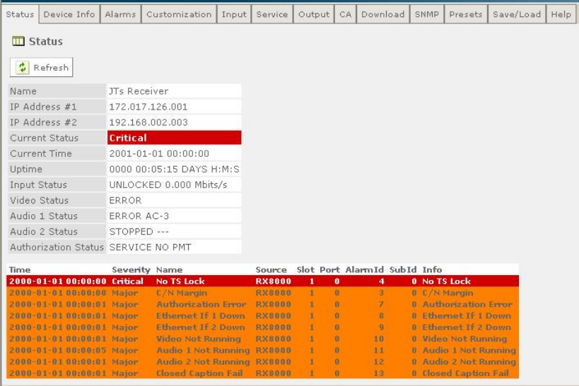
Remote Control
Figure 4.1 Typical Web Browser Status Page
For more information on the Web Browser interface and a description of the
available web pages, see Chapter 5, Web Browser Control.
4.5 SNMP
Simple Network Management Protocol (SNMP) is available as a standard feature on
all of the RX8000 Series Receivers.
SNMP is a network protocol used to monitor network-attached devices for conditions
that warrant administrative attention. SNMP consists of a set of standards for
network management, including an application layer protocol, a database schema,
and a set of data objects.
The RX8000 Series Receivers support SNMP Versions 1, 2C and 3.
For more detailed information on SNMP remote control, contact Ericsson.
4.5.1 Setting Up SNMP Remote Control
SNMP remote control is enabled by default.
To set up SNMP remote control:
1. Ensure the Web Browser Interface is connected and working.
2. From the browser SNMP tab, select the version of SNMP required (V2C or V3).
EN/LZT 790 0005 R1A
4-6
Remote Control
3. Ensure the trap community, read-write community and read-only community are
configured as public or private in the same way as the MIB browse or SNMP
application being used.
4.5.2 Downloading the MIB
SNMP exposes management data in the form of variables on the managed systems,
which describe the system configuration.
The SNMP Management Information Base (MIB) stored on each unit defines which
information (variables) should be monitored.
The MIB may be downloaded from the unit as a zip file using the Web Browser
interface, see Chapter 5, Web Browser Control.
These variables can then be queried (and set) by managing applications.
Please refer to the managing application documentation for compiling third-party
MIBs.
EN/LZT 790 0005 R1A
4-7
Remote Control
EN/LZT 790 0005 R1A
4-8
BLANK

5 Web Browser Control
Chapter 5
Contents
5.1 Introduction...........................................................................................5-3
5.1.1 Setting up Web Browser Control ..........................................................5-3
5.1.2 Using the Web Browser Interface......................................................... 5-3
5.2 Web Pages ........................................................................................... 5-6
5.2.1 Status ...................................................................................................5-6
5.2.2 Device Info............................................................................................ 5-7
5.2.2.1 Device Info > Build................................................................................ 5-8
5.2.2.2 Device Info > Environment ................................................................... 5-8
5.2.2.3 Device Info > Network Settings ............................................................ 5-9
5.2.2.4 Device Info > Modules..........................................................................5-9
5.2.2.5 Device Info > Trap Destination Table ................................................. 5-10
5.2.3 Alarms ................................................................................................5-11
5.2.4 Customization.....................................................................................5-12
5.2.4.1 Licensed Features .............................................................................. 5-13
5.2.5 CA....................................................................................................... 5-14
5.2.5.1 CA Service Status ..............................................................................5-15
5.2.6 Input Main Page (Satellite Input Card RX8200/HWO/DVBS2 fitted) ..5-15
5.2.6.1 Input > SAT Input................................................................................ 5-16
5.2.6.2 Input > SAT Input > Configuration RF # 1-4 .......................................5-17
5.2.7 Input Main Page (I/P Input Card RX8XX/HWO/GIGE fitted)............... 5-18
5.2.7.1 Input > IP Input ................................................................................... 5-19
5.2.8 Input (8VSB Input Card RX8320/HWO/8VSB fitted) ..........................5-22
5.2.9 Input (G.703 ATM Input Card RX8XXX/HWO/G.703 fitted)................ 5-23
5.2.9.1 Input > G.703 Input............................................................................. 5-24
5.2.10 Service Plus........................................................................................ 5-25
5.2.11 Decode ...............................................................................................5-26
5.2.11.1 Decode > Advanced ........................................................................... 5-28
5.2.11.2 Decode > VBI-VANC ..........................................................................5-30
5.2.11.3 Decode > Splice ................................................................................. 5-33
5.2.11.4 Decode > DVB-Subtitles..................................................................... 5-33
5.2.11.5 Decode > Teletext .............................................................................. 5-34
5.2.12 Output.................................................................................................5-35
5.2.13 Download............................................................................................ 5-37
5.2.14 SNMP .................................................................................................5-38
5.2.15 Presets ...............................................................................................5-39
5.2.16 Save/Load ..........................................................................................5-40
5.2.17 Help ....................................................................................................5-42
EN/LZT 790 0005 R1A
5-1
Chapter 5
EN/LZT 790 0005 R1A
5-2
List of Figures
Figure 5.1 Web Page Overview............................................................................. 5-3
Figure 5.2 About dialog ......................................................................................... 5-4
Figure 5.3 Status Web Page ................................................................................. 5-6
Figure 5.4 Device Info Web Page.......................................................................... 5-7
Figure 5.5 Device Info > Build Web Page ............................................................. 5-8
Figure 5.6 Device Info > Environment Web Page ................................................. 5-9
Figure 5.7 Device Info > Network Settings Web Page .......................................... 5-9
Figure 5.8 Device Info > Modules Web Page...................................................... 5-10
Figure 5.9 Device Info > Trap Destination Table Web Page ............................... 5-10
Figure 5.10 Trap Destination Table > Add Item Web Page................................... 5-10
Figure 5.11 Alarms Web Page .............................................................................. 5-12
Figure 5.12 Customization Web Page................................................................... 5-12
Figure 5.13 Licensed Features Web Page............................................................ 5-13
Figure 5.14 CA Web Page .................................................................................... 5-14
Figure 5.15 CA Service Status Web Page ............................................................ 5-15
Figure 5.16 Input Main Page (Satellite Input Card fitted) ...................................... 5-15
Figure 5.17 Satellite Input Web Page.................................................................... 5-16
Figure 5.18 Configuration RF#1 Web Page.......................................................... 5-17
Figure 5.19 Input Main Page (IP Card fitted) ........................................................ 5-18
Figure 5.20 Input > IP Input Web Page................................................................. 5-20
Figure 5.21 Clear Arp Confirmation Window......................................................... 5-21
Figure 5.22 Clear ARP Success Window.............................................................. 5-22
Figure 5.23 Input Main Page (8VSB Input Card fitted).......................................... 5-22
Figure 5.24 Input Main Page (G.703 ATM Input Card fitted)................................. 5-23
Figure 5.25 Input > G.703 Input Web Page........................................................... 5-24
Figure 5.26 Service Plus Web Page...................................................................... 5-25
Figure 5.27 Decode Web Page ............................................................................. 5-27
Figure 5.28 Decode > Advanced Web Page ......................................................... 5-28
Figure 5.29 Decode > VBI-VANC Web Page ........................................................ 5-31
Figure 5.30 Decode > Splice Web Page ............................................................... 5-33
Figure 5.31 Decode > DVB-Subtitles Web Page................................................... 5-34
Figure 5.32 Decode > Teletext Web Page ............................................................ 5-35
Figure 5.33 Output Web Page............................................................................... 5-36
Figure 5.34 Download Web Page.......................................................................... 5-37
Figure 5.35 SNMP Web Page ............................................................................... 5-38
Figure 5.36 Preset Web Page ............................................................................... 5-39
Figure 5.37 Save/Load Web Page ........................................................................ 5-41
Figure 5.38 Help Web Page .................................................................................. 5-42
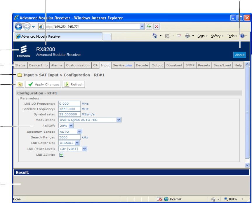
Chapter 5
5.1 Introduction
This chapter describes the features and options provided by the Web Browser
interface menus and web pages for controlling the RX8000 Series Receivers
remotely.
The Web Browser interface is available as a standard feature on all of the RX8000
Series Receivers.
5.1.1 Setting up Web Browser Control
For information on how to set up Web Browser remote control, see Chapter 4,
Remote Control.
5.1.2 Using the Web Browser Interface
The Web Browser Interface displays various web pages, corresponding to the
different functions of the receiver, in the format shown in Figure 5.1.
Figure 5.1 Web Page Overview
Unit Model Number
and Name About
button
Header
Function Tabs
Navi
g
ation Path
Toolbar
Main Web Page
Results Frame
EN/LZT 790 0005 R1A
5-3
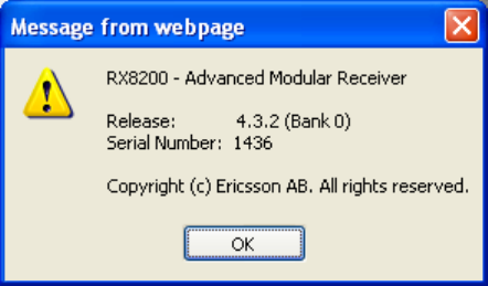
Chapter 5
• Header – The header of the web page displays the Ericsson logo and the unit
model number name. At the right-hand side of the header an About button
which, when clicked, displays an information dialog about the unit, including the
software version number. Click the OK button to close the dialog.
Figure 5.2 About dialog
• Function Tabs – The web pages for control and monitoring of specific functions
are accessed by selecting the appropriate function tab along the top of each
web page. When you switch between tabs, the browser remembers the path for
each tab.
• Navigation Path – The web pages are organized into a tree-like structure, like
the directory on a computer. The current complete navigation path is always
displayed at the top of the web page, which shows the route taken to the
currently displayed web page. To return to a higher level (parent) web page
(folder), simply click on the relevant name link in the Navigation Path or click or
the Top Level Folder in the toolbar.
• Toolbar – The toolbar provides various tools/buttons, depending on the web
page selected. Various icons, buttons and symbols can appear in the Toolbar,
depending on the web page displayed. See Table 5.1 for details.
• Main Web Page – The main content of the web page (or folder) displays the
parameters and their current values. Some parameters will be modifiable by
overtyping, by selecting an option from a drop-down menu or by placing a tick in
a checkbox, as required. Any changes made will not be applied to the unit until
the Apply Changes button is clicked in the Toolbar.
• Results Frame – The result frame at the bottom of the screen shows the results
of command actions. SUCCESS, SUCCESS with warnings or ERROR may be
displayed, with further details as appropriate for more complex actions.
The following table lists the various icons, buttons and other symbols used in these
web pages.
EN/LZT 790 0005 R1A
5-4
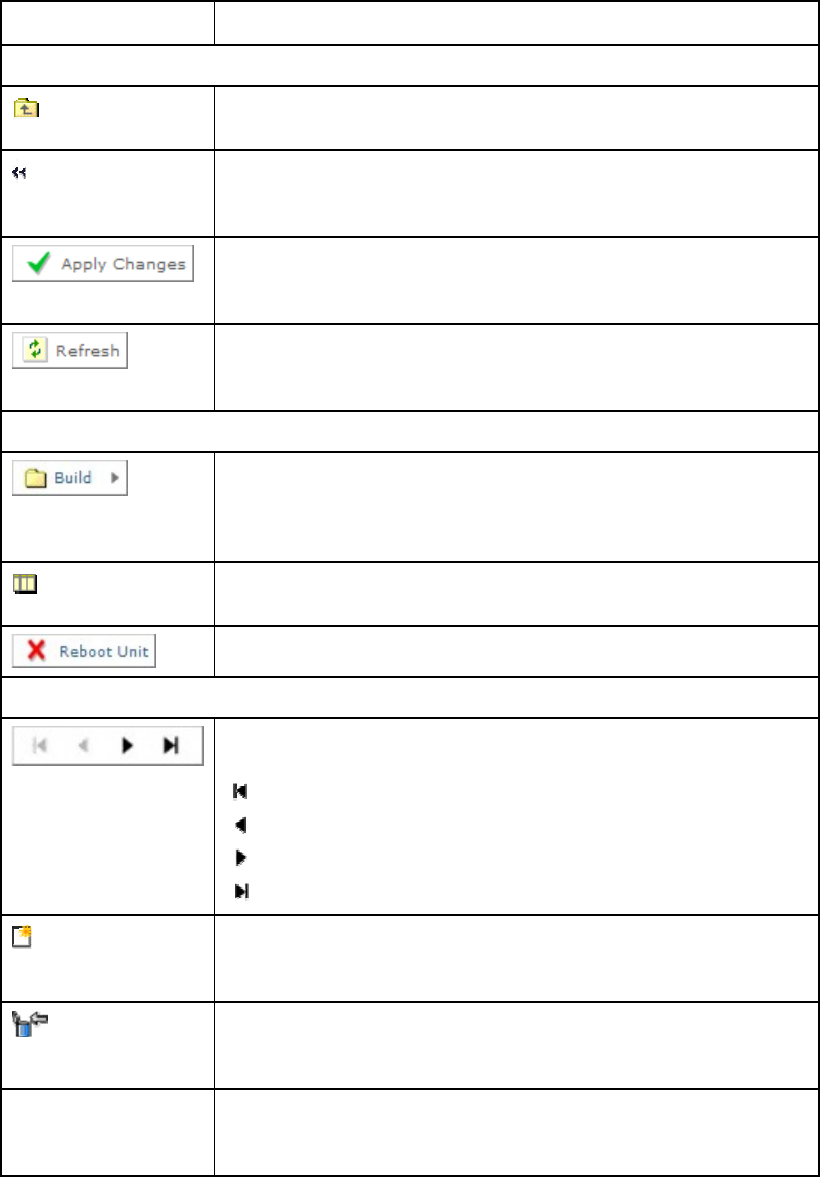
Chapter 5
Table 5.1 Web Page Icons, Buttons and Symbols
Item Description
Navigation
Click on this icon to navigate one step up (to the parent folder) in
the folder structure.
Click on this icon to navigate back to the previous view. This icon
typically appears when you are editing a single record in a table
or a sub-table.
Click on this button to apply the changes you have made to
parameters in this web page. The result of your actions will be
shown in the result window below.
Click on this button to refresh the current screen. This may be
useful if the screen contains read-only status parameters such as
measured bitrates.
Parameter Presentation
The folder icon is used to represent a web page in the system. A
folder is similar to a directory in a file system. The button shown
left indicates that a further sub-folder or lower-level web page is
available by clicking on the button.
This icon is used to represent a table. A table normally consists of
multiple items, where each item consists of several fields.
Click on this button to reboot the unit.
Table Operations
These buttons are used to navigate a table of data when it is too
large to fit into one screen. The symbols are:
go to start
previous screen
next screen
go to end.
Add Item In case you are allowed to add items to a table, press this button
to add a new item into the table. You will be taken to the "New
item" screen in the table.
Delete Selected In case you are allowed to delete items from a table, press this
button to delete selected items. You select items by clicking the
checkboxes in front of each row.
Delete All Press this button to delete all items in a table. Note that this will
delete the entire table, not only the items you may see on the
screen at any time.
EN/LZT 790 0005 R1A
5-5
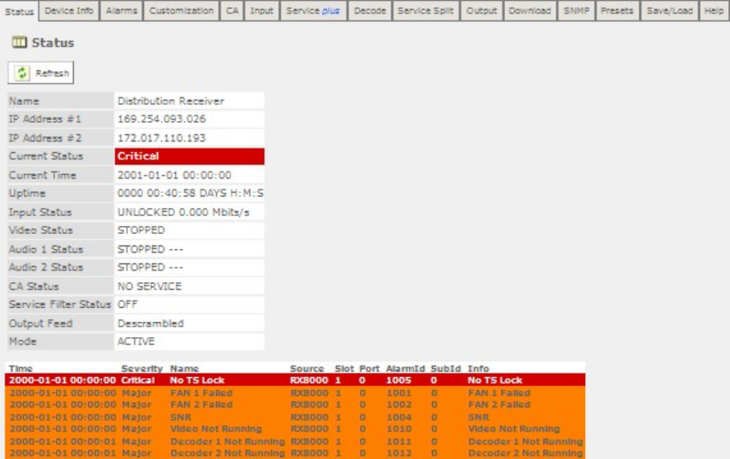
Chapter 5
5.2 Web Pages
5.2.1 Status
To use the receiver Web Browser Interface, the IP address assigned to the receiver
control port in the front panel system menu should be entered into the address field
of the Web browser.
Provided that the network is correctly configured, the following status page should
be automatically loaded and displayed.
Figure 5.3 Status Web Page
This page provides a number of top-level status items:
• Name – Shows the configured device name for this product.
• IP (Internet Protocol) Address #1 – The configured IP address #1 for the
product.
• IP Address #2 – The configured IP address #2 for the product.
• Current Status – The current top level alarm status for the Receiver.
• Current Time – The time taken from the input Transport Stream.
• Uptime – The elapsed time since power-up.
• Input Status – The input TS lock status on the decoder.
• Video Status – The decode status of the current video stream.
EN/LZT 790 0005 R1A
5-6
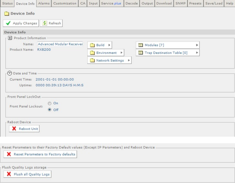
Chapter 5
• Audio Status – The decode status of the current audio stream.
• CA (Conditional Access) Status - The status of the encryption authorizations.
• Output Feed – The status of the output.
• Mode – Indicates whether unit configuration is active or redundant.
A small window located at the bottom left of the Status Page will show events raised
and all the necessary details of those events.
The About button, located on the top right-hand side of the Status page shows,
when selected, details of the receiver such as software release and serial number.
5.2.2 Device Info
The Device Info page provides access to system level settings of the receiver.
To view this web page, select the Device Info tab from the top of the current web
page.
Figure 5.4 Device Info Web Page
The following fields are displayed on this web page:
EN/LZT 790 0005 R1A
5-7
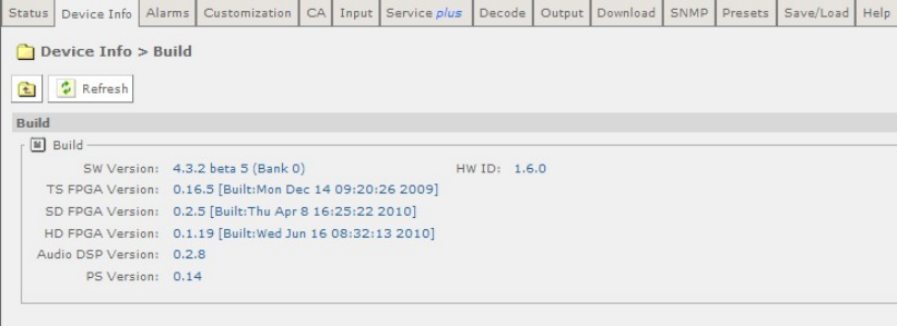
Chapter 5
• Name – This field contains a name string that can be assigned by the user. The
last saved name is displayed on power-up but may be replaced by the user. The
default name is the receiver model name.
• Product Name – The name and/or model of the product.
• Current Time – The time taken from the input Transport Stream.
• Uptime – The elapsed time since power-up.
• Front Panel Lockout - Indicates whether the front panel controls are active or
inactive.
Three buttons are provided on this page to allow for Rebooting and resetting of the
equipment:
• Reboot Unit – Selecting this button will perform a hardware reset of the
receiver.
• Reset Parameters to Factory Defaults – Selecting this button will set all
parameters to their factory default values (except for the network IP parameters
e.g. IP address and subnet mask) and perform a hardware reset of the receiver.
• Flush all Quality Logs – Selecting this button will flush all the quality logs.
A number of further web pages are accessible from the Device Info page and these
are described in the following paragraphs.
5.2.2.1 Device Info > Build
This page gives details of the build and version information for the equipment.
To view this page, select the Build button from the Device Info Page.
Figure 5.5 Device Info > Build Web Page
There are no fields on this page, which may be edited by the user.
5.2.2.2 Device Info > Environment
This page gives details of the physical environment of the Equipment i.e.
temperature and fan speeds.
EN/LZT 790 0005 R1A
5-8
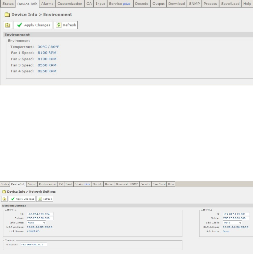
Chapter 5
To view this page, select the Environment button from the Device Info Page.
Figure 5.6 Device Info > Environment Web Page
There are no fields on this page, which may be edited by the user. Selecting the
Refresh button will ensure that the latest information is displayed from the current
values of the equipment.
5.2.2.3 Device Info > Network Settings
This page gives details of settings for control 1 and 2 networks.
To view this page, select the Network Settings button from the Device Info Page.
Figure 5.7 Device Info > Network Settings Web Page
Fields on this page allow the user to enter values for IP address and Subnet and to
select an appropriate value for Link Configuration from a drop down menu. These
values may be entered or updated for Control 1 and 2 networks. The Gateway
address, which is common for both networks, may be entered or updated in the
appropriate field.
Any changes made to the current values may be incorporated into this page by
selecting the Apply Changes button. Selecting the Refresh button will ensure that
the latest information is being displayed from the current values of the equipment.
5.2.2.4 Device Info > Modules
This page gives a list of all modules contained in the equipment chassis.
To view this page, select the Modules button from the Device Info Page.
EN/LZT 790 0005 R1A
5-9
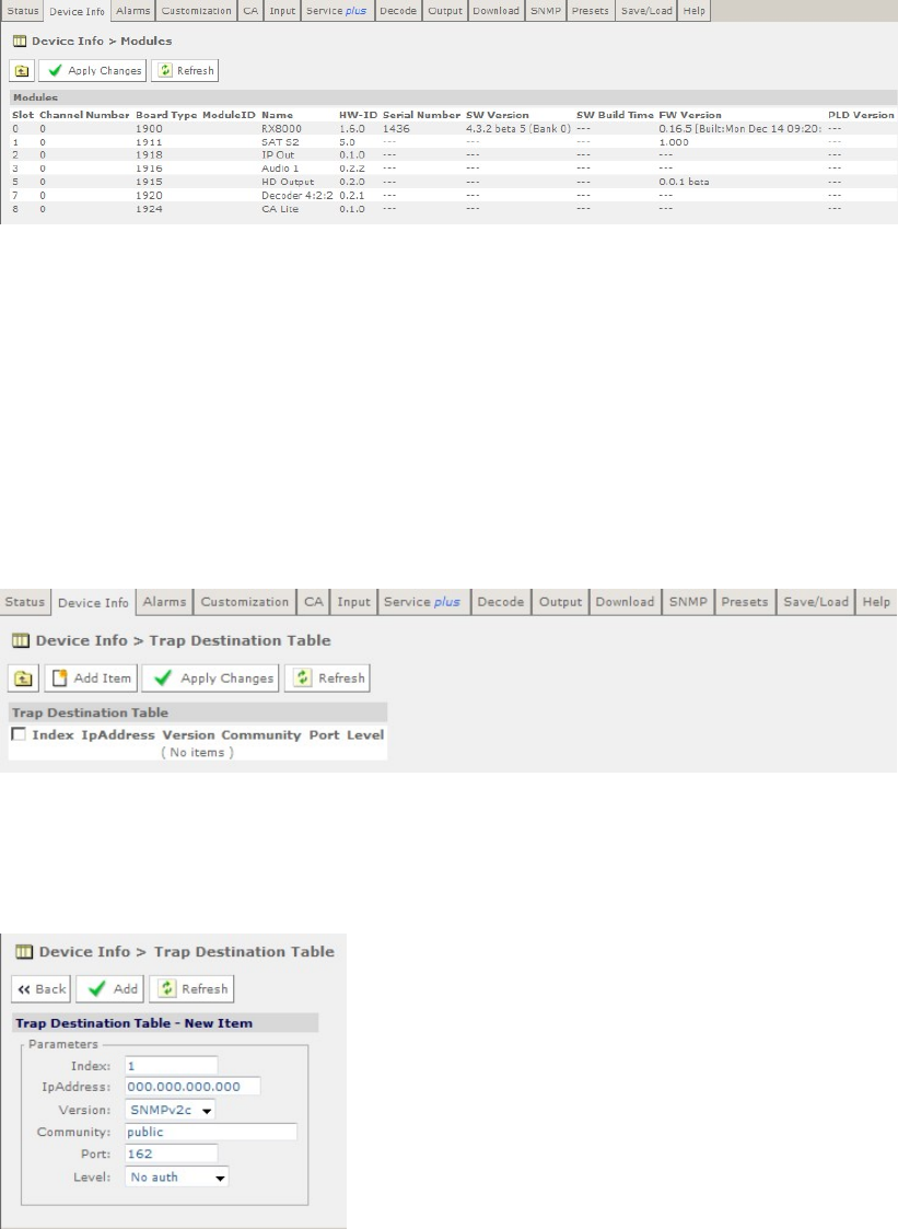
Chapter 5
Figure 5.8 Device Info > Modules Web Page
There are no fields on this page which may be edited by the user. Selecting the
Refresh button will ensure that the latest information is displayed from the current
values of the equipment.
5.2.2.5 Device Info > Trap Destination Table
When an alarm occurs within the equipment, an SNMP Trap message is sent to all
destinations and a list of these destinations is given in this web page.
To view this page, select the Trap Destination button from the Device Info page.
Figure 5.9 Device Info > Trap Destination Table Web Page
To add a new item to this page:
1. Select the Add Item button. The following page is displayed:
Figure 5.10 Trap Destination Table > Add Item Web Page
2. Enter the required values in the appropriate fields or select values from the drop-
down menus.
3. Select the Add button to add the item to the Trap Destination table.
EN/LZT 790 0005 R1A
5-10
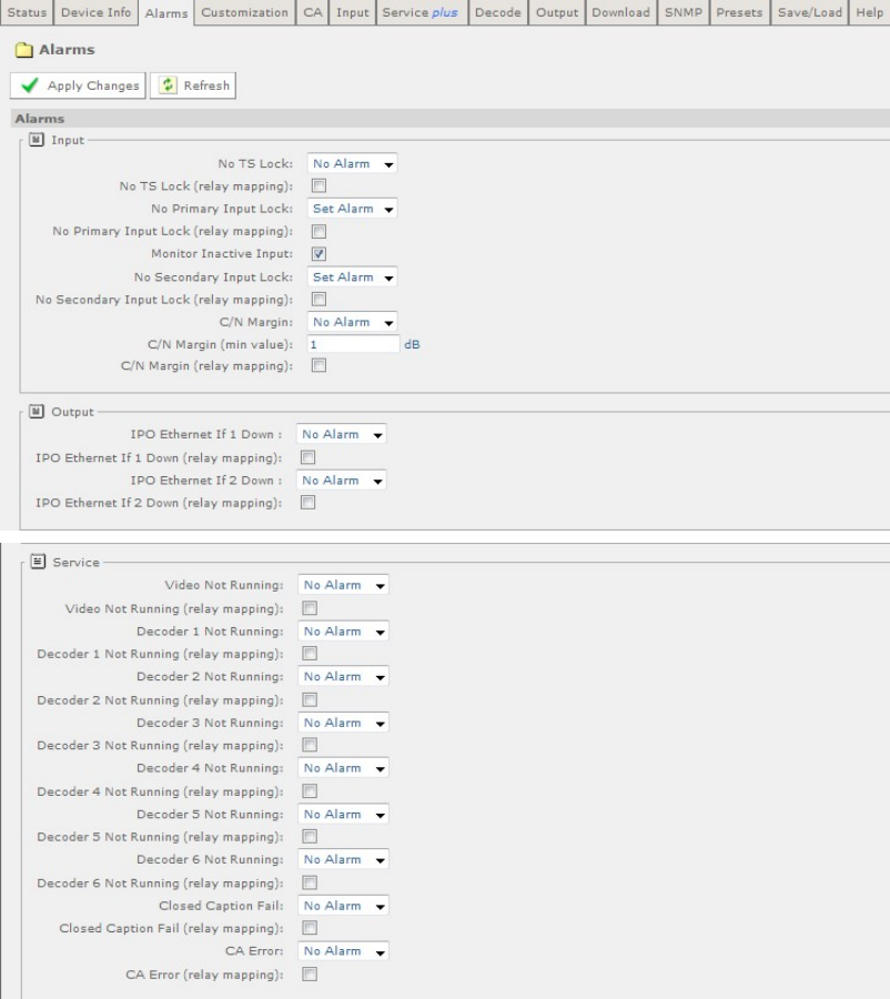
Chapter 5
4. Select the Back button to return to the Device Info > Trap Destination Table web
page.
5. Select the Apply Changes button to confirm additions.
Selecting the Refresh button will ensure that the latest information is being
displayed from the current values of the equipment.
5.2.3 Alarms
The alarms Page provides access to the alarms settings for the receiver.
To view this page, select the Alarms tab from the top of the current web page.
EN/LZT 790 0005 R1A
5-11
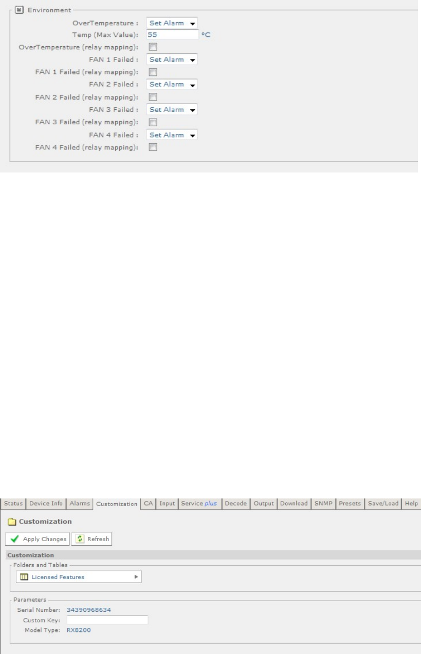
Chapter 5
Figure 5.11 Alarms Web Page
The contents of this page are composed mainly of fields with drop-down menus
which allow the setting or masking of various alarms and check boxes which can be
used to activate relay mapping. Two of the alarm fields, namely C/N (Carrier-to-
Noise) Margin and Over Temperature also have associated entry fields which allow
the user to enter a value which, if exceeded, will activate the alarm.
Setting an alarm enables the alarm to be shown on the alarm LED, the alarm status
displays and is recorded in the alarm log.
Any changes which are made to the alarm settings shown may be confirmed by
selecting the Apply Changes button. Selecting the Refresh button will ensure that
the latest information is being displayed from the current values of the equipment.
5.2.4 Customization
The Customization web page allows the user to view which licenses are enabled on
the equipment and to enable further licenses as purchased by entering the custom
key provided.
To view this page, select the Customization tab from the top of the current web
page.
Figure 5.12 Customization Web Page
EN/LZT 790 0005 R1A
5-12
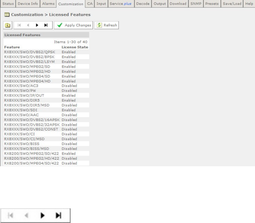
Chapter 5
The Parameters section of this web page allows the user to enable further licenses
by entering the custom key provided (when a license is purchased) in the Custom
Key field. Once the custom key has been entered, the unit will need to be rebooted
for the key to become effective.
The custom key is a 22 decimal digit number. License keys are supplied by Ericsson
Customer Support upon requirement for a new licensed feature.
Any changes, which are made to the Licensed Features shown, may be confirmed
by selecting the Apply Changes button. Selecting the Refresh button will ensure
that the latest information is being displayed from the current values of the
equipment.
The Licensed Features button allows the user to view which licenses are currently
enabled.
5.2.4.1 Licensed Features
To view this web page, select the Licensed Features button.
Figure 5.13 Licensed Features Web Page
In this page the back and forward buttons allow access to the complete list of
available licenses:
Any changes which are made to the Licensed Features shown may be confirmed by
selecting the Apply Changes button. Selecting the Refresh button will ensure that
the latest information is being displayed from the current values of the equipment.
EN/LZT 790 0005 R1A
5-13
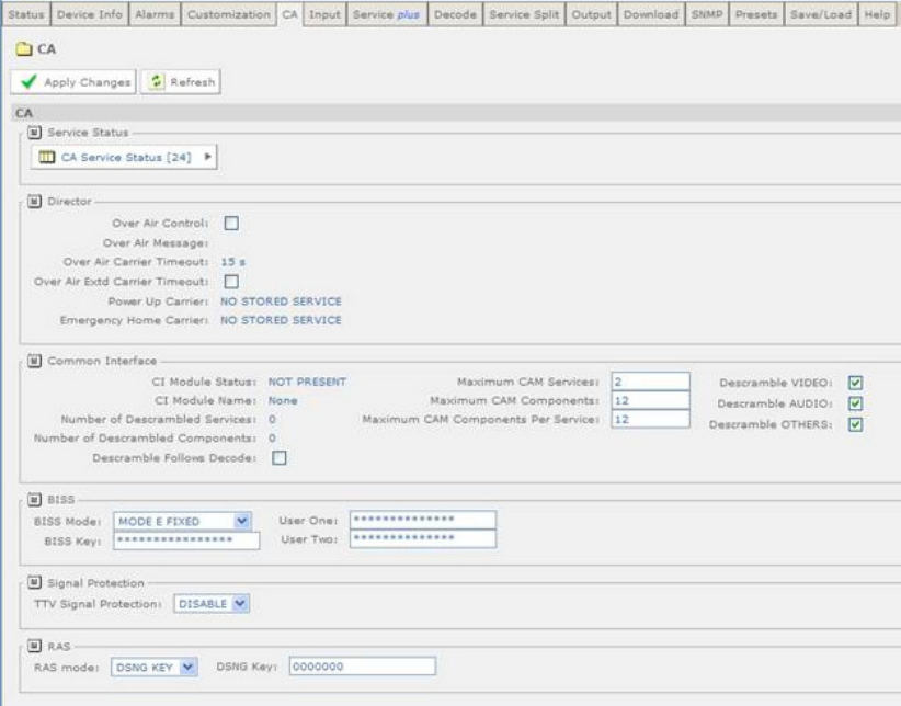
Chapter 5
5.2.5 CA
This page allows viewing of the Conditional Access (CA) Service Status and
activation of various Director controls.
To view this page, select the CA tab from the top of the current web page.
Figure 5.14 CA Web Page
The Director section of this web page allows the user to view the current settings
for the Director and to activate or deactivate various functions as required.
The BISS section of this web page allows the user to view and modify the settings
for Basic Interoperable Scrambling System (BISS). These are Mode 1, Mode E
Fixed, Mode E Ericsson, Mode E User One, Mode E User Two. Mode 1 uses an
unencrypted key for the BISS key. Mode E uses an encrypted key, which uses
either an internal code word or User One or User Two to decrypt, depending on the
mode.
The Signal Protection section of this web page allows the user to enable or disable
signal protection.
The RAS section of this web page allows the user to select Digital Satellite News
Gathering (DSNG) or Fixed Key mode and input a 7-digit DSNG key.
EN/LZT 790 0005 R1A
5-14
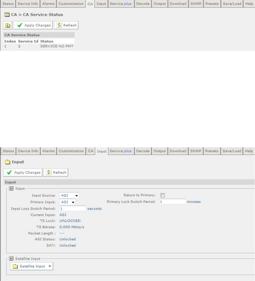
Chapter 5
Any changes which are made to the CA page functions may be confirmed by
selecting the Apply Changes button. Selecting the Refresh button will ensure that
the latest information is being displayed from the current values of the equipment.
The CA Service Status button allows the user to view the Conditional Access
Status Table.
5.2.5.1 CA Service Status
To view this page, select the CA Service Status button on the CA page.
Figure 5.15 CA Service Status Web Page
There are no fields which may be edited by the user on this page. Selecting the
Refresh button will ensure that the latest information is displayed from the current
values of the equipment.
5.2.6 Input Main Page (Satellite Input Card RX8200/HWO/DVBS2 fitted)
This page allows the user to view and edit the various inputs to the receiver. To view
this page, select the Input tab from the top of the current web page.
Figure 5.16 Input Main Page (Satellite Input Card fitted)
The following user-editable fields are displayed on this web page:
EN/LZT 790 0005 R1A
5-15
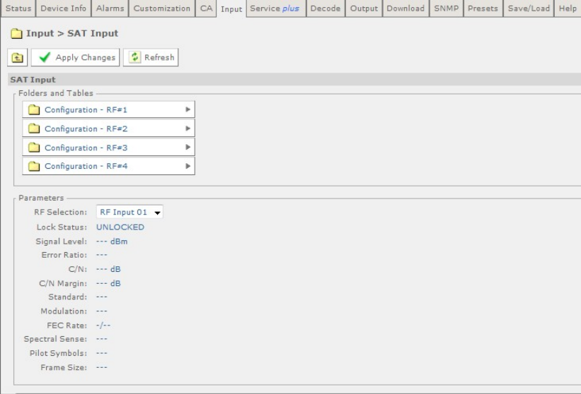
Chapter 5
• Input Source – allows a choice of Source Selection Mode from the drop-down
menu.
• Primary Input – allows selection of the primary input to the receiver.
• Input Loss Switch Period – allows the user to define a period, in seconds,
before the unit switches to the alternate input (either Input Source or Primary).
• Return to Primary – checking this box specifies that when the Primary is locked
the unit will always return to the Primary after a timeout period.
• Primary Lock Switch Period - allows the user to define a period, in minutes,
before switching back to Primary, if Primary is not currently selected.
Any changes which are made to the Input page may be confirmed by selecting the
Apply Changes button. Selecting the Refresh button will ensure that the latest
information is being displayed from the current values of the equipment.
The Satellite Input button gives access to the Satellite Input folder web page.
5.2.6.1 Input > SAT Input
To view this web page, select the Satellite Input button from the Input page.
Figure 5.17 Satellite Input Web Page
The only field which may be edited by the user is the RF Selection field which
allows selection of the appropriate RF Input.
EN/LZT 790 0005 R1A
5-16
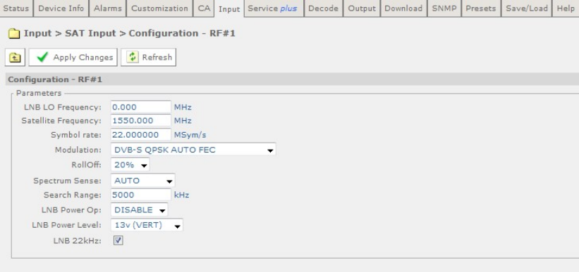
Chapter 5
There are also four Configuration buttons which allow the viewing and setting of
the tuning parameters for the four possible RF inputs.
Any changes which are made to the Satellite Input page may be confirmed by
selecting the Apply Changes button. Selecting the Refresh button will ensure that
the latest information is being displayed from the current values of the equipment.
5.2.6.2 Input > SAT Input > Configuration RF # 1-4
To view the Configuration settings for the chosen input, select the appropriate
Configuration button.
Figure 5.18 Configuration RF#1 Web Page
The following user-editable fields are displayed on this page:
• LNB (Low-Noise Block Converter) LO (Local Oscillator) Frequency – allows
the input of a frequency in MHz, in steps of 1 kHz.
• Satellite Frequency – allows the input of a frequency in MHz, in steps of 1 kHz.
• Symbol Rate – allows the input of a value in MSym/s.
• Modulation – allows the selection of a modulation type from a drop-down menu.
Available modulation types are license-dependant.
• RollOff – allows the selection of a rolloff rate from a drop-down menu.
• Spectrum Sense – allows the selection of the spectrum sense from a drop-
down menu.
• Search Range – allows the input of a range in kHz.
• LNB Power Op – allows the user to enable/disable the LNB Power Op.
• LNB Power Level – allows the selection of the LNB Power Level from a drop-
down menu. This setting is applied only when the LNB Power Op field is set to
ENABLE.
EN/LZT 790 0005 R1A
5-17
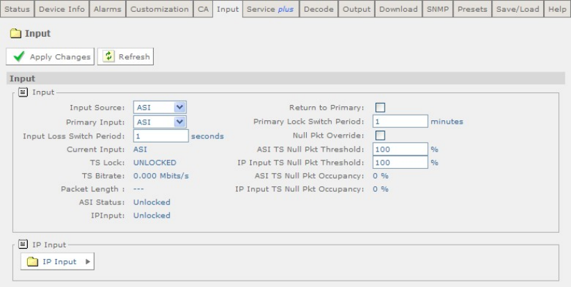
Chapter 5
• LNB 22 kHz – this check box allows the LNB 22 kHz signal to be activated.
Any changes which are made to the Configuration page may be confirmed by
selecting the Apply Changes button. Selecting the Refresh button will ensure that
the latest information is being displayed from the current values of the equipment.
5.2.7 Input Main Page (I/P Input Card RX8XX/HWO/GIGE fitted)
This page allows the user to view and edit the various inputs to the receiver. To view
this page, select the Input tab from the top of the current web page.
Figure 5.19 Input Main Page (IP Card fitted)
The following user-editable fields are displayed on this web page:
• Input Source – allows a choice of Source Selection Mode from the drop-down
menu.
• Primary Input – allows selection of the primary input to the receiver.
• Input Loss Switch Period – allows the user to define a period, in seconds,
before the unit switches to the alternate input (either Input Source or Primary).
• Return to Primary – checking this box specifies that when the Primary is locked
the unit will always return to the Primary after a timeout period.
• Primary Lock Switch Period - allows the user to define a period, in minutes,
before switching back to Primary, if Primary is not currently selected.
• Null Pkt Override – checking this box causes the input to switch when the unit
detects a Transport Stream with more null packets than are defined in the
percentage threshold item.
• ASI TS Null Pkt Threshold – allows the user to determine the ASI null packet
occupancy percentage before switch.
EN/LZT 790 0005 R1A
5-18
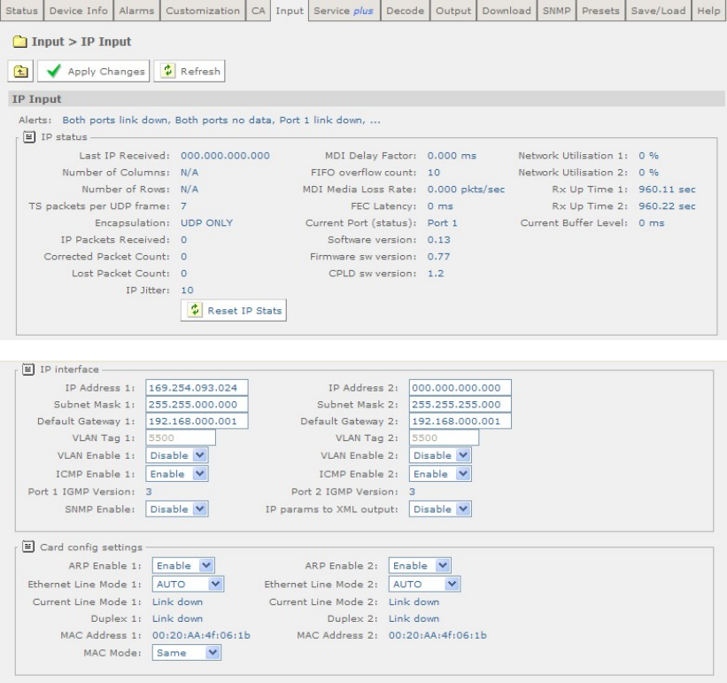
Chapter 5
• IP Input TS Null Pkt Threshold – allows the user to determine the IP Input null
packet occupancy percentage before switch. This option is available for all
inputs (G.703, S2, etc.)
An IP Input button is provided on this page which gives access to a further web
page. This is described in the following section.
Any changes which are made to the Input page may be confirmed by selecting the
Apply Changes button. Selecting the Refresh button will ensure that the latest
information is being displayed from the current values of the equipment.
5.2.7.1 Input > IP Input
This page allows the user to view and edit the various IP inputs to the receiver. To
view this page, select the IP Input button from the Input web page.
EN/LZT 790 0005 R1A
5-19
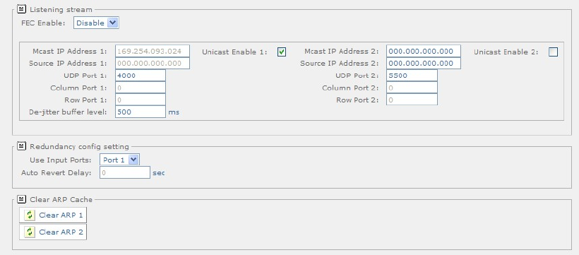
Chapter 5
Figure 5.20 Input > IP Input Web Page
The following user-editable fields are displayed on this web page:
User-editable fields in the IP Interface Section:
• IP Address 1/2 – allows the user to input the relevant IP address.
• Subnet Mask 1/2 – allows the user to input the relevant Subnet Mask address.
• Default Gateway 1/2 – allows the user to input the relevant Default Gateway
address.
• VLAN (Virtual Local Area Network) Tag 1/2 - allows the user to input the
relevant VLAN Tag Value.
• VLAN Enable 1/2 - allows the user to enable/disable the VLAN.
• ICMP (Internet Control Message Protocol) Enable 1/2 – allows the user to
enable/disable network 1/2 to ping the input (and Port 1/2).
• SNMP Enable – allows the user to enable/disable the SNMP facility via the input
port.
• IP params to XML output – allows the user to enable/disable the sending of the
IP parameters out as XML from the input port.
User-editable fields in the Card Config Settings section:
• ARP Enable 1/2 – allows the user to enable/disable the ARP on Network 1/2.
• Ethernet Line Mode 1/2 – allows the user to set the Ethernet line mode for
Network Interface 1/2.
• MAC Mode – allows the user to change the current MAC Mode.
User-editable fields in the Listening Stream Section:
• FEC Enable – allows the user to enable/disable FEC. This facility is only
available when FEC is licensed.
EN/LZT 790 0005 R1A
5-20
Chapter 5
• Mcast IP Address 1/2 – allows the user to set the Multicast IP Address for the
primary stream on Port 1/2.
• Source IP Address 1/2 – allows the user to set the Source IP Address for the
primary stream on Port 1/2.
• UDP Port 1/2 – allows the user to set the UDP Port Address for the primary
stream on Port 1/2.
• Column Port 1/2 – allows the user to set the Column Port Address for the
primary stream on Port 1/2.
• Row Port 1/2 – allows the user to set the Row Port Address for the primary
stream on Port 1/2.
• De-Jitter Buffer Level – allows the user to enter a value in milliseconds.
• Unicast Enable 1/2 – allows the user to enable Unicast for Port 1/2.
User-editable fields in the Redundancy Config Setting:
• Use Input Ports – allows the user to select the appropriate input port.
• Auto Revert Delay – allows the user to enter a value in seconds.
Two buttons, Clear ARP 1 and Clear ARP 2, are provided to allow the user to clear
the ARP cache for port 1 or 2. If these are selected the following window is
displayed:
Figure 5.21 Clear Arp Confirmation Window
If OK is selected, the Input>I/P Input page is displayed showing that the operation
has been successful.
EN/LZT 790 0005 R1A
5-21
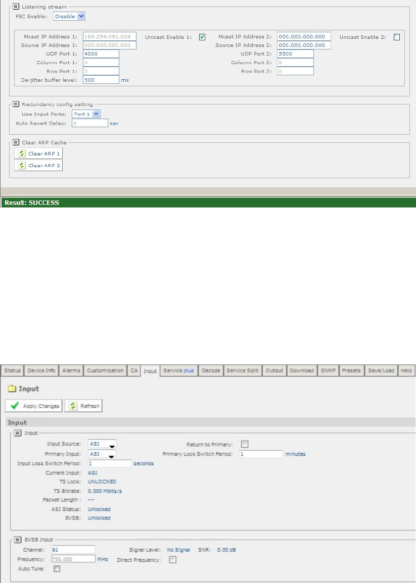
Chapter 5
Figure 5.22 Clear ARP Success Window
Any changes which are made to the Input>IP Input page may be confirmed by
selecting the Apply Changes button. Selecting the Refresh button will ensure that
the latest information is being displayed from the current values of the equipment.
5.2.8 Input (8VSB Input Card RX8320/HWO/8VSB fitted)
This page allows the user to view and edit the various inputs to the receiver. To view
this page, select the Input tab from the top of the current web page.
Figure 5.23 Input Main Page (8VSB Input Card fitted)
User-editable fields in the Input Section:
• Input Source – allows a choice of Source Selection Mode from the drop-down
menu.
EN/LZT 790 0005 R1A
5-22
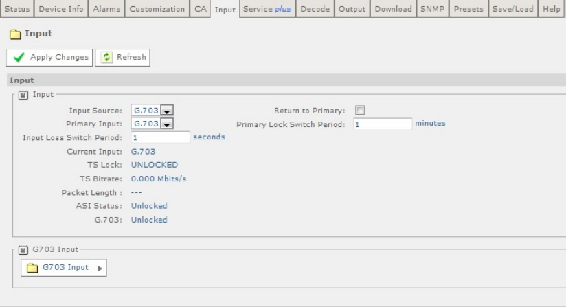
Chapter 5
• Primary Input – allows selection of the primary input to the receiver.
• Input Loss Switch Period – allows the user to define a period, in seconds,
before the unit switches to the alternate input (either Input Source or Primary).
• Return to Primary – checking this box specifies that when the Primary is locked
the unit will always return to the Primary after a timeout period.
• Primary Lock Switch Period - allows the user to define a period, in minutes,
before switching back to Primary, if Primary is not currently selected.
User-editable fields in the 8VSB Section:
• Channel – allows the user to define a channel to monitor.
• Frequency – Displays the frequency of the displayed channel.
• Direct Frequency – checking this box enables the Direct Frequency option.
• Auto Tune – checking this box enables the Auto Tune option.
Any changes which are made to the Input page may be confirmed by selecting the
Apply Changes button. Selecting the Refresh button will ensure that the latest
information is being displayed from the current values of the equipment.
5.2.9 Input (G.703 ATM Input Card RX8XXX/HWO/G.703 fitted)
This page allows the user to view and edit the various inputs to the receiver. To view
this page, select the Input tab from the top of the current web page.
Figure 5.24 Input Main Page (G.703 ATM Input Card fitted)
The following user-editable fields are displayed on this web page:
EN/LZT 790 0005 R1A
5-23
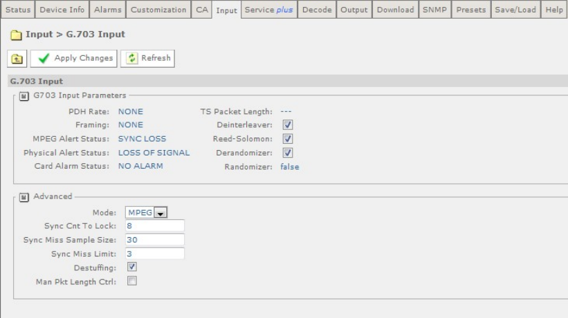
Chapter 5
User-editable fields in the Input Section:
• Input source – allows a choice of Source Selection from the drop-down menu.
• Primary Input – allows selection of the primary input to the receiver.
• Input Loss Switch Period – allows the user to define a period, in seconds,
before the unit switches to the alternate input (either Input Source or Primary).
• Return to Primary – checking this box specifies that when the Primary is locked
the unit will always return to the Primary after a timeout period.
• Primary Lock Switch Period - allows the user to define a period, in minutes,
before switching back to Primary, if Primary is not currently selected.
Any changes which are made to the Input page may be confirmed by selecting the
Apply Changes button. Selecting the Refresh button will ensure that the latest
information is being displayed from the current values of the equipment.
There is a G.703 button on this page which gives access to a further web page. This
is described in the following section.
5.2.9.1 Input > G.703 Input
To view this web page, select the G.703 button from the previous web page.
Figure 5.25 Input > G.703 Input Web Page
The following user-editable fields are displayed on this web page:
User-editable fields in the G.703 Input Section:
• Deinterleaver – checking this box enables the Deinterleaver function.
• Reed-Solomon – checking this box enables the Reed-Solomon function.
EN/LZT 790 0005 R1A
5-24

Chapter 5
• Derandomizer – checking this box enables the Derandomizer function.
User-editable fields in the Advanced Section:
• MPEG – allows the selection of the input mode from a drop-down menu.
• Sync Cnt to Lock – allows the user to input an appropriate value.
• Sync Miss Limit – allows the user to input an appropriate value.
• Destuffing – checking this box enables the destuffing function.
• Man Pkt Length Ctrl - checking this box enables this function.
Any changes which are made to the Input page may be confirmed by selecting the
Apply Changes button. Selecting the Refresh button will ensure that the latest
information is being displayed from the current values of the equipment.
5.2.10 Service Plus
This page allows access and editing of the various encryption and encoding
services available to the receiver.
To view this page, select the Service Plus tab from the top of the current web page.
Figure 5.26 Service Plus Web Page
In the Service Control Table the only fields which may be edited by the user are the
Decrypt and Decode checkboxes. Further details of the PID Info can be viewed by
placing the cursor over the word Details.
To edit the service selection:
1. Go to the Output tab page to select a filter mode, a bit rate type and desired bit
rate, if in CBR mode.
2. Choose a service to decode by placing a tick in the relevant Decode checkbox.
Note: This equipment is a single-service Decoder. Only 1 box may be selected by
placing as tick in the Decode checkbox.
3. If decryption is required place a tick in the relevant Decrypt checkbox. If MSD
license is selected, more than one MSD checkbox can be selected.
EN/LZT 790 0005 R1A
5-25
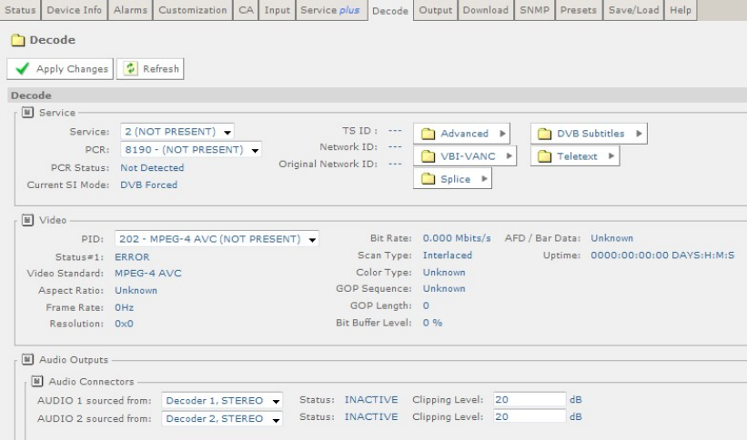
Chapter 5
4. If the MSD license is selected, and service filter mode is set to ‘Multiservice’ in
the Output tab, the services to be fitted can be added by ticking the filter
checkbox.
5. If service filter mode is set to ‘Remap’ in the Output tab, service PIDs may be
remapped by selecting ‘remap config’ under PID info. New PIDs for each
available components may be entered on the ‘Remap to PID’ box.
Other details about the service are available by hovering over the relevant table
column. Information is presented as a tooltip.
Any changes which are made to the Service Plus page may be confirmed by
selecting the Apply Changes button. Selecting the Refresh button will ensure that
the latest information is being displayed from the current values of the equipment.
5.2.11 Decode
This page allows access to the video, audio and decoding functions of the receiver.
To view this page, select the Decode tab from the top of the current page.
EN/LZT 790 0005 R1A
5-26

Chapter 5
Figure 5.27 Decode Web Page
The following user-editable fields are displayed on this page.
User-editable fields in the Service section:
• Service – allows the selection of the decode service is to be used from a drop-
down menu
• PCR - allows the selection of the PCR to be used from a drop-down menu. By
default, this is the PCR of the selected decode Service.
User-editable fields in the Video Section:
• PID (Program ID) - allows the selection of the PID to be used from a drop-down
menu.
User-editable fields in the Audio Output section (only available when an Audio Card
is fitted):
• Audio 1/2 sourced from – allows the selection of the source of Audio 1 from a
drop-down menu. Up to Audio 3/4 sources may be selected if 2 Audio Cards are
fitted.
• Clipping Level – allows the input of the clipping level of the audio source in dB.
User-editable fields in the SDI Embedding section (licensed feature):
• Group 1-4 – allows the selection of the group from a drop-down menu.
User-editable fields in the Audio Decoders section:
EN/LZT 790 0005 R1A
5-27
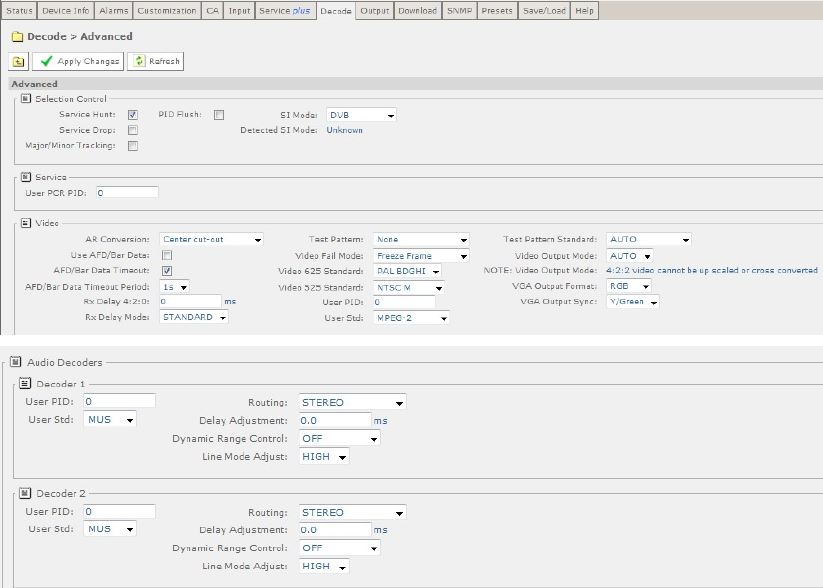
Chapter 5
• Decode Mode – allows the selection of the decode mode from a drop-down
menu.
User-editable fields in the Decoders 1-6 sections (number of audio decoders is
license and model dependent):
• PID – allows the selection of an PID audio for decode from a drop-down menu.
• Gain – allows the input of a value in dB.
Any changes which are made to the Decode page may be confirmed by selecting
the Apply Changes button. Selecting the Refresh button will ensure that the latest
information is being displayed from the current values of the equipment.
There are a number of buttons on this page which give access to further web pages.
These are described in the following sections.
5.2.11.1 Decode > Advanced
This page gives access to more advanced video and audio parameters. To view this
page, select the Advanced button from the Decode Page.
Figure 5.28 Decode > Advanced Web Page
The following user-editable fields are displayed on this page.
User-editable fields in the Selection Control section:
EN/LZT 790 0005 R1A
5-28
Chapter 5
• Service Hunt – In this mode, upon the loss of a service the unit will select the
first available service from the service list.
• Service Drop – In this mode, if a service is lost its selection data will be dropped
such that the service will not be selected again upon reacquisition.
• Major/Minor Tracking – In this mode, the service will be selected/maintained
using the major and minor channels referenced from the VCT.
• PID Flush – Checking this box will allow removing the component selections
from the drop-down list if NOT present.
• SI Mode – allows selection of auto detect or force DVB or ATSC SI table
filtering.
• Detected SI Mode – displays the SI mode detected from currently extracted SI
tables.
User-editable fields in the Service section:
• User PCR PID – allows the input of the current User PCR PID.
User-editable fields in the Video section:
• AR (Aspect Ratio) Conversion – allows the selection of the type of aspect ratio
conversion required from a drop-down menu.
• Use AFD/Bar (Active format Description) Data – checking this box allows the
use of AFD/BAR data to automatically perform aspect ratio conversion.
• AFD/Bar Data Timeout Period – checking this box will cause the AR
conversion to drop to the default setting if AFD/BAR data is not available.
• RX Delay 4:2:0 – allows the input of a Receiver delay value in the offset range
of 0-250 ms.
• RX Delay Mode – allows the selection of the Receiver delay mode from a drop-
down menu.
• Test Pattern - allows the selection of the test pattern displayed from a drop-
down menu.
• Video Fail Mode - allows the selection of the display shown in the event of
video signal failure from a drop-down menu.
• Video 625 Standard - allows the selection of the 625 composite video standard
from a drop-down menu.
• Video 525 Standard - allows the selection of the 525 composite video standard
from a drop-down menu.
• User PID – allows the input of the user PID for video decoding.
• User Std - allows the selection of the user video standard from a drop-down
menu.
EN/LZT 790 0005 R1A
5-29
Chapter 5
• Test Pattern Standard - allows the selection of the test pattern standard from a
drop-down menu.
• Video Output Mode - allows the selection of the video output mode from a
drop-down menu.
Note: 4:2:2 video cannot be up-scaled or cross-converted on RX8200.
• VGA Output Format - allows the selection of the VGA output format from a
drop-down menu.
• VGA Output Sync - allows the selection of the VGA output sync from a drop-
down menu.
User-editable fields in the Audio Section – Decoders 1-6
• User PID – allows the input of the user PID for audio decoding.
• User Std - allows the selection of the audio standard from a drop-down menu.
• Routing – allows the selection of stereo routing mode from a drop-down menu.
• Delay Adjustment – allows the input of a delay value in ms.
• Dynamic Range Control – allows selection of dynamic range control mode
from a drop-down menu.
• Line Mode Adjust – allows selection of the level of line mode adjustment from a
drop-down menu.
Any changes which are made to the Decode > Advance page may be confirmed by
selecting the Apply Changes button. Selecting the Refresh button will ensure that
the latest information is being displayed from the current values of the equipment.
5.2.11.2 Decode > VBI-VANC
This page gives access to Vertical Blanking Interval-Vertical Ancillary Data Space
(VBI-VANC) parameters. To view this page, select the VBI-VANC button from the
Decode page.
EN/LZT 790 0005 R1A
5-30
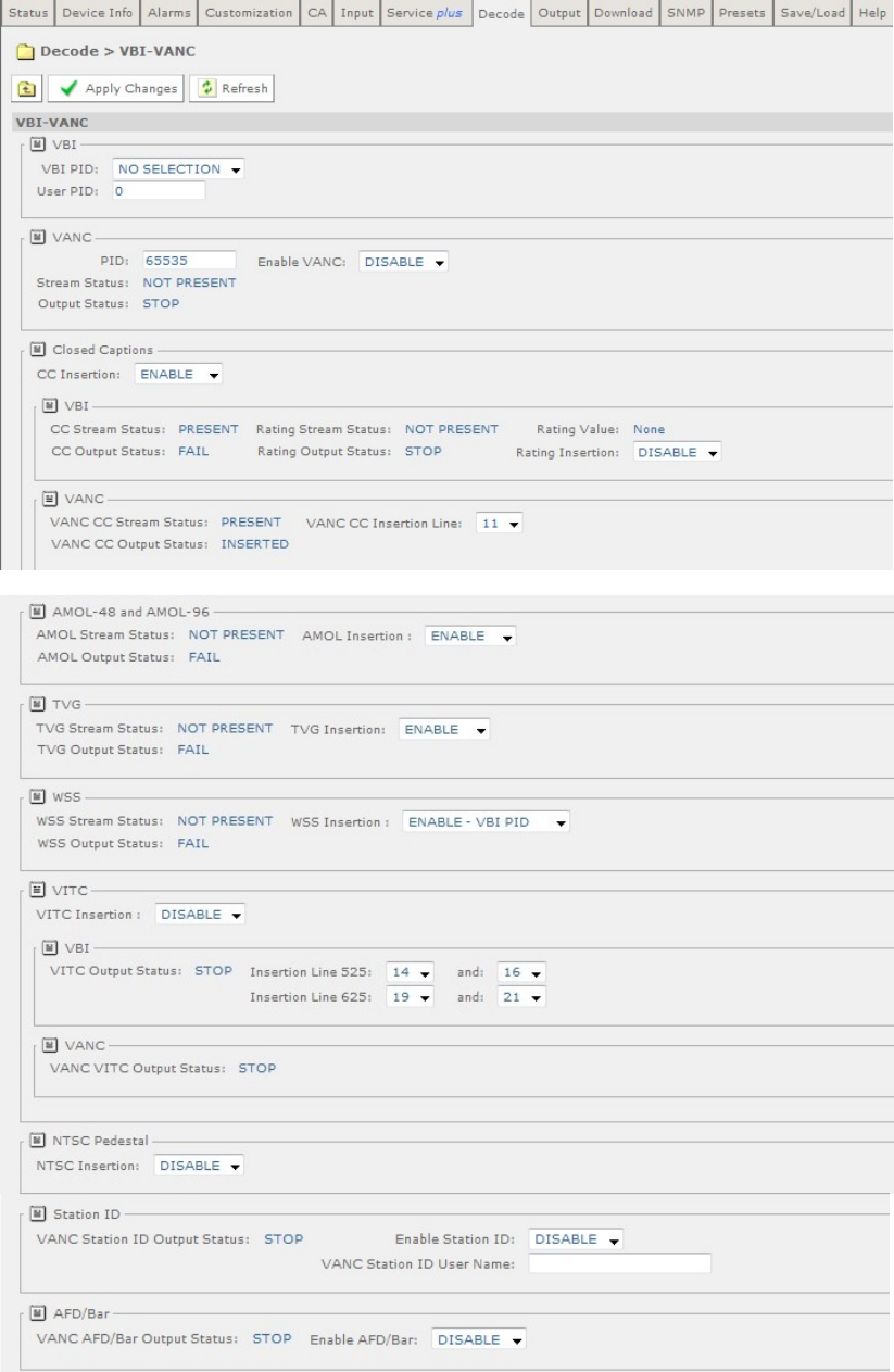
Chapter 5
Figure 5.29 Decode > VBI-VANC Web Page
EN/LZT 790 0005 R1A
5-31
Chapter 5
The following user-editable fields are displayed on this page.
User-editable fields in the VBI section:
• VBI PID - allows selection of the VBI PID from the service list via a drop-down
menu.
• User PID – allows user to input VBI PID.
User-editable fields in the VANC section:
• PID - allows input of PID.
• Enable VANC – allows enable/disable of VANC data from a drop-down menu.
User-editable fields in the Closed Captions section:
• CC Insertion - allows enable/disable of CC insertion from a drop-down menu.
• VBI Rating Insertion - allows enable/disable of rating information from a drop-
down menu.
• VANC CC Insertion Line – allows selection of insertion line from within the
vertical blanking interval from a drop-down menu.
User-editable fields from AMOL-48 and AMOL-96 section:
• AMOL (Automated Measurement of Lineups) Insertion - allows
enable/disable of AMOL insertion from a drop-down menu.
User-editable fields from Television Guide (TVG) section:
• TVG Insertion - allows enable/disable of TVG insertion from a drop-down menu.
Fields from WSS section:
• WSS (Widescreen Signalling) Insertion - allows enable/disable of WSS
insertion from a drop-down menu.
User-editable fields from VITC section:
• VITC (Vertical Interval Timecode) Insertion - allows enable/disable of VITC
insertion from a drop-down menu.
• VBI Insertion lines 525 and 625 - allows selection of insertion lines for VITC
from drop-down menus.
User-editable fields from NTSC Pedestal section:
• NTSC (National Television System Committee) Pedestal Insertion - allows
enable/disable of NTSC pedestal within the Vertical Blanking Interval from a
drop-down menu.
User-editable fields from Station ID section:
• Enable Station ID - allows enable/disable of Station ID from a drop-down menu.
EN/LZT 790 0005 R1A
5-32
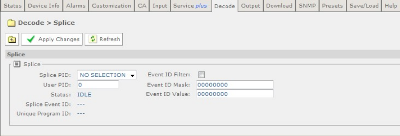
Chapter 5
• VANC Station ID User Name - allows input of Station ID user name.
User-editable fields from AFD/Bar section:
• Enable AFD/Bar - allows enable/disable of AFD/Bar from a drop-down menu.
Any changes which are made to the Decode > VBI VANC page may be confirmed
by selecting the Apply Changes button. Selecting the Refresh button will ensure
that the latest information is being displayed from the current values of the
equipment.
5.2.11.3 Decode > Splice
This page gives access to the splice operation parameters. To view this page, select
the Splice button from the Decode Web Page.
Figure 5.30 Decode > Splice Web Page
The following user-editable fields are displayed on this page.
• Splice PID - allows selection of the type of splice PID from a drop-down menu.
• User PID – allows input of user PID.
• Event ID Filter – checking this box enables splice event ID filtering.
• Event ID Mask – allows input of mask bits for event ID filter.
• Event ID Value – allows input of value bits for event ID filter.
Any changes which are made to the Decode > Splice page may be confirmed by
selecting the Apply Changes button. Selecting the Refresh button will ensure that
the latest information is being displayed from the current values of the equipment.
5.2.11.4 Decode > DVB-Subtitles
This page gives access to the Digital Video Broadcasting (DVB) subtitles
parameters. To view this page, select the DVB-Subtitles button from the Decode
page.
EN/LZT 790 0005 R1A
5-33
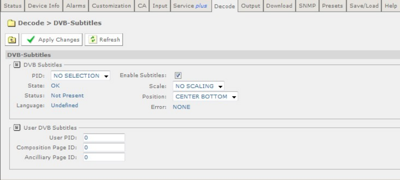
Chapter 5
Figure 5.31 Decode > DVB-Subtitles Web Page
The following fields, which may be edited by the user, are displayed on this page.
User-editable fields in the DVB Subtitles section:
• PID - allows selection of the type of PID from a drop-down menu.
• Enable Subtitles – checking this box allows the enabling of subtitles.
• Scale - allows selection of the level of scaling from a drop-down menu.
• Position - allows selection of the position of subtitles from a drop-down menu.
User-editable fields in the User DVB Subtitles section:
• User PID - allows input of user PID.
• Composition Page ID - allows input of composition Page ID.
• Ancillary Page ID - allows input of Ancillary Page ID.
Any changes which are made to the Decode > DVB Subtitles page may be
confirmed by selecting the Apply Changes button. Selecting the Refresh button will
ensure that the latest information is being displayed from the current values of the
equipment.
5.2.11.5 Decode > Teletext
This page gives access to the Teletext parameters. To view this page, select the
Teletext button from the Decode page.
EN/LZT 790 0005 R1A
5-34
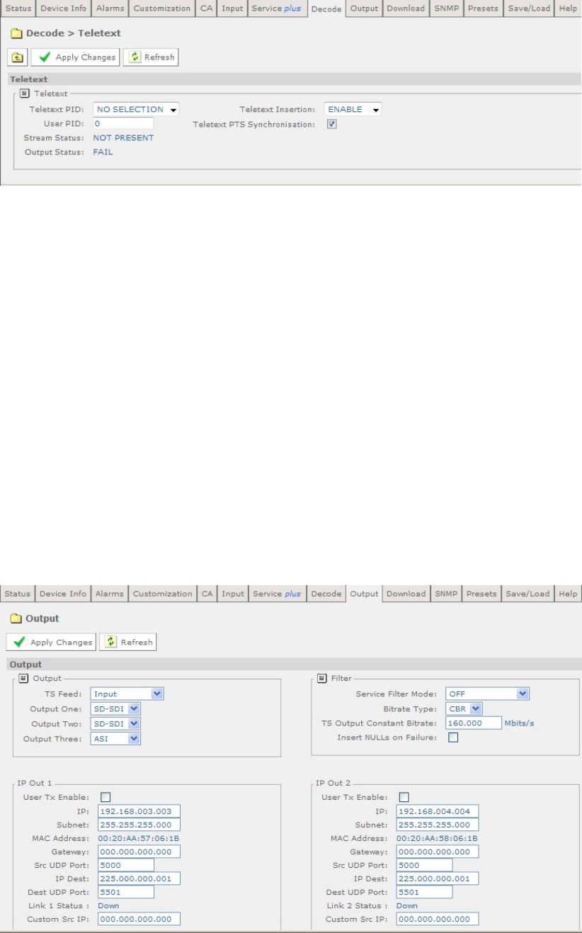
Chapter 5
Figure 5.32 Decode > Teletext Web Page
The following user-editable fields are displayed on this page.
• Teletext PID – allows selection of the type of Teletext PID from a drop-down
menu.
• Teletext Insertion – allows enable/disable of Teletext Insertion from a drop-
down menu.
• PTS Synchronisation – checking this box enables PTS Synchronisation.
Any changes which are made to the Decode > Teletext page may be confirmed
by selecting the Apply Changes button. Selecting the Refresh button will
ensure that the latest information is being displayed from the current values of
the equipment.
5.2.12 Output
This page gives access to the output parameters for the receiever. To view this
page, select the Output tab from the top of the current web Page.
EN/LZT 790 0005 R1A
5-35
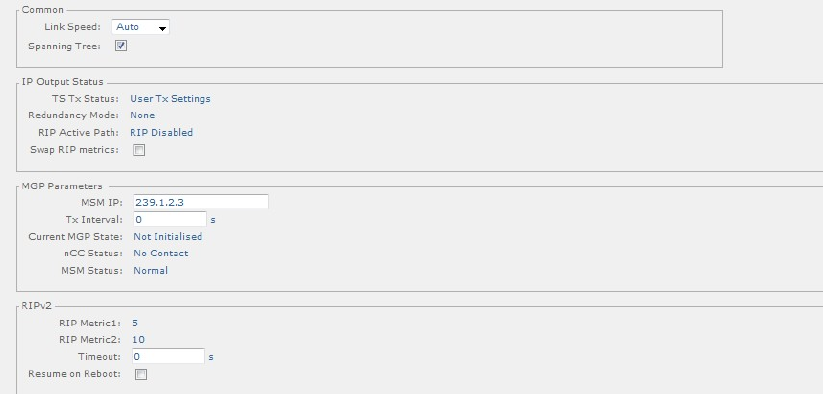
Chapter 5
Figure 5.33 Output Web Page
The following user-editable fields are displayed on this page.
User-editable fields in the Output section:
• TS (Transport Stream) Feed – allows selection of the type of transport stream
output from a drop-down menu.
• Output One/Two/Three – allows selection of the type of output from a drop-
down menu.
User-editable fields in the Filter Section:
• Service Filter Mode - allows selection of the Service Filter Mode from a drop-
down menu.
• Bitrate Type - allows selection of the Bitrate type from a drop-down menu.
• TS Output Constant Bitrate – allows the user to enter a value in Mbits/s.
Insert Nulls on Failure – checking this box will enure that CBR is maintained even
if the Transport stream is unlocked.
User-editable fields in the IP Out 1/IP Out 2 section:
• User TX Enable – checking this box enables the User Transmitter.
• IP – allows input of the IP address.
• Subnet – allows input of the Subnet mask address.
• Gateway - allows input of the gateway address.
• Src UDP (User Datagram Protocol) Port - allows input of the source UDP Port.
• IP Dest - allows input of the IP destination address.
• Dest UDP Port - allows input of the destination UDP port.
EN/LZT 790 0005 R1A
5-36
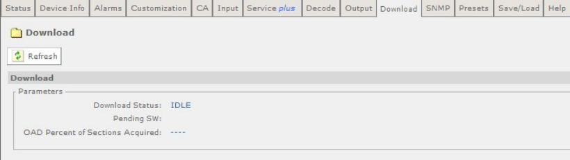
Chapter 5
• Custom Src IP - allows input of the Custom source IP.
User-editable fields in the Common section:
• Link Speed – allows the selection of the IP output card link configuration.
• Spanning Tree – checking this box enables the spanning tree protocol.
User-editable fields in the IP Output Status section:
• Swap RIP (Routing Information Protocol) Metrics - checking this box enables
this function.
User-editable fields in the MGP Parameters section:
• MSM IP - allows input of the MSM IP address.
• TX Interval - allows input of the Tx interval in seconds. A value of 0 means MGP
is disabled.
User-editable fields in the RIPv2 section:
• Timeout - allows input of the timeout in seconds. A value of 0 means RIP
updates are disabled.
• Resume on Reboot - checking this box enables RIP + TS resume on reboot.
Any changes which are made to the Output page may be confirmed by selecting the
Apply Changes button. Selecting the Refresh button will ensure that the latest
information is being displayed from the current values of the equipment.
5.2.13 Download
This page gives access to the over-air-download status of the receiver, if a
download is in progress. A percentage (%) complete of download is displayed. To
view this screen, select the Download tab from the current web page.
Figure 5.34 Download Web Page
There are no fields on this page which can be edited by the user. To ensure that the
most recent information is displayed, select the Refresh button.
Note: The unit should not be power cycled (turned off and on) during download.
EN/LZT 790 0005 R1A
5-37
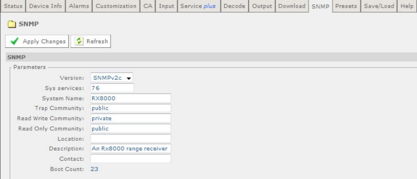
Chapter 5
5.2.14 SNMP
This page gives access to the Simple Network Management Protocol (SNMP)
parameters for the receiver. To view this page, select the SNMP Tab from the
current web page.
Figure 5.35 SNMP Web Page
The following user-editable fields are displayed on this page:
• Version - allows selection of the SNMP version from a drop-down menu.
• Sys Services – allows input of a value for MIB-2 services that this device
primarily offers (MIB-II RFC1213). See MIB-2 for definition.
• System Name – allows input of a MIB-2 sys name, which should be an
administratively-assigned name.
• Trap Community – allows input of type of trap community.
• Read Write Community - allows input of type of read write community.
• Read Only Community – allows input of type of read only community.
• Location – allows input of a MIB sys location which is the physical location of
this node.
• Description – allows input of a MIB sys description which should be a textual
description of the entity.
• Contact – allows input of a MIB sys contact which should be a textual
identification of the person to be contacted.
Any changes which are made to the SNMP page may be confirmed by selecting the
Apply Changes button. Selecting the Refresh button will ensure that the latest
information is being displayed from the current values of the equipment.
EN/LZT 790 0005 R1A
5-38
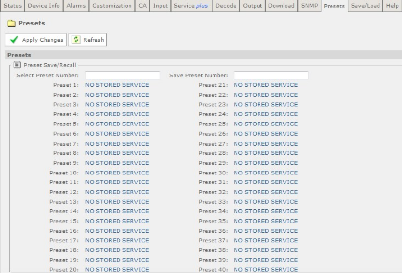
Chapter 5
5.2.15 Presets
This page gives access to a list of 40 preset configurations. This feature may be
used to store input (tuning) parameters in order that settings do not have to be re-
entered when changes are made. To view this page, select the Presets tab from the
top of the current web page.
Figure 5.36 Preset Web Page
The following user-editable fields are displayed on this page:
• Select Preset Number – allows the input of the number of the preset which is to
be selected. When a number is entered into this box, the tuning information and
service ID stored in that numbered preset will be loaded into the unit’s
configuration.
• Save Preset Number – allows the input of the number of the preset which is to
be saved. When a number is entered into this box, the tuning information and
service ID stored currently selected will be stored as that number preset. The
name will change from ‘NO STORED SERVICE’ to the name of the service.
Any changes which are made to the Presets page may be confirmed by selecting
the Apply Changes button. Selecting the Refresh button will ensure that the latest
information is being displayed from the current values of the equipment.
EN/LZT 790 0005 R1A
5-39
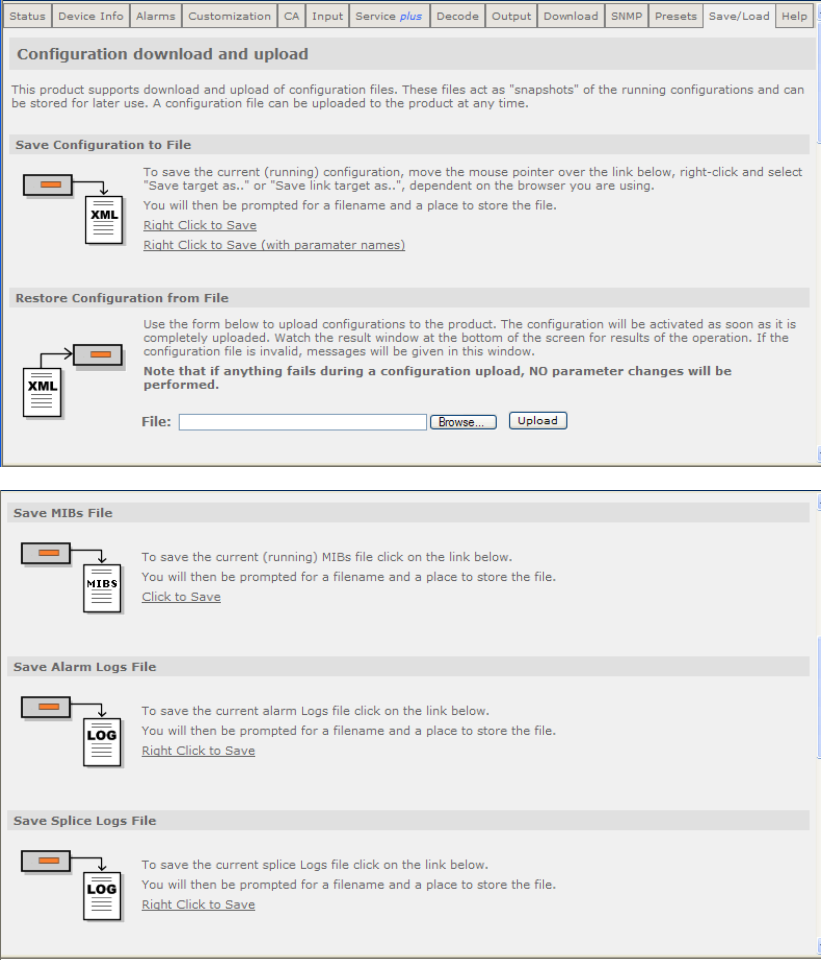
Chapter 5
5.2.16 Save/Load
This page gives access to a range of Configuration download and Upload facilities
which are supported by the receiver. To view this page, select the Save/Load tab
from the top of the current web page.
EN/LZT 790 0005 R1A
5-40
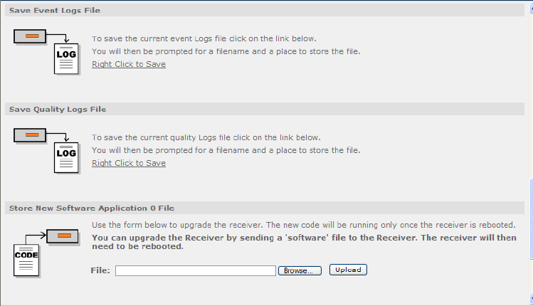
Chapter 5
Figure 5.37 Save/Load Web Page
Only a portion of the web page is shown in Figure 5.37. The facilities available from
this page are as follows:
• Save Configuration to File – allows the user to save the current receiver
configuration as an XML file. This may then be used as a back-up to preserve all
the settings entered on all the web pages so that you can upload them again
(using the Restore Configuration from File feature, described below), in the
event that the settings have been changed or lost. This feature also allows you
to quickly set up multiple equipments with the same settings, if required. The
option Right Click to Save should always be used. The option Right Click to
Save (with parameter names) is for development purposes only.
• Restore Configuration from File – allows the user to upload an XML file
defining the configuration of a receiver. This will normally be a configuration file
that has previously been saved (using the Save Configuration to File, described
above) from this or another similar equipment. This provides a quick and simple
method of restoring a unit to operation, provided that up-to-date back-ups are
maintained. The uploaded configuration will be actioned immediately, when
completed, provided that the file is valid. In the event of an invalid file being
uploaded, none of the equipment settings will be changed.
• Save MIBs File – allows the user to save the current running Management
Information Base (MIBs) file. A zip file is downloadable from the unit which
defines which variables should be monitored for SNMP purposes. Details of the
variables are not described in this document. For more detailed information on
SNMP remote control, contact Ericsson AB.
• Save Alarm Logs File - allows the user to save the current alarm logs file. It is
recommended that this is saved periodically, as it may be required in the event
of a fault occurring on the unit. Left-click on the link to display the log in the web
page (click the browser refresh button to return to the Web Browser Interface).
Right-click on the link and select the Save button in the displayed dialog to save
as a file.
EN/LZT 790 0005 R1A
5-41
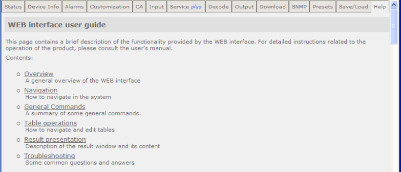
Chapter 5
EN/LZT 790 0005 R1A
5-42
• Save Splice Logs File - allows the user to save the current splice logs file. It is
recommended that these are saved periodically, as they may be required in the
event of a fault occurring on the unit. Left-click on the link to display the log in
the web page (click the browser refresh button to return to the Web Browser
Interface). Right-click on the link and select the Save button in the displayed
dialog to save as a file.
• Save Event Logs File - allows the user to save the current event logs file. It is
recommended that these are saved periodically, as they may be required in the
event of a fault occurring on the unit. Left-click on the link to display the log in
the web page (click the browser refresh button to return to the Web Browser
Interface). Right-click on the link and select the Save button in the displayed
dialog to save as a file.
• Save Quality Logs File - allows the user to save the current quality logs file. It
is recommended that these are saved periodically, as they may be required in
the event of a fault occurring on the unit. Left-click on the link to display the log
in the web page (click the browser refresh button to return to the Web Browser
Interface). Right-click on the link and select the Save button in the displayed
dialog to save as a file.
• Store New Software Application 0/1 File - allows the user to upgrade the
receiver. Click the Browse button to locate the application file and then click the
Upload button to upload the file to the receiver. The receiver must be rebooted
to run the new software; this can be done using the Reboot button on the
Device Info tab page.
5.2.17 Help
This page gives access to a Web Interface User guide which provides a brief
description of the interface functionality. To view this page, select the Help tab from
the top of the current web page.
Figure 5.38 Help Web Page
Select the appropriate heading listed on the web page for help with the associated
functions and features.

6 Options
Chapter 6
Contents
6.1 Hardware and Software Options ..........................................................6-3
6.1.1 DVB-S2 Input Card (RX8200/HWO/DVBS2)........................................6-5
6.1.2 8-VSB Input Card (RX83XX/HWO/8VSB) ............................................6-5
6.1.3 Gigabyte 100/1000Base T Ethernet (RX8XXX/HWO/IP/GIGE)............ 6-5
6.1.4 G.703 ATM Input Card (RX8XXX/HWO/G703) .................................... 6-5
6.1.5 MPEG-2 4:2:2 SD Decoding Card (RX82XX/HWO/MP2/422)..............6-5
6.1.6 MPEG-4 AVC 4:2:2 Decoding Card (RX8200/BAS/2).......................... 6-6
6.1.7 IP Output Card (RX8XXX/HWO/IP/OUT) .............................................6-6
6.1.8 SD Video and ASI Output Card (RX8200/HWO/SD)............................6-7
6.1.9 HD and SD Video and ASI Output Card (RX8200/HWO/HD/3G)......... 6-7
6.1.10 High Quality Down-conversion (RX8200/HWO/HQDCONV)................ 6-7
6.1.11 RS232 Low Speed Asynchronous Data and Remote Control
(RX8200/HWO/RS232) ........................................................................6-7
6.1.12 Balanced Audio Output Card (RX8200/HWO/BAL/AUD) ..................... 6-8
6.1.13 XLR Terminal Audio Break-Out Cable (RX8XXX/CABLE/XLR) ........... 6-8
6.1.14 Screw Terminal Audio Break-Out Cable (RX8XXX/CABLE/SCRTRM) 6-8
6.2 Software Enabled Options.................................................................... 6-8
6.2.1 DVB-S2 QPSK (RX8XXX/SWO/DVBS2/QPSK)................................... 6-8
6.2.2 DVB-S2 8PSK (RX8XXX/SWO/DVBS2/8PSK) ....................................6-8
6.2.3 DVB-S2 Low Symbol Rate (RX8XXX/SWO/DVBS2/LSYM)................. 6-8
6.2.4 MPEG-2 SD Decode (RX8XXX/SWO/MPEG2/SD)..............................6-9
6.2.5 MPEG-2 HD Decode (RX8XXX/SWO/MPEG2/HD) ............................. 6-9
6.2.6 MPEG-4 AVC SD Decode (RX8XXX/SWO/MPEG4/SD) .....................6-9
6.2.7 MPEG-4 AVC HD Decode (RX8XXX/SWO/MPEG4/HD).....................6-9
6.2.8 MPEG-2/4 AVC SD 4:2:0 Decode (RX8XXX/SWO/MP2/MP4/SD) ......6-9
6.2.9 MPEG-2/4 AVC HD 4:2:0 Decode (RX8XXX/SWO/MP2/MP4/SD/HD) 6-9
6.2.10 Single-Service Filtering (RX8XXX/SWO/SING/SERVFILT)................ 6-10
6.2.10.1 PSI/SI Insertion................................................................................... 6-10
6.2.10.2 PID Remapping ..................................................................................6-10
6.2.11 Multi-Service Filtering (RX8XXX/SWO/MULTI/SERVFILT)................6-11
6.2.12 High-Speed Data Output (RX8XXX/SWO/IP/DATA) ..........................6-11
6.2.13 Password Protection of Web Browser (RX8XXX/SWO/PW) .............. 6-11
6.2.14 IP Transport Stream Output (RX8XXX/SWO/IP/OUT) ....................... 6-11
6.2.15 Director (RX8XXX/SWO/DIR5)........................................................... 6-12
6.2.16 Director Multi-Service Decryption (RX8XXX/SWO/DIR5/MSD)..........6-12
6.2.17 Multi-Service CAM Decryption (RX8XXX/SWO/MSD)........................6-12
6.2.18 Serial Data Interface (RX8XXX/SWO/SDI)......................................... 6-12
EN/LZT 790 0005 R1A
6-1
Chapter 6
EN/LZT 790 0005 R1A
6-2
6.2.19 Dolby Digital Decode (RX8XXX/SWO/AC3)....................................... 6-12
6.2.20 AAC Audio Decode (RX8XXX/SWO/AAC)......................................... 6-12
6.2.21 DVB-S2 16APSK (RX8XXX/SWO/DVBS2/16APSK) ......................... 6-13
6.2.22 Null Packet Detection Redundancy Switching
(RX8XXX/SWO/DVBS2/NULL) .......................................................... 6-13
6.2.23 DVB Common Interface (RX8XXX/SWO/CI)...................................... 6-13
6.2.24 BISS CA (RX8XXX/SWO/BISS)......................................................... 6-13
6.2.25 BISS Multi-Service CA (RX8XXX/SWO/BISS/MSD) .......................... 6-13
6.2.26 SMPTE 2022 Pro-MPEG FEC (RX8200/SWO/IP/PROMPEG).......... 6-13
6.2.27 MPEG-2 SD 4:2:2 Decoding (RX8200/SWO/MP2/SD/422)............... 6-14
6.2.28 MPEG-2 HD 4:2:2 Decoding (RX8200/SWO/MP2/HD/422)............... 6-14
6.2.29 MPEG-4 SD 4:2:2 Decoding (RX8200/SWO/MP4/SD/422)............... 6-14
6.2.30 MPEG-4 HD 4:2:2 Decoding (RX8200/SWO/MP4/HD/422)............... 6-14
6.2.31 Down-Conversion (RX8200/SWO/DCONV)....................................... 6-14
6.2.32 Up-Conversion (RX8200/SWO/UPCONV)......................................... 6-14
6.2.33 Cross-Conversion (RX8200/SWO/XCONV)....................................... 6-14
6.2.34 Framesync (RX8200/SWO/FSYNC) .................................................. 6-15
6.2.35 4 x Audio Capability (RX8200/SWO/4AUD)....................................... 6-15
6.2.36 Low Latency Decode (RX8200/SWO/LDELAY)................................. 6-15
List of Figures
Figure 6.1: The Protocol Stack ............................................................................... 6-6
Figure 6.2: Building the Ethernet Frame................................................................. 6-7
List of Tables
Table 6.1 Hardware and Software Options for the RX8000 Series Receivers..... 6-3

Chapter 6
6.1 Hardware and Software Options
These options require extra hardware to be fitted to the unit, or, in the case of
software, extra licenses to be purchased. See Table 6.1 for a list of available
options. Contact the Customer Services Helpdesk for details (see Preliminary
Pages).
z = Option B = Supplied with Base Model
Table 6.1 Hardware and Software Options for the RX8000 Series Receivers
RX8200
RX8310
RX8315
RX8320
RX8330
Option Number Description
Hardware Options
z B B B RX8200/HWO/DVBS2 DVB-S2 Input Card
B RX8320/HWO/8VSB 8-VSB Input Card
z RX8XXX/HWO/IP/GIGE Gigabyte 100/1000BaseT Ethernet
z RX8XXX/HWO/G703 G.703 ATM Input Card
z RX8XXX/HWO/MP2/422 MPEG-2 4:2:2 Decode Card
B RX8200/BAS/2 MPEG-4 4:2:2 Decode Capable RX8200
z z z z RX8XXX/HWO/IP/OUT IP Transport Stream Output Card
z RX8200/HWO/SD SD Video Input and ASI Output Card
z RX8200/HWO/HD/3G HD and SD Input and ASI Output Card
z RX8200/HWO/BAL/AUD Balance Audio Output
z RX8200/HWO/RS232 RS232 Low Speed Asynchronous Data
and Remote Control
z RX8200/HWO/HQDCONV High Quality Down-conversion
z z z z z RX8XXX/CABLE/XLR XLR Terminal Audio Break-out Cable
z z z z z RX8XXX/CABLE/SCRTRM Screw Terminal Audio Break-out Cable
Software Options
z z z z RX8XXX/SWO/DVBS2/QPSK DVB-S2 QPSK
z z z z RX8XXX/SWO/DVBS2/8PSK DVB-S2 8PSK
z z z z RX8XXX/SWO/DVBS2/LSYM DVB-S2 Low Symbol Rate
z z z B z RX8XXX/SWO/MPEG2/SD MPEG-2 SD 4:2:0 Decoding
z z z B z RX8XXX/SWO/MPEG2/HD MPEG-2 HD 4:2:0 Decoding
z RX8XXX/SWO/MPEG4/SD MPEG-4 SD 4:2:0 Decoding
z RX8XXX/SWO/MPEG4/HD MPEG-4 HD 4:2:0 Decoding
EN/LZT 790 0005 R1A
6-3

Chapter 6
RX8200
RX8310
RX8315
RX8320
RX8330
Option Number Description
z z z z RX8XXX/SWO/MP2/MP4/SD MPEG-2/4 AVC SD 4:2:0 Decoding
z z z z RX8XXX/SWO/MP2/MP4/SD/HD MPEG-2/4 AVC HD 4:2:0 Decoding
z z z z z RX8XXX/SWO/SING/SERVFILT Single Service Filtering
z z z z z RX8XXX/SWO/MULT/SERVFILT Multi-Service Filtering
z z z z RX8XXX/SWO/IP/DATA High Speed Data Output
z z z z z RX8XXX/SWO/PW Password Protection Web Browser
z RX8XXX/SWO/IP/OUT IP Transport Stream Out
z B B B RX8XXX/SWO/DIR5 Director
z z z RX8XXX/SWO/DIR5/MSD Director Multi-Service Decryption
z z z RX8XXX/SWO/MSD Multi-Service CAM Decryption
B B RX8XXX/SWO/SDI SDI Digital Video Out Disable
z z z B z RX8XXX/SWO/AC3 Dolby Digital Decode
z z z z RX8XXX/SWO/AAC AAC Decode
z z z z RX8XXX/SWO/DVBS2/16APSK DVB-S2 16 APSK
z z z z z RX8XXX/SWO/DVBS2/NULL Null Packet Detection Redundancy Switch
z B B RX8XXX/SWO/CI DVB Common Interface
z z RX8XXX/SWO/BISS BISS Modes 1 and E
z z RX8XXX/SWO/BISS/MSD BISS Modes 1 and E Multi-Service Decrypt
z RX8200/SWO/IP/PROMPEG SMPTE 2022 Pro-MPEG FEC
z RX8200/SWO/HDSDI/3G MPEG-4 HD 4:2:2 1080p 50/60 Decoding
z RX8200/SWO/MP2/SD/422 MPEG-2 SD 4:2:2 Decoding
z RX8200/SWO/MP2/HD/422 MPEG-2 HD 4:2:2 Decoding
z RX8200/SWO/MP4/SD/422 MPEG-4 SD 4:2:2 Decoding
z RX8200/SWO/MP4/HD/422 MPEG-4 HD 4:2:2 Decoding
z RX8200/SWO/DCONV Down-conversion
z RX8200/SWO/UPCONV Up-conversion
z RX8200/SWO/XCONV Cross-conversion
z RX8200/SWO/FSYNC Frame Sync Input
z RX8200/SWO/4AUD 4 x Audio Capacity
z RX8200/SWO/LDELAY Low Latency Decode
EN/LZT 790 0005 R1A
6-4

Chapter 6
6.1.1 DVB-S2 Input Card (RX8200/HWO/DVBS2)
This option is only available for the RX8200 Receiver and is fitted as standard to the
base models of RX8310, 8315 and 8330.
With accompanying software options, the DVB-S2 Input card supports DVB-S,
QPSK demodulation and DVB-S2, QPSK and 8PSK demodulation.
RX8200/HWO/DVBS2 provides four L-band inputs.
Cautions!
The receiver provides DC power (refer to Chapter 3, Operating the Equipment
Locally) via the active L-Band input connector to drive an LNB (Low-Noise Block
Down-Converter). Do not connect equipment other than an LNB to this connector.
Failure to do this may result in damage to the external equipment.
The F-type Connector is not suitable for repeated connection and disconnection.
When intended for use in this way, fit a sacrificial connector and connect to it.
6.1.2 8-VSB Input Card (RX83XX/HWO/8VSB)
This option is only available for the RX8320 ATSC Broadcast Receiver.
The 8-VSB Input card supports ATSC demodulation.
6.1.3 Gigabyte 100/1000Base T Ethernet (RX8XXX/HWO/IP/GIGE)
This option is available for the RX8320 ATSC Broadcast Receiver and the RX8200,
8315, 8320 and 8330 DVB Receivers.
The 100/1000Base T Input card supports an MPEG transport stream over IP and
SMPT 2022 Pro-MPEG FEC with license key. Two 100/1000 Base T inputs are
provided and this system also has a very low latency level.
6.1.4 G.703 ATM Input Card (RX8XXX/HWO/G703)
This option is available for the RX8320 ATSC Broadcast Receiver and the RX8315,
8320 and 8330 DVB Receivers.
The G.703 ATM input card provides E3 or DS-3 inputs and offers a choice of 34 or
45 Mbps rates.
6.1.5 MPEG-2 4:2:2 SD Decoding Card (RX82XX/HWO/MP2/422)
This option is only available for the RX8200 DVB Receiver.
EN/LZT 790 0005 R1A
6-5
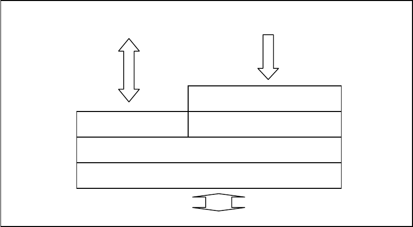
Chapter 6
The MPEG-2 4:2:2 SD Decoding Card provides 4:2:2 video decoding facilities.
6.1.6 MPEG-4 AVC 4:2:2 Decoding Card (RX8200/BAS/2)
This option is only available for the RX8200 DVB Receiver.
RX8200/BAS/2 is equipped with MPEG-4 4:2:2 decoding functionality. This function
is dormant and is enabled with additional software options.
6.1.7 IP Output Card (RX8XXX/HWO/IP/OUT)
This option is available for the RX8200, 8310, 8315 and 8330 DVB Receivers.
The IP Output card supports 1000BaseT Ethernet transmission of encapsulated
transport stream.
The mapping of MPEG-2 TS packets into IP data frames is done according to the
protocol stack shown in Figure 6.1. The figure shows the Protocol Stack in use when
mapping MPEG-2 into IP frames and Ethernet.
Figure 6.1: The Protocol Stack
The MPEG-2/DVB layer is specified in ISO/IEC IS 13818 – Generic Coding of
Moving Pictures and Associated Audio. The UDP layer is compliant with RFC768 –
User Datagram Protocol. A configurable number of 188 byte MPEG-2 TS packets
are mapped straight into an UDP frame with no additional overhead. The MTU for
Ethernet is usually 1500 bytes. This limits the number of MPEG-2 TS packets per
UDP frame to lie within one to seven.
The IP layer is according to RFC791 – Internet Protocol Specification.
Link layer – 1000BaseT Ethernet
Transport layer - IP
TCP/UDP UDP – User Datagram Protocol
MPEG-2/DVB layer
MPEG-2 Transport Stream
(Multi-Program Transport
Stream or Single-Program
Transport Stream)
Control traffic for in-
band management
(telnet, http, snmp)
EN/LZT 790 0005 R1A
6-6

Chapter 6
Figure 6.2 shows a more detailed picture of the MPEG-2 data transfer. TS-packets
are mapped in a datagram, using User Data Protocol (UDP), Internet Protocol (IP)
and Ethernet.
Figure 6.2: Building the Ethernet Frame
…
Information 14H
Information
Information
20H
8H
188 188 TS packets (1 to7)
UDP datagram
IP datagram
Ethernet frame
6.1.8 SD Video and ASI Output Card (RX8200/HWO/SD)
This option is only available for the RX8200 Receiver.
The SD Video and ASI Output card provides two composite video outputs and two
switchable ASI/SDI outputs.
6.1.9 HD and SD Video and ASI Output Card (RX8200/HWO/HD/3G)
This option is only available for the RX8200 Receiver.
The HD and SD Video and ASI Output card provides one composite video output,
one RGB/YPrPb analog video output and three switchable ASI/SDI/HD-SDI outputs.
6.1.10 High Quality Down-conversion (RX8200/HWO/HQDCONV)
This option is only available for the RX8200 Receiver.
This option provides down-conversion of decoded HD video to SD resolution. Native
HD and SD video outputs are available simultaneously. This option provides grade 1
quality down-converted SD video.
6.1.11 RS232 Low Speed Asynchronous Data and Remote Control
(RX8200/HWO/RS232)
This option is only available for RX8200 Receiver.
This option provides RS232 low speed asynchronous data output and RS232
remote control capability.
EN/LZT 790 0005 R1A
6-7
Chapter 6
6.1.12 Balanced Audio Output Card (RX8200/HWO/BAL/AUD)
This option is only available for the RX8200 Receiver.
The Balanced Audio Output card provides two stereo pairs of balanced analog and
digital outputs. If four stereo pairs are required, two cards should be ordered.
6.1.13 XLR Terminal Audio Break-Out Cable (RX8XXX/CABLE/XLR)
This option is available for the RX8200, 8310, 8315, 8320 and 8330 Receivers.
The XLR Terminal Audio Break-Out Cable provides XLR terminal connections for
analog and digital audio output and one stereo pair per cable via two screw terminal
connectors.
6.1.14 Screw Terminal Audio Break-Out Cable (RX8XXX/CABLE/SCRTRM)
This option is available for the RX8200, 8310, 8315, 8320 and 8330 Receivers.
The Screw Terminal Audio Break-Out Cable provides screw terminal connections for
analog and digital audio output and one stereo pair per cable via two screw terminal
connectors.
6.2 Software Enabled Options
These options may be enabled through software license keys. Contact the
Customer Services Helpdesk for details (see Preliminary Pages).
6.2.1 DVB-S2 QPSK (RX8XXX/SWO/DVBS2/QPSK)
This option is available for the RX8200, 8310, 8315 and 8330 Receivers.
The DVB-S2 QPSK software option provides DVB-S2 QPSK capability to the
DVB-S2 input card.
6.2.2 DVB-S2 8PSK (RX8XXX/SWO/DVBS2/8PSK)
This option is available for the RX8200, 8310, 8315 and 8330 Receivers.
The DVB-S2 8PSK software option provides DVB-S2 QPSK and 8PSK capability to
the DVB-S2 input card.
6.2.3 DVB-S2 Low Symbol Rate (RX8XXX/SWO/DVBS2/LSYM)
This option is available for the RX8200, 8310, 8315 and 8330 Receivers.
EN/LZT 790 0005 R1A
6-8
Chapter 6
The DVB-S2 Low Symbol Rate software option enables a DVB-S2 symbol rate of
1-5 Msym/s.
6.2.4 MPEG-2 SD Decode (RX8XXX/SWO/MPEG2/SD)
This option is available for the RX8200, 8310, 8315 and 8330 Receivers.
This option enables MPEG-2 SD 4:2:0 decoding.
6.2.5 MPEG-2 HD Decode (RX8XXX/SWO/MPEG2/HD)
This option is available for the RX8200, 8310, 8315 and 8330 Receivers.
This option enables MPEG-2 HD and MPEG-2 SD 4:2:0 decoding.
6.2.6 MPEG-4 AVC SD Decode (RX8XXX/SWO/MPEG4/SD)
This option is only available for the RX8320 ATSC Receiver.
This option enables MPEG-4 AVC SD MP/HP@L3 video decoding.
6.2.7 MPEG-4 AVC HD Decode (RX8XXX/SWO/MPEG4/HD)
This option is only available for the RX8320 ATSC Receiver.
This option enables MPEG-4 AVC HD video to be down-converted and presented
as SD on the CVBS output. MPEG-4 AVC SD MP/HP@L4 video decoding is also
supported.
6.2.8 MPEG-2/4 AVC SD 4:2:0 Decode (RX8XXX/SWO/MP2/MP4/SD)
This option is available for the RX8200 (fitted as standard on SWO/IP/OUT and
SWO/SDI), 8310, 8315 and 8330 Receivers.
This option enables MPEG-2 and MPEG-4 AVC SD 4:2:0 video decoding.
6.2.9 MPEG-2/4 AVC HD 4:2:0 Decode (RX8XXX/SWO/MP2/MP4/SD/HD)
This option is available for the RX8200, 8310, 8315 and 8330 Receivers.
This option enables MPEG-2 SD and HD and MPEG-4 AVC SD and HD 4:2:0 video
decoding.
EN/LZT 790 0005 R1A
6-9
Chapter 6
6.2.10 Single-Service Filtering (RX8XXX/SWO/SING/SERVFILT)
This option is available for the RX8200, 8310, 8315, 8320 and 8330 Receivers.
This option filters a complete service from a Multiple Program Transport Stream
(MPTS) source and generates an Single Program Transport Stream (SPTS). When
the Output tab/Filter Group/Service Filter Mode/Single Service option is selected the
Filter column of the ServicePlus web page is enabled (see 5.2.10 Service Plus web
page description).
The service may be selected using the Service Program Number and the selection
will be retained during rebooting operations. All components of the service are
automatically filtered and available at the output. If a different service is selected, the
new components will replace those of the previously selected service.
If the RX8XXX can decrypt the source TS, the output of the filtered service may be
selected for descrambling.
The output bit rate, which is selected by the user, may be constant (by inserting
NULL packets) or variable (plus the increment due to the PSI SI insertion).
In Constant mode, if overrate protection is ticked the unit will not clip any services
which ‘over rate’ the selected bit rate. The unit also has the option to insert nulls on
failure. Both of these functions are available from the Output tab of the web control.
6.2.10.1 PSI/SI Insertion
When the input to the receiver is a DVB TS, the PAT and the SDT-Actual are
regenerated. The PMT regeneration is forced in case the PID is shared by more
than a PID. If this is not the case, PMTs will be passed through as will CATs, NIT-
Actual, TDT and TOT PIDs.
If the input to the receiver is an ATSC TS, only the PAT will be regenerated. THE
VCT PID will be passed through as will PMTs, CAT,TDT and TOT PIDs.
6.2.10.2 PID Remapping
This feature allows the filtering of a service from a Multiple Program Transport
Stream (MPTS) source and generates a custom Single Program Transport Stream
(SPTS) with components selected from those included in the service. These
components and the PMT PID can be remapped.
This service may be initiated by selecting the Output tab from the top of the current
web screen then selecting Filter Group>Service Filter Mode>REMAP. This enables
the REMAP column of the Serviceplus table. The required service is selected by
service program number and will be retained after rebooting. To select the
components which are to be filtered and remapped, the Details link should be
selected. Configuration is by component type or Input PID and relies on a best-
match algorithm where the most significant parameter is the component type. This
configuration is only available via the web interface.
EN/LZT 790 0005 R1A
6-10
Chapter 6
The output bit rate, which is selected by the user, may be constant (by inserting
NULL packets) or variable (plus the increment due to the PSI SI insertion).
6.2.11 Multi-Service Filtering (RX8XXX/SWO/MULTI/SERVFILT)
This option is available for the RX8200, 8310, 8315, 8320 and 8330 Receivers.
This option enables the filtering of services within a Multiple Program Transport
Stream (MPTS) and provides a single CBR MPTS output.
This feature generates a custom MPTS by filtering services from a source MPTS.
This service may be initiated by selecting the Output tab from the web browser then
selecting Filter Mode>MULTI SERVICE. This enables the FILTER column of the
Serviceplus table. From this page, the user is able to select up to 22 services to be
filtered. All components of the selected service will be filtered and presented at the
output MPTS.
The output bit rate, which is selected by the user, may be constant (by inserting
NULL packets) or variable (plus the increment due to the PSI SI insertion).
In Constant mode, if overrate protection is ticked the unit will not clip any services
which ‘over rate’ the selected bit rate. The unit also has the option to insert nulls on
failure. Both of these functions are available from the Output tab of the web control.
6.2.12 High-Speed Data Output (RX8XXX/SWO/IP/DATA)
This option is available for the RX8200, 8310, 8315 and 8330 Receivers.
This option enables MPE-based data de-encapsulation of IP data and requires the
IP TS Output option (RX8XXX/HWO/IP/OUT) to be fitted.
6.2.13 Password Protection of Web Browser (RX8XXX/SWO/PW)
This option is available for the RX8200, 8310, 8315, 8320 and 8330 Receivers.
This option protects the web browser from malicious or accidental changes, only
allowing access via a windows username and password screen.
Note: Default username = username. Default password = password.
6.2.14 IP Transport Stream Output (RX8XXX/SWO/IP/OUT)
This option is only available for the RX8320 ATSC Receiver.
This option enables the IP transport stream output and encapsulation of the
transport stream into multicast. There are two Gigabit Ethernet RJ-45 interfaces
always fitted which are enabled with a feature key.
EN/LZT 790 0005 R1A
6-11
Chapter 6
Note: This option is available to all other units by selecting
RX8XXX/HWO/IP/OUT. Note this will also order an IP Output Card.
6.2.15 Director (RX8XXX/SWO/DIR5)
This option is only available for the RX8200 Receiver.
This option provides Director Conditional Access (CA), over-air control and over-air
software downloads.
This license provides only single service decryption.
6.2.16 Director Multi-Service Decryption (RX8XXX/SWO/DIR5/MSD)
This option is available for the RX8200, 8310 and 8330 Receivers.
This option provides multi-service decryption for Director.
6.2.17 Multi-Service CAM Decryption (RX8XXX/SWO/MSD)
This option is available for the RX8315 and 8330 Receivers.
This option enables the decryption of multiple services via professional CAMs and
allows the simultaneous decryption of up to10 services or 24 PIDs. This limit is
imposed by the receiver but the actual limit is the lower limit between the receiver
limit and that of the inserted CAM.
6.2.18 Serial Data Interface (RX8XXX/SWO/SDI)
This option is fitted as standard on the base models of RX8200 and 8330 Receivers.
This option allows the output of baseband audio/video and data as digital serial data
as per SMPTE-259M.
6.2.19 Dolby Digital Decode (RX8XXX/SWO/AC3)
This option is available for the RX8200, 8310, 8315 and 8330 Receivers.
This option enables decoding or pass-through of Dolby Digital Audio and also
provides two x 5.1 decode and down-mix to 2.0 (stereo) and two x 2.0/5.1 pass-
through compressed and embedded in (HD) SDI.
6.2.20 AAC Audio Decode (RX8XXX/SWO/AAC)
This option is available for the RX8200, 8310, 8315 and 8330 Receivers.
EN/LZT 790 0005 R1A
6-12
Chapter 6
This option enables two x AAC-LC and HE-AAC decoding.
6.2.21 DVB-S2 16APSK (RX8XXX/SWO/DVBS2/16APSK)
This option is available for the RX8310, 8315 and 8330 Receivers.
This option adds DVB-S2 QPSK, 8PSK and 16APSK capability to the DVB-S2 Input
Option Card.
6.2.22 Null Packet Detection Redundancy Switching
(RX8XXX/SWO/DVBS2/NULL)
This option is available for the RX8200, 8310, 8315, 8320 and 8330 Receivers.
This option provides redundancy switching from a primary to secondary input when
triggered by the presence of null packets in the incoming stream. The user is able to
define the percentage of null packets at which the switch is triggered.
6.2.23 DVB Common Interface (RX8XXX/SWO/CI)
This option is only available for the RX8200 Receiver.
This option enables support for conditional access modules.
6.2.24 BISS CA (RX8XXX/SWO/BISS)
This option is available for the RX8200 and RX8330 Receivers.
This option enables descrambling for BISS modes 1 and E.
6.2.25 BISS Multi-Service CA (RX8XXX/SWO/BISS/MSD)
This option is available for the RX8200 and RX8330 Receivers.
This option enables multi-service decryption for BISS modes 1 and E.
6.2.26 SMPTE 2022 Pro-MPEG FEC (RX8200/SWO/IP/PROMPEG)
This option is only available for the RX8200 Receiver.
This option enables SMPTE 2022 Pro-MPEG FEC capability and requires the
installation of an IP input card.
EN/LZT 790 0005 R1A
6-13
Chapter 6
6.2.27 MPEG-2 SD 4:2:2 Decoding (RX8200/SWO/MP2/SD/422)
This option is only available for the RX8200 Receiver.
This option enables MPEG-2 SD 4:2:2 Decoding and requires the installation of the
MPEG-2 SD 4:2:2 hardware option card.
6.2.28 MPEG-2 HD 4:2:2 Decoding (RX8200/SWO/MP2/HD/422)
This option is only available for the RX8200 Receiver.
This option enables MPEG-2 HD 4:2:2 Decoding and requires the installation of the
MPEG-2 SD 4:2:2 hardware option card.
6.2.29 MPEG-4 SD 4:2:2 Decoding (RX8200/SWO/MP4/SD/422)
This option is only available for the RX8200 Receiver.
This option enables MPEG-2 and MPEG-4 SD 4:2:2 Decoding and requires the
RX8200/BAS/2 MPEG-4 4:2:2 capable base unit.
6.2.30 MPEG-4 HD 4:2:2 Decoding (RX8200/SWO/MP4/HD/422)
This option is only available for the RX8200 Receiver.
This option enables MPEG-2 and MPEG-4 HD 4:2:2 Decoding and requires the
RX8200/BAS/2 MPEG-4 4:2:2 capable base unit.
6.2.31 Down-Conversion (RX8200/SWO/DCONV)
This option is only available for the RX8200 Receiver.
This option enables the down-conversion of HD to SD and allows the simultaneous
presentation of HD and SD on video output interfaces.
6.2.32 Up-Conversion (RX8200/SWO/UPCONV)
This option is only available for the RX8200 Receiver.
This option enables the up-conversion of SD to HD and allows the non-simultaneous
up-conversion to 720p or 1080i resolution.
6.2.33 Cross-Conversion (RX8200/SWO/XCONV)
This option is only available for the RX8200 Receiver.
EN/LZT 790 0005 R1A
6-14
Chapter 6
This option enables the conversion of HD video from 720p to 1080i or from 1080i to
720p.
6.2.34 Framesync (RX8200/SWO/FSYNC)
This option is only available for the RX8200 Receiver.
This option enables the framesync input, which allows the unit to synchronise the
video/audio playout of the unit to an external clock so that all synchronized
equipment will output A/V frames at the same time.
6.2.35 4 x Audio Capability (RX8200/SWO/4AUD)
This option is only available for the RX8200 Receiver.
This option enables up to 6 decodes (2 ‘basic’ and 4 ‘advanced’). The 4 extra
‘advanced’ audios are compatible with MPEG-1 Layer II, Dolby Digital, AAC, Dolby
E and linear audio. With this option you can embed up to 6 channels of audio into
the (HD)SDI video output. If four stereo pairs of physical audio interfaces are
required, two audio output cards will need to be installed.
6.2.36 Low Latency Decode (RX8200/SWO/LDELAY)
This option is only available for the RX8200 Receiver.
This option enables low latency video decode and will operate on MPEG-1 Layer II
audio only. With this license, low delay modes are available which cut down the
decode unit end-to-end delay within the unit. These lower delay modes will not work
under all transport conditions and should be used under consultation with Ericsson.
EN/LZT 790 0005 R1A
6-15
Chapter 6
EN/LZT 790 0005 R1A
6-16
BLANK

7 Preventive Maintenance and Fault-Finding
Chapter 7
Contents
7.1 Introduction...........................................................................................7-3
7.2 Preventive Maintenance ....................................................................... 7-3
7.2.1 Routing Inspection................................................................................7-3
7.2.1.1 Cooling Fans ........................................................................................7-3
7.2.2 Cleaning ...............................................................................................7-3
7.2.3 Servicing...............................................................................................7-3
7.2.3.1 Conditions Requiring Servicing ............................................................7-3
7.2.3.2 Replacement Parts ...............................................................................7-4
7.2.3.3 Checks on Completion of Servicing...................................................... 7-4
7.3 Maintenance and Support Services...................................................... 7-4
7.3.1 Introduction...........................................................................................7-4
7.3.2 Warranty ............................................................................................... 7-4
7.3.3 Levels of Continuing Ericsson Service Support.................................... 7-5
7.4 Fault-finding..........................................................................................7-5
7.4.1 General.................................................................................................7-5
7.4.2 System Defaults ...................................................................................7-5
7.4.3 Preliminary Investigations..................................................................... 7-6
7.4.4 AC Fuse Replacement .........................................................................7-6
7.4.5 Power Supply Problems .......................................................................7-7
7.4.6 Summary Status LED Unlit................................................................... 7-8
7.4.7 Fan(s) Not Working/Overheating.......................................................... 7-8
7.4.8 Input Card Failure.................................................................................7-9
7.5 Disposal................................................................................................7-9
7.5.1 Moulded Plugs......................................................................................7-9
7.5.2 Equipment ..........................................................................................7-10
List of Figures
Figure 7.1 Fuse Carrier......................................................................................... 7-7
List of Tables
Table 7.1 Fuse Information..................................................................................7-6
Table 7.2 Summary Status LED Unlit Fault-finding ..............................................7-8
Table 7.3 Fans Not Working/Overheating ............................................................ 7-9
Table 7.4 Input Card Fault-finding ........................................................................ 7-9
EN/LZT 790 0005 R1A
7-1
Chapter 7
EN/LZT 790 0005 R1A
7-2
BLANK

Chapter 7
7.1 Introduction
This chapter provides the schedules and instructions, where applicable, for routine
inspection, cleaning and maintenance of the equipment which should be performed
by an operator. There are also some basic fault-finding procedures to follow in the
event of a suspected unit failure
7.2 Preventive Maintenance
7.2.1 Routing Inspection
7.2.1.1 Cooling Fans
There are no routine checks associated with this unit other than to ensure that the
unit is adequately cooled. The fans should be on continuously. This unit must never
be operated unless the cooling fans are working. Check periodically.
Caution!
The fan contained within this unit is not fitted with an insect/dust filter. Pay particular
attention to the environment in which it is going to be used.
Failure to ensure a free flow of air around the unit may cause overheating.
7.2.2 Cleaning
Unplug the unit from the power supply outlet before cleaning. Do not use liquid or
aerosol cleaners. Use a damp cloth for cleaning the exterior of the unit.
7.2.3 Servicing
7.2.3.1 Conditions Requiring Servicing
Warning!
Removing the covers of this equipment may invalidate any warranties, cause a
safety hazard or/and affect the EMC performance. Refer all servicing to service
personnel who have been authorized by Ericsson.
Unplug the equipment from the wall outlet and refer servicing to qualified service
personnel under the following conditions:
1. When the power supply cord or plug is damaged.
EN/LZT 790 0005 R1A
7-3
Chapter 7
2. If liquid has been spilled, or objects have fallen into the product.
3. If the product has been exposed to rain or water.
4. If the product does not operate normally by following the operating instructions.
Adjust only those controls that are covered by the operating instructions, as an
improper adjustment of other controls may result in damage and will often
require extensive work by a qualified technician to restore the product to its
normal operation.
5. If the product has been dropped or the case has been damaged.
6. When the product exhibits a distinct change in performance.
7. If the equipment has been subject to a lightning strike or power surge.
7.2.3.2 Replacement Parts
When replacement parts are required, be sure only parts specified by Ericsson
(or having the same characteristics as the original part) have been used.
Unauthorized substitutions may result in fire, electric shock or other hazards.
7.2.3.3 Checks on Completion of Servicing
Upon completion of any service or repairs to this product, ask the service technician
to perform safety checks to determine that the product is in a safe operating
condition. Performance and EMC checks may also be required.
7.3 Maintenance and Support Services
7.3.1 Introduction
Ericsson is a leader in the design, integration and implementation of digital
broadcasting products and systems. It has a large team dedicated to keeping our
customers on-air 24 hours a day, 365 days a year.
With regional offices worldwide, and ultra-modern specialist service facilities in the
US, UK and Asia, Ericsson covers the world. There is a customer service centre
open round the clock, every day of the year.
Years of design and support experience enable Ericsson to offer a range of service
options that will meet your needs at a price that makes sense.
7.3.2 Warranty
All Ericsson Products and Systems are designed and built to the highest standards
and are covered under a comprehensive 12 month warranty.
EN/LZT 790 0005 R1A
7-4

Chapter 7
7.3.3 Levels of Continuing Ericsson Service Support
For stand-alone equipment, then Ericsson BASIC Essential Support is the value
for money choice. BASIC provides you with year-by-year Service long after the
warranty has expired.
For systems support you can choose either Gold Business Critical Support or
Silver Business Advantage. These packages are designed to save you costs and
protect your income through enlisting the help of Ericsson support specialists.
Call Ericsson Sales for more details.
7.4 Fault-finding
7.4.1 General
The information contained in this chapter is intended to isolate the unit as the faulty
equipment if a system failure occurs.
Warning!
Do not remove the covers of this equipment. Hazardous voltages are present within
this equipment and may be exposed if the covers are removed. Only Ericsson
trained and approved service engineers are permitted to service this equipment.
Caution!
Do not remove the covers of this equipment. Unauthorized maintenance or the use
of non-approved replacements may affect the equipment specification and invalidate
any warranties.
This Reference Guide does not include any maintenance information or procedures
that would require the removal of covers.
If the following information fails to clear the abnormal condition, please contact
Customer Services using the information given in the Preliminary Pages of this
Reference Guide.
7.4.2 System Defaults
The system defaults can be restored at any time using the Restore System Defaults
option.
EN/LZT 790 0005 R1A
7-5

Chapter 7
7.4.3 Preliminary Investigations
Always investigate the failure symptoms fully, prior to taking remedial action. Fault
diagnosis for the equipment operator is limited to the following tasks, since the
operator should NOT remove the covers of the equipment:
1. Ensure all leads and connectors are in place and serviceable.
2. Ensure the unit is powered. If not investigate the power source.
Check the fuse.
3. Ensure the alarm status LED on the front of the unit is not lit. If it is, investigate
the Alarm status.
4. Use the C/N Margin display to ensure that the C/N Margin is greater than 0 dB. If
it is not, check the input to the Receiver. (When utilizing satellite input)
7.4.4 AC Fuse Replacement
Caution...
This product should only be operated from the type of power source indicated on the
marking label. If you are not sure of the type of power supply to your home or
business, consult your appliance dealer or local power company. For products
intended to operate from battery power, or other sources, refer to the operating
instructions.
The power supply used in this equipment is a wide-ranging, ac power supply unit
designed for use in ambient air temperature conditions of 0°C to +50°C for
100- 240 V AC, 50-60 Hz (see Annex B, Technical Specification for details). There
are no links or switches to be altered for operation from different AC supplies.
The RX8000 Receiver is designed for User Accessible Fuse Replacement.
In addition to the fuse in the supply cable plug (if appropriate) there is a fuse held in
an integral fuse carrier at the AC power inlet at the rear of the unit.
Table 7.1 Fuse Information
Item Specification
Fuse Single pole, fitted in live conductor in power input filter at rear of unit.
Fuse type 5 mm x 20 mm anti-surge (T) HBC, IEC/EN 60127-2 Sheet 5
Fuse rating 2 A, 250 V AC
To replace the AC power fuse perform the following:
EN/LZT 790 0005 R1A
7-6
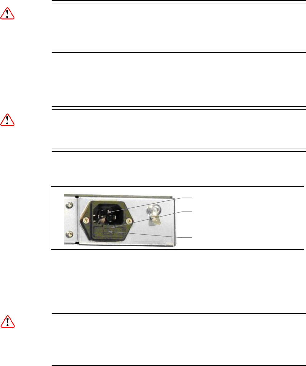
Chapter 7
Warning!
Before replacing the rear panel fuse, disconnect the unit from the supply. Failure to
do this may expose hazardous voltages. Unplug the unit from the local supply
socket.
1. Ensure that power is turned off and the power cable is disconnected from the
AC power inlet.
2. Ease out the fuse carrier by placing a small, flat-bladed screwdriver in the notch
at the top of the carrier.
Caution...
When replacing the power input fuse, always ensure that a fuse of the correct type
and rating is fitted. Failure to do so may result in inadequate protection.
3. Replace the fuse in the carrier.
4. Insert the fuse carrier back in the AC power inlet.
Fuse Carrier
To access the fuse, ease out
the notch with a small flat-
blade screwdriver.
AC Power Inlet
Figure 7.1 Fuse Carrier
If the replacement fuse also blows, do not continue. Disconnect the equipment and
contact Ericsson Customer Services (see Preliminary Pages) for advice.
7.4.5 Power Supply Problems
Warning!
Do not attempt to service the Power Supply Unit as opening or removing covers
may expose dangerous voltages or other hazards. Refer all servicing to service
personnel who have been authorized by Ericsson.
Use the following techniques to fault-find according to the observed symptom(s)
when a power supply failure is suspected.
EN/LZT 790 0005 R1A
7-7

Chapter 7
7.4.6 Summary Status LED Unlit
If the Summary Status LED is unlit, fault-find the problem as detailed in Table 7.2.
Table 7.2 Summary Status LED Unlit Fault-finding
Step Action If Result of Action is Yes… If Result of Action is No…
1 Check Status LED. Is the
unit still working?
If the unit is clearly working
normally then the Status LED
itself is probably at fault. Call a
Service Engineer.
Proceed to next step.
2 Check Power Source.
Connect a known-working
piece of equipment to the
power source outlet. Does it
work?
The problem lies within the unit
or power cable. Proceed to next
step.
The problem lies with the power
source. Check building circuit
breakers, fuse boxes, etc. If
problem persists, contact the
electricity supplier.
3 Check Power Cable and
Fuse. Unplug the power
connector from the unit and
try it in another piece of
equipment. Does it work?
The problem lies within the unit.
Proceed to next step.
The problem lies with either the
cable itself, or with the fuse in
the plug. Replace the fuse or try
to substitute another cable.
4 Check PSU Module(s) and
Fuse(s). Ensure the power
connector is unplugged.
Remove the fuse from the
rear panel connector and
inspect it. Has the fuse
blown?
Replace the fuse with one of
the correct type and rating. If
the PSU still does not work,
unplug the power cable and call
a Service Engineer.
Possible problem with the PSU
module. Call a Service
Engineer.
7.4.7 Fan(s) Not Working/Overheating
The unit is fitted with fans, all of which run continuously. The unit contains a
temperature sensor that will highlight if there is a cooling problem. In the event of
overheating problems, refer to Table 7.3.
Note: Failure to ensure a free air-flow around the unit may cause overheating.
This condition is detected by a temperature sensor; it may be used to trigger
an automatic alarm.
EN/LZT 790 0005 R1A
7-8

Chapter 7
Table 7.3 Fans Not Working/Overheating
Step Action If Result of Action is Yes… If Result of Action is No…
1 Check Fan Rotation. Inspect
the fans located at the sides of
the enclosure. Are the fans
rotating? Check the
temperature (select Chassis /
Temperature Alarms on the
Device Info web page).
Check that the unit has been
installed with sufficient space
allowed for air-flow (see
Chapter 2, Installing the
Equipment). If the ambient air is
too hot, additional cooling may
be required.
Possible break in the DC supply
from the PSU module to the
suspect fan(s). Call a Service
Engineer.
7.4.8 Input Card Failure
Use Table 7.4 to aid in diagnosing a input card fault.
Table 7.4 Input Card Fault-finding
Step Action If Result of Action is Yes… If Result of Action is No…
1 Check the status of the
Input Card. Is there a
modulator failure alarm being
shown on the Status web
page?
If the unit indicates a critical
failure, call a Service Engineer.
If no modulator failure alarm is
shown, go to Step 2.
2 Check the status of the
input ports. Do the ports
reflect the reported status?
Discuss the perceived problem
with Ericsson Customer
Support.
If the port is not providing a valid
input when it has been enabled,
call a Service Engineer.
7.5 Disposal
7.5.1 Moulded Plugs
If the moulded plug fitted to the mains cable supplied with this equipment is not
required, use another cable. If the supplied plug is to be changed, cut it off and
dispose of it safely.
Warning!
If the molded plug fitted to the mains cable supplied with this equipment is not
required, please cut it off and dispose of it safely. Failure to do this may endanger
life as live ends may be exposed if the removed plug is inserted into a mains outlet.
EN/LZT 790 0005 R1A
7-9
Chapter 7
EN/LZT 790 0005 R1A
7-10
7.5.2 Equipment
Dispose of this equipment safely at the end of its life. Local codes and/or
environmental restrictions may affect its disposal. Check with your local authority.

A Glossary
Annex A
The following list covers most of the abbreviations, acronyms and terms as used in
Ericsson Manuals, User and Reference Guides. All terms may not be included in
this Reference Guide.
μm Micrometre (former name - micron): a unit of length equal to one
millionth (10-6) of a metre.
1000BaseT The term for the Electrical Gigabit Ethernet interface. This is the
most common interface for Gigabit Ethernet. Most Gigabit-enabled
PCs and equipment use this interface.
3:2 pull-down A technique used when converting film material (which operates at
24 pictures per second) to 525-line video (operating at 30 pictures
per second).
4:2:0 Digital video coding method in which the colour difference signals
are sampled on alternate lines at half the luminance rate.
4:2:2 Digital video coding method in which the colour difference signals
are sampled on all lines at half the luminance rate.
422P@ML 422 Profile at Main Level: A subset of the MPEG-2 standard, which
supports digital video storage (DVD etc.) and transmissions up to 50
Mbps over various mediums. Used for Contribution and Distribution
applications.
5B6B 5 Binary Bits Encoded to 6 Binary Bits: Block code.
ADPCM Adaptive Differential Pulse Code Modulation: An advanced PCM
technique that converts analogue sound into digital data and vice
versa. Instead of coding an absolute measurement at each sample
point, it codes the difference between samples and can dynamically
switch the coding scale to compensate for variations in amplitude
and frequency.
ACC Authorization Control Computer.
ADT Audio, Data And Teletext.
AFC Automatic Frequency Control.
AFS Automation File Server.
AGC Automatic Gain Control.
EN/LZT 790 0005 R1A
A-1
Annex A
AMOL I and II Automatic Measure of Line-ups I and II: Used by automated
equipment to measure programme-viewing ratings.
ARP Address Resolution Protocol. A protocol used to "resolve" IP
addresses into underlying Ethernet MAC addresses.
ASI Asynchronous Serial Interface.
ASIC Application-Specific Integrated Circuit: A customized chip designed
to perform a specific function.
Async Asynchronous.
ATM Asynchronous Transfer Mode: A connection orientated, cell based,
data transport technology designed for Broadband ISDN (B-ISDN).
It provides a circuit-switched bandwidth-on-demand carrier system,
with the flexibility of packet switching. It offers low end-to-end delays
and (negotiable on call set up) Quality of Service guarantees.
Asynchronous refers to the sporadic nature of the data being
transmitted. Cells are transmitted only when data is to be sent,
therefore the time interval between cells varies according to the
availability of data.
ATSC Advanced Television Standards Committee: An organization
founded in 1983 to research and develop a digital TV standard for
the U.S.A. In late 1996, the FCC adopted the ATSC standard, the
digital counterpart of the NTSC standard.
B3ZS Bipolar with Three Zero Substitution: A method of eliminating long
zero strings in a transmission. It is used to ensure a sufficient
number of transitions to maintain system synchronization when the
user data stream contains an insufficient number of 1s to do so.
B3ZS is the North American equivalent of the European HDB3.
Backward
Compatibility
Refers to hardware or software that is compatible with earlier
versions.
BAT Bouquet Association Table: Part of the service information data. The
BAT provides information about bouquets. It gives the name of the
bouquet and a list of associated services.
baud rate The rate of transfer of digital data when the data comprises
information symbols that may consist of a number of possible states.
Equivalent to bit rate when the symbols only have two states (1 and
0). Measured in Baud.
BER Bit Error Rate: A measure of transmission quality. The rate at which
errors occur in the transmission of data bits over a link. It is
generally shown as a negative exponent, (e.g., 10-7 means that 1 in
10,000,000 bits are in error).
BISS Basic Interoperable Scrambling System: Non-proprietary encryption
from EBU (Tech3290).
Bit rate The rate of transfer of digital data when the data comprises two logic
states, 1 and 0. Measured in bit/s.
Block; Pixel Block An 8-row by 8-column matrix of luminance sample values, or 64
DCT coefficients (source, quantized, or de-quantized).
EN/LZT 790 0005 R1A
A-2
Annex A
Bouquet A collection of services (TV, radio, and data, or any combination of
the three) grouped and sold together, and identified in the SI as a
group. A single service may be in several bouquets.
B-Picture; B-Frame Bi-directionally Predictive Coded Picture/Frame: A picture that is
coded using motion-compensated prediction from previous I or P
frames (forward prediction) and/or future I or P frames (backward
prediction). B frames are not used in any prediction.
BPSK Binary Phase Shift Keying: A data modulation technique.
Buffer A memory store used to provide a consistent rate of data flow.
BW Bandwidth: The transmission capacity of an electronic line such as
(among others) a communications network, computer bus, or
broadcast link. It is expressed in bits per second, bytes per second
or in Hertz (cycles per second). When expressed in Hertz, the
frequency may be a greater number than the actual bits per second,
because the bandwidth is the difference between the lowest and
highest frequencies transmitted. High bandwidth allows fast
transmission or high-volume transmission.
Byte-mode Each byte is delivered separately in the ASI transport stream, with
stuffing data added between the Bytes to increase the data rate to
270 Mbps. See DVB Document A010 rev. 1, Section B3.3, (ASI)
Layer-2 Transport Protocol.
CA Conditional Access: The technology used to control the access to
viewing services to authorized subscribers through the transmission
of encrypted signals and the programmable regulation of their
decryption by a system such as viewing cards.
CAT Conditional Access Table: Part of the MPEG-2 Program Specific
Information (PSI) data. Mandatory for MPEG-2 compliance if CA is
in use.
C-Band The portion of the electromagnetic spectrum, which spans the
frequency range of approximately 4 GHz to 6 GHz. Used by
communications satellites. Preferred in tropical climates because it
is not susceptible to fading.
CCIR See: ITU-R.
CCITT See: ITU-T.
Channel a narrow range of frequencies, part of a frequency band, for the
transmission of radio and television signals without interference from
other channels.
In the case of OFDM, a large number of carriers spaced apart at
precise frequencies are allocated to a channel.
Channel Coding A way of encoding data in a communications channel that adds
patterns of redundancy into the transmission path in order to
improve the error rate. Such methods are widely used in wireless
communications.
EN/LZT 790 0005 R1A
A-3

Annex A
Chrominance The colour part of a TV picture signal, relating to the hue and
saturation but not to the luminance (brightness) of the signal. In a
composite-coded colour system, the colour information
(chrominance, often referred to as chroma) is modulated onto a high
frequency carrier and added to the monochrome-format video signal
carrying the luminance (Y). In a component-coded colour system,
the two colour-difference signals (R-Y)(B-Y) usually referred to as
CRCB (digital) or PRPB (analogue), are used to convey colour
information. When CRCB (PRPB) is added to the luminance (Y), the
complete picture information is conveyed as YCRCB (YPRPB).
Closed Captioning A TV picture subtitling system used with 525-line analogue
transmissions.
CODE Create Once Distribute Everywhere.
Codec The combination of an Encoder and a complementary Decoder
located respectively at the input and output of a transmission path.
COFDM Coded OFDM: COFDM adds forward error correction to the OFDM
transmission consisting of Reed-Solomon (RS) coding followed by
convolutional coding to add extra bits to the transmitted signal. This
allows a large number of errors at the receive end to be corrected by
convolutional (Viterbi) decoding followed by RS decoding.
Composite CVBS Video Signal, 1 V pk-pk
Compression Reduction in the number of bits used to represent the same
information. For the purposes of a broadcast system, it is the
process of reducing digital picture information by discarding
redundant portions of information that are not required when
reconstituting the picture to produce viewing clarity. Compression
allows a higher bite-rate to be transmitted through a given
bandwidth.
Compression
System
Responsible for compressing and multiplexing the video / audio /
data bitstreams, together with the authorization stream. The
multiplexed data stream is then ready for transmission.
CRCB Digital Colour difference signals. These signals, in combination with
the luminance signal (Y), define the colour and brightness of each
picture element (pixel) on a TV line. See: Chrominance
CRC Cyclic Redundancy Check: A mathematical algorithm that computes
a numerical value based on the bits in a block of data. This number
is transmitted with the data and the receiver uses this information
and the same algorithm to ensure the accurate delivery of data by
comparing the results of algorithm and the number received. If a
mismatch occurs, an error in transmission is presumed.
CVBS Colour Video Black Sync Signal
dB Decibels: A ratio of one quantity to another using logarithmic scales
to give results related to human aural or visual perception. dB is a
ratio whereas dBm, for example, is an absolute value, quoted as a
ratio to a fixed point of 0 dBm. 0 dBm is 1 mW at 1 kHz terminated
in 600Ω. 0 dBmV is 1 mV terminated in 75Ω.
EN/LZT 790 0005 R1A
A-4
Annex A
DCE Data Communications Equipment: Typically a modem. It
establishes, maintains and terminates a session on a network but in
itself is not the source (originator) or destination (end receiving unit)
of signals (e.g. a computer, see DTE). A DCE device may also
convert signals to comply with the transmission path (network)
format.
DCT Discrete Cosine Transform: A technique for expressing a waveform
as a weighted sum of cosines. Raw video data is not readily
compressible. DCT is not in itself a compression technique but is
used to process the video data so that it is compressible by an
encoder. DCT processes the picture on an 8x8-pixel block basis,
converting the data from an uncompressible X Y form (as displayed
by an oscilloscope) to a compressible frequency domain form (as
displayed by a spectrum analyzer). Can be forward DCT or inverse
DCT.
DDS Direct Digital Synthesiser.
Decoder The unit containing the electronic circuitry necessary to decode
encrypted signals. Some Decoders are separate from the receiver
but in satellite TV broadcasting, the term is often used
interchangeably as a name for an Integrated Receiver Decoder
(IRD). The term IRD, or IRD / Decoder, is usually associated with
satellite TV broadcasting while Cable systems are based on
Converters or on Set-Top Boxes / Converters.
Decoding Time
stamp
A field that may be present in a PES packet header that indicates
the time that an access unit is to be decoded in the system target
Decoder.
DENG Digital Electronic News Gathering
DID Data Identifier.
Differential Coding Method of coding using the difference between the value of a
sample and a predicted value.
DiffServ Differentiated Services. A mechanism used on layer 3 - e.g. the IP
layer - to differentiate between traffic of various types. DiffServ is
based on the ToS field and provides a mechanism for the network to
give e.g. video traffic higher priority than other traffic (for example
Internet traffic).
DIL Dual In Line: The most common type of package for small and
medium scale integrated circuits. The pins hang vertically from the
two long sides of the rectangular package, spaced at intervals of 0.1
inch.
DIN Deutsches Institut für Normung: German Standards Institute.
Downlink The part of the satellite communications circuit that extends from the
satellite to an Earth station.
Downconvert The process by which the frequency of a broadcast transport stream
is shifted to a lower frequency range.
DPCM Differential Pulse Code Modulation: An audio digitization technique
that codes the difference between samples rather than coding an
absolute measurement at each sample point.
EN/LZT 790 0005 R1A
A-5
Annex A
DSNG Digital Satellite News-Gathering.
DSP Digital Signal Processor.
DTE Data circuit Terminating Equipment: A communications device that
originates (is the source) or is the end receiving unit (destination) of
signals on a network. It is typically a terminal or computer.
DTH Direct-To-Home. The term used to describe uninterrupted
transmission from the satellite directly to the subscriber, that is, no
intermediary cable or terrestrial network utilized.
DTMF Dual-Tone MultiFrequency
DVB Digital Video Broadcasting: A European project which has defined
transmission standards for digital broadcasting systems using
satellite (DVB-S), cable (DVB-C) and terrestrial (DVB-T) medium,
created by the EP-DVB group and approved by the ITU. Specifies
modulation, error correction, etc. (see EN 300 421 for satellite,
EN 300 429 for cable and EN 300 744 for terrestrial).
DVB SI Digital Video Broadcasting Service Information.
DVB-PI DVB-Professional Interfaces: TTV Lan search shows – DVB
Physical Interfaces
DWDM Dense Wavelength Division Multiplexing. A mechanism to utilize
existing fiber with even more bandwidth by adding extra signals
using other wavelengths/colors
Earth Technical Earth: Ensures that all equipment chassis within a rack
are at the same potential, usually by connecting a wire between the
Technical earth terminal and a suitable point on the rack. This is
sometimes known as a Functional earth.
Protective Earth: Used for electric shock protection. This is
sometimes known as a safety earth.
EBU European Broadcast Union.
ECM Entitlement Control Message.
EDI Ethernet Data Input
EIA Electronics Industries Association (USA).
EIT Event Information Table: Equipment: A component of the DVB-
Service Information (SI) stream generated within an Encoder,
containing information about events or programmes such as event
name, start time, duration, etc.
System: EIT (Present/Following) contains the name of the current
and next event. It may include an optional descriptor (synopsis)
giving brief details of content. EIT (Schedule) is used to produce a
full EPG. The EIT is the only DVB-SI table, which can be encrypted.
Elementary Stream A generic term for a coded bitstream, be it video, audio or other.
EMC Electromagnetic Compatibility.
EMM Entitlement Management Message.
EN/LZT 790 0005 R1A
A-6
Annex A
Encryption Encoding of a transmission to prevent access without the
appropriate decryption equipment and authorization.
EPG Electronic Programme Guide: On-screen programme listing using
thumbnail pictures and/or text.
Ethernet The most widely used local area network (LAN) defined by the IEEE
as the 802.3 standard. Transmission speeds vary according to the
configuration. Ethernet uses copper or fibre-optic cables.
ETS European Telecommunications Standard.
ETSI European Telecommunications Standards Institute.
FBAS German for CVBS
FCC Federal Communications Commission.
FDM Frequency Division Multiplex: A common communication channel for
a number of signals, each with its own allotted frequency.
FEC Forward Error Correction: A method of catching errors in a
transmission. The data is processed through an algorithm that adds
extra bits and sends these with the transmitted data. The extra bits
are then used at the receiving end to check the accuracy of the
transmission and correct any errors.
FFT Fast Fourier Transformation: A fast algorithm for performing a
discrete Fourier transform.
FIFO First In, First Out: A data structure or hardware buffer from which
items are taken out in the same order they were put in. Also known
as a shelf from the analogy with pushing items onto one end of a
shelf so that they fall off the other. A FIFO is useful for buffering a
stream of data between a sender and receiver that are not
synchronized - i.e. they not sending and receiving at exactly the
same rate.
FM Frequency Modulation: Analogue modulation procedure
Footprint The area of the Earth’s surface covered by a satellite’s downlink
transmission. Also (generally) the area from which the satellite can
receive uplink transmissions.
FTP File Transfer Protocol: A protocol used to transfer files over a
TCP/IP network (Internet, UNIX, etc.). For example, after developing
the HTML pages for a Web site on a local machine, they are
typically uploaded to the Web server, using FTP. Unlike e-mail
programs in which graphics and program files have to be attached,
FTP is designed to handle binary files directly and does not add the
overhead of encoding and decoding the data.
G.703 The ITU-T standard which defines the physical and electrical
characteristics of hierarchical digital interfaces.
GOP Group of Pictures: MPEG video compression works more effectively
by processing a number of video frames as a block. The Ericsson
AB Encoder normally uses a 12 frame GOP; every twelfth frame is
an I frame.
EN/LZT 790 0005 R1A
A-7
Annex A
GUI Graphical User Interface: The use of pictures rather than just words
to represent the input and output of a program. A program with a
GUI runs under a windowing system and has a screen interface
capable of displaying graphics in the form of icons, drop-down
menus and a movable pointer. The on-screen information is usually
controlled / manipulated by a mouse or keyboard.
HDTV High Definition Television.
HPA High Power Amplifier: Used in the signal path to amplify the
modulated and up-converted broadcast signal for feeding to the
uplink antenna.
HSYNC Horizontal (line) SYNCs.
HTTP HyperText Transfer Protocol. The fundamental protocol used on the
Internet for transmission of WEB pages and other data between
servers and PCs
HU Height Unit
Hub A device in a multi-point network at which branch nodes
interconnect.
ICAM Integrated Conditional Access Module: Embedded in the IRD and
responsible for descrambling, plus packet filtering and reception. It
also contains the physical interface to the subscriber’s viewing card.
ICMP Internet Control Message Protocol. ICMP messages, delivered in IP
packets, are used for out-of-band messages related to network
operation or mis-operation
IGMP Internet Group Management Protocol. IGMP is a protocol used to
manage multicasts on the Internet. For a host (receiver unit) to
receive a multicast, it needs to transmit IGMP "join" messages on
the right format. Three versions exist. IGMPv2 is common today but
IGMPv3 is the next step.
IDU Indoor unit
IEC International Electrotechnical Committee.
IF Intermediate Frequency: Usually refers to the 70 MHz or 140 MHz
output of the Modulator in cable, satellite and terrestrial transmission
applications.
Interframe Coding Compression coding involving consecutive frames. When
consecutive frames are compared, temporal redundancy is used to
remove common elements (information) and arrive at difference
information. MPEG-2 uses B and P frames, but since they are
individually incomplete and relate to other adjacent frames, they
cannot be edited independently.
Intraframe Coding Compression coding involving a single frame. Redundant
information is removed on a per frame basis. All other frames are
ignored. Coding of a macroblock or picture that uses information
only from that macroblock or picture. Exploits spatial redundancy by
using DCT to produce I frames; these are independent frames and
can be edited.
EN/LZT 790 0005 R1A
A-8
Annex A
IP Internet Protocol: The IP part of TCP/IP. IP implements the network
layer (layer 3) of the protocol, which contains a network address and
is used to route a message to a different network or sub-network. IP
accepts packets from the layer 4 transport protocol (TCP or UDP),
adds its own header to it and delivers a datagram to the layer 2 data
link protocol. It may also break the packet into fragments to support
the Maximum Transmission / Transfer Unit (MTU) of the network.
I-picture; I-frame Intracoded Picture/Frame: A picture / frame, which is coded using
purely intracoding with reference to no other field or frame
information. The I frame is used as a reference for other
compression methods.
IPPV Impulse Pay Per View: One-time events, purchased at home (on
impulse) using a prearranged SMS credit line.
IRD Integrated Receiver Decoder: The Receiver with an internal MPEG
Decoder, which is connected to the subscriber’s TV. The IRD is
responsible for receiving and de-multiplexing all signals. The unit
receives the incoming signal and if CA is active, decodes the signal
when provided with a control word by the viewing card. Domestic
IRDs are also known as Set-Top Units or Set-Top Boxes.
IRE Institute of Radio Engineers: No longer in existence but the name
lives on as a unit of video amplitude measurement. This unit is 1%
of the range between blanking a peak white for a standard
amplitude signal.
ISDN Integrated Services Digital Network: The basic ISDN service is BRI
(Basic Rate Interface), which is made up of two 64 kbps B channels
and one 16 kbps D channel (2B+D). If both channels are combined
into one, called bonding, the total data rate becomes 128 kbps and
is four and a half times the bandwidth of a V.34 modem (28.8 kbps).
The ISDN high speed service is PRI (Primary Rate Interface). It
provides 23 B channels and one 64 kbps D channel (23B+D), which
is equivalent to the 24 channels of a T1 line. When several channels
are bonded together, high data rates can be achieved. For example,
it is common to bond six channels for quality videoconferencing at
384 kbps. In Europe, PRI includes 30 B channels and one D
channel, equivalent to an E1 line.
ISO International Standards Organisation.
ISOG Inter-union Satellite Operations Group.
ITS Insertion Test Signal: A suite of analogue test signals placed on
lines in the VBI. Also known as VITS.
ITT Invitation To Tender.
ITU-R International Telecommunications Union - Radiocommunications
Study Groups (was CCIR).
ITU-T International Telecommunications Union - Telecommunications
Standardization Sector (was CCITT).
EN/LZT 790 0005 R1A
A-9
Annex A
JPEG Joint Photographic Experts Group: ISO/ITU standard for
compressing still images. It has a high compression capability.
Using discrete cosine transform, it provides user specified
compression ratios up to around 100:1 (there is a trade-off between
image quality and file size).
kbps 1000 bits per second.
Kbit 1024 bits, usually refers to memory capacity or allocation.
Ku-band The portion of the electromagnetic spectrum, which spans the
frequency range of approximately 12 GHz to 14 GHz. Used by
communications satellites. Preferred for DTH applications because
this range of frequency is less susceptible to interference.
LAN Local Area Network: A network, which provides facilities for
communications within a defined building or group of buildings in
close proximity.
L-band The frequency band from 950 MHz to 2150 MHz, which is the
normal input-frequency-range of a domestic IRD. The incoming
signal from the satellite is down-converted to L-band by the LNB.
LED Light Emitting Diode.
LNB Low Noise Block Down-Converter: The component of a subscriber
satellite transmission receiving dish which amplifies the incoming
signal and down-converts it to a suitable frequency to input to the
IRD (typically 950 MHz - 1600 MHz).
LO Local Oscillator.
lsb Least significant bit.
Luminance The television signal representing brightness, or the amount of light
at any point in a picture. The Y in YCRCB.
LVDS Low Voltage Differential Signal: LVDS is a generic multi-purpose
Interface standard for high speed / low power data transmission. It
was standardized in ANSI/TIA/EIA-644-1995 Standard (aka RS-
644).
Macroblock A 16x16-pixel area of the TV picture. Most processing within the
MPEG domain takes place with macro blocks. These are converted
to four 8x8 blocks using either frame DCT or field DCT. Four 8 x 8
blocks of luminance data and two (4:2:0 chrominance format), four
(4:2:2) or eight (4:4:4) corresponding 8 x 8 blocks of chrominance
data coming from a 16 x 16 section of the luminance component of
the picture. Macroblock can be used to refer to the sample data and
to the coded representation of the sample values and other data
elements.
Mbps Million bits per second.
MCC Multiplex Control Computer: A component of a System 3000
compression system. The MCC sets up the configuration for the
System 3000 Multiplexers under its control. The MCC controls both
the main and backup Multiplexer for each transport stream.
MCPC Multiple Channels Per Carrier.
EN/LZT 790 0005 R1A
A-10
Annex A
MEM Multiplex Element Manager: A GUI-based control system, part of the
range of Ericsson AB compression system control element products.
The evolution 5000 MEM holds a model of the system hardware.
Using this model, it controls the individual system elements to
configure the output multiplexes from the incoming elementary
streams. The MEM monitors the equipment status and controls any
redundancy switching.
Meta-data Meta-data is descriptive data that is "tagged" to a movie or audio
clip. Meta-data is essential for the broadcaster.
MMDS Multichannel Microwave Distribution System: A terrestrial microwave
direct-to-home broadcast transmission system.
Motion
Compensation
The use of motion vectors to improve the efficiency of the prediction
of sample values. The prediction uses motion vectors to provide
offsets into the past and/or future reference frames or fields
containing previously decoded sample values that are used to form
the prediction error signal.
Motion Estimation The process of estimating motion vectors in the encoding process.
Motion Vector A two-dimensional vector used for motion compensation that
provides an offset from the coordinate position in the current picture
or field to the coordinates in a reference frame or field.
MP@ML Main Profile at Main Level: A subset of the MPEG-2 standard, which
supports digital video storage (DVD etc.) and transmissions up to 15
Mbps over various mediums.
MP@HL Main Profile at High Level: A subset of the MPEG-2 standard, which
supports digital video storage (DVD etc.) and transmissions up to 80
Mbps over various mediums.
MPEG Moving Pictures Experts Group: The name of the ISO/IEC working
group which sets up the international standards for digital television
source coding.
MPEG-2 Industry standard for video and audio source coding using
compression and multiplexing techniques to minimise video signal
bit rate in preparation for broadcasting. Specified in ISO/IEC 13818.
The standard is split into layers and profiles defining bit rates and
picture resolutions.
MPLS Multi-protocol Label Switching. A Quality of Service mechanism for
IP networks that allow IP packets to flow along a predefined path in
a network, improving the reliability and robustness of the
transmission.
MPTS Multi-Program Transport Streams. Transport Streams that carry
multiple TV/Radio services.
msb Most significant bit.
Msymbol/s (Msym/s) Mega (million) Symbols per second (106 Symbols per
second).
Multiplex A number of discrete data streams (typically 8 to 12), from
encoders, that are compressed together in a single DVB compliant
transport stream for delivery to a Modulator.
EN/LZT 790 0005 R1A
A-11
Annex A
Multicast An IP mechanism that allows transmission of data to multiple
receivers. A multicast can also have several transmit sources
simultaneously. In video applications, multicast is typically used to
distribute a video signal from a central source to multiple
destinations.
MUSICAM Masking pattern adapted Universal Sub-band Integrated Coding
And Multiplexing: An audio bit rate reduction system relying on sub-
band coding and psychoacoustic masking.
Mux Multiplexer: Transmission Multiplexer: receives EMMs from the
ACC, ECMs from the BCC, video/audio data from the encoders, and
the SI stream from the SIC. It then multiplexes them all into a single
DVB-compliant transport stream, and delivers the signal to the
uplink after modulation.
The Multiplexer also contains the cypher card, which scrambles the
services according to the control words supplied by the BCC.
Network In the context of broadcasting: a collection of MPEG-2 transport
stream multiplexes transmitted on a single delivery system, for
example, all digital channels on a specific cable system.
NICAM Near Instantaneously Companded Audio Multiplex: Official name is
NICAM 728. Used for digital stereo sound broadcasting in the UK
employing compression techniques to deliver very near CD quality
audio. 728 refers to the bit rate in kbps.
NIT Network Information Table: Part of the service information data. The
NIT provides information about the physical organization of each
transport stream multiplex, and the characteristics of the network
itself (such as the actual frequencies and modulation being used).
nm Nanometre: a unit of length equal to one thousand millionth (10-9) of
a metre.
NMS Network Management System. A system used to supervise
elements in an IP network. When a device reports an alarm, the
alarm will be collected by the NMS and reported to the operator.
NMS systems typically collect valuable statistics information about
the network performance and can warn the operator early.
NTSC National Television Systems Committee: The group, which
developed analogue standards used in television broadcast systems
in the United States. Also adopted in other countries (e.g. Mexico,
Canada, Japan). This system uses 525 picture lines and a 59.97 Hz
field frequency.
NVOD Near Video On-Demand: Method of offering multiple showings of
movies or events. The showings are timed to start at set intervals,
determined by the broadcaster. Each showing of a movie or event
can be sold to subscribers separately.
NVRAM Non-volatile Random Access Memory: Memory devices (permitting
random read / write access) that do not lose their information when
power is removed. Stores the default configuration parameters set
by the user.
ODU Outdoor Unit
EN/LZT 790 0005 R1A
A-12
Annex A
OFDM Orthogonal Frequency Division Multiplex: A modulation technique
used for digital TV transmission in Europe, Japan and Australia;
more spectrally efficient than FDM. In OFDM, data is distributed
over a large number of carriers spaced apart at precise frequencies.
The carriers are arranged with overlapping sidebands in such a way
that the signals can be received without adjacent channel
interference.
OPPV Order ahead Pay Per View: An advance purchase of encrypted one-
time events with an expiry date.
OSD On-screen display: Messages and graphics, typically originating
from the SMS, and displayed on the subscriber’s TV screen by the
IRD, to inform the subscriber of problems or instruct the subscriber
to contact the SMS.
Packet A unit of data transmitted over a packet switching network. A packet
consists of a header followed by a number of contiguous bytes from
an elementary data stream.
PAL Phase Alternating Line: A colour TV broadcasting system where the
phase of the R-Y colour-difference signal is inverted on every
alternate line to average out errors providing consistent colour
reproduction.
PAT Program Association Table: Part of the MPEG-2 Program Specific
Information (PSI) data and is mandatory for MPEG-2 compliance.
The PAT points (maps) to the PMT.
PCM Pulse Code Modulation: A process in which a signal is sampled,
each sample is quantized independently of other samples, and the
resulting succession of quantized values is encoded into a digital
signal.
PCR Program Clock Reference: A time stamp in the transport stream
from which the Decoder timing is derived.
PDC Program Delivery Control: A Teletext service allowing simple
programming (i.e. VideoPlus) of VCR recording times. If the desired
program is rescheduled, PDC updates the programming information
in the VCR.
Pel Picture Element: Also known as a pixel. The smallest resolvable
rectangular area of an image either on a screen or stored in
memory. On-screen, pixels are made up of one or more dots of
colour. Monochrome and grey-scale systems use one dot per pixel.
For grey-scale, the pixel is energized with different intensities,
creating a range from dark to light (a scale of 0-255 for an eight-bit
pixel). Colour systems use a red, green and blue dot per pixel, each
of which is energized to different intensities, creating a range of
colours perceived as the mixture of these dots. If all three dots are
dark, the result is black. If all three dots are bright, the result is
white.
EN/LZT 790 0005 R1A
A-13
Annex A
PES Packetised Elementary Stream: A sequential stream of data bytes
that has been converted from original elementary streams of audio
and video access units and transported as packets. Each PES
packet consists of a header and a payload of variable length and
subject to a maximum of 64 kbytes. A time stamp is provided by the
MPEG-2 systems layer to ensure correct synchronization between
related elementary streams at the Decoder.
PID Packet Identifier: the header on a packet in an elementary data
stream, which identifies that data stream. An MPEG-2 / DVB
standard.
PIN Personal Identification Number: A password used to control access
to programming and to set purchase limits. Each subscriber
household can activate several PINs and may use them to set
individual parental rating or spending limits for each family member.
Pixel PIX (picture) Element: The digital representation of the smallest
area of a television picture capable of being delineated by the
bit-stream. See Pel for more information.
pk-pk peak to peak: Measurement of a signal or waveform from its most
negative point to its most positive point.
PLL Phase-Locked Loop. A phase-locked loop is a control system which
controls the rotation of an object by comparing its rotational position
(phase) with another rotating object as in the case of a sine wave or
other repeating signal. This type of control system can synchronize
not only the speed, but also the angular position of two waveforms
that are not derived from the same source.
PMT Program Map Table: Part of the MPEG-2 Program Specific
Information (PSI) data and is mandatory for MPEG-2 compliance.
Each service has a PMT, which lists the component parts
(elementary streams of video, audio, etc.) for the various services
being transmitted.
P-picture/P-frame A picture / frame produced using forward prediction. It contains
predictions from either previous I frames or previous P frames. The
P frame is used as a reference for future P or B frames.
ppm Parts per million.
PPV Pay Per View: A system of payment for viewing services based on a
usage / event basis rather than on on-going subscription.
Subscribers must purchase viewing rights for each PPV event that
they wish to view. PPV events may be purchased as IPPV or OPPV.
Program PC - A sequence of instructions for a computer.
TV - A concept having a precise definition within ISO 13818-1
(MPEG-2). For a transport stream, the timebase is defined by the
PCR. The use of the PCR for timing information creates a virtual
channel within the stream.
Programme A linking of one or more events under the control of a broadcaster.
For example, football match, news, film show. In the MPEG-2
concept, the collection of elementary streams comprising the
programme, have a common start and end time. A series of
programmes are referred to as events.
EN/LZT 790 0005 R1A
A-14
Annex A
PRPB Analogue Colour difference signals. Refer to CRCB for an
explanation.
PROM Programmable Read-Only Memory: A device, which may be written
once with data for permanent storage, and then read whenever
required. Special types of PROM permit the erasure of all data by
Ultraviolet light (EPROM) or by application of an electronic signal
(EEPROM).
PS Program Stream: A combination of one or more PESs with a
common timebase.
PSI Program Specific Information: Consists of normative data, which is
necessary for the de-multiplexing of transport streams and the
successful regeneration of programs (see also: SI).
PSIP Program System Information Protocol: The ATSC equivalent of SI
for DVB.
PSK Phase Shift Keying: A method of modulating digital signals
particularly suited to satellite transmission.
PSR Professional Satellite Receiver: See also: IRD.
PSU Power Supply Unit.
QAM Quadrature Amplitude Modulation: A method of modulating digital
signals, which uses combined techniques of phase modulation and
amplitude modulation. It is particularly suited to cable networks.
QoS Quality of Service. A common term for a set of parameters
describing the quality you get from an IP network: Throughput,
availability, delay, jitter and packet loss.
QPSK Quadrature Phase Shift Keying: A form of phase shift keying
modulation using four states.
QSIF Quarter Screen Image Format.
Quantise A process of converting analogue waveforms to digital information.
8-bit quantization as set out in ITU-R Rec. 601. Uses 256 levels in
the range 0 – 255 to determine the analogue waveform value at any
given point. The value is then converted to a digital number for
processing in the digital domain.
RAM Random Access Memory: A volatile storage device for digital data.
Data may be written to, or read from, the device as often as
required. When power is removed, the data it contains is lost.
RAS Remote Authorization System: A Ericsson AB proprietary public-key
encryption system used to prevent unauthorized viewing of a TV
programme or programmes.
RF Radio Frequency.
RGB Red, Green, Blue: The Chroma information in a video signal.
RIP2 Routing Information Protocol v2. A protocol used between network
routers to exchange routing tables and information.
EN/LZT 790 0005 R1A
A-15
Annex A
ROM Read Only Memory: A non-volatile storage device for digital data.
Data has been stored permanently in this device. No further
information may be stored (written) there and the data it holds
cannot be erased. Data may be read as often as required.
RS Reed-Solomon coding: An error detection and correction, coding
system. 16 bytes of Reed-Solomon Forward Error Correction code
are appended to the packet before transmission bringing the packet
length to 204 bytes. The 16 bytes are used at the receiving end to
correct any errors. Up to eight corrupted bytes can be corrected.
RSVP ReSerVation Protocol. A Quality-of-service oriented protocol used
by network elements to reserve capacity in an IP network before a
transmission takes place.
RTP Real-time Transfer Protocol. A protocol designed for transmission of
real-time data like video and audio over IP networks. RTP is used
for most video over IP transmissions.
RLC Run Length Coding: Minimization of the length of a bit-stream by
replacing repeated characters with an instruction of the form ‘repeat
character x y times’.
SCPC Single Channel Per Carrier.
Spectral
Scrambling
A process (in digital transmission) used to combine a digital signal
with a pseudo-random sequence, producing a randomized digital
signal that conveys the original information in a form optimized for a
broadcast channel.
Scrambling Alteration of the characteristics of a television signal in order to
prevent unauthorized reception of the information in clear form.
SDI Serial Digital Interface.
SDT Service Description Table: Provides information in the SI stream
about the services in the system; for example, the name of the
service, the service provider, etc.
SDTI Serial Data Transport Interface. A mechanism that allows
transmission of various types of data over an SDI signal. This may
be one or more compressed video signals or other proprietary data
types. The advantage of SDTI is that existing SDI transmission
infrastructure can be used to transport other types of data.
SELV Safety Extra Low Voltage (EN 60950).
SFP Small Form-factor Pluggable module. A standardized mechanism to
allow usage of various optical interfaces for Gigabit Ethernet.
Several types of SFP modules exist: Single-mode fiber modules for
long-distance transmission and multi-mode fiber modules for shorter
distances. SFP is also known as "mini-GBIC".
SIP Session Initiation Protocol. A common acronym for the ongoing
effort to standardize signaling over IP networks, i.e. connection
set-up and tear-down. SIP makes it possible to "dial" a remote
receiver of data and set-up the connection in this way.
EN/LZT 790 0005 R1A
A-16
Annex A
STB Set-Top Box: A box that sits on top of a television set and is the
interface between the home television and the cable TV company.
New technologies evolving for set-top boxes are video-on-demand,
video games, educational services, database searches, and home
shopping. The cable equivalent of the IRD.
SFN Single Frequency Network: The SFN technique allows large
geographic areas to be served with a common transmission
multiplex. All transmitters in the network are synchronously
modulated with the same signal and they all radiate on the same
frequency. Due to the multi-path capability of the multi-carrier
transmission system (COFDM), signals from several transmitters
arriving at a receiving antenna may contribute constructively to the
total wanted signal. The SFN technique is not only frequency
efficient but also power efficient because fades in the field strength
of one transmitter may be filled by another transmitter.
SI Service Information: Digital information describing the delivery
system, content and scheduling (timing) of broadcast data streams.
DVB-SI data provides information to enable the IRD to automatically
demultiplex and decode the various streams of programmes within
the multiplex. Specified in ISO/IEC 13818[1]. (DVB)
Single Packet Burst
Mode
A burst of ASI bytes (either 188 or 204, depending on packet length)
is contiguously grouped into an MPEG-2 transport stream packet.
Stuffing data is added between the packets to increase the data rate
to 270 Mbps. See DVB Document A010 rev. 1, Section B3.3, (ASI)
Layer-2 Transport Protocol.
Smart Card A plastic card with a built-in microprocessor and memory used for
identification, financial transactions or other authorizing data
transfer. When inserted into a reader, data is transferred to and from
the host machine or a central computer. It is more secure than a
magnetic stripe card and it can be disabled if the wrong password is
entered too many times. As a financial transaction card, it can be
loaded with digital money and used in the same way as cash until
the balance reaches zero. The file protocol is specific to its intended
application.
SMATV Satellite Mast Antenna Television: A distribution system, which
provides sound and television signals to the households of a
building or group of buildings, typically used to refer to an apartment
block.
SMPTE Society of Motion Picture and Television Engineers.
SMS Subscriber Management System: A system which handles the
maintenance, billing, control and general supervision of subscribers
to conditional access technology viewing services provided through
cable and satellite broadcasting. An SMS can be an automatic (e.g.
Syntellect) system where subscribers order entitlements by entering
information via a telephone. Alternatively, an SMS can be a manual
system, which requires subscribers to speak with an operator who
then manually enters their entitlement requests. Some systems
support multiple SMSs.
SNG Satellite News-Gathering.
SNMP Simple Network Management Protocol.
EN/LZT 790 0005 R1A
A-17
Annex A
SNTP Simple Network Time Protocol is an Internet protocol used to
synchronize the clocks of computers to some time reference. It is a
simplified version of the protocol NTP protocol which is too
complicated for many systems.
Spatial Redundancy Information repetition due to areas of similar luminance and/or
chrominance characteristics within a single frame. Removed using
DCT and Quantization (Intra-Frame Coding).
SPI Synchronous Parallel Interface.
Statistical
Redundancy
Data tables are used to assign fewer bits to the most commonly
occurring events, thereby reducing the overall bit rate. Removed
using Run Length Coding and Variable Length Coding.
TAXI Transparent Asynchronous Tx / Rx Interface: A proprietary high
speed data interface.
TCP / IP Transmission Control Protocol/Internet Protocol: A set of
communications protocols that may be used to connect different
types of computers over networks.
TDM Time Division Multiplex: One common, communications channel
carrying a number of signals, each with its own allotted time slot.
TDT Time and Date Table: Part of the DVB Service Information. The TDT
gives information relating to the present time and date.
Temporal
Redundancy
Information repetition due to areas of little or no movement between
successive frames. Removed using motion estimation and
compensation (Inter-Frame Coding).
Time stamp A term that indicates the time of a specific action such as the arrival
of a byte or the presentation of a presentation unit.
TOT Time Offset Table: This optional SI table supports the use of local
offsets as well as the UTC time/date combination. The purpose of
the table is to list by country the current offset from UTC and the
next expected change to that offset (to track when daylight saving
occurs). The offset resolution is to within 1 minute over a range of
±12 hours from UTC.
Transport Stream A set of packetised elementary data streams and SI streams, which
may comprise more than one programme, but with common
synchronization and error protection. The data structure is defined in
ISO/IEC 13818-1 [1] and is the basis of the ETSI Digital Video
Broadcasting standards.
Transport Stream
Packet Header
A data structure used to convey information about the transport
stream payload.
TS Transport Stream.
TSDT Transport Stream Descriptor Table: A component of the MPEG-2
PSI data. This table describes which type of Transport stream it is in
(i.e. DVB, ATSC etc.). It may also contain other descriptors.
TSP Transport Stream Processor.
U 44.45 mm (rack height standard).
EN/LZT 790 0005 R1A
A-18
Annex A
UART Universal Asynchronous Receiver Transmitter: A device providing a
serial interface for transmitting and receiving data.
UDP User Datagram Protocol. A protocol above the IP layer that provides
port multiplexing in addition. In essence, you can transmit IP data
packets to several receiving processes in the same unit/device.
Unicast Point-to-point connection, i.e. the "opposite" of multicast which is
one to many (or many to many). In this mode, a transmit unit sends
video data direct to a unique destination address.
Upconvert The process by which the frequency of a broadcast transport stream
is shifted to a higher frequency range.
Uplink The part of the communications satellite circuit that extends from the
Earth to the satellite.
UPS Uninterruptable Power Supply: A method of supplying backup power
when the electrical power fails or drops to an unacceptable voltage
level. Small UPS systems provide battery power for a few minutes;
enough to power down the computer in an orderly manner. This is
particularly important where write back cache is used. Write back
cache is where modified data intended for the disk is temporarily
stored in RAM and can be lost in the event of a power failure.
Sophisticated systems are tied to electrical generators that can
provide power for days. UPS systems typically provide surge
suppression and may provide voltage regulation.
UTC Universal Time Coordinate: An internationally agreed basis for
timekeeping introduced in 1972 and based on international atomic
time (corresponds to Greenwich Mean Time or GMT).
VITC Vertical Interval Time Code.
VITS Vertical Interval Test Signal: See: ITS.
VLAN Virtual LAN, a network of units that behave as if they are connected
to the same wire even though they may actually be physically
located on different segments of a LAN.
VPS Video Programming System: A German precursor to PDC
WSS Wide Screen Switching: Data used in wide-screen analogue
services, which enables a receiver to select the appropriate picture
display mode.
WST World System Teletext: System B Teletext. Used in 625 line / 50 Hz
television systems
(ITU-R 653).
XILINX A type of programmable Integrated Circuit.
XLR Audio connector featuring three leads, two for signal and one for
GND.
XML eXtensible Markup Language. A very common self-describing text-
based data format. Used for many purposes: Meta-data,
configuration files, documents, etc. The readability of the format has
made it very popular and is now the fundament for many types of
WEB services.
EN/LZT 790 0005 R1A
A-19
Annex A
EN/LZT 790 0005 R1A
A-20
Y (Luminance) Defines the brightness of a particular point on a TV line. The only
signal required for black and white pictures.
Y/C Broadcast video with separate colour, Y (luminance) and C
(Chroma) (sometimes called S-Video).
YUV Y: Luminance component (Brightness), U and V: Chrominance
(Colour difference)

B Technical Specification
Annex B
Contents
B.1 Output...................................................................................................B-3
B.1.1 Supported Video Resolutions ...............................................................B-3
B.1.2 Supported Video Bit Rates ...................................................................B-3
B.1.3 Composite Video Output ......................................................................B-4
B.1.4 Analogue HD Video Output ..................................................................B-5
B.1.5 HD SDI Digital Video ............................................................................B-7
B.2 Audio Decoding and Output Stage .......................................................B-7
B.2.1 General.................................................................................................B-7
B.2.2 MPEG Audio.........................................................................................B-8
B.2.3 Dolby Digital AC-3 Audio ......................................................................B-8
B.3 Audio Output Format ............................................................................B-8
B.3.1 General.................................................................................................B-8
B.3.2 Analogue Audio ....................................................................................B-8
B.3.3 Audio Routing .....................................................................................B-10
B.3.4 Lip Sync..............................................................................................B-10
B.3.5 Supported Audio Specifications..........................................................B-10
B.3.6 Supported Audio Bit Rates .................................................................B-10
B.3.7 Digital Audio Outputs..........................................................................B-11
B.4 Input Specifications ............................................................................B-11
B.4.1 DVB-S2 Satellite Receivers................................................................B-11
B.4.1.1 General...............................................................................................B-11
B.4.1.2 LNB Power and Control......................................................................B-14
B.4.2 8-VSB Terrestrial Receivers ...............................................................B-15
B.4.2.1 General...............................................................................................B-15
B.4.3 DVB-ASI Input ....................................................................................B-16
B.4.4 100/1000BaseT Dual NIC Input Receivers.........................................B-16
B.4.5 Frame Sync Connector.......................................................................B-16
B.5 Output Specifications..........................................................................B-17
B.5.1 Video Outputs.....................................................................................B-17
B.5.2 Audio Outputs.....................................................................................B-17
B.5.3 Alarm Connector.................................................................................B-17
B.5.4 DVB-ASI Output .................................................................................B-18
B.5.5 1000BaseT IP Output .........................................................................B-18
B.6 Environmental.....................................................................................B-19
B.6.1 Conditions...........................................................................................B-19
B.6.2 Physical ..............................................................................................B-19
B.7 Power Supply – AC Mains Input.........................................................B-20
EN/LZT 790 0005 R1A
B-1
Annex B
EN/LZT 790 0005 R1A
B-2
B.8 Cable Types .......................................................................................B-20
B.9 Compliance ........................................................................................B-21
B.9.1 Safety .................................................................................................B-21
B.9.2 EMC ...................................................................................................B-22
B.9.3 Telecommunications ..........................................................................B-22
B.9.4 CE Marking ........................................................................................B-22
B.9.5 C-Tick Mark........................................................................................B-23
B.9.6 Packaging Statement .........................................................................B-23
B.9.7 Packaging Markings...........................................................................B-23
B.9.8 Materials Declarations........................................................................B-24
B.9.8.1 For the European Union..................................................................... B-24
B.9.8.2 For China ...........................................................................................B-24
B.9.9 Equipment Disposal ...........................................................................B-25
B.9.9.1 General ..............................................................................................B-25
B.9.9.2 For the European Union..................................................................... B-25
B.9.10 Recycling............................................................................................ B-25
List of Tables
Table B.1 Supported Video Resolutions...............................................................B-3
Table B.2 Supported Video Rates ........................................................................B-3
Table B.3 625 Line ...............................................................................................B-4
Table B.4 525 Line ...............................................................................................B-4
Table B.5 HD Analogue Output Specification.......................................................B-5
Table B.6 Sync Output Specification ....................................................................B-6
Table B.7 Digital Video Output Connectors..........................................................B-7
Table B.8 Analogue Audio Performance Specifications ......................................B-9
Table B.9 Supported Audio Specifications .........................................................B-10
Table B.10 Supported Audio Data Bit Rates (MPEG-2) ....................................... B-10
Table B.11 DVB-S2 Satellite Receiver Input Specification................................... B-11
Table B.12 DVB-S2 Satellite Input – DVB-S Eb/No Ratio .................................... B-13
Table B.13 DVB-S2 Satellite Input – DVB-S2 Es/No Ratio .................................. B-14
Table B.14 LNB Power and Control......................................................................B-15
Table B.15 8-VSB Receiver Input Specification ...................................................B-15
Table B.16: DVB-ASI Copper ...............................................................................B-16
Table B.17 100/1000BaseT IP Dual NIC Input Specifications.............................. B-16
Table B.18 Frame Sync Connector ......................................................................B-17
Table B.19 Relay Alarm Output Specification.......................................................B-17
Table B.20: DVB-ASI Copper ...............................................................................B-18
Table B.21 1000BaseT IP Output Specifications..................................................B-18
Table B.22 Environmental Conditions .................................................................B-19
Table B.23 Physical Parameters (RX83XX) ........................................................ B-19
Table B.24 Physical Parameters (RX8200)..........................................................B-19
Table B.25 AC Power Supply Specification.........................................................B-20
Table B.26 Suitable Signal Cable Types ..............................................................B-21

Annex B
B.1 Output
B.1.1 Supported Video Resolutions
The RX8000 Receiver supports MPEG-2 and MPEG-4 AVC, 4:2:0.
Table B.1 Supported Video Resolutions
Input Resolutions
(H x V)
Frame-Rates Output Format
(H x V)
Specification
1920 x 1080
1440 x 1080
1280 x 1080
960 x 1080
29.97
25
720 x 480 interlaced,
1920 x 1080 interlaced
720 x 576 interlaced,
1920 x 1080 interlaced
SMPTE 274M
1280 x 720
960 x 720
59.94
50
720 x 480 interlaced,
1280 x 720 progressive
720 x 576 interlaced,
1280 x 720 progressive
SMPTE 296M
All SD Formats 29.97
25
720 x 480 interlaced
720 x 576 interlaced
SMPTE 174M
B.1.2 Supported Video Bit Rates
The equipment supports decoding of non-encrypted compressed video at rates of
up to 80 Mbps MPEG-2 and 85 Mbps MPEG-4 AVC.
Table B.2 Supported Video Rates
Coding
Technology
Parameter Limit
MPEG-4 AVC Level 3 12 Mbps
MPEG-4 AVC Level 4 25 Mbps
MPEG-4 AVC Level 4.2 50 Mbps CABAC, 85 Mbps CAVLC
MPEG-2 4:2:0, Main Level 15 Mbps
MPEG-2 4:2:0, High Level 80 Mbps
MPEG-2 4:2:2, Main Level 50 Mbps
MPEG-2 4:2:2, High Level 90 Mbps
EN/LZT 790 0005 R1A
B-3

Annex B
B.1.3 Composite Video Output
The equipment supports video decoding as per ITU-R BT.470 and ANSI/SMPTE
170M.
Table B.3 625 Line
Description Test Signal Limit
Bar Level VITS17 700mV +/- 7mV
Bar Tilt VITS17 <0.5%
Sync Level VITS17 300mV +/- 3mV
DC Offset VITS17 +/- 100mV
Chrominance to Luminance
Gain Inequality
Colour Bars 100 +/- 5%
Chrominance to Luminance
Phase Inequality
VITS17 <20nS
K factor K 2T VITS17 <1%
Pulse X bar K rating VITS17 100 +/- 1%
Frequency Response
(MultiBurst)
VITS18 0. 5 MHz
VITS18 1 MHz
VITS18 2 MHz
VITS18 4 MHz
VITS18 4.8 MHz
VITS18 5.8 MHz
0dB +/- 0.2 dB
0dB +/- 0.2 dB
0dB +/- 0.2 dB
0dB +/- 0.3 dB
0dB +/- 0.3 dB
0dB +/- 0.8 dB
Differential Gain VITS330 <1.5%
Differential Phase VITS330 <1 Degree
Non-Linearity VITS17 <5%
Jitter VITS17 <5nS
Weighted Luminance Noise Luminance Ramp <60 dB
Weighted Luminance Noise Flat Grey Field <63 dB
Chrominance PM Noise Flat Red Field <55 dB
Table B.4 525 Line
Description Test Signal Limit
Bar Level NTC-7 comp 100 IRE +/- 1 IRE
Bar Tilt NTC-7 comp <0.5%
Sync Level NTC-7 comp 40 IRE +/- 0.5 IRE
EN/LZT 790 0005 R1A
B-4

Annex B
Description Test Signal Limit
DC Offset NTC-7 comp +/- 100mV
Chrominance to Luminance
Gain Inequality
NTC-7 comp 100 +/- 5%
Chrominance to Luminance
Phase Inequality
NTC-7 comp <20nS
K factor K 2T NTC-7 comp <1%
Pulse X bar K rating 100 +/- 1%
Frequency Response
(MultiBurst)
FCC Multi-
burst
0.5 MHz
1.25 MHz
2 MHz
3 MHz
3.58 MHz
4.1 MHz
0dB +/- 0.2 dB
0dB +/- 0.2 dB
0dB +/- 0.2 dB
0dB +/- 0.2 dB
0dB +/- 0.3 dB
0dB +/- 0.3 dB
Differential Gain NTC-7 comp <2%
Differential Phase NTC-7 comp <1 Degree
Non-Linearity NTC-7 comp <5%
Jitter <5nS
Weighted Luminance Noise Luminance
Ramp
<60 dB
Weighted Luminance Noise Flat Grey
Field
<63 dB
Chrominance PM Noise Flat Red
Field
<55 dB
B.1.4 Analogue HD Video Output
Table B.5 HD Analogue Output Specification
Parameter Value for
Y, R, G, B
Value for
Pb, Pr
Condition Notes
Amplitude 700 mV ± 2% 700 mV ± 2% 100% colour
bar
DC offset ± 10 mV ± 10 mV Black field
Bandwidth DC to 10 MHz ±
0.2 dB
10 MHz to 20 MHz
DC to 10 MHz ±
0.2 dB
10 MHz to 15
Sweep
EN/LZT 790 0005 R1A
B-5

Annex B
Parameter Value for
Y, R, G, B
Value for
Pb, Pr
Condition Notes
± 1 dB
20 MHz to 30 MHz
+1 dB/-2.5 dB
MHz ± 1 dB
Group delay DC to 30 MHz <
50nS
DC to 30 MHz <
50nS
Noise DC to 30 MHz < -
50 dB
DC to 30 MHz < -
50 dB
100% ramp
Out-of-band
noise
30 MHz to 100 MHz
< -50 dB
15 MHz to
100 MHz
< -50 dB
Sweep
Linearity < 5% < 5% 5 step
Inter-channel
delay
< 10 nS < 10 nS 100% colour
bar
Interchannel
crosstalk
< -40 dB < -40 dB Multiburst
Blanking rise
and fall time 100 nS ± 50 nS 100 nS ± 50 nS Flat field 20% to
80%
Active line
width
inequality
<50 nS <50 nS Flat field
Sync edge to
start of active
picture
2.586uS +80nS/-
0nS
2.586uS +80nS/-
0nS
50% to
50%
Sync
amplitude
Pos and Neg
300mV ± 5% 300mV ± 5%
Tri-level Sync
rise and fall
time
54 nS ± 20 nS 54 nS ± 20 nS 20% to
80%
Output
impedance 75 Ω nominal 75 Ω nominal
Return loss DC to 20 MHz >
20 dB
DC to 20 MHz >
20 dB
Table B.6 Sync Output Specification
Parameter Value Condition Notes
H and V Sync.
High Voltage
>2.5V 2.2k Ω
H and V Sync.
Low Voltage
<0.5V 2.2k Ω
EN/LZT 790 0005 R1A
B-6

Annex B
B.1.5 HD SDI Digital Video
HD SDI output supports:
• Embedded Decoded Audios
• Closed Captioning (EIA 708B)
• VITC
• VANC
Table B.7 Digital Video Output Connectors
Item Specification
Safety status SELV
Connector type BNC, Female, 75 Ω
Connector designation HD SDI 1
HD SDI 2
HD SDI 3
Output standard (USA) ANSI/SMPTE 292M
SDI output level 800 mV pk-pk nominal ±10%
Jitter Performance, Nominal
SMPTE Recommended Practices RP 192 –1996
Jitter Measurement Procedures in Bit-Serial
Digital Interfaces
B.2 Audio Decoding and Output Stage
B.2.1 General
The RX83xx Receiver is capable of simultaneously decoding two PES streams of
audio from the transport stream or the RX8200 is capable of decoding four PES
streams. Each of the decoders is identical in operation, but act independently of the
other.
Each channel supports extraction of the following types of coded audio from the
Transport Stream as follows:
• MPEG-1, Layer 2 Audio (Musicam): ISO/IEC 13818-3
• Dolby Digital AC-3 Audio: ATSC document A/52
Audio component selection is automatic or may be specified from the User Interface
or remote interfaces. The RX8000 Receiver automatically detects the audio type of
the selected audio component and applies the appropriate algorithm. Audio
component selection is based on the position of the component descriptor in the
PMT. Audio 1 takes the first component and Audio 2 the second. These may be
overridden by selecting User-specified component PIDs.
EN/LZT 790 0005 R1A
B-7
Annex B
B.2.2 MPEG Audio
The RX8000 Receiver supports decoding of MPEG audio as follows:
• Compression layers: MPEG-1 layers I and II
• Sampling rate: 48 kHz
• Maximum compressed data rate: 384 kbps (layer II)
B.2.3 Dolby Digital AC-3 Audio
The RX8000 Receiver is able to decode and output the primary stereo pair of a
Dolby Digital AC-3 encoded audio stream. When there is data encoded on the audio
surround channels, the Decoder applies downmixing, so that either a surround
encoded stereo pair (LtRt downmix) or a conventional stereo pair (LoRo downmix) is
available at the output.
The RX8000 Receiver is not able to decode and output all 5.1 channels individually
as separate channels:
• Sampling rate: 48 kHz
• Maximum compressed data rate: 640 kbps
Note: Support for Dolby Digital decoding requires approval and licensing from
Dolby.
B.3 Audio Output Format
B.3.1 General
The RX8000 Receiver provides an independent stereo pair output for each audio
channel. Analogue audio is always output and the following digital audio formats can
be chosen from the User Interface and remote control interfaces:
• AES3 format
B.3.2 Analogue Audio
The RX8000 Receiver supports level control of the audio outputs. Independent
control of each output of each stereo pair is provided via the User Interface and
remote interfaces.
Audio output connector type: 9 way female D-type
Output level: +20 dBm nominal clipping level. Selectable in range +12 to +24 dBm.
Output impedance: 50 Ω (nominal).
EN/LZT 790 0005 R1A
B-8

Annex B
Table B.8 Analogue Audio Performance Specifications
Parameter Specification
Safety status SELV
Output connector Male 9 pin D-sub
Output format Balanced
Bit rates 32 kbps to 384 kbps
Sampling rates 48 KHz
Nominal Output Level 0dBu +/- 0.1 dB in 20 kΩ
Output impedance: <20kΩ
Clipping Level 12 dBFS – 24 dBFS (step size 1dB)
Frequency Response 48 kHz +/- 0.65 dB (< 25 Hz)
+/- 0.5 dB (25 Hz – 16 kHz)
+/- 0.65 dB (16 kHz – 20 kHz)
THD+N at 8dB
100 Hz
1 kHz
<-70 dB
<-70 dB
Cross-talk @ 0dB
100 Hz
1 kHz
6.3 kHz
10 kHz
<-70 dB
<-70 dB
<-70 dB
<-70 dB
Noise Unweighted <66 dB
Noise A-weighted <62 dB
Linearity @ 1 kHz
+10 dB
-10 dB
- 20 dB
-30 dB
-40 dB
+/- 0.2 dB
+/- 0.2 dB
+/- 0.2 dB
+/- 0.2 dB
+/- 0.3 dB
Phase @ 0 dB
(40 Hz – 15 kHz)
+/- 2 Degrees
EN/LZT 790 0005 R1A
B-9

Annex B
B.3.3 Audio Routing
The RX8000 Receiver supports the following routing of audio signals:
• STEREO (Channel 1 left, Channel 2 right)
• MIXED TO BOTH (Channel 1 and 2 on left and right)
• LEFT TO BOTH (Channel 1 on left and right)
• RIGHT TO BOTH (Channel 2 on left and right)
When the input signal is STEREO, the Audio digital output format will always be
STEREO.
Where a dual mono service is available, it is possible to configure the output as
MIXED TO BOTH, LEFT TO BOTH and RIGHT TO BOTH.
B.3.4 Lip Sync
The audio at the output remains synchronous to the decoded video by default (i.e.
where both video and audio streams are available from the same service). In such
circumstances the video and audio streams share the same PCR.
The lip sync error (delay from presentation of video until presentation of audio)
introduced by the Receiver is in the range of ±2 ms.
The lip sync delay between different stereo pairs is ±2 ms because the PTS will be
presented independently for each pair.
B.3.5 Supported Audio Specifications
Table B.9 Supported Audio Specifications
Specification Description
ISO/IEC 13818 Generic Coding of Moving Pictures and Associated Information:
(MPEG-2) Audio.
ATSC A-52 Digital Audio Compression Standard (Dolby Digital).
B.3.6 Supported Audio Bit Rates
Table B.10 Supported Audio Data Bit Rates (MPEG-2)
Mono kbps Stereo kbps
32 64
48 96
56 112
64 128
EN/LZT 790 0005 R1A
B-10

Annex B
Mono kbps Stereo kbps
80 160
96 192
112 224
128 256
160 320
192 384
B.3.7 Digital Audio Outputs
Digital audio outputs comply with E1A-4221 and have a maximum data rate of
3.072 Mbps.
Digital audio is output on two 9-way, D-type and four BNC connectors.
Audio output is balanced 2 – 7 Volts.
B.4 Input Specifications
B.4.1 DVB-S2 Satellite Receivers
B.4.1.1 General
Table B.11 DVB-S2 Satellite Receiver Input Specification
Parameter Specification
L-band input
Safety status TNV - 1
Number of inputs 4 (RX83XX/HWO/DVBS2 or
RX8200/HWO/DVBS2)
Input connector type F-type, female 75 Ω
Input impedance 75 Ω
Return loss > 11 dB
Isolation between inputs > 60 dB, typically 70 dB
L-band Frequency
Tuning range2Fc = 950 to 2150 MHz
1 EIA-422-A-1978: Electrical characteristics of balanced voltage digital interface circuits.
EN/LZT 790 0005 R1A
B-11

Annex B
Parameter Specification
Tuning step 1 kHz
Carrier frequency search range ± 1 to ± 5 MHz
Receive spectrum sense Normal and inverted
L-band Power
Input power level per carrier -65 to –25 dBm
Total L-band input power < -10 dBm
Oscillator power at the L-band input < -65 dBm, 950 < Fosc < 2150 MHz
DVB-S Modulation (EN 300 421)
Modulation QPSK
Convolutional FEC rates 1/2, 2/3, 3/4, 5/6, 7/8
Symbol rate range Rs = 1.0 to 45.0 MSymbol/s
Symbol rate step 1 Symbol/s
Symbol rate lock range ± 100 ppm
Eb/No ratio See Table B.12
DVB-S2 Modulation (EN 302 307)
DVB-S2 Mode Broadcast Services
Modulation QPSK, 8PSK
QPSK LDPC FEC rates 1/2, 3/5, 2/3, 3/4, 4/5, 5/6, 8/9. 9/10
8PSK, LDPC FEC rates 3/5, 2/3, 3/4, 5/6, 8/9, 9/10
LDPC FEC Frame length Normal
Pilot tones Automatic detection
Symbol rate range Rs = 5 to 31 MSymbol/s, 1Msymbol/s min with
RX8200/SWO/LSYM
Symbol rate step 1 Symbol/s
Symbol rate lock range ± 100 ppm
Maximum Channel Bit rate 90 Mbps
Maximum User Bit rate 81 Mbps
Es/No (C/No) ratio See Table B.13
2 The displayed frequency is either L-band or SHF dependent on the LNB frequency and the SHF carrier frequency set in the satellite
receiver input menu.
EN/LZT 790 0005 R1A
B-12

Annex B
Parameter Specification
Miscellaneous
DVB-S Phase noise tolerance3
SSB phase-noise power spectral density < -68
– 10*log(Rs/20) dBc/Hz at δF = 10 kHz offset
Phase noise power spectral density of the form
C – 20*Log(δF)
δF = Frequency offset from carrier
Rs = Symbol-rate (Msymbol/s)
DVB-S2 Phase noise tolerance4-25 dBc/Hz at δF = 100 Hz
-50 dBc/Hz at δF = 1 kHz
-73 dBc/Hz at δF = 10 kHz
-93 dBc/Hz at δF = 100 kHz
-103 dBc/Hz at δF = 1 MHz
-114 dBc/Hz at δF > 10 MHz
LNB power and control See Table B.14
Table B.12 shows the Eb/No requirements for DVB-S and Table B.13 for DVB-S2
Es/No requirements to ensure error-free demodulation for all supported FEC rates.
Table B.12 DVB-S2 Satellite Input – DVB-S Eb/No Ratio
Convolutional FEC
Rate
Eb/No Ratio (dB) in IF Loop for correct MPEG-2
system operation
1/2 4.5
2/3 5.0
3/4 5.5
5/6 6.0
7/8 6.4
Eb/No ratio is referred to user bit rate Ru188. See EN 300 421 specification. For
more detailed specification information and advice on performance in specific
applications, please contact Ericsson Customer Services.
3 These specifications apply in the presence of thermal noise at the threshold Eb/N0 ratio given in Table B.12
4 These specifications apply in the presence of thermal noise at the threshold Es/No ratio given in Table B.13 and assume a degradation to
the thermal noise performance of 0.3 dB.
EN/LZT 790 0005 R1A
B-13

Annex B
Table B.13 DVB-S2 Satellite Input – DVB-S2 Es/No Ratio
LDPC FEC Rate DVB-S2 Theoretical5 Es/No Ratio (dB) in perfect
linear channel for correct MPEG-2 system operation
1/2 QPSK 1.00
3/5 QPSK 2.23
2/3 QPSK 3.10
3/4 QPSK 4.03
4/5 QPSK 4.68
5/6 QPSK 5.18
8/9 QPSK 6.20
9/10 QPSK 6.42
3/5 8PSK 5.50
2/3 8PSK 6.62
3/4 8PSK 7.91
5/6 8PSK 9.35
8/9 8PSK 10.69
9/10 8PSK 10.98
For more detailed specification information and advice on performance in specific
applications, please contact Ericsson Customer Services.
B.4.1.2 LNB Power and Control
The RX8000 Receiver provides LNB power and control signals through the active
RF input connector. LNB power and controls are enabled through the Satellite Input
Menu.
The RX8000 Receiver supports voltage controlled LNBs only. The LNB power circuit
provides automatic protection against short circuits in the LNB or its cable. When the
short circuit has been removed recovery is automatic. Switchable boost of the LNB
voltage to allow for losses in long cables and control of 22 kHz tone insertion are
provided. The LNB power characteristics comply with IEC 1319-1 and are as per
Table B.14.
5 Add 0.2 dB (0.4 dB for FEC 3/5) to any system calculation for modulator – demodulator implementation margin
EN/LZT 790 0005 R1A
B-14

Annex B
Table B.14 LNB Power and Control
Parameter Specification
Voltage V (nominal) Receiver Polarisation6
Voltage 13
18
Vertical/circular right
Horizontal/circular left
Current 350 mA maximum
LNB control 22 ± 2 kHz tone
Tone amplitude 0.65 ±0.2 Vp-p
B.4.2 8-VSB Terrestrial Receivers
B.4.2.1 General
Table B.15 8-VSB Receiver Input Specification
Parameter Specification
RF input
Safety status TNV - 1
Number of inputs 1
Input connector type F-type, female 75 Ω
Input impedance 75 Ω
VSWR 5
Maximum input level -5dBm
Minimum input level -80dBm
RF Frequency
Tuning range Fc = 54 to 863 MHz
Tuning step 1 kHz
LO phase noise Min 92 dBc/Hz at 100kHz offset
Channel bandwidth 6 MHz
FEC 2/3 Trellis
Bit rate 19.39 Mbps
Maximum input level -5dBm
Minimum input level -80dBm
6 Receive Polarisation: As specified in ETS 300 784 Satellite Earth Station and Systems (SES); Television Receive-only (TVRO) earth
stations operating in the 11/12 GHz frequency bands.
EN/LZT 790 0005 R1A
B-15

Annex B
B.4.3 DVB-ASI Input
Table B.16: DVB-ASI Copper
Input Specification
Safety status SELV
Connector type BNC, Female
Input impedance 75 Ω
Data rate range 0.350 - 160 Mbps
Error decoding None
B.4.4 100/1000BaseT Dual NIC Input Receivers
Table B.17 100/1000BaseT IP Dual NIC Input Specifications
Input Specification
Safety status SELV
Connector type 8 way RJ-45
Connector
Designation
100/1000 BT
Signal Type 100/1000BaseT Ethernet (IEEE 802.3/802.3u) Full Duplex mode
Data Rate 1.5 – 216 Mbps
TS CBR MPTS/SPTS feeds
Error correction Pro-MPEG FEC
B.4.5 Frame Sync Connector
The receiver can frame lock to an external video source. The frame information is
input as a composite synchronous signal, with or without active video. The user can
offset the sync to the video output by ±32,000 HD pixels, with a resolution of one
pixel.
It is possible to connect multiple receivers to the same reference signal. This input
requires an external 75 Ω termination.
EN/LZT 790 0005 R1A
B-16

Annex B
Table B.18 Frame Sync Connector
Item Specification
Safety status SELV
Connector type BNC, Female
Connector designation Frame Sync
Pin: Centre Analogue Black and Burst Input
Shield Ground/Chassis
B.5 Output Specifications
B.5.1 Video Outputs
See:
Table B.3 625 Line
Table B.4 525 Line in B.1.3 Composite Video Output,
Table B.5 HD Analogue Output Specification in B.1.4 Analogue HD Video Output
Table B.7 Digital Video Output Connectors in B.1.5 HD SDI Digital Video.
B.5.2 Audio Outputs
See:
Table B.8 Analogue Audio Performance Specifications in B.3.2 Analogue Audio.
B.5.3 Alarm Connector
Table B.19 Relay Alarm Output Specification
Item Specification
Safety status SELV
Connector type 9-way D-type female
Connector
designation:
ALARM
Contact
Configuration
SPDT (Change-over)
All volt-free contacts, fully isolated.
Contact Rating 1 A at 24 V DC
1 A at 50 V AC
Maximum Switching
Current
1 A
Maximum Switching 50 V DC / 30 V AC
EN/LZT 790 0005 R1A
B-17

Annex B
Item Specification
Voltage
Maximum Switching
Power
24 W / 60 VA
Minimum Switching
Load
0.1 mA, 100 mV AC
B.5.4 DVB-ASI Output
Table B.20: DVB-ASI Copper
Input Specification
Safety status SELV
Connector type BNC, Female
Input impedance 75 Ω
Data rate range 0.350 - 160 Mbps
Error decoding None
B.5.5 1000BaseT IP Output
Table B.21 1000BaseT IP Output Specifications
Input Specification
Safety status SELV
Connector type 8 way RJ-45
Connector
Designation
IP OUT
Signal Type 100/1000BaseT Ethernet (IEEE 802.3/802.3u)
EN/LZT 790 0005 R1A
B-18

Annex B
B.6 Environmental
B.6.1 Conditions
Table B.22 Environmental Conditions
Operational Specification
Temperature 0°C to +50°C ambient air temperature with free air-flow
Humidity 0% to 95% (non-condensing)
Cooling requirements Convection cooling/free air-flow
Handling movement Fixed (non-mobile) use only
Storage/Transportation
Temperature -20°C to +70°C (-4°F to +158°F)
Humidity 0% to 95% (non-condensing)
B.6.2 Physical
Table B.23 Physical Parameters (RX83XX)
Parameter Specification
Height 44.3 mm
Width 442 mm (without rack fixing brackets)
482 mm (with rack fixing brackets)
Depth 350 mm (including connectors)
Rack mounting
standard 1U x 19-inch (1U ≡ 44.45 mm)
Weight Weight 4.5 - 5.0 kg depending on configuration
Table B.24 Physical Parameters (RX8200)
Parameter Specification
Height 44.3 mm
Width 442 mm (without rack fixing brackets)
482 mm (with rack fixing brackets)
Depth 450 mm (including connectors)
Rack mounting
standard 1U x 19-inch (1U ≡ 44.45 mm)
Weight Weight 4.5 - 5.0 kg depending on configuration
EN/LZT 790 0005 R1A
B-19

Annex B
B.7 Power Supply – AC Mains Input
This equipment is fitted with a wide-ranging power supply. It is suitable for supply
voltages of 100-240 V AC -10% +6% at 50/60 Hz nominal.
Table B.25 AC Power Supply Specification
Item Specification
Power distribution system Type TN ONLY (EN 60950-1 Annex V): Power distribution
system which is directly earthed, the parts of the equipment
required to be earthed being connected by protective
earthing conductors. This equipment must NOT be used
with single-phase three-wire and PE, TT or IT Type Power
distribution systems.
Connection to supply Pluggable Equipment Type A (EN 60950-1 para 1.2.5):
Equipment which is intended for connection to the building
power supply wiring via a non-industrial plug and
socket-outlet or a non-industrial appliance Coupler or both.
Correct mains polarity must always be observed. Do not
use reversible plugs with this equipment.
Class of equipment Class I Equipment (EN 60950-1 para 1.2.4): electric shock
protection by basic insulation and protective earth.
Rated voltage 100-240 V AC (single phase)
Rated frequency 50/60 Hz
Voltage selection Wide-ranging
Rated current RX83xx: 1 A (100-240 V AC range)
RX82xx: 1.5 A (100-240 V AC range)
Input connector CEE 22/IEC 3-pin male receptacle
Fuse Fuse in live conductor in power input filter at rear of unit. Do
not use reversible plugs with this equipment.
Fuse type Bussmann S505
Littelfuse 215
5x20 mm time delay (T) 1500 A breaking capacity (HBC)
IEC/EN 60127-2 Sheet 5
Fuse current rating All RX8000 models: 2 A 250 V T HBC
Power consumption
45 W typical (NO options fitted)
60 W maximum
B.8 Cable Types
The signal cable types (or similar) in Table B.26 are those recommended by
Ericsson in order to maintain product EMC compliance.
EN/LZT 790 0005 R1A
B-20

Annex B
Table B.26 Suitable Signal Cable Types
Signal Type Connector Cable
Alarm Relay 9-way D-type Male Belden 8162 CM 2PR24 shielded E108998
(typical)
ASI Out 1 and 2 BNC Canford Audio BBC 1/3 PSF (type 2 video
cable)
ASI/SD-SDI/HD-SDI
Out 1, 2 and 3
BNC Canford Audio BBC 1/3 PSF (type 2 video
cable)
ASI In BNC Canford Audio BBC 1/3 PSF (type 2 video
cable)
Ethernet/IP (Gbit) RJ-45 CAT 5E Data Cable S-FTP
Audio 1 and 2 or 3
and 4
9-way D-type Male
to XLR
Canford Audio Cable DST 110 Ω
Audio 1 and 2 or 3
and 4
9-way D-type Male
to screw terminal
Canford Audio Cable DST 110 Ω
Frame Sync BNC Canford Audio BBC 1/3 PSF (type 2 video
cable)
RF IN F - type Belden 1694A 3 GHz cable
Video Out BNC Canford Audio BBC 1/3 PSF (type 2 video
cable)
Component Video Out 15-way D-type
Male
Five-way screened Haurtian computer
cable EL164535 ‘D’
Control 1 and 2
(100BaseT)
RJ-45 CAT 5E Data Cable S-FTP
Technical Earth 6.3 mm earthed tab Green/Yellow earth cable or similar
B.9 Compliance7
B.9.1 Safety
This equipment has been designed and tested to meet the requirements of the
following:
EN 60950-1 European Information technology equipment - Safety.
IEC 60950-1 International Information technology equipment - Safety.
UL 60950-1 USA Information Technology Equipment - Safety.
7 The version of the standards shown is that applicable at the time of manufacture.
EN/LZT 790 0005 R1A
B-21

Annex B
B.9.2 EMC8
The equipment has been designed and tested to meet the following:
EN 55022
and
CISPR22
European
International
Emission Standard
Limits and methods of measurement of radio
frequency interference characteristics of
information technology equipment - Class A.
EN 61000-3-29European Electromagnetic Compatibility (EMC), Part 3
Limits; Section 2. Limits for harmonic current
emissions (equipment input current ≤ 16 A
per phase).
EN 61000-3-39
European Electromagnetic Compatibility (EMC), Part 3.
Limits; Section 3. Limitation of voltage
fluctuations and flicker in low voltage supply
systems for equipment with rated current ≤
16 A.
EN 55024 European Information technology equipment - Immunity
characteristics - Limits and methods of
measurement.
FCC USA Conducted and radiated emission limits for a
Class A digital device, pursuant to the Code
of Federal Regulations (CFR) Title
47-Telecommunications, Part 15: Radio
frequency devices, subpart B - Unintentional
Radiators.
B.9.3 Telecommunications
If certain Option Modules (telecom interfaces) are fitted, this equipment comes
within the scope of the RTTE Directive, 1999/5/EC. Compliance with the applicable
essential requirements of this Directive (safety and EMC) are met by conformance
with the safety and EMC standards listed above.
B.9.4 CE Marking
The CE mark is affixed to indicate compliance with the following directives:
DIRECTIVE 2006/95/EC OF THE EUROPEAN PARLIAMENT AND OF THE
COUNCIL of 12 December 2006 on the harmonisation of the laws of Member
States relating to electrical equipment designed for use within certain voltage
limits.
8 The EMC tests were performed with the Technical Earth attached, and configured using recommended cables.
9 Applies only to models of the Product using AC power sources.
EN/LZT 790 0005 R1A
B-22

Annex B
DIRECTIVE 2004/108/EC OF THE EUROPEAN PARLIAMENT AND OF THE
COUNCIL of 15 December 2004 on the approximation of the laws of the
Member States relating to electromagnetic compatibility
1999/5/EC of 9 March 1999 on radio equipment and telecommunications
terminal equipment and the mutual recognition of their conformity. (If fitted with
telecom type interface modules).
Note: The CE mark was first affixed to this product in 2008.
B.9.5 C-Tick Mark
The C-Tick mark is affixed to denote compliance with the Australian
Radiocommunications (Compliance and Labelling – Incidental Emissions) Notice
made under s.182 of Radiocommunications Act 1992.
Note: The C-Tick mark was first affixed to this product in 2008.
B.9.6 Packaging Statement
The outer carton and any cardboard inserts are made from 82% recycled material
and are fully recyclable.
The Stratocell ® or Ethafoam 220 ® polyethylene foam inserts can be easily
recycled with other low density polyethylene (LDPE) materials.
B.9.7 Packaging Markings
The symbols printed on the outer carton are described below:
Handle with care.
This way up.
Fragile.
Protect from moisture.
See B.9.4 for compliance with directives details.
See B.9.5 for compliance details.
EN/LZT 790 0005 R1A
B-23

Annex B
Defines country of origin.
The packaging is reusable per GB 18455-2001.
This symbol guarantees that packaging with this symbol is
recyclable and will be accepted by cardboard recyclers.
Recyclable per GB 18455-2001.
B.9.8 Materials Declarations
Ericsson’s products are designed and manufactured in keeping with good
environmental practise. Our component and materials selection policy prohibits the
use of a range of potentially hazardous materials. In addition, we comply with
relevant environmental legislation.
B.9.8.1 For the European Union
For products sold into the EU after 1st July 2006, we comply with the EU RoHS
Directive. We also comply with the WEEE Directive.
B.9.8.2 For China
For product sold into China after 1st March 2007, we comply with the “Administrative
Measure on the Control of Pollution by Electronic Information Products”. In the first
stage of this legislation, content of six hazardous materials has to be declared
together with a statement of the “Environmentally Friendly Use Period (EFUP)”: the
time the product can be used in normal service life without leaking the hazardous
materials. Ericsson expects the normal use environment to be in an equipment room
at controlled temperatures (around 22°C) with moderate humidity (around 60%) and
clean air, near sea level, not subject to vibration or shock.
Where an Ericsson product contains potentially hazardous materials, this is
indicated on the product by the appropriate symbol containing the EFUP. For
Ericsson products, the hazardous material content is limited to lead (Pb) in some
solders. This is extremely stable in normal use and the EFUP is taken as 50 years,
by comparison with the EFUP given for Digital Exchange/Switching Platform in
equipment in Appendix A of “General Rule of Environment-Friendly Use Period of
Electronic Information Products”. This is indicated by the product marking:
EN/LZT 790 0005 R1A
B-24

Annex B
50
It is assumed that while the product is in normal use, any batteries associated with
real-time clocks or battery-backed RAM will be replaced at the regular intervals.
The EFUP relates only to the environmental impact of the product in normal use, it
does not imply that the product will continue to be supported for 50 years.
B.9.9 Equipment Disposal
B.9.9.1 General
Dispose of this equipment safely at the end of its life. Local codes and/or
environmental restrictions may affect its disposal. Regulations, policies and/or
environmental restrictions differ throughout the world. Contact your local jurisdiction
or local authority for specific advice on disposal.
B.9.9.2 For the European Union
"This product is subject to the EU Directive 2002/96/EC on
Waste Electrical and Electronic Equipment (WEEE) and
should not be disposed of as unsorted municipal waste."
B.9.10 Recycling
Ericsson SA TV Recycling has a process facility that enables customers to return
Old and End-of-Life Products for recycling if it is required.
Ericsson provides assistance to customers and recyclers through our Ericsson and
SATV Recycling eBusiness Portal.
This can be reached at: https://ebusiness.ericsson.net/.
To gain access to the Recycling site, you must be set up with a unique login and
password.
To request the login, please contact tvtechpubs@ericsson.com, and include the
information below:
EN/LZT 790 0005 R1A
B-25
Annex B
EN/LZT 790 0005 R1A
B-26
• First/Last name
• Password request (6 numbers/characters). If you do not include this information
one will be created for you.
• Phone
• Location (Country)
• Company
• Work Area (select one of the below)
- Executive Management
- Marketing and Sales
- Planning/Engineering
- Procurement/Supply
- Project & Programme
- Implementation
- Operations and Maintenance
- R&D
- Other

C Language Abbreviations
Annex C
Contents
C.1 ISO Languages.................................................................................... C-3
C.2 Non-ISO Languages............................................................................ C-4
List of Tables
Table C.1 ISO Language Codes .......................................................................... C-3
Table C.2 Non-ISO Language Codes .................................................................. C-4
EN/LZT 790 0005 R1A
C-1
Annex C
EN/LZT 790 0005 R1A
C-2
BLANK

Annex C
C.1 ISO Languages
Languages are shown in alphabetical order.
Table C.1 ISO Language Codes
NO LANGUAGE ABBREVIATION
5 ARABIC ARA
BASA BAS
14 BENGALI BEN
135 CHINESE CHI
19 CZECH CZE
21 DANISH DAN
82 DUTCH DUT
25 ENGLISH ENG
31 FINNISH FIN
34 FRENCH FRE
22 GERMAN GER
24 GREEK GRK
40 GUJARATI GUJ
52 HEBREW HEB
42 HINDI HIN
44 HUNGARIAN HUN
50 ICELANDIC ICE
49 INDONESIAN IND
36 IRISH IRI
51 ITALIAN ITA
53 JAPANESE JAP
55 JAVANESE JAV
61 KOREAN KOR
MALAY MAY
83 NORWEGIAN NOR
90 PORTUGESE POR
94 ROMANIAN ROM
95 RUSSIAN RUS
EN/LZT 790 0005 R1A
C-3

Annex C
NO LANGUAGE ABBREVIATION
27 SPANISH SPA
112 SWEDISH SWE
117 THAI THA
123 TURKISH TUR
128 URDU URD
130 VIETNAMESE VIE
C.2 Non-ISO Languages
The following non-ISO1 languages are supported.
Table C.2 Non-ISO Language Codes
LANGUAGE ABBREVIATION
MAIN ONE
AUX TWO
INTERNATIONAL SOUND INT
AUDIO 1 AAA
AUDIO 2 AAB
AUDIO 3 AAC
AUDIO 4 AAD
AUDIO 5 AAE
AUDIO 6 AAF
AUDIO 7 AAG
AUDIO 8 AAH
AUDIO 9 AAI
AUDIO 10 AAJ
AUDIO 11 AAK
AUDIO 12 AAL
AUDIO 13 AAM
AUDIO 14 AAN
AUDIO 15 AAO
AUDIO 16 AAP
1 International Standards Organisation.
EN/LZT 790 0005 R1A
C-4
Annex C
The non-ISO languages allow tagging of audio without reference to specific
languages. The system can then transmit two languages (Main and Auxiliary) which
could be any type of audio.
Note: The non-ISO languages need to be user-defined in the Encoder for them to
be available.
For language codes not supported by the RX8000 Receiver, the Receiver will list
‘undefined’ as the language descriptor. This does not affect the way the audio is
selected.
EN/LZT 790 0005 R1A
C-5
Annex C
EN/LZT 790 0005 R1A
C-6
BLANK
