Contents
- 1. Users Manual
- 2. users manual
Users Manual
5DGLR0RGHP0
,QWHJUDWRU¶V0DQXDO

M3090 Integrator’s Manual
M3090 Integrator’s Manual, Doc.no: 19 817-KRD 102 303 Uen, Rev A
This document contains information proprietary to Ericsson Mobile Data
Design AB.
No part of this publication may be reproduced, stored in a retrieval system,
transmitted in any form by any means, including photocopying, electronic,
mechanical, recording or otherwise, without the prior consent of the copyright
holder.
)LUVWHGLWLRQ6HSWHPEHU
This manual is published by Ericsson Mobile Data Design AB without any
warranty. Improvements and changes in this manual due to typographical
errors, inaccuracy of current information, or improvement of programs and/or
equipment may be made by Ericsson Mobile Data Design at any time and
without notice. Such changes will, however, be incorporated into new editions
of this manual.
(ULFVVRQ0RELOH'DWD'HVLJQ$%
Publication number: 19 817-KRD 102 303 Uen.
Printed in Sweden
0RELWH[ is a trademark owned by Ericsson Mobile Data Design AB.

&RQWHQWV
1 Safety advice and other precautions............................................................ 1
1.1 Safety................................................................................................ 1
1.2 Product care...................................................................................... 2
2 About this Manual ....................................................................................... 3
2.1 Purpose of this Manual..................................................................... 3
2.2 Who Should Read this Manual?....................................................... 3
2.3 How to Use this Manual................................................................... 4
2.4 Questions and Comments.................................................................4
2.5 Terminology..................................................................................... 5
2.6 References and Products .................................................................. 6
3 Introduction ................................................................................................. 7
3.1 The Mobitex Network...................................................................... 7
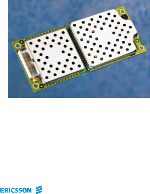
3.2 The M3090 Radio Modem............................................................... 9
3.3 Host Communication .....................................................................12
4 About Antennas......................................................................................... 13
4.1 The Functions of an Antenna......................................................... 13
4.2 Antenna Concepts .......................................................................... 14
4.3 The M3090 Antenna ...................................................................... 16
4.4 Antenna Suppliers.......................................................................... 17
5 Technical Data........................................................................................... 19
5.1 Physical Data.................................................................................. 19
5.2 Connectors and Logical Interfaces................................................. 20
5.3 Power Supply ................................................................................. 23
5.4 Environmental Specifications ........................................................ 26
5.5 Safety Specifications...................................................................... 28
5.6 Radio Specifications....................................................................... 29
5.7 External Antenna Specifications.................................................... 30
6 Host Requirements .................................................................................... 31
6.1 Host Environment .......................................................................... 31
6.2 Integrator’s Kit............................................................................... 32
6.3 Physical installation of the Radio Modem ..................................... 33
6.4 Selecting an Antenna...................................................................... 37
6.5 Connecting the Antenna................................................................. 37
6.6 Connecting the Radio Modem to the Host..................................... 38


Safety Advice 1
M3090 Integrator’s Manual, Doc.no: 19 817-KRD 102 303 Uen, Rev A
6DIHW\DGYLFHDQGRWKHUSUHFDXWLRQV
The M3090 radio modem should be handled like any other mobile radio station.
Therefore, you – the integrator – should read this information before integrating
the modem with your application.
6DIHW\
• The radio modem must not be used with or close to any medical life support
equipment.
• Used in proximity to personal medical electronic devices, such as
pacemakers or hearing aids, the modem may present a hazard. Make sure
that use of the modem is permitted; as a rule, radio transmitters must be
switched off at hospitals, on aeroplanes etc.
• The modem has no built-in fuse. To protect the power supply cables and
fulfil fire safety requirements, a fuse should be mounted as close to the
terminals of the power supply as possible.
• Never use the modem at a gas station, refuelling point, blasting area or other
explosive environment.
• If the antenna is to be mounted outdoors, consider protection from lightning.

2 M3090 Integrator’s Manual
M3090 Integrator’s Manual, Doc.no: 19 817-KRD 102 303 Uen, Rev A
3URGXFWFDUH
• Do not expose the radio modem to environmental or electrical loads beyond
the limits specified in FKDSWHU³7HFKQLFDO'DWD´. Any such exposure may
damage the modem.
• Make sure to connect the antenna EHIRUH the system connector. Operating
the modem without an antenna may cause severe damage.
• Do not connect more than one modem to a single antenna. Radio frequency
energy from the transmitter of one modem may damage another unit.
• Do not connect to the modem any component or product that is not
compatible with the M3090 interface as specified in this manual. Ericsson
does not warrant any defects, non-conformities and/or deviations caused by
such a connection.
Mismatched external components, such as improperly made connections or
incorrectly designed or installed antennas, may cause radiation limits to be
exceeded, which could lead to malfunction in the modem or the host
equipment.
• Operating the modem close to other electronic devices, such as antennas,
television sets or radios, may cause electromagnetic interference.
• Do not place the modem close to magnetic storage media, such as credit
cards, computer diskettes etc.
• Do not try to dismantle the modem, or you may lose your warranty. The
modem does not have any user-serviceable components.

About this Manual 3
M3090 Integrator’s Manual, Doc.no: 19 817-KRD 102 303 Uen, Rev A
$ERXWWKLV0DQXDO
3XUSRVHRIWKLV0DQXDO
This manual describes the M3090 radio modem and defines what is required
from the host equipment and the environment in which the modem is to be
integrated.
The manual also provides technical data and background information about
antennas and the Mobitex system.
:KR6KRXOG5HDGWKLV0DQXDO"
This manual is intended for engineers in OEM companies who plan and
implement the integration of the M3090 radio modem with various host
equipment for operation in a Mobitex network.
It is assumed that the reader is familiar with the basics of radio and
telecommunications technology.
In addition to this manual, most integration engineers will require the following
to start up and test an integrated radio modem successfully:
• the MASC (Mobitex Asynchronous Communication Protocol) chapter in
the Mobitex Interface Specification (MIS).
• an M3090 Integrator’s Kit (from Ericsson).

4 M3090 Integrator’s Manual
M3090 Integrator’s Manual, Doc.no: 19 817-KRD 102 303 Uen, Rev A
+RZWR8VHWKLV0DQXDO
To get an understanding of the basics of a Mobitex network and the function of
the M3090 radio modem, read FKDSWHU³,QWURGXFWLRQ´.
Readers who are not familiar with the basics of antenna selection and design
should also read FKDSWHU³$ERXW$QWHQQDV´.
The following two, FKDSWHU³7HFKQLFDO'DWD´ and FKDSWHU³+RVW
5HTXLUHPHQWV´, contain information that is useful when planning the integration
of the modem.
Information about type approval and type approval authorities, mainly in North
America, is presented in FKDSWHU³7\SHDSSURYDO´.
Finally, the ,QGH[ lists items in alphabetical order, with references to page
numbers.
4XHVWLRQVDQG&RPPHQWV
If you have any questions or comments regarding the contents of this manual,
please send them to:
Ericsson Mobile Data Design AB
Technical Assistance Centre
S:t Sigfridsgatan 89
S-412 66 Göteborg
SWEDEN
Fax: +46 31 703 6033
E-mail: mobitex.tac@erv.ericsson.se
About this Manual 5
M3090 Integrator’s Manual, Doc.no: 19 817-KRD 102 303 Uen, Rev A
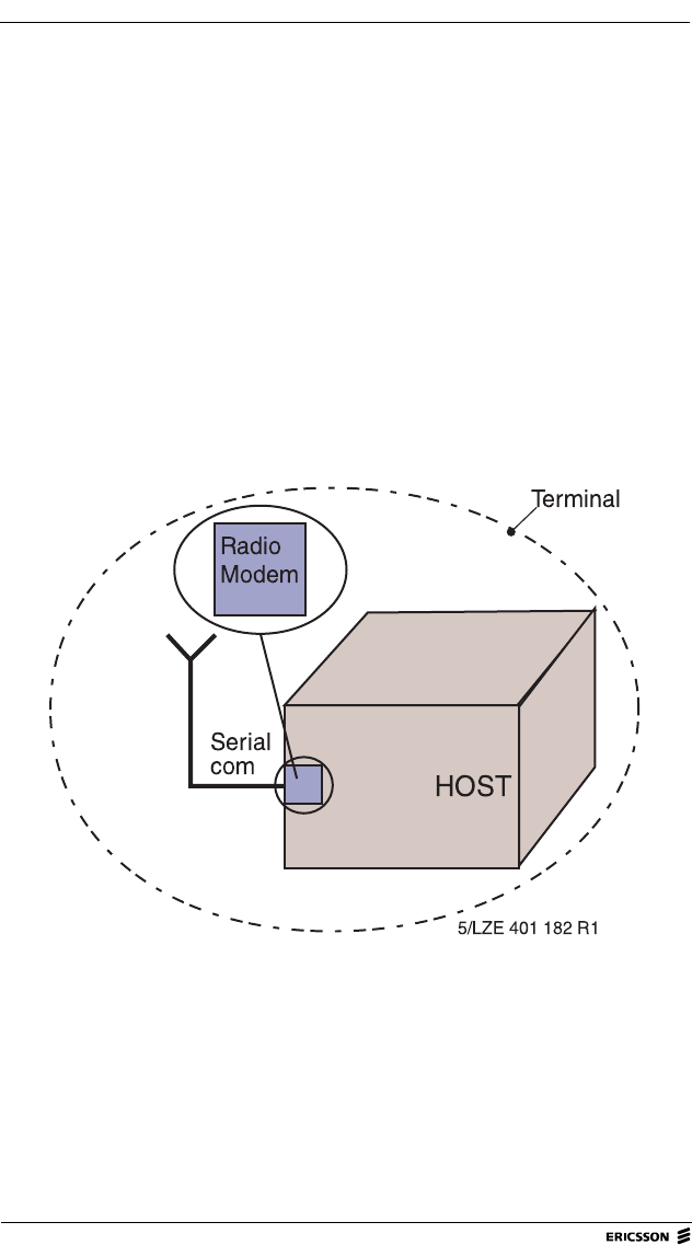
7HUPLQRORJ\
The following terminology is used in this manual:
• The M3090 wireless modem is called the UDGLRPRGHP.
• The data equipment which uses the radio modem to communicate with the
radio base station is called the KRVW.
• The data equipment and the radio modem, used as a single integrated unit,
is called the WHUPLQDO.
• An OEM company that integrates M3090 radio modems with various host
equipment is called an LQWHJUDWRU.
)LJXUH 7HUPLQRORJ\

6 M3090 Integrator’s Manual
M3090 Integrator’s Manual, Doc.no: 19 817-KRD 102 303 Uen, Rev A
5HIHUHQFHVDQG3URGXFWV
• Mobitex Interface Specification (MIS), LZBA 703 1001
• Data Communication over the telephone network. Recommendation V.24,
CCITT, Fascicle VIII.I, 1988
• M3090 Product Description, AE/LZT 123 2070
• M3090 Integrator’s Kit, KRY 901 46
Introduction 7
M3090 Integrator’s Manual, Doc.no: 19 817-KRD 102 303 Uen, Rev A
,QWURGXFWLRQ
This chapter introduces the Mobitex system, the M3090 radio modem and the
mode of communication between a radio modem and its host equipment.
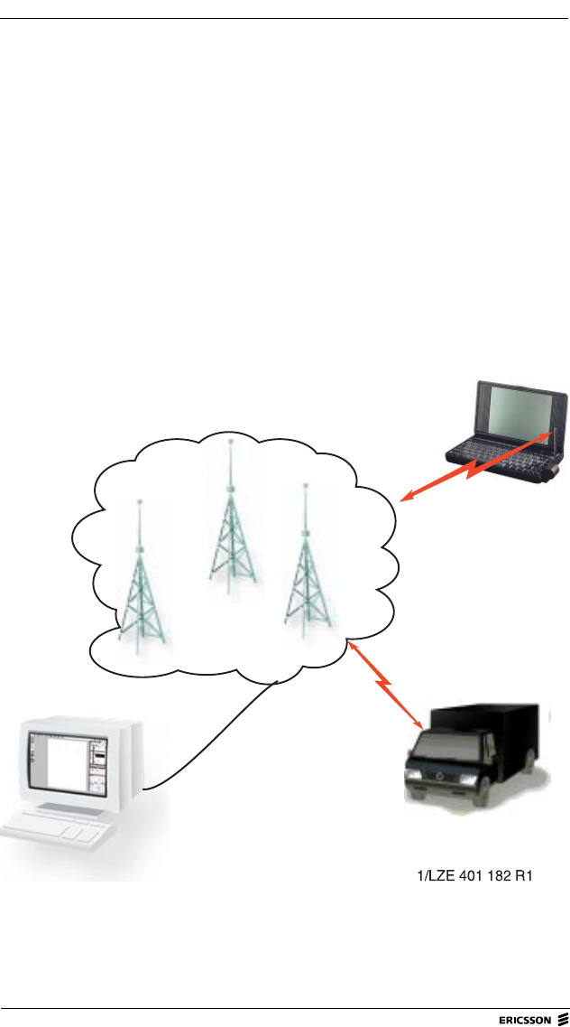
7KH0RELWH[1HWZRUN
The M3090 radio modem operates through a Mobitex network, a radio network
for data communication. The network consists, mainly, of exchanges, radio base
stations, fixed terminals and mobile terminals.
)LJXUH 0RELWH[QHWZRUNZLWKIL[HGDQGPRELOHWHUPLQDOV

8 M3090 Integrator’s Manual
M3090 Integrator’s Manual, Doc.no: 19 817-KRD 102 303 Uen, Rev A
)L[HGWHUPLQDOV
A fixed terminal is connected to the network by landline facilities.
0RELOHWHUPLQDOV
A mobile terminal communicates with radio base stations via a radio modem.
5DGLREDVHVWDWLRQVDQG([FKDQJHV
Radio base stations direct data to and from the fixed and mobile terminals in
their coverage area. If a radio base station receives data addressed to a mobile
or a fixed terminal outside its coverage area, the radio base station transfers the
data to the exchange to which it is connected. The exchange, in turn, transfers
the data to the radio base station that is in contact with the addressed terminal.
03$.V
Throughout the Mobitex network, data is transmitted and received in the form
of data packets, called MPAKs. Each MPAK includes addressee, sender and
user data (text and binary data), as well as certain control data.
An MPAK can contain a maximum of 512 bytes of user data.
Introduction 9
M3090 Integrator’s Manual, Doc.no: 19 817-KRD 102 303 Uen, Rev A
7KH05DGLR0RGHP
*HQHUDO
By running an application program on the host, a user can transmit and receive
data to and from the Mobitex network. The M3090 radio modem operates in
half duplex mode when communicating with the network, and in full duplex
mode when communicating with the host. The following radio frequencies can
be used:
1RWH National regulations may restrict the above frequency ranges
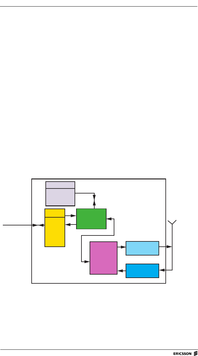
)XQFWLRQ%ORFNV
Transmitting frequency 896 - 902 MHz
Receiving frequency 935 - 941 MHz
)LJXUH 7KH0UDGLRPRGHPVPDMRUIXQFWLRQEORFNV
Memory
I/O port Micro-
controller
Transmitter
Receiver
M 3090
Data to and
from host
MPAK to
and from
network
6/LZE 401 182 R1
Digital
Signal
Processor
(DSP)
RS232
BIN IO
AD/DA
I2C
Flash
SRAM
E2PROM

10 M3090 Integrator’s Manual
M3090 Integrator’s Manual, Doc.no: 19 817-KRD 102 303 Uen, Rev A
7UDQVPLWWHU
The transmitter is turned on when the radio modem:
• Is about to become active in the network.
• Transmits data, i.e. MPAKs, to the radio base station.
• Acknowledges received MPAKs.
• Changes radio base stations; it then has to inform the network of the change,
this is called Roaming.
• Changes its operation mode, from power saving mode to express mode or
vice versa.
5HFHLYHU
Besides receiving MPAKs addressed to the host, the radio modem frequently
receives control signals from the network. These control signals are used to
select the radio base station with the strongest radio signal.
0LFURFRQWUROOHU
Using the Mobitex Asynchronous Communication Protocol (MASC), the micro
controller handles communication between the host and the Mobitex network.
The controller consists of a CPU, internal software which handles the MASC
protocol, and a radio protocol for communication with the network. For further
information about the MASC protocol, see the MASC Programmers Manual.
0HPRU\
The modem software is stored on a flash memory chip while an EEPROM is
used for configuration data.

Introduction 11
M3090 Integrator’s Manual, Doc.no: 19 817-KRD 102 303 Uen, Rev A
3RZHU
Power is supplied through the system connector. The required voltage is 6-9 V
DC (nominally 7.5 V).
3RZHU2SHUDWLQJ0RGHV
When the radio modem is powered, it operates in one of the following three
modes:
• sleep
• receiving
• transmitting
Unless communication within the Mobitex network is very intense, the radio
modem spends most of its time in the sleep mode. In this mode, the modem
waits for host requests and the air interface is inactive. The sleep mode is
entered whenever the radio modem is reset or powered on.
The radio modem enters receiving mode when:
• the power saving protocol says it is time to monitor the radio link (power
saving mode)
• the host requests that the radio link be constantly monitored (express mode)
• data from the network is expected
• the host requests access to the network.
When data needs to be transmitted, the radio modem enters transmitting mode.
The time spent in this mode is minimized in order to reduce power
consumption.
$QWHQQD
The host equipment must provide an external antenna. The antenna is connected
to the radio modem's antenna connector of the SMT type (from M/A Com, see
&KDSWHU).

12 M3090 Integrator’s Manual
M3090 Integrator’s Manual, Doc.no: 19 817-KRD 102 303 Uen, Rev A
+RVW&RPPXQLFDWLRQ
*HQHUDO
The radio modem communicates with the host equipment through the system
connector. A 30 pin MINI-FIX connector (from ODU) is used as a physical
interface.
$SSOLFDWLRQ6RIWZDUH
The integrator may develop application software (and the MASC/MPAK
driver) or use a MASC/MPAK API, which can be bought from Ericsson as a part
of the M3090 Integrator’s Kit.
6HULDO&RPPXQLFDWLRQ
The M3090 radio modem uses serial communication. The modem allows full
duplex serial communication with the host through the interface in accordance
with the CCITT V.24 standard (where applicable).
The radio modem has functions for handling overrun, parity and framing errors.
It also supports all the baud rates used by the MASC protocol.

About Antennas 13
M3090 Integrator’s Manual, Doc.no: 19 817-KRD 102 303 Uen, Rev A
$ERXW$QWHQQDV
This chapter contains some antenna-technology basics. It is intended to help
integrators with little previous experience to select an antenna for the host with
which the M3090 radio modem is to be integrated.
If a non-standard antenna has to be designed, please consult an antenna
specialist.
7KH)XQFWLRQVRIDQ$QWHQQD
An antenna has two functions:
• to emit radio waves (transmission)
• to pick up radio waves (reception).
The antenna does this more or less efficiently, depending on:
• the type of antenna
• the placement of the antenna
• the environment in which the antenna is used.
+DOIZDYHDQG4XDUWHUZDYH$QWHQQDV
Two types of antennas are commonly used for mobile radio terminals:
• half-wave antennas
• quarter-wave antennas.
Both are omni-directional antennas, that is, they radiate energy in all directions.
However, a half-wave antenna is less sensitive to external influences
(movements in its vicinity etc.) than a quarter-wave antenna.

14 M3090 Integrator’s Manual
M3090 Integrator’s Manual, Doc.no: 19 817-KRD 102 303 Uen, Rev A
$QWHQQD/HQJWKV
The following lengths are typical for half-wave and quarter-wave antennas in
the frequency range that the M3090 radio modem uses. The lengths shown can
vary somewhat, depending on the material that surrounds the core of the
antenna.
6KRUWHQHG$QWHQQDV
A shortened antenna is even shorter than a quarter-wave antenna. It can be
designed to have characteristics that are nearly as good as those of a full-length
antenna.
$QWHQQD&RQFHSWV
The following sections present some fundamental concepts with regard to
antennas.
$QWHQQD*URXQG3ODQH
An antenna ground plane is an area under the antenna that is connected to
ground and horizontal, flat and sufficiently wide. An antenna with a ground
plane will function more efficiently.
It is especially important that quarter-wave antennas have a ground plane.
3RODUL]DWLRQ
Radio waves radiate parallel to the antenna. The best reception is achieved when
the receiving antenna is parallel to the transmitting antenna.
The antennas of Mobitex radio base stations are vertical, which means that the
radio waves are vertically polarized.
Frequency range Half-wave antenna length Quarter-wave antenna length
890 to 960 160 mm 80 mm

About Antennas 15
M3090 Integrator’s Manual, Doc.no: 19 817-KRD 102 303 Uen, Rev A
$QWHQQD*DLQ
Antenna gain is defined as the ratio between the antenna’s radiant intensity and
that of a reference antenna which experiences no loss, but has the same power
input.
Antenna gain is usually expressed in dBi, the i indicating that the calculated
radiation from an isotropic antenna has been used as a reference. The isotropic
antenna has the same radiant intensity in all directions, that is, the radiation
pattern is spherical.
1RWH In data sheets, an antenna’s maximum gain is often expressed in
dBd without any reference to direction. The (second) d in dBd
indicates that the calculated radiation from a single half-wave
dipole antenna is used as a reference.
The relationship between dBd and dBi is described in )LJXUH.
(QYLURQPHQWDO,QIOXHQFHV
The antenna must have sufficiently effective radiation for the radio terminal to
be able to communicate with a radio base station. The maximum range might
be up to 15 or 20 kilometres depending on:
• what frequency range the Mobitex network uses (the higher the frequency,
the shorter the maximum distance);
• whether the terminal is situated in a built-up area or in open country.
In an urban area, attenuation caused by buildings, walls and other obstacles has
to be considered. Too large or too many obstacles around the antenna might
mean that the radio terminal cannot establish a contact with the radio base
station. In such a case, the antenna is said to be in a radio shadow.
)LJXUH 5HODWLRQVKLSEHWZHHQG%LDQGG%G
dBd = dBi + 2.15 dB
P(d) = P(i) x 1.64

16 M3090 Integrator’s Manual
M3090 Integrator’s Manual, Doc.no: 19 817-KRD 102 303 Uen, Rev A
7KH0$QWHQQD
An antenna cable is required to connect an antenna to the M3090 modem’s
antenna connector, that is, a detached antenna is used. A detached antenna
should consist of three parts: the antenna rod, an impedance matching network
and a coaxial cable with a connector.
A detached antenna may often be more effective than other types, especially
when the radio terminal is used in a vehicle.
$QWHQQD5RG
A half-wave dipole antenna should preferably be used. It should be low-weight
and as short as possible, while still complying with the antenna specifications.
Antenna specifications are found in FKDSWHU³7HFKQLFDO'DWD´.
$QWHQQD&DEOH
A cable with connectors at each end is required to connect a detached antenna
to the radio modem. Use a low-loss cable with high-quality connectors to avoid
loss of signal power between the antenna and the modem. Both the cable and
the connectors must have an impedance equal to that of the antenna connector
of the radio modem, that is, 50 .
The antenna cable should be flexible to allow easy fitting of the antenna in a
vertical position.
Poor contact between, or mismatching of, the connectors may cause a partial
reflection of the signal from the radio modem. The ratio between the modem’s
output power and the power reflected from the antenna is defined as the Voltage
to Standing Wave Ratio (VSWR) and is calculated using the formula shown in
)LJXUH.
Ω
About Antennas 17
M3090 Integrator’s Manual, Doc.no: 19 817-KRD 102 303 Uen, Rev A
To get an effective communication, a VSWR of 2 or less is recommended for
the antenna, see FKDSWHU³7HFKQLFDO'DWD´.
$QWHQQD6XSSOLHUV
The integrator can use an antenna supplied by a third party or design one that
complies with the antenna specifications in FKDSWHU³7HFKQLFDO'DWD´.
The following antennas perform well and have been used during certification:
1RWH The above antennas fulfil FCC requirements for RF power
emission into nearby human bodies (SAR) with a good margin
also in worst-case situations. However, it is recommended that
the antenna is installed so that there, in normal use, is a distance
of at least 5 cm (2 inch) to human bodies.
If any other than the above antennas is used, the integrator is recommended to
verify that applicable emissions standards are complied with.
)LJXUH 7KHIRUPXODIRUFDOFXODWLQJ96:5
Supplier: Model: Ericsson Product
No: Comment:
Carant1SMA900 KRE 101 1132 Omni-directional w/ SMA male,
see )LJXUH
Cushcraft2SN8962N N/A Omni-directional w/ standard
RG58 cable and N-connector
VSWR
1ReflectedPower
OutputPower
------------------------------------------+
1ReflectedPower
OutputPower
------------------------------------------–
--------------------------------------------------------
=

18 M3090 Integrator’s Manual
M3090 Integrator’s Manual, Doc.no: 19 817-KRD 102 303 Uen, Rev A
)LJXUH 7KH60$DQWHQQDIURP&DUDQW
1Carant Antenn AB, PO Box 4064, S-182 04 Enebyberg, Sweden
Tel: +46 8-792-92-00, Fax: +46 8 792 06 77, E-mail: market.dept@carant.se
http://www.carant.se
2Cushcraft Corporation, 48 Perimeter Rd., Manchester N.H., 03103, U.S.A.
Tel: +1 603-627-7877, E-mail: sales@cushcraft.com
http://www.cushcraft.com/
12/LZE 401 182 R1
20 M3090 Integrator’s Manual
M3090 Integrator’s Manual, Doc.no: 19 817-KRD 102 303 Uen, Rev A
&RQQHFWRUVDQG/RJLFDO,QWHUIDFHV
Antenna connector SMT socket (50 )
Supplier: M/A Com,
http://www.macom.com,
Product No. 2367 - 5002 - 54
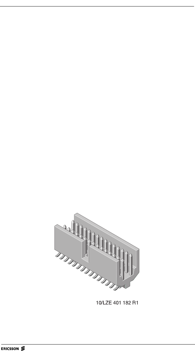
System connector 30-pin MINI-FIX connector.
For pin configuration, see &KDSWHU
and )LJXUH below.
Supplier: ODU,
http://www.odu.de,
Product No. 515.568.035.030.050
Mating connectors - System connector
Board-board ODU, Product No. 525.041.035.030.xxx
Board-cable
- Socket
- Locking clip ODU, Product No. 525.060.035.030.xxx
ODU, Product No. 515.067.730.700.000
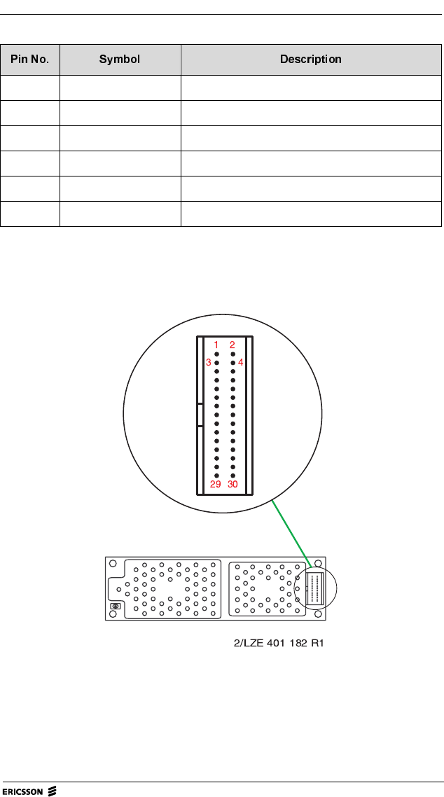
)LJXUH 7KHUDGLRPRGHPVV\VWHPFRQQHFWRU
Ω
Technical Data 21
M3090 Integrator’s Manual, Doc.no: 19 817-KRD 102 303 Uen, Rev A
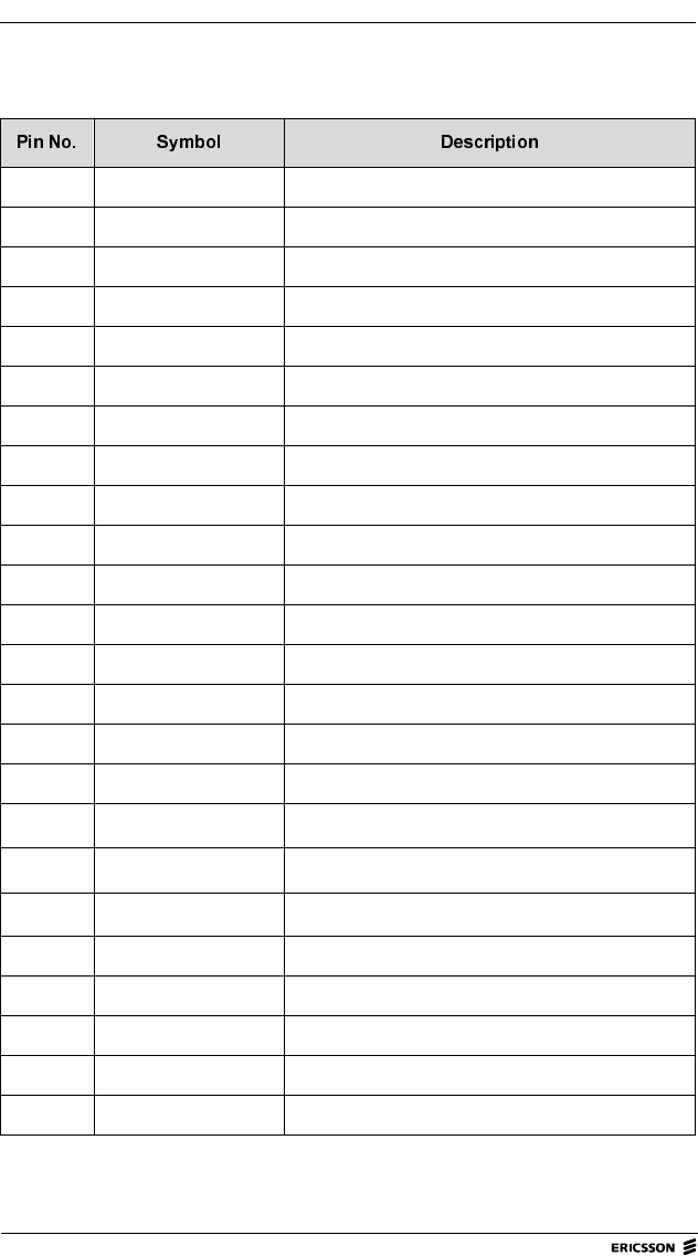
6\VWHP&RQQHFWRU3LQFRQILJXUDWLRQ
1 Supply voltage Incoming feed (6-9 V)
2 Supply voltage Incoming feed (6-9 V)
3 Test Leave unconnected
4 Reset Reset (input; active low)
5 Spare Reserved
6 RD Serial data from modem
7 TD Serial data to modem
8 RTS Request To Send (input)
9 CTS Clear To Send (output)
10 DTR Data Terminal Ready (input)
11 DCD Data Carrier Detect (output)
12 REF_CLK 19.2 MHz Reference Clock (output)
13 GND Ground
14 GND Ground
15 Spare Reserved
16 Spare Reserved
17 SCL I2C Clock
18 SDA I2C Data
19 VDD Logical reference +3.3 V
20 BIN1_IN Binary1 IN
21 BIN2_IN Binary2 IN
22 BIN3_OUT Binary3 OUT
23 BIN4_OUT Binary4 OUT
24 WAKE/Systemstart Switch main regulator ON (input; active low)
22 M3090 Integrator’s Manual
M3090 Integrator’s Manual, Doc.no: 19 817-KRD 102 303 Uen, Rev A
6\VWHP&RQQHFWRU3LQRULHQWDWLRQ
25 GND Ground
26 DOWNLOAD Download
27 AD_OUT User analog OUT
28 GND Ground
29 GND Ground
30 AD_IN User analog IN
)LJXUH 6\VWHPFRQQHFWRUSLQRULHQWDWLRQ
Technical Data 23
M3090 Integrator’s Manual, Doc.no: 19 817-KRD 102 303 Uen, Rev A
3RZHU6XSSO\
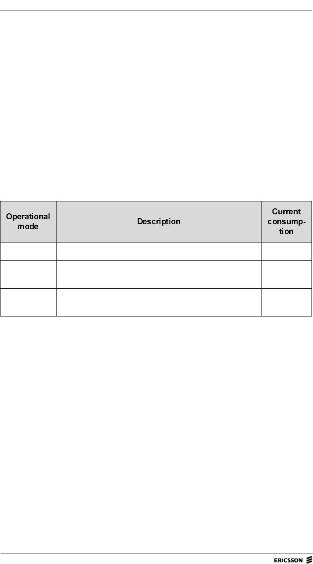
&XUUHQWFRQVXPSWLRQ
7RWDOFXUUHQW
Operating voltage 6 - 9 V (7.5 V nominal)
Current consumption See &KDSWHU below
Maximum ripple See &KDSWHU below
DC characteristics, System Connector See &KDSWHU below
Sleep mode The radio modem’s logic part is on and the radio part is off. 85 mA
Receiving
mode
The modem is on and receiving data or control signals from
the Mobitex network.
<200 mA
Transmitting
mode
The modem is on and transmitting data to the Mobitex
network
1150 mA
(2 A peak)
24 M3090 Integrator’s Manual
M3090 Integrator’s Manual, Doc.no: 19 817-KRD 102 303 Uen, Rev A
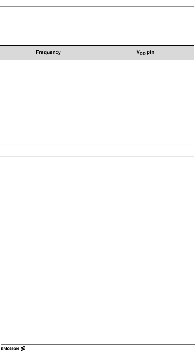
0D[LPXPULSSOH
Ripple on power supply voltage at system connector, maximum values:
< 100 Hz 150 mVRMS
100 Hz to 10 kHz 100 mVRMS
10 to 440 kHz 50 mVRMS
440 to 460 kHz 5 mVRMS
460 kHz to 94 MHz 50 mVRMS
94 to 96 MHz 1 mVRMS
96 to 850 MHz 50 mVRMS
850 to 950 MHz 1 mVRMS
Technical Data 25
M3090 Integrator’s Manual, Doc.no: 19 817-KRD 102 303 Uen, Rev A
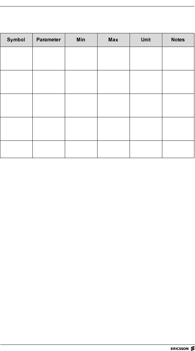
'&FKDUDFWHULVWLFVIRUWKH6\VWHP&RQQHFWRU
VDD = 3.3 V
VIL Input
Voltage,
Low
00.8V
VIH Input
Voltage,
High
2.0 VDD V
VOL Output
Voltage,
Low
0 0.5 V Valid if IOL
< 1mA
VOH Output
Voltage,
High
2.7 VDD V Valid if IOH
< 1mA
CIN Input
Capacitance
100 pF
26 M3090 Integrator’s Manual
M3090 Integrator’s Manual, Doc.no: 19 817-KRD 102 303 Uen, Rev A
(QYLURQPHQWDO6SHFLILFDWLRQV
The M3090 radio modem has been tested in accordance with the IEC 60068,
IEC 61000 and ISO 7816 standards.
The environmental tests are divided into four groups:
• Transport/storage
• Climatic
• Mechanical
• Electrical
The modem satisfies the requirements specified under each group below.
7UDQVSRUWVWRUDJH
Tested unit: Radio modem in delivery package, non-operating (VDD=0).
&OLPDWLF
Tested unit: Radio modem, operating
Temperature range -40 to +70 C
Relative humidity 5-95%
X-ray exposure Dose: 0.1 Gy
Free fall 1 m drop to concrete surface
Temperature range -25 to +65 C
Relative humidity 5-95%
°
°

Technical Data 27
M3090 Integrator’s Manual, Doc.no: 19 817-KRD 102 303 Uen, Rev A
0HFKDQLFDO
Tested unit: Radio modem, non-operating (supply voltage=0) unless otherwise
stated below.
Random
vibration (operating) 10-195 Hz
195-205 Hz
205-500 Hz
(60 min/axis)
0.03 g2/Hz g2/Hz
0.01 g2/Hz
Sinus vibration,
endurance 10-500 Hz, 1 octave/min,
acceleration 15 g,
(10 cycles/axis)
Sinus vibration,
radio resonance
investigation
(operating) 10-150 Hz
150-500 Hz
500-2000 Hz
1 octave/
5 min
(1 cycle/axis)
20 m/s2
10 m/s2
5 m/s2
Shock Peak acceleration 100 g,
pulse duration 6 ms (half-sine)
(6 shocks/axis)
Bump (operating) Peak acceleration 15 g,
pulse duration 6 ms (half-sine)
(1000 bumps/axis)
Free fall 1 m drop to steel surface
(2 falls on each face)
0
.03 0.01→
amplitude 1 mm≤

28 M3090 Integrator’s Manual
M3090 Integrator’s Manual, Doc.no: 19 817-KRD 102 303 Uen, Rev A
(OHFWULFDO
Tested unit: Radio modem, operating
6DIHW\6SHFLILFDWLRQV
Components and materials comply with the EN60950 standard (European
Standards – CENELEC – Safety of Information Technology Equipment,
including electrical business equipment).
Electrostatic discharge contact 4.0 kV
air 8.0 kV (antenna)
Immunity, radiated electromagnetic
field Severity 10 V/m
Ripple See “Maximum ripple” on page 24

Technical Data 29
M3090 Integrator’s Manual, Doc.no: 19 817-KRD 102 303 Uen, Rev A
5DGLR6SHFLILFDWLRQV
Transmitter frequencies 896.0 to 902.0 MHz1
Receiver frequencies 935.0 to 941.0 MHz1
Data transfer rate 8 kbps (gross rate)
Channel separation 12.5 kHz
Channel selection automatic roaming
Frequency stability 1.5 ppm
Receiver sensitivity -115 dBm
Modulation modified GMSK
Transmitter output 2 W maximum;
Power attenuation in 3 dB steps, down
to -21 dB relative to maximum output.
1National regulations may restrict this frequency range.
( 1.35 kHz)≈
30 M3090 Integrator’s Manual
M3090 Integrator’s Manual, Doc.no: 19 817-KRD 102 303 Uen, Rev A
([WHUQDO$QWHQQD6SHFLILFDWLRQV
Antenna impedance (nominal) 50
Frequency range 890 - 960 MHz
Recommended antenna gain 2 dBi
Voltage to Standing Wave Ratio
(VSWR) max. 2
Recommended antenna length approx. 160 mm (half-wave)
Polarization vertical
Half-power beam-width,
horizontal 80
vertical 360
Recommended cable length 0.75 m
Connector type (on radio modem) SMT (from M/A Com),
see )LJXUH
Humidity max. 95% RH
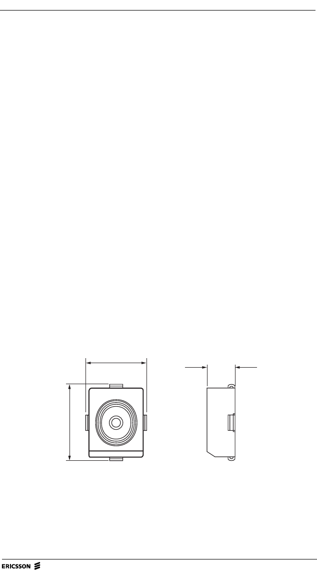
)LJXUH 7KHUDGLRPRGHPV607DQWHQQDFRQQHFWRU
Ω
°
°
4.5 mm
5.0 mm
7/LZE 401 182 R1
2.1 mm

Host Requirements 31
M3090 Integrator’s Manual, Doc.no: 19 817-KRD 102 303 Uen, Rev A
+RVW5HTXLUHPHQWV
This chapter presents the requirements, technical and environmental, that have
to be considered when integrating M3090 radio modems with host equipment.
+RVW(QYLURQPHQW
The hostmust provide a physical environment where the radio modem is not
exposed to temperatures, humidity etc. beyond what it is designed for.
Refer to FKDSWHU³7HFKQLFDO'DWD´ for detailed requirements regarding:
• Physical Data
• Connectors and Logical Interfaces
• Power Supply
• Environmental Specifications

32 M3090 Integrator’s Manual
M3090 Integrator’s Manual, Doc.no: 19 817-KRD 102 303 Uen, Rev A
,QWHJUDWRU¶V.LW
To facilitate the integration of the M3090 radio modem, Ericsson supplies an
Integrator’s Kit (Product No. KRY 901 46). The kit contains:
• The MobiOne configuration software (Windows 95/NT compatible) for the
setting of a Mobitex Access Number, country code(s) etc. before the modem
is used in a Mobitex network.
• MASC-Driver, with source code.
• IP-Gateway/MASC Demo “Hello World”.
• 1 Interface Converter, 3.3V-CMOS / V.28, ROA 117 9629.
•1 Antenna.
• Integration directives.
Host Requirements 33
M3090 Integrator’s Manual, Doc.no: 19 817-KRD 102 303 Uen, Rev A
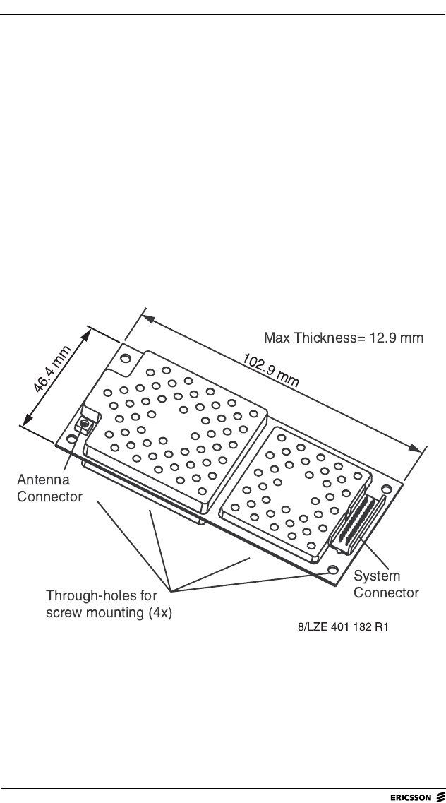
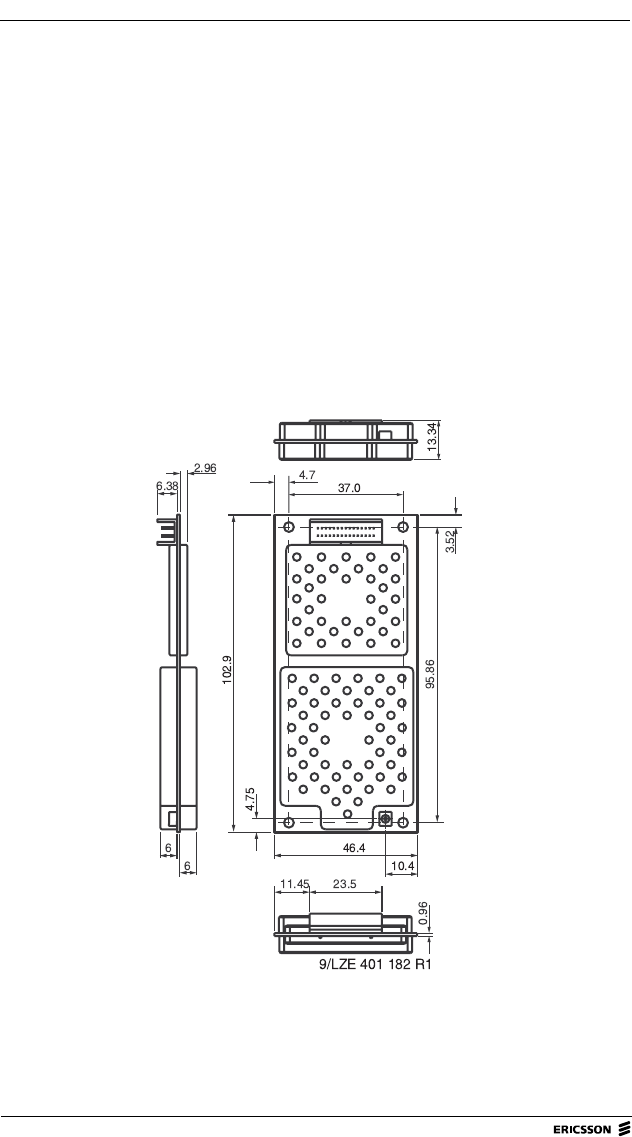
3K\VLFDOLQVWDOODWLRQRIWKH5DGLR0RGHP
Place the radio modem so that it is protected from pollution, vibrations and
shock. Avoid placing the modem close to any circuit that is likely to cause
interference. Secure the modem correctly to prevent it from falling out when
transporting or moving the host equipment.
The antenna should preferably be fitted so that it is always vertical, regardless
of the host equipment’s position.
Make sure that the radio modem’s antenna and system connectors can be
accessed when the modem is fixed in the host equipment.
)LJXUH 'LPHQVLRQVRIWKH0UDGLRPRGHP
34 M3090 Integrator’s Manual
M3090 Integrator’s Manual, Doc.no: 19 817-KRD 102 303 Uen, Rev A
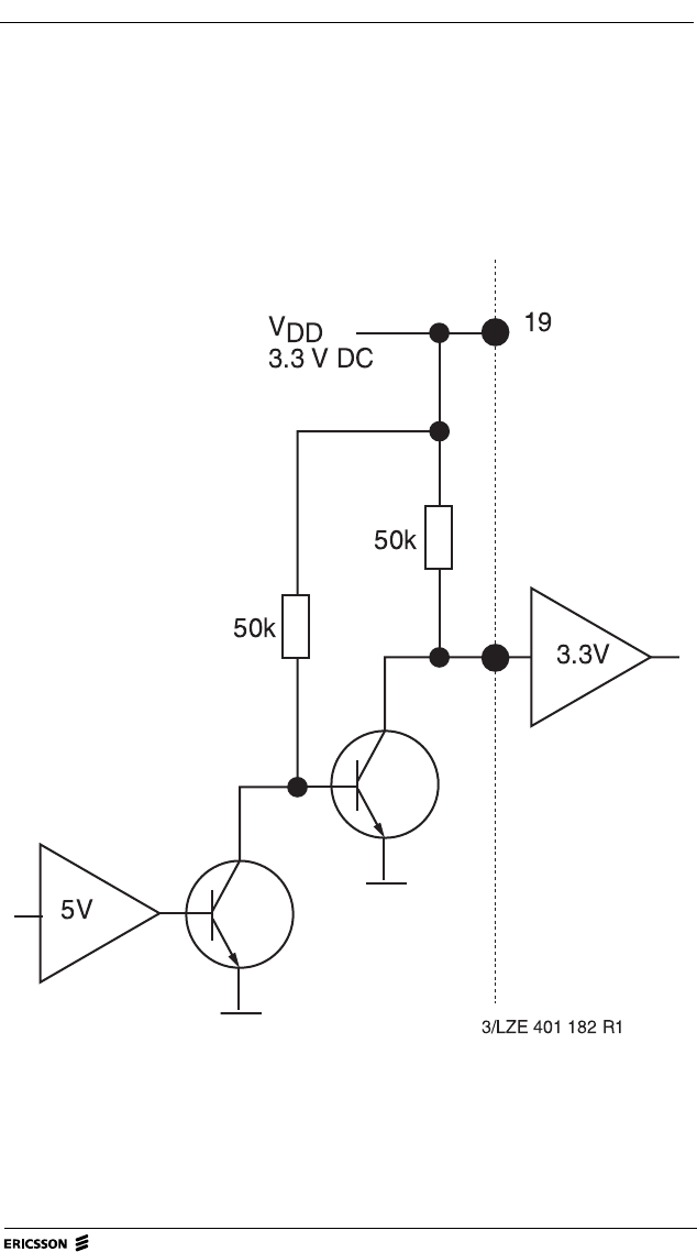
9WR9&RQYHUVLRQ
If the host equipment uses 5 V logic, the electrical interface needs to be
converted to 3.3 V. )LJXUH below shows an example of how to implement
such a conversion.
)LJXUH 9WR9&RQYHUVLRQ
Host Requirements 35
M3090 Integrator’s Manual, Doc.no: 19 817-KRD 102 303 Uen, Rev A
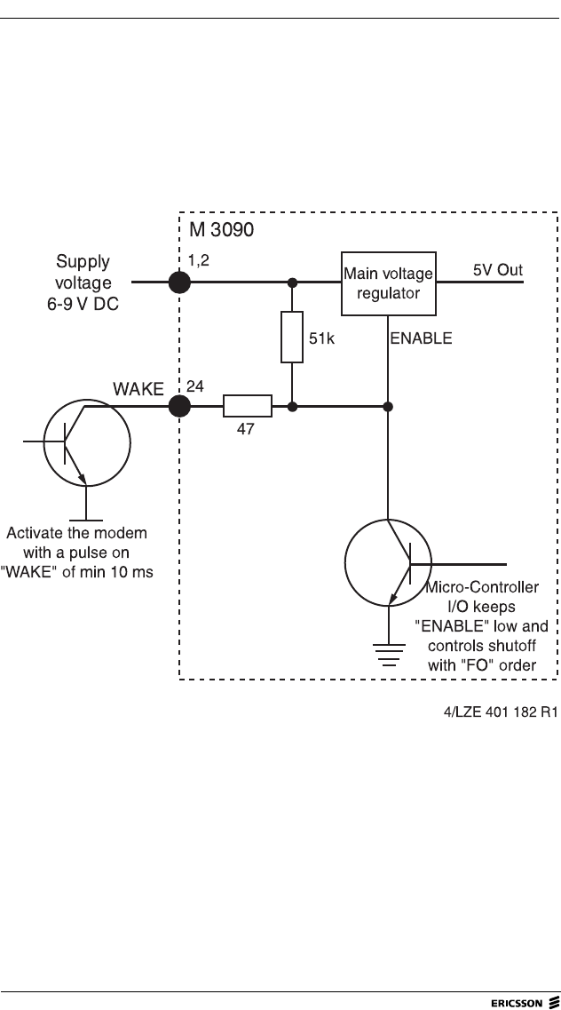
212))IXQFWLRQ
An ON/OFF function can be implemented using standard MASC-commands,
see )LJXUH.
Start the modem by grounding pin 24 for a minimum of 10 mS (“WAKE” – pin
24 – is active low).
Shut the modem off using the “FO” MASC-command. When “FO” is sent,
“WAKE” must be high. )LJXUH shows an example of how to implement this
using an Open Collector Connection. A relay or a switch can also be used.
)LJXUH ([DPSOHRIKRZWRLPSOHPHQWDQ212))IXQFWLRQ

36 M3090 Integrator’s Manual
M3090 Integrator’s Manual, Doc.no: 19 817-KRD 102 303 Uen, Rev A
&RROLQJ
Normally, no special measures are needed to cool M3090 radio modems.
However, if ambient temperature exceeds +65 C (see &KDSWHU.), cooling
will be required, otherwise the modem may over-heat and lose contact with the
network.
The heat dissipation of an M3090 radio modem varies depending on the volume
of data being transmitted. In normal use, when the modem transmits less than
1% of the time, the power consumption is less than 300 mW.
*URXQGLQJ
The M3090 radio modem card does not need to be grounded beyond what is
provided through the system connector.
However, it is recommended that the antenna connector be grounded, by
grounding the fixing screws. This will:
• improve the gain of the antenna;
• make the radio modem less sensitive to electrostatic discharge (ESD).
(6'3URWHFWLRQ
M3090 radio modems are sensitive to electrostatic discharge. Use normal
precautions to prevent ESD.
6KLHOGLQJ
M3090 radio modems fulfil the shielding requirements set by the regulatory
approval authorities in the USA and Canada. Therefore, additional shielding of
the modem is normally not necessary.
°

Host Requirements 37
M3090 Integrator’s Manual, Doc.no: 19 817-KRD 102 303 Uen, Rev A
6HOHFWLQJDQ$QWHQQD
The antenna must be designed for the frequency range used by the radio
modem. The antenna must have the same impedance as the card’s antenna
connector, otherwise the transmitter’s output power will be reduced. For
information on radio frequencies and connector data, see FKDSWHU³7HFKQLFDO
'DWD´.
Perform the tests described – under Integration Tests – in the Integrator’s Kit to
find out whether the selected antenna suits the host in question. If tests show that
the antenna cannot be used, it might be helpful to read FKDSWHU³$ERXW
$QWHQQDV´.
If a non-standard antenna has to be designed, consult an antenna specialist to
make sure that all requirements are fulfilled.
&RQQHFWLQJWKH$QWHQQD
*HQHUDO
The M3090 radio modem must be equipped with an antenna that connects to the
modem via an antenna cable.
If possible, mount the antenna so that it is vertical at all times.
([WHUQDO$QWHQQD7HVW
An external antenna must comply with the specifications in FKDSWHU
³7HFKQLFDO'DWD´. Compliance should be verified by performing the tests
described in the Integrator’s Kit.

38 M3090 Integrator’s Manual
M3090 Integrator’s Manual, Doc.no: 19 817-KRD 102 303 Uen, Rev A
&RQQHFWLQJWKH5DGLR0RGHPWRWKH+RVW
Taking customary precautions against ESD, proceed as follows:
1. Mechanically fix the radio modem to the host.
2. Connect the antenna cable to the modem’s antenna connector. If a separate
antenna cable is used, make sure that the antenna rod is also connected.
1RWHOperating the modem without an antenna may cause severe
damage.
3. Connect the male system connector plug to the socket on the modem.

Type-approval 39
M3090 Integrator’s Manual, Doc.no: 19 817-KRD 102 303 Uen, Rev A
7\SHDSSURYDO
Any two-way communication radio, such as the M3090 radio modem, must be
type-approved by the appropriate authorities before it can be sold and used in a
country. Most countries have their own national bodies for type-approvals, but
a number of European Community member countries share a common
authority.
These authorities grant type-approvals to radios that have been successfully
tested by a certified radio test laboratory. The tests performed show if the radio
complies with the standards specified by the type-approval authorities.
5HTXLUHPHQWVLQWKH86$
&RPSOLDQFHDQGW\SHDSSURYDOQXPEHU
The M3090 radio modem complies with applicable radio standards in the USA.
Do not modify the M3090 modem, or connect to it any component or product
that is not compatible with the M3090 interface as specified in this manual.
Ericsson does not warrant any defects, non-conformities and/or deviations
caused by such actions.
The modem has been issued with a type-approval number, that can be retrieved
at:
http://www.fcc.gov/
Federal Communications
Commission (FCC)
1919 M Street NW
Washington D.C. 20554
40 M3090 Integrator’s Manual
M3090 Integrator’s Manual, Doc.no: 19 817-KRD 102 303 Uen, Rev A
9HULILFDWLRQDQGODEHOOLQJ
Compliance with applicable standards must be verified by the manufacturer of
the host equipment and stated on the integrated product. The type-approval
information for the radio modem must also be stated.
7KH0RGHP
The radio modem is delivered with the required type-approval information
shown on a label applied to it, see )LJXUH.
7KH0RGHP¶V'HOLYHU\3DFNDJH
The radio modem is delivered in a package marked as shown in )LJXUH.
)LJXUH Label applied to the radio modem.
)LJXUH Label for the modem’s delivery package.
KRD 102 303
FCC ID:
R
M3090
9700769
999M3090-Mobitex
15/LZE 401 182 R1
13/LZE 401 182 R1
with FCC Standards
Tested to Comply
FOR HOME OR OFFICE USE
M3090 KRD 102 303

Type-approval 41
M3090 Integrator’s Manual, Doc.no: 19 817-KRD 102 303 Uen, Rev A
7KH3URGXFW
The integrated product should have a label following the format shown in
)LJXUH.
In addition to the above label, the product should have a sticker with a text that
identifies the built-in radio device, such as :
“This device contains radio equipment
FCC ID XXXM3090-Mobitex”
)LJXUH 6SHFLPHQODEHOIRUWKHLQWHJUDWHGSURGXFW
Trade Name
FOR HOME OR OFFICE USE
Assembled From
(Complete System Not Tested)
14/LZE 401 182 R1
Tested Components
Model Number

42 M3090 Integrator’s Manual
M3090 Integrator’s Manual, Doc.no: 19 817-KRD 102 303 Uen, Rev A

,QGH[
A
antenna 13
cable 16
connecting 37
connector 20
connector type 30
functions 13
gain 15
ground plane 14
impedance 30
length 14
polarization 14
rod 16
selecting 37
suppliers 17
application software 12
B
base station 8
beam-width, half-power 30
C
channel
selection 29
separation 29
connecting modem to host 38
connectors and logical interfaces 20
cooling 36
current consumption 23

M3090 Integrator’s Manual, Doc.no: 19 817-KRD 102 303 Uen, Rev A
ii (v) M3090 Integrator’s Manual
D
data transfer rate 29
DC characteristics, system connector 25
E
electrical interface, conversion from 5 V 34
electromagnetic field, immunity 28
electrostatic discharge 28
environmental specifications 26
electromagnetic field, immunity 28
electrostatic discharge 28
free fall 26, 27
relative humidity 26
shock 27
temperature range 26
vibration 27
X-ray exposure 26
Ericsson
to contact 4
ESD protection 36
exchange 8
explosive environment 1
F
fixed terminal 8
free fall 26, 27
frequencies, transmitter/receiver 29
frequency stability 29
fuse 1

M3090 Integrator’s Manual, Doc.no: 19 817-KRD 102 303 Uen, Rev A
Index iii (v)
G
gain, antenna 15
ground plane, antenna 14
grounding 36
H
half-power beam-width 30
host
communication 12
definition 5
Requirements 31
I
integrator, definition 5
M
medical life support equipment, use with 1
micro controller 10
mobile terminal 8
Mobitex network 7
modulation 29
MPAK 8
O
ON/OFF function 35
operating voltage 23

M3090 Integrator’s Manual, Doc.no: 19 817-KRD 102 303 Uen, Rev A
Index iv (v)
P
personal medical electronic devices, use with 1
physical data 19
physical installation 33
pin configuration, system connector 21
pin orientation, system connector 22
polarization, antenna 14
power
operating modes 11
power supply 23
current consumption 23
maximum ripple 24
operating voltage 23
precautions 1
product care 2
Q
questions and comments 4
R
radio base station 8
radio specifications 29
range, maximum 15
receiver 10
frequencies 29
sensitivity 29
relative humidity 26
ripple, maximum 24

M3090 Integrator’s Manual, Doc.no: 19 817-KRD 102 303 Uen, Rev A
Index v (v)
S
safety advice 1
safety specifications 28
shielding 36
shock 27
system connector 20
T
technical data 19
temperature range 26
terminal, definition 5
terminology 5
transfer rate, data 29
transmitter 10
frequencies 29
output 29
type-approval 39
labelling 40
V
vibration 27
Voltage to Standing Wave Ratio 16, 30
voltage, operating 23
VSWR 30
calculating 16
X
x-ray exposure 26