Escort orporated RT75 Radar Detector User Manual
Escort Incorporated Radar Detector
Manual
(FRONT COVER)
Harley designed cover
ROAD TECH 75 DETECTOR

Page 2
Congratulations!
Your new Road Tech 75 detector is the most advanced custom motorcycle-
mounted radar detector available.
The Road Tech 75 detector includes full X, K, SuperWide Ka, including new
“POP” mode, radar protection, Laser, Digital Signal Processing for superior
range and improved anti-falsing, our patented Mute and AutoMute, audible
and visual band alerts, and all the performance you’d expect from Escort.
In addition, the new Road Tech 75 Detector introduces a new level of open-
road performance and motorcycle specific features.
• Turbo-Charged radar receiver for long-range warning
• Multiple laser sensors for advanced laser range
• Left-hand design for easy access while you ride
• Exclusive EZ-Programming lets you instantly set 8 features
• Exclusive AutoSensitivity mode, plus “Highway” and “City” settings
• 280 LED Ultra-bright Text-Matrix display for easy to read messages
• Exclusive ExpertMeter tracks and displays up to 8 radar signals
• Exclusive VG-2 Alert/Auto Shutoff
If you’ve used a radar detector before, a review of the “Quick Reference
Guide” on page 4, and the “Customize Road Tech with EZ Programming” on
page 12 will briefly explain the new features.
If this is your first detector, please read the manual in detail to get the most out
of your new Road Tech 75 Detector.
Please ride safely.
Laws and regulations regarding the ownership and operation of radar detec-
tors vary from place to place. Check state and local laws and regulations.
FCC NOTE:
Modifications not expressly approved by the manufacturer could void
the user’s FCC granted authority to operate the equipment.

Page 3
Table of Contents
Congratulations! . . . . . . . . . . . . . . . . . . . . . . . . . . . . . . . . . . . . . . . . . . . . 2
Quick Reference Guide. . . . . . . . . . . . . . . . . . . . . . . . . . . . . . . . . . . . . . . 4
Installation . . . . . . . . . . . . . . . . . . . . . . . . . . . . . . . . . . . . . . . . . . . . . . . . . 6
Power and Audio Connection . . . . . . . . . . . . . . . . . . . . . . . . . . . . . . . 6
Mounting . . . . . . . . . . . . . . . . . . . . . . . . . . . . . . . . . . . . . . . . . . . . . . . 6
Controls and Features . . . . . . . . . . . . . . . . . . . . . . . . . . . . . . . . . . . . . . . 8
Customize Road Tech with EZ Programming. . . . . . . . . . . . . . . . . . . . 12
How to use EZ Programming . . . . . . . . . . . . . . . . . . . . . . . . . . . . . . 12
Example of Programming . . . . . . . . . . . . . . . . . . . . . . . . . . . . . . . . . 13
Details of EZ Programming Options . . . . . . . . . . . . . . . . . . . . . . . . . 16
Interpreting Alerts . . . . . . . . . . . . . . . . . . . . . . . . . . . . . . . . . . . . . . . . . . 20
Detection Technology. . . . . . . . . . . . . . . . . . . . . . . . . . . . . . . . . . . . . . . 23
How POP Works . . . . . . . . . . . . . . . . . . . . . . . . . . . . . . . . . . . . . . . . 24
How Laser Works . . . . . . . . . . . . . . . . . . . . . . . . . . . . . . . . . . . . . . . 24
How Safety Radar Works . . . . . . . . . . . . . . . . . . . . . . . . . . . . . . . . . 25
SWS Safety Radar Text Messages. . . . . . . . . . . . . . . . . . . . . . . . . . . . . 26
Troubleshooting . . . . . . . . . . . . . . . . . . . . . . . . . . . . . . . . . . . . . . . . . . . 27
Explanation of Displays . . . . . . . . . . . . . . . . . . . . . . . . . . . . . . . . . . . . . 28
Service . . . . . . . . . . . . . . . . . . . . . . . . . . . . . . . . . . . . . . . . . . . . . . . . . . . 29
Care and Maintenance . . . . . . . . . . . . . . . . . . . . . . . . . . . . . . . . . . . . . . 30
Specifications . . . . . . . . . . . . . . . . . . . . . . . . . . . . . . . . . . . . . . . . . . . . . 31
Warranty and Accessories . . . . . . . . . . . . . . . . . . . . . . . . . . . . . . . . . . . 32
ESCORT Limited Warranty . . . . . . . . . . . . . . . . . . . . . . . . . . . . . . . . 32

Page 4
Quick Reference Guide
Once the mount has been installed by an authorized dealer, simply slide the
detector onto the mount. When properly done, the detector will lock into the
mount. Note that the mount has two locks; primary and secondary.
Volume Control
Adjust the volume by pressing the
VOL
up or down buttons
located on the top.
Please read the manual to fully understand the Road Tech
75’s operation and features.
EasyMount
Slide the Road Tech 75 Detector onto the mount.
See
page 6.
AutoMute
Patented AutoMute feature automatically reduces the vol-
ume level of the audio alert. If you prefer, you can turn
AutoMute off.
See page 8.
Power/Mute
Press the
Power/Mute
button, (graphic here) to turn the
detector on/off. You may also program the detector to turn
on/off with the ignition.
Briefly press the
Power/Mute
button during an alert to
silence the audio for that specific alert.
See page 8.
CITY Button
Selects between AutoSensitivity, City and Highway sensitiv-
ity. In general, we recommend Auto mode.
See page 8.
Radar Antenna
and Laser Lens
The back of your Road Tech 75 Detector should have a
clear view of the road ahead.
See page 6.
For best perfor-
mance, do not place anything between your detector and
the fairing.
DIM Button
Press to adjust display brightness. There are three bright-
ness settings, plus full Dark Mode.

Page 5
Quick Reference Guide
Dark Mode
In the Dark mode, the power-on indication will be changed
to a very dim AD, HD, or CD (indicating Auto, Highway, or
City Dark). In the Dark mode, the Road Tech 75’s meter will
not display during an alert, only the audio will alert you.
See
page 9.
EZ
Programming
The Road Tech 75 Detector is ready to go, simply slide it
onto the installed mount and turn it on. But you can also
easily change 8 features for your riding preferences. Press
both the
DIM
and
CITY
buttons to enter the Program mode,
then easily Review or Change your settings.
See page 9.
Matrix Display
The Road Tech 75’s display will show “Highway,” “Auto”, or
“City” as its power-on indication.
See page 9.
If you prefer, you can choose other power-on indications. See “PILOT LIGHT
(Power-on indication)” on page 14 During an alert, the display will indicate
radar band, and a precise bar-graph of signal strength. See “SIGNAL
STRENGTH METER” on page 14.
NOTE
In the Dark mode the display will not light during an alert. See page 9. You
can program the Road Tech 75 for the ExpertMeter, which displays up to 8
radar signals at once. See page 10. The display can also show safety radar
text messages. “SWS Safety Radar Text Messages” on page 26.

Page 6
Installation
Power and Audio Connection
To power the Road Tech 75, simply slide the detector onto the installed mount.
Power and audio connections are made through the integrated mount.
NOTE
Road Tech 75 operates on 12 volts DC negative ground only.
Mounting
Obtain the appropriate Road Tech Radar Detector mounting kit for your model
motorcycle from a local Harley-Davidson dealer. Install the mounting kit per
the instructions included in the kit.
1. Once the mounting kit has been installed on the motorcycle, position the
detector to the mounting bracket with the controls facing up.
2. Slide the detector into the bracket until tab on detector fully engages
with two sharp clicks.
NOTE
If the detector does not fasten with two definite clicks, it could slide off the
bracket and fall to the pavement while the motorcycle is in motion.
Page 7
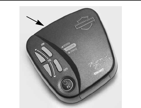
Installation
Controls and Mounting of the Road Tech Detector
Integrated
Mount

Page 8
Controls and Features
Power and Mute:
To turn the Road Tech 75 on, simply press and
hold
the large round button located on the top of the detector. To
turn Road Tech off, simply press and
hold
again.
This button also provides audio Mute capability. During an alert,
momentarily
press this button to silence the audio for that specific signal.
Once that signal has passed, the audio will return to the volume level you
selected.
Power-on Indication:
After the Road Tech 75’s start-up sequence is com-
plete, the matrix display will show “Highway”, “City”, or “Auto” to show which
sensitivity mode is selected. If you prefer, you can select alternate power-on
indications. See the EZ Programming section for details.
Volume Adjust:
To adjust the audio volume on the Road Tech 75, simply
press the
VOL
up button to increase or press the
VOL
down button to
decrease the audio level. A corresponding bar graph will be displayed to show
you where the volume is set. Your volume setting is stored in memory.
AutoMute:
Your Road Tech 75 has Escort’s patented AutoMute feature. After
it alerts you to a radar encounter at the full volume, it will automatically reduce
the volume to a lower level. This keeps you informed without the intensity of a
continuous full-volume alert. If you prefer, you can turn the AutoMute feature
off. See the EZ Programming section for details.
Highway / Auto / City Switch:
The
CITY
button selects the Road Tech 75’s
sensitivity mode. We recommend the Auto (AutoSensitivity) mode for most
riding.
Road Tech’s AutoSensitivity mode provides long-range warning, without false
alarms from automatic door openers etc. In this mode, the internal computer

Page 9
Controls and Features
continuously analyzes all incoming signals and intelligently rejects false
alarms.
You can also select Highway and City modes. When riding in urban areas
where intense X-band intrusion alarms and door openers are common, City
mode can be engaged to lower X-band sensitivity and reduce X-band alerts.
Full sensitivity is maintained on all other bands.
You can customize the City mode sensitivity. See the EZ Programming section
for details.
Dim:
The Road Tech 75’s
DIM
button selects the brightness of the display.
There are four settings: Maximum, Medium, Minimum, and Dark. Press the
DIM
button to select your preferred brightness. Each time you turn the detec-
tor on, it automatically selects the brightness setting you last used.
Dark Mode:
When you select Dark mode using the DIM switch, the display
changes to a very inconspicuous power-on indication: a very dim “AD”, “HD”,
or “CD”. (In this display, the “A,” “H” or “C” indicates Auto, Highway, or City, and
the D indicating Dark.)
When the detector is in the Dark mode, the display will not show visual alerts
when it detects signals. Only the audible alert will tell you of detected signals.
Audible Alerts:
For Radar signals: The Road Tech 75 uses a geiger-counter-
like sound to indicate the signal strength and type of radar signal being
encountered. When you encounter radar, a distinct audible alert will sound
and occur faster as the signal gets stronger. When the signal is very strong,
the audible alerts will blend into a solid tone. This allows you to judge the dis-
tance from the signal source without taking your eyes from the road.
NOTE
Since Laser and “POP” signals are a possible threat no matter how weak, the
Road Tech 75 alerts you to these with a full alert.

Page 10
Controls and Features
Signal Strength Meter:
The Road Tech 75’s matrix display consists of 280
individual LED’s, to provide an intuitive ultra-bright display of signal strength
and text messages. When the Road Tech 75 detects radar, it displays the band
of the radar (X, K, or Ka), and a precise bar graph of signal strength. When
Road Tech detects laser or POP, the display will show “LASER” or “POP”.
NOTE
If you are operating the Road Tech 75 in the Dark mode, the display will not
light when a signal is detected- only the audio will alert you.
ExpertMeter:
The Road Tech 75’s ExpertMeter option is an advanced display
for experienced detector users. Please use the detector for a few weeks to get
familiar with its other features before using ExpertMeter.
To use the ExpertMeter instead of the bar graph signal strength meter, you
must select ExpertMeter in the EZ Programming section.
See page 12.
The Road Tech 75’s standard signal strength meter only displays information
about a single radar signal. If there are multiple signals present, the Road
Tech 75’s internal computer determines which one is the most important
threat to show on the bar graph meter. However, the Road Tech 75’s Expert-
Meter simultaneously tracks up to 8 radar signals. It shows you detailed infor-
mation on up to 2 Ka-band, 2 K-band, and 4 X-band signals.
ExpertMeter can help you spot a change in your normal riding environment;
for example, a traffic radar unit being operated in an area where there are nor-
mally other signals present. The ExpertMeter is actually a miniature spectrum
analyzer. It shows what band each signal is, its relative frequency within the
band, and its signal strength.
Above is the ExpertMeter display if the Road Tech 75 was detecting 2 strong
Ka-band, 2 strong K-band, and 4 strong X-band signals.
KA K X

Page 11
Controls and Features
As you can see, there are vertical lines after each band designator. Each line
shows a signal being detected. The height of each line shows the relative sig-
nal strength of that signal. The position of the line shows the relative frequency
of the signal within the band.
NOTE
If you use ExpertMeter, the brief signal shown in the power-on sequence
when you turn on your Road Tech 75 will also be in ExpertMeter: an X with a
single vertical line.
A few more examples will help you better see how the ExpertMeter works.
Here ExpertMeter shows 1 strong K-band signal, and three X-band signals,
two strong and one weak.
Here ExpertMeter shows 1 weak Ka-band signal, and three weak X-band sig-
nals.
On very weak signals, there will not be a vertical line at all. This shows a very
weak X-band signal.
ExpertMeter Details:
The band designators (X, K, and Ka) will stay on the
display for a few seconds after the signal has passed. This allows you to see
what the unit detected, even on very brief signals. However, the vertical lines
representing individual signals continuously change (several times a second)
to give you a continuous and instantaneous view of all radar signals present.
NOTE
Even long-time detector users will require a significant time to get familiar with
this new level of information about detected signals.
K X
KA X
X

Page 12
Customize Road Tech with EZ Programming
There are 8 user-selectable options so you can customize your Road Tech 75
for your own preferences. The CITY and DIM buttons are used to enter the
Program mode, to review your current program settings, and to change any
settings as desired. “Details of EZ Programming Options” on page 16 will
explain each option in more detail.
How to use EZ Programming
1. To enter Program mode, hold both the
CITY
and
DIM
buttons down for 2
seconds. (The unit will beep twice, and will display “Program”).
2. Then press the
REVIEW
button to review the current settings. (You can
either tap the button to change from item to item, or hold the button to
scroll through the items.)
3. Press the
CHANGE
button to change any setting. (You can either tap
the button to change from setting to setting, or hold the button to scroll
through all the options.)
4. To leave the Program mode, simply wait 8 seconds without pressing any
button. (The unit will display “Complete”, beep 4 times, and return to nor-
mal operation.)
(To quickly return to the all of the factory defaults, hold the
CITY
,
DIM
buttons
down while turning on the unit.)

Page 13
Customize Road Tech with EZ Programming
Example of Programming
Here is how you would turn the Road Tech 75’s AutoMute feature off.
1. Enter the Program mode by holding the
CITY
and
DIM
buttons down for
2 seconds. The Road Tech 75 will beep twice and display “Program”.
2. Then hold the
REVIEW
button down. The Road Tech 75 will scroll
through the categories, starting with Pilot Light (“Pilot”), then Power
(“Pwr Auto”), then Power-On Sequence (“PwrOn”), then Signal Strength
Meter (“Meter”), and then AutoMute (“aMute”).
3. Release the
REVIEW
button when the Road Tech 75 shows the Auto-
Mute item. Since the factory setting is for AutoMute to be on, the Road
Tech 75 will display “aMute ON”. (If you accidentally don’t release the
Review
button in time, and the Road Tech 75 goes to the next category,
simply continue to hold the
Review
button down until it scrolls through
all categories. It will begin again at the top of the list.)
4. Press the
CHANGE
button to change from aMute ON to aMute OFF.
5. To complete the Programming, simply wait 8 seconds without pressing
any button. The Road Tech 75 will display “Complete”, beep 4 times, and
return to normal operation.

Page 14
Customize Road Tech with EZ Programming
Overview of EZ Programming Options
Press the
REVIEW
button to
go from one category to the
next
Press the
CHANGE
button to change your set-
ting within a category
PILOT LIGHT
(Power-on indication) Pilot HWY * (full word: Highway or Auto or City)
Pilot H (letter: H or Auto or C)
Pilot H.> (letter, with scanning dot)
Pilot V (motorcycle voltage)
POWER -UP
Pwr Auto *(power on with the Motorcycle)
Pwr Man (power on manually)
POWER-ON SEQUENCE
PwrOn STD *(standard power-on sequence)
PwrOn FST (fast power-on sequence)
SIGNAL STRENGTH
METER
Meter STD * (standard bar-graph)
Meter EXP (Expert Meter)
AUTOMUTE
aMute ON * (automute on)
aMute OFF (automute off)
CITY MODE SENSITIVITY
City STD * (Standard City mode sensitivity)
City LoX (low X-band sensitivity in City mode)
City NoX (No X band sensitivity in City mode)
DARK MODE
Dark STD (provides dim HD, AD, or CD)
Dark ALL (All dark, no visual indications)

Page 15
Customize Road Tech with EZ Programming
BANDS
Bands DFT (Factory defaults)
Bands MOD (Factory defaults modified)
(turn bands on or off by pressing the
Power
/
Mute
button)
X On or Off (default is on)
K On or Off (default is on)
Ka On or Off (default is on)
POP On or Off (default is off)
Laser On or Off (default is on)
SWS On or Off (default is off)
VG2 On or Off (default is off)
*These are Road Tech 75’s factory settings
Overview of EZ Programming Options

Page 16
Customize Road Tech with EZ Programming
Details of EZ Programming Options
Pilot Light (power-on indication): NOTE
When you are using the Dark mode, the display will only show “HD”, “AD”, or
“CD,” (Highway-Dark, Auto-Dark, or City-Dark).
Pilot HWY (full description)
In this setting, Road Tech 75 will display “Highway,” “City,” or “Auto” as its
power-on indication. (factory default)
Pilot H (letter)
In this setting, Road Tech 75 will display “H” for Highway, “C” for City, and “A”
for Auto.
Pilot H.> (Letter with scanning dot)
In this setting, Road Tech 75 will display “H” for Highway, “C” for City, and “A”
for Auto. Also, a single dot will continuously scroll across the display.
Pilot V (motorcycle voltage)
In this setting, Road Tech 75 will continually display “H” for Highway, “C” for
City, and “A” for Auto, and the motorcycle voltage. If the motorcycle voltage
drops below 9.0 volts, a low voltage warning is displayed, followed by an audi-
ble alert. A high voltage warning is also given if the voltage goes above
15.0 volts.
Power-Up:
PwrAuto (standard)
In this setting, Road Tech 75 will turn on or off automatically with the bike’s
ignition.
PwrMan (manually)
In this setting, Road Tech 75 will need to be turned on with the top-mounted
Power/Mute
button.

Page 17
Customize Road Tech with EZ Programming
Power-On Sequence:
PwrOnSTD (standard)
In this setting, each time the Road Tech 75 comes on, it will display “Road
Tech”, “75”, “LASER”, “Ka-band”, “K-band”, “X-band”, followed by a brief X-
band alert. (factory default)
PwrOnFST (fast power-on)
In this setting, each time you turn on Road Tech 75, it will display a brief X-
band alert.
Signal Strength Meter:
MeterSTD (standard meter)
In this setting, the meter displays the band of the received signal, and a bar
graph showing the relative signal strength. (factory default)
MeterEXP (Expert Meter)
In this setting, the meter simultaneously tracks multiple radar signals. It shows
up to 2 Ka band, 2 K band, and 4 X band signals.
NOTE
The ExpertMeter feature is explained in more detail on page 10.
AutoMute:
aMute ON (automute on)
In this setting, the Road Tech 75’s audio alerts will initially be at the volume
you’ve set, but after a few seconds, the audio will automatically reduce the
volume level, to keep you informed, but at a lower volume. (factory default)
aMuteOFF (automute off)
With AutoMute off, Road Tech 75’s audio alerts will remain at the volume you
set for the duration of the radar encounter.
Details of EZ Programming Options

Page 18
Customize Road Tech with EZ Programming
City Mode Sensitivity:
City STD (Standard)
In this setting, when you put the Road Tech 75 in the City mode, X-band sen-
sitivity is significantly reduced, to reduce false alarms from X-band intrusion
alarms and motion sensors. (factory default)
City LoX (Low X band sensitivity)
In this setting, when you put Road Tech 75 in the City mode, X-band sensitiv-
ity is reduced more than the standard setting. This will reduce X band alarms
from other sources even further, but also significantly reduces range to X
band traffic radar.
City NoX (No X band sensitivity)
In this setting, when you put Road Tech 75 in the City mode, Road Tech will
not respond to any X band signals.
NOTE
Only choose this setting if you are absolutely certain that there are no X band
traffic radar units where you ride.
Dark Mode:
Dark STD (standard)
In this setting, when you select dark mode in programming, the only visual
indication will be a very dim HD, AD, or CD, indicating the sensitivity setting
and that the detector is in the dark mode. (Highway-Dark, Auto-Dark, or City-
Dark) (factory default)
Dark ALL (completely dark)
In this setting, when you select dark mode in programming, the Road Tech 75
will become totally dark. This means that there will be no alert lamp or display
indication. However, during start-up, a brief “Dark All” message will appear,
notifying the user that the detector is in this mode.
Details of EZ Programming Options

Page 19
Customize Road Tech with EZ Programming
Bands:
BandsDFT
In this setting the recommended radar and laser frequencies are monitored.
This is the factory setting, and it is recommended that you use your Road
Tech 75 in this mode.
BandsMOD
In this setting, the Road Tech 75 will warn you with an audible alert, and asso-
ciated text message stating which band has changed from the original factory
setting (i.e. “POP ON”). This warning is displayed during the start up
sequence (standard or fast).
NOTE
Do not turn off a band unless you are absolutely certain that there are no
traffic radar units using that specific band in your area.
Details of EZ Programming Options

Page 20
Interpreting Alerts
Although the Road Tech 75 has a comprehensive warning system and this
handbook is as complete as we can make it, only experience will teach you
what to expect from your Road Tech 75 detector and how to interpret what it is
telling you. The radar alerts you receive are affected by the specific type of
radar being used, the type of transmission (continuous or instant-on) and the
location of the radar source.
The following examples will give you an introduction to understanding the
Road Tech 75’s warning system for radar, laser and safety alerts.
Alert Explanation
Road Tech 75 begins to sound slowly,
and then the rate of alerts increases
until the alert becomes a solid tone.
The Signal Meter ramps accordingly.
You are approaching a continuous
radar source aimed in your direction.
Road Tech 75 emits short alerts for a
few seconds and then falls silent only
to briefly alert and fall silent again.
An instant-on radar source is being
used ahead of you and out of your
view.
Road Tech 75 suddenly sounds a con-
tinuous tone for the appropriate band
received. All segments in the Signal
Strength Meter are lit.
An instant-on radar source or laser
source is being used nearby. This kind
of alert requires immediate attention!
A brief laser alert. Laser is being used in the area.
Because laser is inherently difficult to
detect, any laser alert may indicate a
source very close by.

Page 21
Interpreting Alerts
Road Tech 75 receives weak signals.
These signals may be a little stronger
as you pass large, roadside objects.
The signals increase in frequency.
A moving patrol car with continuous
radar is overtaking you from behind.
Because these signals are reflected
(reflections are increased by large
objects), they may or may not eventu-
ally melt into a solid point even when
the patrol car is directly behind you.
Road Tech 75 alerts slowly for awhile
and then abruptly jumps to a strong
alert.
You are approaching a radar unit con-
cealed by a hill or an obstructed curve.
Road Tech 75 alerts intermittently.
Rate and strength of alerts may be
consistent or vary wildly.
A patrol car is traveling in front of you
with a radar source aimed forward.
Road Tech 75 alerts intermittently. Because signals are sometimes
reflected off of large objects and
sometimes not, the alerts may seem
inconsistent.
A patrol car is approaching from the
other direction, sampling traffic with
instant-on radar. Such alerts should
be taken seriously.
Alert Explanation

Page 22
Interpreting Alerts
CAUTION
Since the characteristics of these alerts may be similar to some of the
preceding examples, overconfidence in an unfamiliar area can be
dangerous. Likewise, if an alert in a commonly traveled area is suddenly
stronger or on a different band than usual, speed radar may be set up
nearby.
Road Tech 75 gives an X-band alert
intermittently. You are riding through an area popu-
lated with radar motion sensors (door
openers, burglar alarms, etc.) Since
these transmitters are usually con-
tained inside buildings or aimed
toward OR away from you, they are
typically not as strong or lasting as a
real radar encounter.
Alert Explanation

Page 23
Detection Technology
How Radar Works
Traffic radar, which consists of microwaves, travels in straight lines and is eas-
ily reflected by objects such as cars, trucks, even guardrails and overpasses.
Radar works by directing its microwave beam down the road. As your motor-
cycle travels into range, the microwave beam bounces off your motorcycle,
and the radar antenna looks for the reflections. Using the Doppler Principle,
the radar equipment then calculates your speed by comparing the frequency
of the reflection of your motorcycle to the original frequency of the beam sent
out.
Traffic radar has limitations, the most significant of these being that it typically
can monitor only one target at a time. If there is more than one car or motorcy-
cle within range, it is up to the radar operator to decide which target is produc-
ing the strongest reflection. Since the strength of the reflection is affected by
both the size of the car or motorcycle and its proximity to the antenna, it is dif-
ficult for the radar operator to determine if the signal is from a car or motorcy-
cle nearby or a semi-truck several hundred feet away.
Radar range also depends on the power of the radar equipment itself. The
strength of the radar unit’s beam diminishes with distance. The farther the
radar has to travel, the less energy it has for speed detection.
Because intrusion alarms and motion sensors often operate on the same fre-
quency as X-band and K-band radar, your Road Tech 75 will occasionally
receive non-police radar signals. Since these X-band and K-band transmitters
are usually contained inside of buildings or aimed toward the ground, they will
generally produce much weaker readings than will a true radar encounter.
As you become familiar with the sources of these pseudo alarms in your daily
riding, they will serve as confirmation that your Road Tech 75’s radar detection
abilities are fully operational.

Page 24
Detection Technology
How POP Works
POP mode is a relatively new feature for radar gun manufacturers. It works by
transmitting an extremely short burst, within the allocated band, to identify
speeding vehicles and motorcycles in traffic. Once the target is identified, or
“Popped”, the gun is then turned to its normal operating mode to provide a
vehicle tracking history, which is required by law.
How Laser Works
Laser speed detection is actually LIDAR (Light Detection and Ranging).
LIDAR guns project a beam of invisible infrared light. The signal is a series of
very short infrared light energy pulses which move in a straight line, reflecting
off your motorcycle and returning to the gun.
LIDAR uses these light pulses to measure the distance to a motorcycle.
Speed is then calculated by measuring how quickly these pulses are reflected
given the known speed of light. LIDAR (or laser) is a newer technology and is
not as widespread as conventional radar, therefore, you may not encounter
laser on a daily basis. And unlike radar detection, laser detection is not prone
to false alarms. Because LIDAR transmits a much narrower beam than does
radar, it is much more accurate in its ability to distinguish between targets and
is also more difficult to detect. AS A RESULT, EVEN THE BRIEFEST LASER
ALERT SHOULD BE TAKEN SERIOUSLY.
There are limitations to LIDAR equipment. LIDAR is much more sensitive to
weather conditions than RADAR, and a LIDAR gun’s range will be decreased
by anything affecting visibility such as rain, fog, or smoke.
A LIDAR gun cannot operate through glass and it must be stationary in order
to get an accurate reading. Because LIDAR must have a clear line of sight and
is subject to cosine error (an inaccuracy which increases as the angle
between the gun and the motorcycle increases) police typically use LIDAR
equipment parallel to the road or from an overpass. LIDAR can be used day or
night.

Page 25
Detection Technology
How Safety Radar Works
From the factory, your Road Tech 75 is programmed with Safety Warning Sys-
tem (SWS) decoding OFF. If SWS is used in your area, your Road Tech 75 will
display these signals as K-band radar signals instead of safety radar unless
you use the EZ Programming to turn Road Tech 75’s SWS decoding ON.
The SWS safety radar system has 64 possible messages (60 currently allo-
cated). The SWS messages displayed on your Road Tech are listed below.
NOTE
Some of the safety messages have been condensed, so each message can
be displayed on one or two screens on Road Tech 75’s eight character display.
Since SWS is relatively new and the number of transmitters in operation is not
yet widespread, you will not receive SWS alerts on a daily basis and should
not be surprised to encounter emergency vehicles, road hazards and railroad
crossings that are unequipped with these transmitters and, therefore, fail to
provide a signal.

Page 26
SWS Safety Radar Text Messages
1 WorkZone 23 Deer Crossing 45 24hrFuel
2 Road Closed 24 Blind or Deaf Kid 46 Insp Stn Open
3 Bridge Closed 25 SteepUse LowGear 47 Insp Stn Open
4 WorkCrew Highway 26 Accident 48 Reduced Speed
5 WorkCrew Utility 27 PoorRoad Surface 49 Speed Enforced
6 Detour 28 Loading SchooBus 50 HazMatls Exit
7 Truck Detour 29 DontPass 51 Expect Delay
8 MustExit 30 Dangrous Intrsect 52 10 Min Delay
9 Rtlane Closed 31 Emergncy Vehicle 53 20 Min Delay
10 CntrLane Closed 32 Future use 54 30 Min Delay
11 LeftLane Closed 33 HighWind 55 1 Hour Delay
12 Future use 34 Severe Weather 56 Traffic TunRadio
13 Police 35 HeavyFog 57 Pay Toll
14 Train 36 Flooding 58 Trucks ExitRght
15 Low Overpass 37 BridgIce 59 Trucks ExitLeft
16 BridgeUp 38 RoadIce 60 Future use
17 Bridge Wt Limit 39 Dust Blowing 61 EmergVeh Moving
18 RockSlid Area 40 Sand Blowing 62 Police Pursuit
19 School Zone 41 Blinding Snow 64 Oversize Vehicle
20 Road Narrows 42 Future use 65 SloMovng Vehicle
21 Sharp Curve 43 RestArea
22 Croswalk 44 RestArea w/service

Page 27
Troubleshooting
Problem Solution
Road Tech 75 beeps briefly at the
same location every day, but no radar
source is in sight.
An X-band motion sensor or intrusion
alarm is located within range of your
route. With time, you will learn predict-
able patterns of these signals.
Road Tech 75 does not seem sensi-
tive to radar Road Tech 75 may be in City mode.
Road Tech 75 did not alert when a
police car was in view. VASCAR, (Visual Average Speed
Computer and Recorder) a stopwatch
method of speed detection, may be in
use or the officer may not have radar
or laser unit turned on.
Road Tech 75 did not provide a Safety
signal while within range of an emer-
gency vehicle.
Safety transmitters may not be com-
monly used in your area.
Road Tech 75’s display is not working. Press the DIM button to deactivate
Dark mode.
Road Tech 75’s audible alerts are less
loud after the first few alerts. Road Tech 75 is in AutoMute mode.
See page 17.
Road Tech 75’s power-on sequence
reoccurs while you are riding. Road Tech 75 may not be fully
engaged to the mount. Check connec-
tion or contact your dealer.
Your 14-year old son has changed all
8 of the EZ programming options. You can return all of the programming
options to the factory defaults by hold-
ing down the CITY and DIM buttons
while you turn Road Tech 75 on.

Page 28
Explanation of Displays
AD Sensitivity control is in Auto mode, display in Dark mode
HD Sensitivity control is in Highway mode, display in Dark
mode
CD Sensitivity control is in City mode, display in Dark mode
No Display Road Tech 75 is in Dark mode
PilotHWY One of the many programming messages
WorkZone One of the many safety radar messages.
Caution Road Tech 75 has detected a Safety Radar Signal, but
the signal isn’t strong enough to decode the specific
safety message.
X|, or K|, or Ka
or KA| etc. Road Tech 75 has been programmed in the ExpertMeter
mode

Page 29
Service
The ROAD TECH 75 DETECTOR has no serviceable parts. If problems arise,
check the troubleshooting section in this manual for a solution. If a solution is
not available in the troubleshooting section, please contact your local dealer.
They will evaluate your detector and mount and arrange repairs if necessary.

Page 30
Care and Maintenance
The case of your Harley-Davidson Road Tech 75 DETECTOR is constructed
from an injection molded plastic with an LEXAN® LCD screen. Some steps will
help aid long-term reliability and cosmetic appearance.
Do not use solvent based chemicals or waxes directly on plastic components
as they can affect the overall performance and appearance of the plastic.
The black plastic front face can be cared for with a plastic/rubber protectant to
reduce the cosmetic affects of long term outdoor exposure. Follow directions
on product labels for correct application and use. Use use soft cloths such as
Harley-Davidson Microfiber Detailing Cloth (Part No. 94663-02) or Softcloth
(Part No. 94656-98) to avoid scratches.
The LEXAN screen can be cleaned with Novus® No. 1 Cleaner and Protectant
(Part No. 99837-94T).
If corrosion is present on contacts or mating spring terminals, gently wipe con-
tacts with a clean soft cloth using mild soap and water. If detector is to remain
on motorcycle for an extended period of time, a light application of dielectric
grease can be applied to the contacts to further enhance weather protection.

Page 31
Specifications
Features and Specifications
Operating Bands
X-band 10.525 GHz ± 25 MHz
K-band 24.150 GHz ± 100 MHz
Ka-band 34.700 GHz ± 1300 MHz
Laser 900nm, 33 MHz bandwidth
Radar Receiver / Detector Type
Superheterodyne, GaAs FET VCO
Scanning Frequency Discriminator
Digital Signal Processing (DSP)
Laser Detection
Quantum Limited Video Receiver
Multiple Laser Sensor Diodes
Display Type
280 LED Text/Matrix
Bar Graph or ExpertMeter™
3-Level Dimming, plus Dark mode
Power Requirement
12VDC, Negative Ground Sensitivity Control
AutoSensitivity™, Highway, and City
Programmable Features
Pilot, Power-Up, Power-On Sequence,
Signal Strength Meter, AutoMute, City
Mode Sensitivity, Dark Mode, Bands
Dimensions
4.06 x 4.08 x 1.35 inches
Patented Technology
Passport is covered by one or more of the following Escort U.S. patents:
6,693,578 6,614,385 6,587,068 6,400,305 6,249,218 6,069,580 5,668,554
5,600,132 5,559,508 5,587,916 5,446,923 5,402,087 5,365,055 5,347,120
5,305,007 5,206,500 5,164,729 5,134,406 5,111,207 5,079,553 5,049,885
5,049,884 4,961,074 4,954,828 4,952,937 4,952,936 4,939,521 4,896,855
4,887,753 4,862,175 4,750,215 4,686,499 4,631,542 4,630,054 4,625,210
4,613,989 4,604,529 4,583,057 4,581,769 4,571,593 4,313,216 D314,178
D313,365 D310,167 D308,837 D296,771 D288,418 D253,752

Page 32
Warranty and Accessories
ESCORT Limited Warranty
ESCORT and Harley-Davidson warrants your Road Tech 75 against defects in
materials and workmanship for a period of two (2) years if purchased with a
new motorcycle and installed by an authorized Harley-Davidson dealer, one
(1) year if installed by an authorized Harley-Davidson dealer, and ninety (90)
days if purchased but not installed by an authorized Harley-Davidson dealer,
and registered from the date of the original purchase, subject to the following
terms and conditions:
The sole responsibility of ESCORT and Harley-Davidson under this Warranty
is limited to either repair or, at the option of ESCORT or Harley-Davidson,
replacement of the Road Tech 75 detector. There are no expressed or implied
warranties, including those of fitness for a particular purpose or merchantabil-
ity, which extend beyond the face hereof. Some states do not allow limitations
on how long an implied warranty lasts, so the above limitations may not apply
to you.
ESCORT and or Harley-Davison are not liable for any incidental or conse-
quential damages arising from the use, misuse, or mounting of the Road Tech
75. Some states do not allow the exclusion or limitation of incidental or conse-
quential damages, so the above limitation or exclusion may not apply to you.
This Warranty gives you specific rights.
You may have other legal rights which vary from state to state. This Warranty
does not apply if the serial number on the housing of the Road Tech 75 has
been removed, or if your Road Tech 75 has been subjected to physical abuse,
improper installation, or modification.
Accessories - See all of our products and accessories at www.harley-david-
son.com
(BACK COVER)
©2004 Escort Inc. Escort®, Passport, AutoMute®, AFR®, SmartShield®,
AutoSensitivity™ and ExpertMeter™ are trademarks of Escort Inc. SWS is a
trademark of SWSLC.
Features, specifications and prices are subject to change without notice.