Escort 432 Users Manual SmartSite Mini Owners Manual*
Escort-Escort-Smartsite-Mini-Owners-Manual escort-escort-smartsite-mini-owners-manual
432 to the manual d1dc6094-5e02-41fd-b1bf-4161fc535fd0
2015-02-02
: Escort Escort-432-Users-Manual-426738 escort-432-users-manual-426738 escort pdf
Open the PDF directly: View PDF ![]() .
.
Page Count: 2
432
Features and Monitor Controls
Monitor
Specifically designed for passenger cars, trucks and SUVs.
• Supports single camera input.
• High-low voltage and short-circuit protection.
• Suction cup bracket installation.
• Automatically displays reverse camera view when reverse gear
is engaged.
Camera
• CMOS camera in mini size.
• Three-color proximity guide.
• Operates over a wide temperature range.
Owner’s Manual
R E A R V I E W C A M E R A S Y S T E M
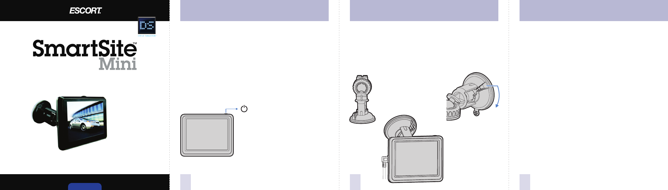
Monitor Installation
• Install the monitor on the windshield of the car.
• Don’t install the monitor in an extremely hot or humid place
(radiator, air duct, etc.) or in a place subject to direct sunlight,
excessive dust, mechanical vibration or shock.
• The monitor is not waterproof.
Attach the supplied bracket to the glass or flat area and make
sure it’s firmly affixed.
System power ON/OFF
Camera Installation
Adjust the angle of
the monitor and
fasten the back
screw firmly.
First, find the
best position
and angle. Second, rotate
the bracket and
fix it firmly.
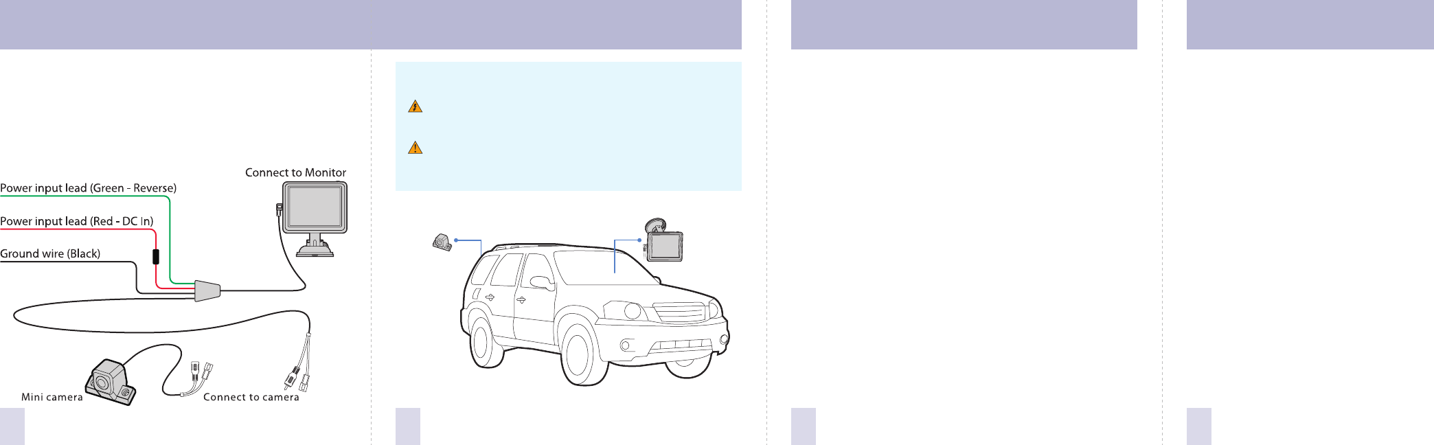
• Use a silicon waterproof tape to wrap the connector of camera
and extension cable to ensure waterproof.
• Protect the cable by using conduit or running the cable inside the
vehicle as much as possible.
Cleaning and General Maintenance Connection Specifications and Service
SPECIFICATIONS
Monitor
LCD profile widescreen ratio .............................................................4:3
Wide view angle (CR) ..........20/50 (up/down), 40/40 (left/right)
Resolution ........................................................................230x400 pixels
Brightness (cd/m2) ............................................................................... 250
Contrast ratio .......................................................................................... 300
Response time (ms) (at 25°C) ...............................................................20
Power requirement ........... 12VDC, with control box (12/24VDC)
Power consumption ........................................................................... ≤2W
Operating temperature range ................................... -20°C to +70°C
Storage temperature range ........................................-30°C to +80°C
Dimensions (mm) ............................................. 95 (L) x 75 (W) x 16 (D)
Weight (approx.) (gm) ............................................................................80
SERVICE
To obtain service: Contact ESCORT (800-543-1608) to obtain a Return Authorization
Number. Properly pack your product and include: your name, complete return address,
written description of the problem with your product, daytime telephone number,
and a copy of the original purchase receipt. Label the outside of the package clearly
with your Return Authorization number. Ship the product prepaid (insured for your
protection) to: ESCORT Inc., 5440 West Chester Road, West Chester, OH 45069.
Out-of-warranty repairs:
For out-of-warranty repairs, include prepayment in the amount you were quoted by
the ESCORT Customer Service Representative. If your SmartSite Mini has been
damaged, abused, or modified, the repair cost will be calculated on a parts-and-labor
basis. If it exceeds the basic repair charge, you will be contacted with an estimate. If the
additional payment is not received within 30 days (or if you notify us that you do not
wish to have your SmartSite Mini repaired at the price quoted), the unit will be
returned without repair. Payment can be made by check, money order, or credit card.
ESCORT Inc.
5440 West Chester Road 800.433.3487
West Chester OH 45069 www.EscortInc.com
©2012 ESCORT Inc. ESCORT® and SmartSite™ Mini are trademarks of ESCORT Inc.
Features, specifications and prices subject to change without notice.
8765
Wiring Diagram
• Connect the RED wire to the 12V or 24V DC power terminal which
is energized with the ignition key in the accessory position.
• Connect the BLACK wire to a suitable negative connection point
on the vehicle.
• Connect the GREEN wire to the switched power output terminal
of the “R” (reverse) gear. Trigger is always in priority.
CAUTION:
Before making connections, disconnect the ground
terminal of the car battery to avoid a short circuit.
The plugs should be fully inserted into the connectors or
jacks. A loose connection may cause malfunctioning of the
unit.
If your vehicle has been parked in direct sun light resulting in a
considerable rise in temperature inside the vehicle, allow the unit to
cool off before operating. Clean the unit with a slightly damp soft
cloth. Use a mild household detergent. Never use strong solvents
such as thinner or benzine as they might damage the finish of the
unit.
Cleaning
Unplug or power off before cleaning. Do not use liquid cleaners or
aerosol cleaners. Use a damp cloth for cleaning.
Ventilation
Holes in the housing and the back or bottom are provided for
ventilation, and to ensure reliable operation of the monitor
equipment for protection from overheating. These holes must not
be blocked or covered.
Object and Liquid Entry
Never push objects of any kind into the monitor equipment through
holes as they may touch dangerous voltage points or short-out
parts that could result in a fire or electric shock. Never spill liquid of
any kind.
Servicing
Do not attempt to service this system by yourself as opening or
removing covers may expose you to dangerous voltage or other
hazards. Refer all servicing to qualified service personnel.
