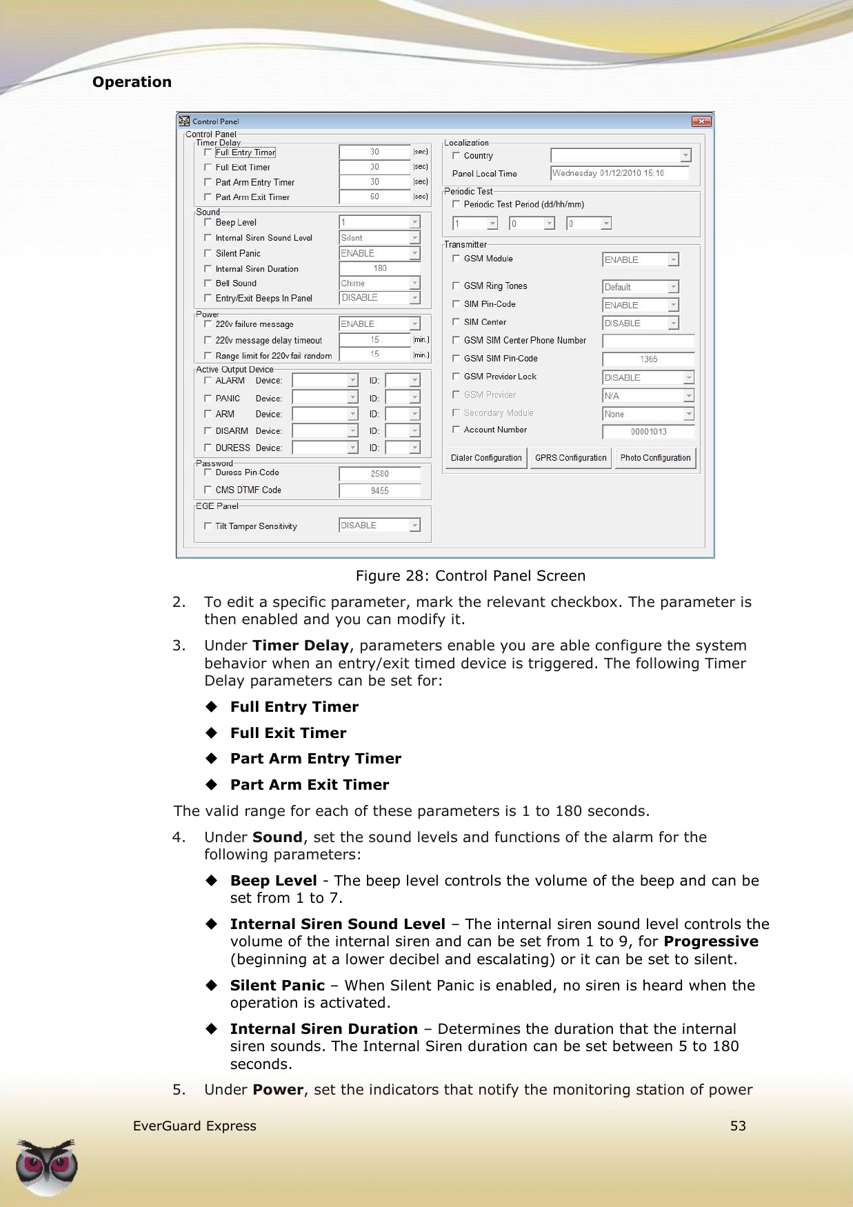
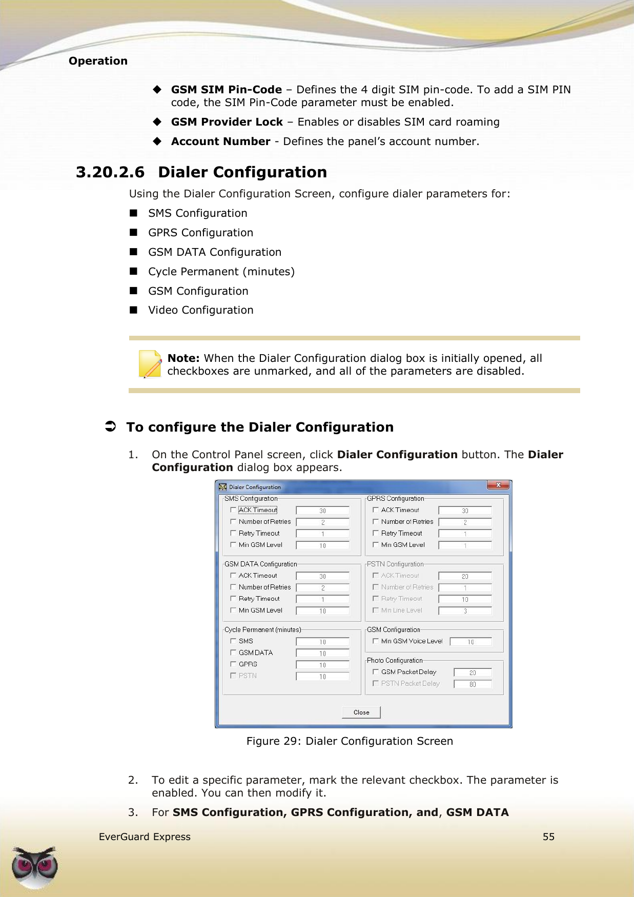
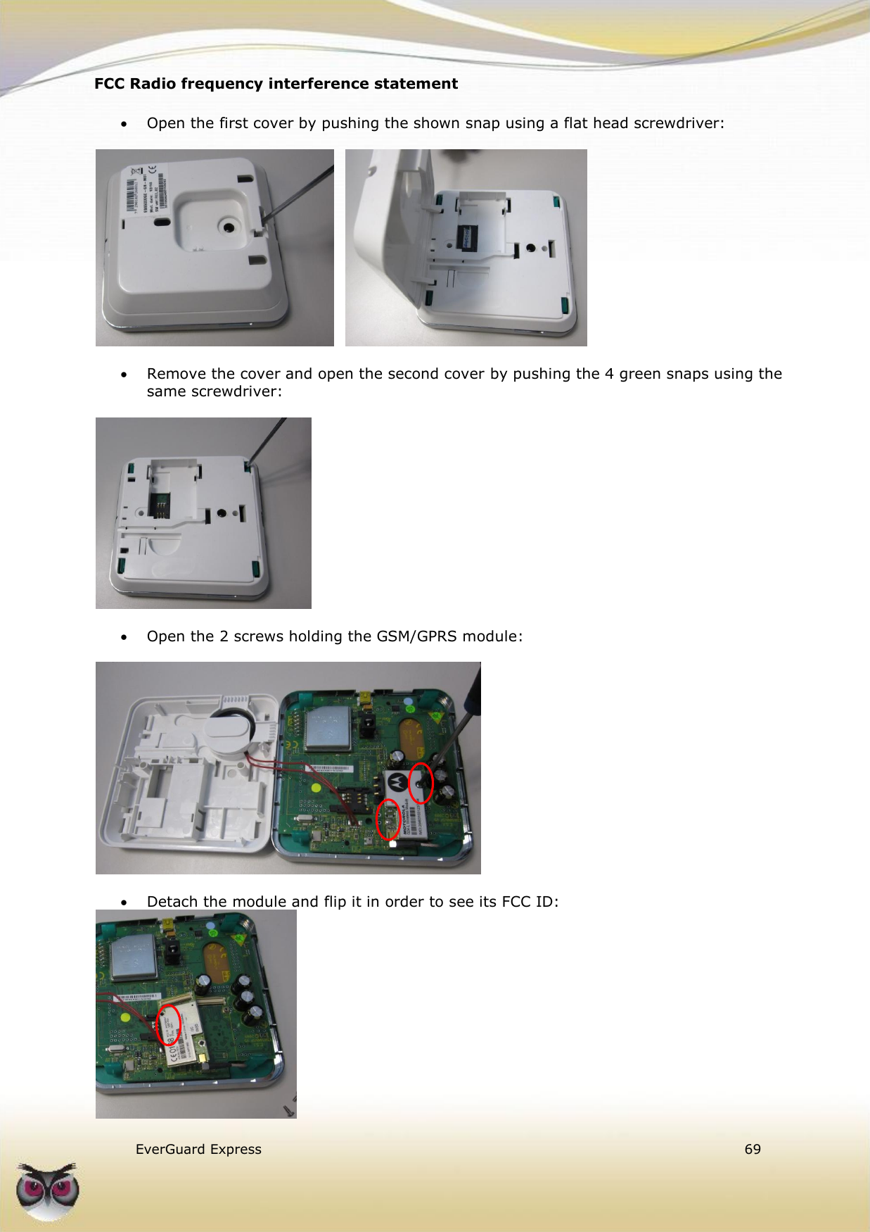
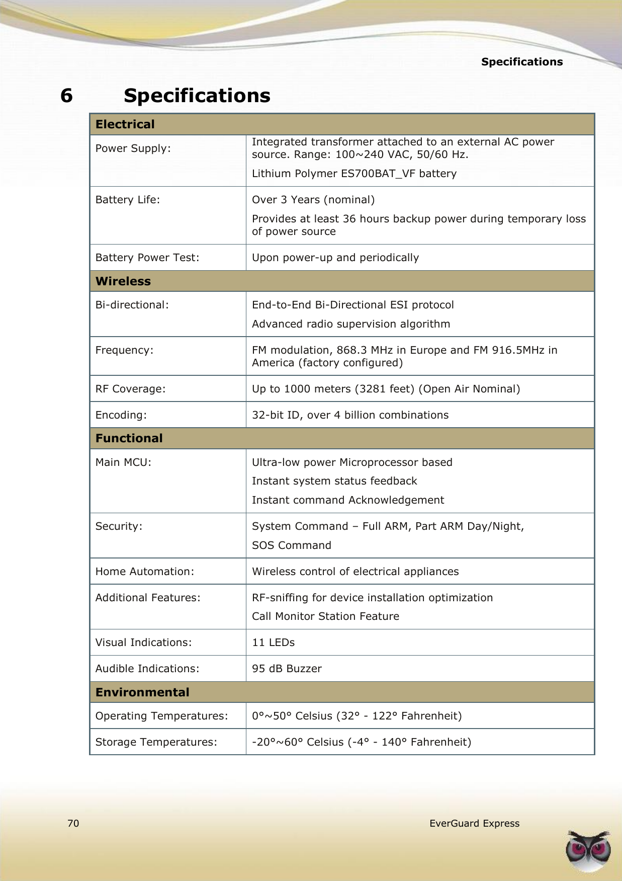
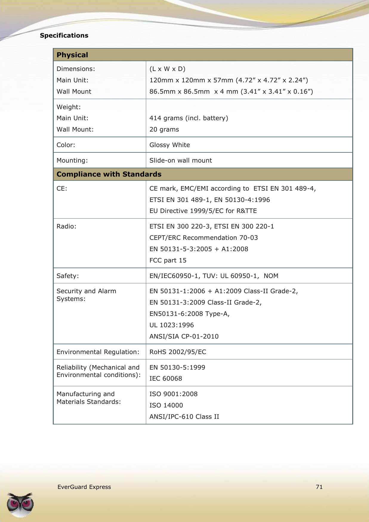
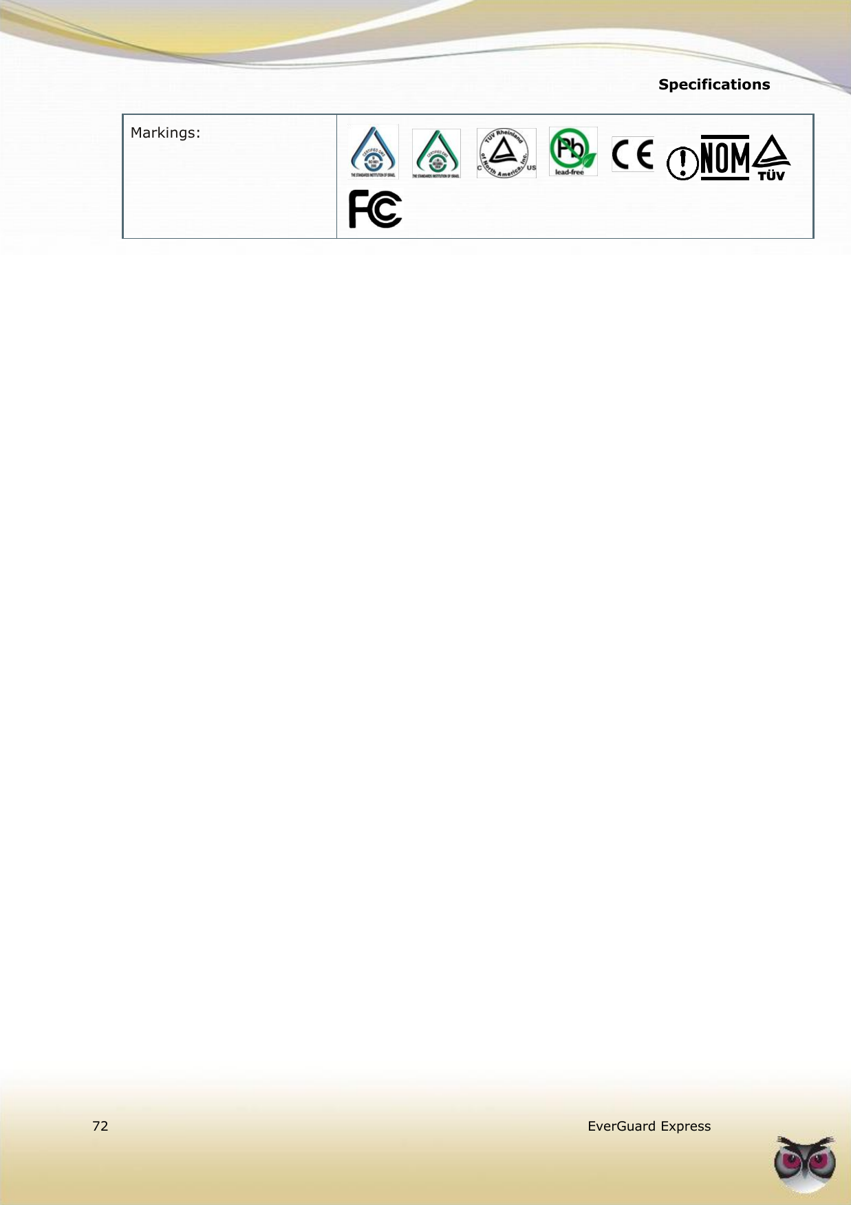
Essence Security ES6500EGE Alarm system control panel User Manual EverGuard Express

Essence Security International ltd. Alarm system control panel EverGuard Express

User Manual

       EESS66550000EEGGEE  VVeerrssiioonn  55..11  JJaannuuaarryy  22001111  EEvveerrGGuuaarrdd  EExxpprreessss  CCoonnttrrooll  PPaanneell    UUsseerr  GGuuiiddee
            © 2011 EGI Group Ltd. (Essence Global Innovations Group Ltd.) All rights reserved. This document is the protected intellectual property of the Essence group. Any copying, reprinting, reuse, reproduction ,adaptation distribution or translation without the prior written permission of EGI Group is prohibited.  The information included in this document is subject to change without notice.  For more information, please contact:  EGI Group Ltd. 11 Galgalei HaPlada Street. Herzliya Pituach 46120 Israel www.essence-grp.com Tel:         +972-73-2447777 Fax:        +972-9-9564182
Table of Contents     EverGuard Express  3  Table of Contents 1 Overview ............................................................................................. 6 2 Installation .......................................................................................... 7 2.1 Power ....................................................................................................... 7 2.1.1 Power Status ................................................................................. 7 2.2 Inserting the Battery and SIM Card .............................................................. 7 2.3 EverGuard Express Wall Mount ..................................................................... 9 2.4 Connecting the Mini USB Cable .................................................................. 10 3 Operation .......................................................................................... 11 3.1 About the EverGuard Express Control Panel Equipment ................................. 11 3.2 Audible Indicators .................................................................................... 13 3.3 Wireless Communication Status ................................................................. 14 3.4 System Status ......................................................................................... 14 3.5 Programming the EverGuard Express Panel ................................................. 15 3.5.1 Accessing Programming Mode ........................................................ 15 3.5.2 Audible Indicators during Configuration ........................................... 17 3.6 Defining Users ......................................................................................... 17 3.7 Defining Peripherals .................................................................................. 18 3.8 Setting Exit/Entry Times............................................................................ 18 3.9 Setting Entry/Exit Countdown Beeps ........................................................... 19 3.10 Defining the Telephone Numbers for Incoming Calls ..................................... 19 3.11 Defining Telephone Numbers for Outgoing Calls ........................................... 20 3.12 Programming the Arm Function .................................................................. 21 3.13 Setting Operational Status ......................................................................... 21 3.13.1 Transmitting the EverGuard Express Configuration to the Monitoring Station  22 3.13.2 Switching from ITS to CCS Mode .................................................... 22 3.13.3 Returning the EverGuard Express Panel to Factory Default Settings .... 22 3.14 Arming and Disarming the System ............................................................. 22 3.14.1 The Arm Cycle .............................................................................. 23 3.14.2 Arm Status .................................................................................. 24 3.14.3 Arming the EverGuard Express System ........................................... 24 3.14.4 Disarming the System ................................................................... 24 3.15 Handling the Alarm ................................................................................... 25 3.15.1 Alarm Status ................................................................................ 25 3.16 Using Home Automation ............................................................................ 26
  4   EverGuard Express  3.16.1 Activating the “Comfort Camera” request ........................................ 26 3.16.2 Comfort Camera status ................................................................. 26 3.16.3 Activating the Door Lock ................................................................ 27 3.16.4 Door Lock Activation Status ........................................................... 27 3.17 Calls ....................................................................................................... 27 3.17.1 Call Status ................................................................................... 28 3.17.2 Adjusting the Call Volume .............................................................. 29 3.17.3 Calling Emergency ........................................................................ 29 3.17.4 Emergency Number Status ............................................................ 29 3.17.5 Monitoring Station Communication ................................................. 30 3.17.6 Monitoring Station Status .............................................................. 30 3.17.7 Sending an SOS Message .............................................................. 31 3.17.8 SOS Status .................................................................................. 31 3.18 Making a Telephone Call ............................................................................ 31 3.19 Receiving a Telephone Call ........................................................................ 32 3.20 Optional Settings and Defaults ................................................................... 32 3.20.1 Atlas Mobile Application ................................................................. 32 3.20.1.1 Configuring System and Photo Scenarios ........................... 33 3.20.1.2 Configuring the Control Panel ........................................... 35 3.20.1.3 Configuring the Dialer Settings ......................................... 36 3.20.1.4 Configuring the Operation Code ........................................ 38 3.20.1.5 Configuring the Account Info ............................................ 39 3.20.1.6 Configuring the User Settings ........................................... 41 3.20.2 ESI-CMS Application ..................................................................... 44 3.20.2.1 Connecting to the Control Panel ........................................ 44 3.20.2.2 Accessing ES6500EGE Panel Information ........................... 45 3.20.2.3 EverGuard Express Main Interface .................................... 47 3.20.2.4 System Parameters ......................................................... 51 3.20.2.5 Control Panel ................................................................. 52 3.20.2.6 Dialer Configuration ........................................................ 55 3.20.2.7 GPRS Configuration ......................................................... 56 3.20.2.8 Photo Configuration ........................................................ 57 3.20.2.9 Dialer ............................................................................ 60 3.20.2.10 User Settings ................................................................. 61 3.20.2.11 Custom Labels ................................................................ 63 3.20.2.12 Incoming Phone Numbers ................................................ 64 3.20.2.13 Outgoing Phone Numbers ................................................ 65 4 Maintenance ...................................................................................... 67
Table of Contents     EverGuard Express  5  4.1 Remote maintenance ................................................................................ 67 5 FCC Radio frequency interference statement ..................................... 68 5.1 FCC ID of the GSM/GPRS module ............................................................... 68 6 Specifications .................................................................................... 70
  Overview  6   EverGuard Express  1 Overview The EverGuard Express is a two-way, wireless control panel and keypad unit. It comprises the main element of the EverGuard Express security system, an advanced, end-to-end, bi-directional security, safety and home automation system. The EverGuard Express receives Radio Frequency (RF) signals from a full array of sensors and detectors, remote access devices and interface devices, such as a key fob and motion sensor. It also transmits bidirectional RF signals to these panels providing supervision, re-configuration, control, and more.  The EverGuard Express can be installed almost anywhere in a subscriber's home, office or other premises.  This user guide provides detailed information on installing, programming, and operating the EverGuard Express panel. For information on the initial setup of the EverGuard Express Security System using the Atlas Mobile application via BlackBerry Smartphone, defining the peripherals and setting the initial parameters, refer to Atlas Mobile Application chapter 3.20.1 below. For information on modifying and updating the EverGuard Express Control Panel parameters using the ESI-CMS application, refer to ESI-CMS chapter 3.20.2 below.
Installation    EverGuard Express  7  2 Installation 2.1 Power Power is supplied via by an external AC to DC transformer power source. Range: 100~240 VAC, 50/60 Hz.  The EverGuard Express connects to the wall via a Wall Mount attachment (provided) and into a power outlet via a power cable (provided). It requires a Lithium Polymer, ES700BAT_VF battery (provided) which provides 36 hours backup power during temporary loss of power source. 2.1.1 Power Status A single LED provides the power status information. An Audible bad beep is sounded when disconnected. The table below details the power status indicators of the EverGuard Express control panel.    Note: The EverGuard Express control panel emits bad beep when it is in AC fault. This is to remind you to make sure the power connection is reestablished.    Power Status    220V Connected Mains and battery OK  Green  220V connected 220V Disconnected One flash every second: battery OK, mains fault One flash every half second: battery low  Red Flashing Bad beep 220V disconnected Table 1: Power Indicators  Note: After a configurable amount of time, all LEDs turn off to save battery life. The LEDs will turn ON every time a RF transmission occurs after which the panel will go to sleep mode again. 2.2 Inserting the Battery and SIM Card You must insert the SIM card and battery before mounting the EverGuard Express. The SIM card is placed underneath the battery. A Lithium Polymer, ES700BAT_VF battery is provided, which provides 36 hours
  Installation  8   EverGuard Express  backup power during temporary loss of power source.   Caution: There is a danger of explosion if an incorrect battery type is inserted. Dispose of the used battery properly. Consult your local regulations or waste disposal provider.   To insert the SIM card and battery: 1.  Holding the EverGuard Express panel, using a screwdriver (or other blunt instrument) push in on the latch and pull the back component away from the front panel. The inside is exposed. 2.  Turn over the front component so that its rear side is facing you.   Figure 1: EverGuard Express panel Bottom View 3.  To insert the SIM card, align the SIM card so that the cut-off corner in the lower-right corner and place it in the lower-right corner of the compartment.  WARNING! Trying to insert a SIM card in the wrong direction can damage the SIM card. Be sure to follow the above figure to assure the correct alignment.  4.  Slide the SIM card toward the center of the panel. It snaps into place. 5.  To inset the battery, note the contacts on the battery. 6.  Hold the battery side with the writing to the top. Align the battery so that the contacts are pointed to the battery contacts in the battery compartment. 7.  Insert the battery at an angle toward the contacts, so that the battery contacts comment to the corresponding one on the EverGuard Express unit and push the battery into the compartment. 8.  To reattach the EverGuard Express back component, align its catches with those of the front panel component. 9.  Push the two components together. The clip snaps into place.  To select a mounting location: The EverGuard Express should be mounted on the wall using the wall mount
Installation    EverGuard Express  9  component provided.  1. In order to uses the DVK tool as an RF tester, the control panel should be installed first. Then use the DVK tool to select the location for all other devices 2. The control panel should not be installed near high current electric appliances such refrigerators, washing machines, electric or fuse boxes, etc.  3. The control panel should not be installed near appliances such as cordless phones, TVs, which could cause interference.  4. The control panel should not be installed near heat sources such as  stoves, radiators, or fireplaces,  5. The minimal installation height from the floor must be 70 cm (2.3 ft), and at least 50 cm (1.65 ft) below the ceiling 6. The control panel should not be installed in any kind of metal enclosures like a metal cabinets or lockers. 7. The control panel should be installed in a centralized location, which means centered between all the rooms and all the floors in the house. 8. The control pan should be located in an area that has good GSM reception.  9. The control panel should be located on a wall that is within 700 meters (2296 feet) (Open Air Nominal) of all devices controlled using the EverGuard Express 2.3 EverGuard Express Wall Mount The EverGuard Express can be mounted on a wall using the wall mount provided. It must be mounted near a power outlet in order to connect the  power cable directly from the EverGuard Express panel to the power connection of the outlet. Mounting the EverGuard Express requires the following components:  Drill with appropriate bit  Four DIN 7981 cross recessed countersunk head tapping screws (4.8 x 40 mm) (not provided)  Standard appropriate screwdriver  To mount the EverGuard Express control panel: 1.  Identify a suitable location for the EverGuard Express control panel according to the guidelines above. 2.  Place and hold the wall mount component on the desired location on the wall. Mark the desired drilling locations. 3.  Using a drill with the appropriate drill bit, drill at the marked drilling locations. 4.  Using the appropriate screwdriver, insert the four screws into the appropriate locations on the wall mount component and secure them. 7.  Connect the end of the power cable to the connector on the EverGuard Express panel. 8.  Align the catches on the back of the EverGuard Express panel to those on the wall mount component. 9.  Connect the power cable to the power outlet and attach the EverGuard
  Installation  10   EverGuard Express  Express panel to the wall mount. The catches snap into place. The wall mount installation is complete. 2.4 Connecting the Mini USB Cable For initial setup using the Atlas Mobile application with the BlackBerry Smartphone, each professional installer is provided with a Wireless Bluetooth dongle and a specially designed Mini-USB cable that can be attached to the EverGuard Express control panel for setup.   WARNING! The mini USB port on the EverGuard Express is not a real USB. It is uniquely designed for use with the specific cable used by installers. Do not connect to any USB equipment because it could seriously damage both the EverGuard Express and the USB equipment. The end user must never use or access this Mini-USB port.  For information on the initial setup of the EverGuard Express Security System using the Atlas Mobile application via BlackBerry Smartphone, defining the peripherals and setting the initial parameters, refer to the Atlas Mobile chapter 3.20.1 below. For initial setup or for modifying the parameter configuration using the ESI-CMS application, the professional installer is provided a special Mini-USB cable (with an active electronic circuit) that enables the installer to connect a laptop or PC to the EverGuard Express control panel for setup. For information on modifying and updating the EverGuard Express Control Panel parameters using the ESI-CMS application, refer to the ESI-CMS chapter 3.20.2 below.  To connect the Mini USB cable: 1.  Locate the Mini USB connector on the bottom of the EverGuard Express panel. 2.  Insert the special Mini USB cable into the Mini USB connector. The EverGuard Express panel enters Installation mode and the 10 numbered LEDs on the panel flash yellow.   Special cable Bluetooth dongle
Operation    EverGuard Express  11  3 Operation 3.1 About the EverGuard Express Control Panel Equipment The EverGuard Express Control Panel is provided with the following equipment:  SIM Card  Battery  Wall Mount Component  Power cable The figure below displays the front the EverGuard Express control panel.   Figure 2: EverGuard Express Control Panel Front View   1 5 3 2 7 9 13 12 11 10 8 6 4 14
  Operation  12   EverGuard Express   Table 2: EverGuard Express Control Panel Front View and LED States # Item LED Status OFF ON Flashes 1 Monitoring Station Message    Red Flashing 2 GSM/GPRS Communications LED   Red  Red Flashing  Green  Green Flashing 3 Call Button    Red  Red Flashing 4 Volume up Button   Orange  5 Video Round Button   Red  6 Door Lock Button   Red  7 Volume Down Button   Orange  8 Programming Button N/A N/A N/A 9 SOS Buttons   Red  Red Flashing 10 Status LED N/A  Red   Orange   Green  11 Part Arm Button   Red  12 Full Arm Button   Red  13 Emergency Number   Yellow  14 Power LED   Green  Red Flashing * Number Keys   Orange   Note: The LED flash rate is 0.5 seconds per interval  The figure below displays the bottom of the EverGuard Express with the Mini USB port.
Operation    EverGuard Express  13   Figure 3: EverGuard Express panel bottom view # Item 1 Mini USB Port   WARNING! The mini USB port on the EverGuard Express is not a real USB. It is uniquely designed for use with a specific cable used by installers. Do not connect to any USB equipment because it could seriously damage both the EverGuard Express and the USB equipment.  3.2 Audible Indicators The audible indicators of the EverGuard Express control panel are detailed in the table below.                    Table 3: Audible Indicators  Action Tone Pattern description Tone Pattern Plug-in Indication Long rising beep  Plug-out Indication Long dropping beep  Button Pressed Brief high octave beep  Good Beep Medium-high octave beep  Bad Beep Double low octave beep  Alarm Cycled rising and falling beeps  Ringing Tone According to chosen ringtone N/A 1
  Operation  14   EverGuard Express  3.3 Wireless Communication Status A single status LED provides the wireless communication status information. The table below details the wireless communication status indicators of the EverGuard Express control panel.   Icon Status     Communications Inactive  Red  Communications disconnected GSM Fault  Red Flashing  While there is GSM fault GMS Ready to Transmit  Green  Normal active mode ready to transmit Transmitting Message  Green Flashing  While message is being sent Table 4: Wireless Communication Indicators 3.4 System Status A single status LED provides the system status information. The table below details the system status indicators of the EverGuard Express control panel.   Icon Status    Number 10 on figure 1 table Fault  Red  Tamper or peripheral battery fault. Sound activated only when Armed. Magnets opened  Yellow  When chime is enabled. Magnets closed and all tamper and peripheral batteries OK  Green  Normal operating mode. Table 5: Wireless Communication Indicators     Note: If any zones are opened and tamper or peripheral batteries faults occur at the same time, the most relevant status is the one shown is red.
Operation    EverGuard Express  15  3.5 Programming the EverGuard Express Panel A user can program to do the following:  Define users (PG01)  Define Entry/Exit Time (PG06,PG07)  Define Incoming/Outgoing telephone numbers (PG08-PG11)  Enable/Disable Pin code for arming (PG12)  Enable/Disable Entry/Exit beeps (PG14)  Service/Operational mode for Sirens (PG17)  Return to factory default settings (PG99) 3.5.1 Accessing Programming Mode The programming mode is accessed by using the programming tool and the Programming button. The programming tool is located in a holder niche built into the rear of the EverGuard Express panel and can be accessed by separating the EverGuard Express front panel and the back component.     If the panel is attached to a wall, push the panel upwards to free it from the wall mounting. Once the panel is free, locate the latch on the bottom of the back. Separate the front panel and the back component by inserting a small screwdriver into the latch and prying gently to open the casing. Once the components are separated, locate the programming tool and remove it from the niche. Insert the point into the hole on the front of the panel and push gently until a confirmation beep sounds.
  Operation  16   EverGuard Express   Figure 4: EverGuard Express panel Bottom View   Figure 5: EverGuard Express panel bottom view    Note: Timeout between programming steps is 60 seconds.   To access the Programming mode: 1.  To get the Programming tool, holding the EverGuard Express panel, separate the back component from the front. The inside is exposed. 2.  Remove the Programming tool from its niche. 3.  Locate the Programming button on the bottom of the front panel (see table 1 #8). 4.  Insert the Programming tool point into the Programming button. The Status LED flashes red and one good beep sounds.
Operation    EverGuard Express  17  5.  Using the number keys, enter the master PIN code. The factory default master PIN code is 1234. The Status LED flashes green and one good beep is sounded. Programming mode is initiated. 3.5.2 Audible Indicators during Configuration For each programming procedure, the audible indicators may be sounded. They are detailed at chapter 3.2 above. 3.6 Defining Users The EverGuard Express is provided with one default Master user set as user 1 (PIN code 1234). This user can not be deleted. However, you should change the PIN code for security reasons. You can define up to total nine users.   Note: Each user must have a unique PIN code. The number, 0000 can‟t be used as a PIN code.   To define and edit a user: 1.  Insert the Programming tool point into the Programming button. The Status LED flashes red and one good beep sounds. 2.  Using the number keys, enter the master PIN code. The factory default master PIN code is 1234. The Status LED flashes green and one good beep is sounded. Programming mode is initiated. 3.  Using the number keys, press 01. The Status LED flashes green and one good beep is sounded. 4.  Using the number keys, enter a user number 1 to 9. One good beep is sounded. 5.  Using the number keys, enter 4 digits to be the PIN code. One good beep is sounded. To set the user type, using the number keys, press:  1 – for a standard user  2 – for a controlled user Three beeps confirm that the user is defined. Programming mode automatically ends and the status LED turns off.  To delete a user: 1.  Insert the Programming tool point into the Programming button. The Status LED flashes red and one good beep sounds. 2.  Using the number keys, enter the master PIN code. The Status LED flashes green and one good beep is sounded. Programming mode is initiated. 3.  Using the number keys, press 01. The Status LED flashes green and one good beep is sounded.
  Operation  18   EverGuard Express  4.  Using the number keys, enter the number of the user to be deleted. One good beep is sounded. 5.  Using the number keys, enter the PIN code 0000. Three beeps confirm that the user is deleted. Programming mode automatically ends and the status LED turns off.   Note: If the deleted user has an associated key fob or tag, the key fob and tag stops working.  3.7 Defining Peripherals  The EverGuard Express control panel can support up to:   10 (32*) Detectors  8 RF Input Devices  8 RF Output Devices  8 Key fobs  8 Tags  2 Keypads  2 Display Voice Keypad   3 Tag Readers  4 Internal/External Sirens  * In case of DVK learnt on the control panel Defining peripherals can be done only with the AM application. 3.8 Setting Exit/Entry Times The entry/exit time is the time period between entry/exit and activation of the alarm. This time period can be lengthened or shortened.  To set the Entry time: 1.  Insert the Programming tool point into the Programming button. The Status LED flashes red and one good beep sounds. 2.  Using the number keys, enter the master PIN code. The Status LED flashes green and one good beep is sounded. Programming mode is initiated. 3.  Using the number keys, press 06. The Status LED flashes green and one good beep is sounded. 4.  Using the number keys, enter the Entry time (seconds) in two digits. One good beep is sounded. Programming mode automatically ends and the status LED turns off.  To set the Exit time: 1.  Insert the Programming tool point into the Programming button. The Status LED flashes red and one good beep sounds.
Operation    EverGuard Express  19  2.  Using the number keys, enter the master PIN code. The Status LED flashes green and one good beep is sounded. Programming mode is initiated. 3.  Using the number keys, press 07. The Status LED flashes green and one good beep is sounded. 4.  Using the number keys, enter the Exit time in two digits. One good beep is sounded. Programming mode automatically ends and the status LED turns off. 3.9 Setting Entry/Exit Countdown Beeps You can set the EverGuard Express panel to play or not to play the Entry/Exit Countdown beeps. The default settings are to not play the Entry/Exit Countdown beeps.  To set the Countdown beep option: 1.  Insert the Programming tool point into the Programming button. The Status LED flashes red and one good beep sounds. 2.  Using the number keys, enter the master PIN code. The Status LED flashes green and one good beep is sounded. Programming mode is initiated. 3.  Using the number keys, press 14. The Status LED flashes green and one good beep is sounded. 4.  To select the Countdown beep option, using the number keys, press:  0 – Countdown beeps are played by the EverGuard Express  panel  1 – Countdown beeps are not played by EverGuard Express  panel Three beeps confirm that the countdown beeps are defined. Programming mode automatically ends and the status LED turns off. 3.10 Defining the Telephone Numbers for Incoming Calls You can add or modify up to 10 telephone numbers to be the only numbers to be able to call into EverGuard Express  panel with full duplex voice verification.   Note: You can modify an existing telephone number associated with a number key, by repeating the procedure for the desired number key and enter the new phone number.  For information on receiving an incoming telephone call, refer to Receiving a Telephone Call on page 32.  To add or modify the telephone numbers for incoming calls: 1.  Insert the Programming tool point into the Programming button. The Status LED flashes red and one good beep sounds. 2.  Using the number keys, enter the master PIN code. The Status LED flashes green and one good beep is sounded. Programming mode is initiated. 3.  Using the number keys, press 08. The Status LED flashes green and one good
  Operation  20   EverGuard Express  beep is sounded. 4.  Using the number keys, enter the number of a key (1 – 0). The Status LED flashes green and one good beep is sounded. 5.  Enter the telephone number you want to store. Press the Status button. Three beeps confirm that the number is defined. Programming mode automatically ends and the status LED turns off.  To delete the incoming telephone numbers: 1.  Insert the Programming tool point into the Programming button. The Status LED flashes red and one good beep sounds. 2.  Using the number keys, enter the master PIN code. The Status LED flashes green and one good beep is sounded. Programming mode is initiated. 3.  Using the number keys, press 09. The Status LED flashes green and one good beep is sounded. 4.  To confirm the delete, press 09 again. Three beeps confirm that the number is deleted. Programming mode automatically ends and the status LED turns off. 3.11 Defining Telephone Numbers for Outgoing Calls You can define up to nine numbers that are to be used for outgoing calls from the EverGuard Express  panel.   Note: Number key 1 is predefined for the local emergency number.   For information on making a telephone call from the EverGuard Express panel, refer to Making a Telephone Call on page 31.  To add or modify the telephone numbers for outgoing calls: 1.  Insert the Programming tool point into the Programming button. The Status LED flashes red and one good beep sounds. 2.  Using the number keys, enter the master PIN code. The Status LED flashes green and one good beep is sounded. Programming mode is initiated. 3.  Using the number keys, press 10. The Status LED flashes green and one good beep is sounded. 4.  Using the number keys, enter the number of a key (2 to 0). The Status LED flashes green and one good beep is sounded. 5.  Enter the telephone number you want to store. Press the Status button. Three beeps confirm that the number is defined. Programming mode automatically ends and the status LED turns off.  To delete the outgoing telephone numbers: 1.  Insert the Programming tool point into the Programming button. The Status LED flashes red and one good beep sounds.
Operation    EverGuard Express  21  2.  Using the number keys, enter the master PIN code. The Status LED flashes green and one good beep is sounded. Programming mode is initiated. 3.  Using the number keys, press 11. The Status LED flashes green and one good beep is sounded. 4.  To confirm the delete, press 09 again. Three beeps confirm that the number is deleted. Programming mode automatically ends and the status LED turns off. 3.12 Programming the Arm Function For the three arm options, Full Arm, Part Arm Day, and Part Arm night, you can set the Arming action to operate according to one of the following:  Arm button action  PIN code + Arm button action  To program the arm function: 1.  Insert the Programming tool point into the Programming button. The Status LED flashes red and one good beep sounds. 2.  Using the number keys, enter the master PIN code. The Status LED flashes green and one good beep is sounded. Programming mode is initiated. 3.  Using the number keys, press 12. The Status LED flashes green and one good beep is sounded. 4.  To select the quick arm, using the number keys, press:  0 – Arm with PIN code + Arm button  1 – Quick arm with Arm button Three beeps confirm that the Arm function is defined. Programming mode automatically ends and the status LED turns off. For information on arming/disarming the EverGuard Express system, refer to Arming and Disarming the System on page 22, 23. 3.13 Setting Operational Status The EverGuard Express control panel has the following operational states:  NTS - no transmission status  ITS – Test status  CCS - continuous cycle status (active state) The EverGuard Express panel is provided with operation status set to NTS communication. When you are finished programming the EverGuard Express  panel by using the AM, it sends the configuration to the Monitoring Station. During this operation, the operational status is changed from NTS to ITS. When you are ready to set the EverGuard Express control panel to active state, you can switch the operational status to CCS. For information on the initial setup of the EverGuard Express Security System using the Atlas Mobile application via BlackBerry Smartphone, defining the peripherals and setting the initial parameters, refer to the Atlas Mobile 3.20.1
  Operation  22   EverGuard Express  below. For information on modifying and updating the EverGuard Express Control Panel parameters using the ESI-CMS application, refer to the ESI-CMS chapter 3.20.2 below. 3.13.1 Transmitting the EverGuard Express Configuration to the Monitoring Station When you are finished programming the EverGuard Express panel by using the AM, it sends the configuration to the Monitoring Station. 3.13.2 Switching from ITS to CCS Mode After the installation is finished, the panel sends ICO message containing the activation code number. This number has to be entered by using the AM application or by sending a remote command from the monitoring station. 3.13.3 Returning the EverGuard Express Panel to Factory Default Settings You can return the EverGuard Express panel to factory default parameter settings using the Hard Reset function.  To switch to factory default settings: 1.  Insert the Programming tool point into the Programming button. The Status LED flashes red and one good beep sounds. 2.  Using the number keys, enter the master PIN code. The Status LED flashes green and one good beep is sounded. Programming mode is initiated. 3.  Using the number keys, press 99. The Status LED flashes green and one good beep is sounded. 4.  To confirm the reset, press 99 again. Three beeps confirm that the user is defined. Programming mode automatically ends and the status LED turns off. 3.14 Arming and Disarming the System The EverGuard Express control panel can arm the following system scenarios:  Full-arm - Arming the system in Full-Arm scenario activates all peripheral devices contained defined in the EverGuard Express security system.  Part Arm Day - The Day Scenario is configured as Day.  Part Arm Night - The Night Scenario is configured as Night.   Note: The specific security peripherals that are armed by each part Arm scenario are defined during the initial system setup via the Atlas Mobile application using the BlackBerry Smartphone, or via the ESI-CMS application.  For information on the initial setup of the EverGuard Express Security System using the Atlas Mobile application via BlackBerry Smartphone, defining the
Operation    EverGuard Express  23  peripherals and setting the initial parameters, refer to Atlas Mobile Application Chapter 3.20.1 below. For information on modifying and updating the EverGuard Express Control Panel parameters using the ESI-CMS application, refer to the ESI-CMS chapter 3.20.2 below. For information on programming the Arming function, refer to Programming the Arm Function on page 21. 3.14.1 The Arm Cycle The diagram below illustrates the phases of the Arm cycle.  To engage the Arm/Part arm state, the appropriate button on the EverGuard Express control panel is used.
  Operation  24   EverGuard Express  3.14.2 Arm Status Two “status” LEDs provide the Arm status information. The table below details the Arm status indicators of the EverGuard Express control panel.  Figure 6: Arm Status Indicators Icon Status     Full Arm  Red  While the system is in arm state  Part Arm Day/Night  Red  While the system is in part arm state Table 6: Arm Status Indicators 3.14.3 Arming the EverGuard Express System According to how you set the arming function in section Programming the Arm Function on page 21, you can arm or part-arm the EverGuard Express system.  Note: When an incorrect PIN code is entered 5 consecutive times, the EverGuard Express control panel sends an alert to the control center  To arm the EverGuard Express System: 1.  If you configured the arm function to arm via the arm button only, press the desired arm button.   - Full Arm   + key number 1 or 2- Part Arm Day/Night If you configured the arm function to require the master PIN code, using the number keys, enter the master PIN code and then press the desired arm button. Each key press is indicated by a single beep. The EverGuard Express panel sounds a good beep to indicate that the PIN code is entered correctly and then sounds a countdown beep. During the Arm process, the relevant numbers are lit to indicate which device will be armed according to the definitions. In case of having more than 10 RF security devices, a Digital Voice Keypad is essential. In that case, during Arm process the numbers will not lit. 3.14.4 Disarming the System The procedure for disarming the system is the same for all arm or part-arm scenarios.  To disarm the system:  Using the number keys, enter a user PIN code. Each key press is indicated by a single beep. The EverGuard Express panel sounds a good beep to indicate
Operation    EverGuard Express  25  that the PIN code is entered correctly and the correct button is pressed. The system is disarmed. LED Status Description Status Green System normal Red System fault Yellow Open zone Full-arm   Red System fully armed Part Arm Day/Night   Red Part-Arm Day or Night scenario armed Table 7: Arm-Related LED Status Indications 3.15 Handling the Alarm There are three Alarm status LED indicators. In addition, the number key of the corresponding zone flashes yellow when a zone is breached. The appropriate number key continues to flash yellow after the system is disarmed. It only returns to normal state (not lit) when the status button is pressed. Note: The digit „0‟ represents zone #10.  To deactivate the alarm:  When an alarm goes off, and you are ready to disengage the alarm, using the number keys, enter a user PIN code. Each key press is indicated by a single beep. The EverGuard Express panel sounds a good beep to indicate that the PIN code is entered correctly and the correct button is pressed. The system is disarmed, the appropriate LEDs are turned off, and the alarm is disengaged. 3.15.1 Alarm Status A single LED indicates the Alarm status activated when an alarm is triggered. An audible alarm is sounded. Status    Alarm in Process  Red Flashing – 4 central LEDs  Alarm While the alarm is in progress, its duration can be configured by ESI-CMS Arm After Alarm  Red Flashing – 4 central LEDs   Arm state which comes after alarm if no unset action is made Table 8: Alarm Status Indicators
  Operation  26   EverGuard Express  3.16 Using Home Automation According to the configuration of the RF output or RF input devices defined in your EverGuard Express system, you can activate or deactivate them using the KF or TR.   Note: The specific RF output or RF input devices are defined during the initial system setup via the Atlas Mobile application using the BlackBerry Smartphone, or via the ESI-CMS application.  For information on the initial setup of the EverGuard Express Security System using the Atlas Mobile application via BlackBerry Smartphone, defining the peripherals and setting the initial parameters, refer to Atlas Mobile Application Chapter 3.20.1 below. For information on modifying and updating the EverGuard Express Control Panel parameters using the ESI-CMS application, refer to the ESI-CMS chapter 3.20.2 below. 3.16.1 Activating the “Comfort Camera” request You can activate the Comfort Camera request by using the Comfort Camera button, for taking footage from a single or all cameras simultaneously. For information on the initial setup of the EverGuard Express Security System using the Atlas Mobile application via BlackBerry Smartphone, defining the peripherals and setting the initial parameters, refer to the Atlas Mobile chapter 3.20.1 below. For information on modifying and updating the EverGuard Express Control Panel parameters using the ESI-CMS application, refer to the ESI-CMS chapter 3.20.2 below. To activate the Comfort Camera from the panel:   Press the "Comfort Camera" icon. The comfort camera LED lights red.  One or more of the number buttons will be lit according to the ID numbers of the cameras configured on the panel.  Press on the ID of the camera to activate it.  A good beep indicates that the comfort camera is activated.   In order to activate all round comfort cameras, press the "comfort camera" button once again.  3.16.2 Comfort Camera status A single status LED provides the Comfort Camera activation status. The table below details the Comfort Camera activation status indicator of the EverGuard Express panel.
Operation    EverGuard Express  27  Figure 7:  LED Status     Comfort Camera Activation LED  Red  Camera Activated  Off  Camera Deactivated Table 9: Comfort Camera Indicators 3.16.3 Activating the Door Lock You can activate the door lock using the Door Lock button. For information on the initial setup of the EverGuard Express Security System using the Atlas Mobile application via BlackBerry Smartphone, defining the peripherals and setting the initial parameters, refer to the Atlas Mobile chapter 3.20.1 below. For information on modifying and updating the EverGuard Express Control Panel parameters using the ESI-CMS application, refer to the ESI-CMS chapter 3.20.2. To activate the door lock:  Press the Door Lock icon. The Door Lock LED lights red.  One or more of the number buttons will be lit according to the ID numbers of the Door Locks configured on the panel.  Press the number of the Door Lock to activate it.  A good beep indicates that the door Lock is activated.   In order to activate all Door Locks, a second press on the Door Lock button is needed. 3.16.4 Door Lock Activation Status A single status LED provides the Door Lock Activation status. The table below details the Door Lock Activation status indicator of the EverGuard Express panel.  LED Status     Door Lock Activation LED  Red  Door Activated  Off  Door Deactivated Table 10: Door Lock Status Indicators  3.17 Calls You can do any of the following from the EverGuard Express control panel:
  Operation  28   EverGuard Express   Contact Local Emergency  Make outgoing calls from predefined telephone numbers  Received incoming call from predefined telephone numbers 3.17.1 Call Status A single status LED provides the Call status information. An Audible good beep is sounded when the Call Guard is engaged. An Audible bad beep is sounded when the Call Guard is disengaged. The table below details the Call status indicators of the EverGuard Express control panel.
Operation    EverGuard Express  29   Icon Status     Call Engaging  Red Flashing Good beep incoming or outgoing call dialing  Call During Conversation  Red  While call is in process Call is Disengaged  Off Good beep While a call disengaged SOS  Red  After receiving ACK, for SOS message, before verification call Table 11: Call Status Indicators 3.17.2 Adjusting the Call Volume You can adjust the volume of incoming or outgoing calls.  To adjust the volume:  To turn up the volume, press 6.  To turn down the volume, press 0. 3.17.3 Calling Emergency The Emergency number for your local area is preset at the factory for Key number 1.  To call emergency: 1.  Press the Call button. The Call LED lights red. 2.  Press the Number 1/Emergency button. The emergency service is contacted. 3.17.4 Emergency Number Status A single status LED provides the Emergency Call status information. An Audible good beep is sounded when the Emergency button is engaged. The table below details the Emergency Call indicators of the EverGuard Express control panel.
  Operation  30   EverGuard Express    Icon Status     Emergency Number is engaged  Red  While an Emergency call is in process Emergency Number is Disengaged  Off Good Beep While an Emergency call is disengaged      Table 12: Call Status Indicators 3.17.5 Monitoring Station Communication The Monitoring Station can contact you via the EverGuard Express panel. It send you a message which you may acknowledge and authorized the Monitoring Station to telephone you.   To authorize contact from the Monitoring Station: 1.  When envelop LED ( ) flashed red, it indicates that the Monitoring Station want to contact you. Press on it and a SMS message is sent to the Monitoring Station to authorize them to contact you.   Note: The Monitoring Station has the amount of time as the voice verification window has, in which their telephone call can be received. 3.17.6 Monitoring Station Status A single status LED provides the Monitoring Station general status. An audible good beep is sounded when the Monitoring Station button is pressed. The table below details the Monitoring Station status indicators of the EverGuard Express control panel.  Status    Call Monitoring Station Request  Red Flashing Good beep When the monitoring station request an OK to phone, LED flashes red Calling Monitoring Station/No Monitoring Station Request Received  Off Good beep LED turns off when an acknowledgement for the previous action has been sent to the Monitoring Station or remotely via ESI-CMS /no call request is sent Table 13: Monitoring Station Status Indicators
Operation    EverGuard Express  31  3.17.7 Sending an SOS Message If an intruder is suspected of entering the premises, the EverGuard Express panel can be used to send SOS messages to the Monitoring Station. The SOS option uses double key press to send an emergency message quickly and silently, without arousing the intruder‟s attention.  To send an SOS message:  On the number pad, press the Part Arm/SOS   and Door Lock/SOS buttons simultaneously. Both buttons‟ LEDs light Red for 10 seconds and an SOS message is sent, during which the LEDs flash red. 3.17.8 SOS Status Two “status” LEDs provide the SOS status information. An audible SOS beep is sounded to indicate acknowledgement when an SOS message is sent. The table below details the SOS status indicators of the EverGuard Express control panel.  Icon Status       SOS State initialized  Red  SOS acknowledgment received Sending SOS Message  Red Flashing  SOS sent No SOS  Off  Normal state or voice verification has been made or access timeout finished Table 14: SOS Status Indicators  3.18 Making a Telephone Call You can make telephone calls using the number keys, which contain telephone numbers you have assigned. For information on assigning the telephone numbers to the number keys, refer to Defining Telephone Numbers for Outgoing Calls on page 20.   Note: Outgoing calls cannot be made for the EverGuard Express panel when the EverGuard Express system is fully armed or if an alarm is in progress.
  Operation  32   EverGuard Express   To make a call: 1.  Press the Call button. A good beep is sounded.  2.  Using the number keys, press the key associated with the number you want to call. The call is initiated. 3.  When you are finished with the call, press the Call button again. The call is ended. 3.19 Receiving a Telephone Call Only calls from telephones numbers that are predefined in the EverGuard Express panel will be accepted. For information on defining telephone numbers for incoming telephone calls, refer to Defining the Telephone Numbers for Incoming Calls on page 19.  To receive a telephone call: 1.  When a call is incoming, a ring tone is sounded. Press the Call button. A good beep is sounded.  2.  When you are finished with the call, press the Call button again. The call is ended. 3.20 Optional Settings and Defaults You can configure basic parameters for the ES6500EGE, EverGuard Express Control Panel using the Atlas Mobile and the ESI-CMS applications. 3.20.1 Atlas Mobile Application  . To configure the Control Panel: 1. On the Installation screen, roll the trackball to the Control Panel icon.  Figure 8:EverGuard Express Control Panel 2. Click. The Installation - Control Panel screen appears displaying the detected EverGuard Express Control Panel configuration.
Operation    EverGuard Express  33   Figure 9: EverGuard Express Control Panel Configuration 3. Roll to the line item to be edited and click. A dropdown menu appears. 4. Choose which device and its corresponding ID No. you want to activate during each of the five scenarios on the screen. 5. Press the Update button for the changes to take place. 3.20.1.1 Configuring System and Photo Scenarios When configuring the Security system you must set:  Full and Part entry and exit parameters. These parameters set the number of seconds allowed:  Between entry and keying in the entry pin code.  Between keying in the pin code and exiting before the alarm sounds.   Auto update of Date and Time – the date and time of the ES6500EGE Control Panel is synchronized with the Blackberry‟s system time settings, as well as with the EGC server and ESI-CMS.  Duress pin code – a code that allows entry into the security area but causes the control panel to send a distress code to the control center.  Set the Photo Scenarios via the photo Configuration button. There are preset Scenarios available on the system. Photo can be turned on and off according to the scenarios selected. At most, two cameras can be associated with a scenario.  . To configure the System: 1.  On the Installation screen, roll the trackball to the System Configuration icon.
  Operation  34   EverGuard Express    Figure 10: EverGuard Express System Configuration 2.  Click. The System Configuration screen appears.  Figure 11: EverGuard Express System Configuration Menu  Note: The CPU A is a Read-Only parameter.  3.  For Full and Part, Entry and Exit, roll to the desired parameter. The list of time duration options appears. The range is 1 to 180 seconds. 4.  Click the desired parameter. The selection appears on the screen. 5.  To enable Auto-Update of Date and Time, roll to the required checkbox and click. The option is marked and synchronization of date and time between the ES6500EGE Control Panel and the Blackberry‟s systems date and time settings is enabled. 6.  Roll to Duress Pin-Code: and enter the four-digit code to be designated as the Duress Pin code on the control panel. 7.  Click Photo Config. The Editing Photo Scenario screen appears with a list of the available scenarios.
Operation    EverGuard Express  35   Figure 12: Editing Photo Scenario 8.  Roll to the desired scenario and change what you want.  9.  Click Update. You are prompted to save the changes. 10.  Click Save. A progress screen appears. 11.  When processing is complete a message appears stating that the record was updated successfully. Click OK. 12.  The Editing Photo Scenario Screen reappears. 13.  Click Back to return to the System Configuration Screen. 14.  Click Back to return to the Installation Screen. 3.20.1.2 Configuring the Control Panel You can configure basic parameters for the ES6500EGE Control Panel using the Atlas Mobile application.  To configure the Control Panel: 1.  On the Installation screen, roll the trackball to the Control Panel icon.  Figure 13:EverGuard Express Control Panel 2.  Click. The Installation - Control Panel screen appears displaying the detected
  Operation  36   EverGuard Express  ES6500EGE Control Panel.  Figure 14:Editing Foto Scenario 3.  Roll to New and click. The Editing Control Panel screen appears. 4.  Click Update. You are prompted to save the changes. 5.  Click Save. A progress screen appears. 6.  When processing is complete a message appears stating that the record updated successfully. Click OK. 7.  The Installation – Control Panel Screen reappears with the defined control panel highlighted. 8.  Click Back to return to the Installation Screen.  To Edit a Control Panel: 1. On the Installation screen, roll the trackball to the Control Panel icon. 2. Click. The Installation – Control Panel screen appears. 3. Roll to the line item to be edited and click. A popup menu appears. 4. Roll to Edit and click. The Editing Control Panel screen appears. 5. Modify the parameters as in the procedure for adding a new Control Panel (above). 3.20.1.3 Configuring the Dialer Settings The Control Panel communicates with the Control Center via telephone. A GSM cellular Telephone can be used.  . To configure the Dialer Settings: 1.  On the Installation screen, roll the trackball to the Dialer Settings icon.
Operation    EverGuard Express  37   Figure 15:EverGuard Express Dialer Settings 2.  Click the icon. The Editing Dialer Settings screen appears.  Figure 16: Dialer Settings Configuration 3. For GSM click the GSM checkbox. 4. Roll to Provider and click. The list of available service providers appears. 5. Select the desired provider and click. The selected provider is listed on the screen and a predefined dialing sequence is added. 6. Click Update. You are prompted to save the changes. 7. Click Save. A progress screen appears. 8. When processing is complete a message appears stating that the record updated successfully. Click OK. 9. Click Back to return to the Installation Screen. 10. Click Update. You are prompted to save the changes. 11. Click Save. A progress screen appears. 12. When processing is complete a message appears stating that the record updated successfully. Click OK. 13. Click Back to return to the Installation Screen.
  Operation  38   EverGuard Express   To Edit the Dialer Settings: 1.  On the Installation screen, roll the trackball to the Dialer Settings icon. 2.  Click the icon. The Editing Dialer Settings screen appears. 3.  Modify the settings as in the procedure for configuring Dialing Settings. 3.20.1.4 Configuring the Operation Code The Operation Codes are listed in the table below. Code Description Trigger NTS Set up Preset ITS Testing End Installation CCS Operating Panel activation by: 1 – Monitoring station operation (command) 2 – ESI-CMS 3 – Blackberry Table 15: Operation codes The operations codes are set by the control center depending on the trigger. If need be, the code can be changed, i.e., from CCS to ITS or NTS, via the Atlas system, before new peripheral devices are added. Configuring the Operation Code is available only to control panels that have not yet been set in operating mode (CCS).  . To enter the Operation Code: 1.  On the Installation screen roll the trackball to the Operation Code icon.
Operation    EverGuard Express  39   Figure 17:EverGuard Express Operation Code 2.  Click. The Panel Status screen appears displaying the currently implemented mode.  Figure 18: Atlas Mobile Panel Status   3.  Roll to Code and Click. 4.  Enter the 4 digit activation code. 5.  Click Update. You are prompted to save the changes. 6.  Click Save. A progress screen appears. 7.  When processing is complete a message appears stating that the record updated successfully. Click OK. 8.  Click Back to return to the Installation Screen. 3.20.1.5 Configuring the Account Info The Account Number identifies the customer to the control center.  The default settings of a new panel define the Account Number as 0. A Red message is displayed stating DTFM not received.  The GSM phone numbers on the account info screen are used by the monitoring station in order to contact the panel.
  Operation  40   EverGuard Express   To configure the Account Information: 1. On the Installation screen, roll the trackball to the Account Info icon.  Figure 19:EverGuard Express Account Info 2. Click. The Account Settings screen appears. This screen appears automatically only for new control panels that have not been assigned an account number.   Note: In order to check the account number and GSM phone number for configured control panels, click the account info button to access this screen manually. If this information does not appear automatically, click Get communication channels button.   Figure 20:EverGuard Express Account Settings 3. Roll to Account Number and enter the Customer Account Number.  4. Type in the GSM phone number according to the SIM card.
Operation    EverGuard Express  41   Note: You need to set the GSM Phone number before you can click Send. 9.  Click Send to generate a new DTMF code that is sent to the database. A notification message is displayed on the screen confirming this action. When complete, press the exit button (or back) and you are returned to the main screen. 3.20.1.6 Configuring the User Settings Different types of users can be defined with different permissions regarding access to the secured area. Each user is assigned a unique pin number and entry settings. The available option combinations are listed in the table below. Table 16: User types Type Attendance Temporary Master  or   Not available Standard  or    or   Access Only   Attendance – keeps track of access (entrance and exit) to a log on the panel and is provided to the control center. This log can be accessed at a later date. Temporary – limits the number of accesses the user has to the secured area.  To configure the User Settings: 1.  On the Installation screen, roll the trackball to the User Settings icon.
  Operation  42   EverGuard Express   Figure 21:EverGuard Express User Settings  2.  Click. The Installation – Users screen appears with a list of Users currently defined in the system displayed.   Figure 22: Installation - Users 3.  Roll to New and click. The Editing User screen appears.
Operation    EverGuard Express  43   Figure 23: Editing User 4.  Roll to Name and type in the name of the user. 5.  Roll to Type and click. The list of Type options appears:  Master  Standard  Access Only 6.  Roll to the desired option and click. The selected Type appears on the screen. 7.  Roll to Pin-Code and enter the users chosen Pin code. 8.  Roll to and click the Attendance check box. 9.  If applicable, roll to and click the Temporary check box. A list of numbers of access options appears. The range is 1 to 255. 10.  Roll to the desired number and click. The selected number of accesses allowed appears on the screen. 11.  Click Update. You are prompted to save the changes. 12.  Click Save. A progress screen appears. 13.  When processing is complete a message appears stating that the record updated successfully. Click OK. 14.  The Installation – User Screen reappears with the new user highlighted. 15.  Click Back to return to the Installation Screen.  To Edit a User: 1. On the Installation screen, roll the trackball to the User Settings icon. 2. Click. The Installation – Users screen appears. 3. Roll to the line item to be edited and click. A popup menu appears. 4. Roll to Edit and click. The Edit User screen appears. 5. Modify the parameters as in the procedure for adding a new User (follow the procedure for adding new user as outlined above).
  Operation  44   EverGuard Express   To delete a User: 1.  On the Installation screen, roll the trackball to the User  icon. 2.  Click. The Installation – Users screen appears. 3.20.2 ESI-CMS Application 3.20.2.1 Connecting to the Control Panel For the initial configuration, connect to the control panel via or a wireless connection. The remote connection can be accessed by using a GSM or GPRS connection Once the communication is established between the ESI-CMS software and the ES6500EGE control panel, the control panel‟s existing parameters are uploaded to the ESI-CMS software in the computer. This enables changes to be made to the configurable parameters that are then downloaded back to the control panel.  To initially connect to the ES6500EGE control panel: 1. Initialize the ESI-CMS application. The Connect dialog box appears.  Figure 24: Connect Screen 1. Leave the Username and Password fields empty. 2. Under Protocol, select the radio button for:  Upload -to make a remote connection to ES6500EGE control panel in order to change configuration  Remote boot - to make a remote connection to a deployed ES6500EGE control in order to update firmware 4. Open the Connect Link dropdown menu, which opens a list of available ports for different communication channels. Select the desired option.
Operation    EverGuard Express  45  5.   If a GSM connection is selected, type in the appropriate telephone number in the Phone Number field  6.   If a GPRS connection is selected, type in the appropriate telephone number in the IP address in the Phone Number field  7.   Click Connect. Loading progress information appears in the message section at the bottom and the Panel Info dialog box is displayed.  To Connect to a Control Panel if the application is already running 1.  From the Link menu select Connect or click  . on the toolbar. The Connect dialog box appears. 2.  Follow the initial connection instructions as above.  To download the new configurations to the ES6500EGE Control Panel:  From the Remote Panel menu, select Download or  click  from the toolbar. The changed configurations are downloaded to the control panels.  To disconnect from an ES6500EGE control panel: 1.  From the Link menu select Disconnect or click  on the toolbar.  2.  To confirm the disconnection, click OK. You are notified that the End of Communication is approved by the Control Panel and the connection to the ES6500EGE control panel closes. 3.20.2.2 Accessing ES6500EGE Panel Information The Panel Info dialog box displays the current settings of the ES6500EGE control panel to which the ESI-CMS is currently connected. Most of the information is read-only. However, using this screen, you can set the Communication mode, Arm/Disarm the ES6500EGE control panel, refresh the data, and upload the configuration from the ESI-CMS software on the computer to the control panel.
  Operation  46   EverGuard Express    Figure 25: Panel Info Dialog Box  To access the panel information: 1.  From the Options menu, select Panel Info. The Panel Info dialog box appears. The following information is displayed: Security  System status  Arm – the system is fully armed  Part Arm – the designated partition is armed  Disarmed – the system is disarmed Partition – In Part Arm mode, indicates the number of the partition that is armed Communication Status – Communication mode in operation  NTS - no transmission status  CCS - continuous cycle status (default setting and after activation)  ITS - test mode, used by the technician during initial panel configuration, modification, or upgrade  The test mode remains in effect for only two hours. It will automatically revert to its previous state if a new a state is not manually selected or if an operative code is not sent. Maintenance - status of the last software update  End Install – Complete = successful update  RF Update – Complete = successful update Account – the ES6500EGE Control Panel ID number Communications – Sets the desired Communication mode (See Communication Status above)
Operation    EverGuard Express  47   NTS  CCS  ITS Last Connection  Time – the time when the ESI-CMS was last connected to this particular ES7000EG AND ES6500EGE control panel  Date - the date when the ESI-CMS was last connected to this particular ES6500EGE control panel Firmware  Main CPU – firmware version number of the main CPU  Serial Num - ES6500EGE Control Panel serial number Real Time Clock  Time  Date GSM Coverage – displays the quality in percentage of the cellular connection Command  Arm/Part Arm/Disarm – Sets the Security operation mode on the ES6500EGE Control Panel  Refresh – refreshes the data from the panel  Upload – uploads the configuration from the ES6500EGE Control Panel to the ESI-CMS  2.  To exit the Panel Info dialog box, click   to return to the main screen.  3.20.2.3 EverGuard Express Main Interface ESI-CMS main interface contains the following elements:  Menu bar  Toolbar  Status bar  Navigation pane tabs   WARNING! Changes made in the ESI-CMS are NOT automatically applied to the panel. Any changes MUST be downloaded to the panel.
  Operation  48   EverGuard Express   Figure 26: CSM Main Interface Toolbar The toolbar contains the following buttons:  Exit ESI-CMS  Upload  Properties  RF Security Monitor   Disconnect  RF Input Monitor   Connect  RF Output Monitor   Download  The use of these buttons is detailed in the relevant procedures throughout this document. Status Bar The Status bar displays the current connection status of the panel, Connected/Disconnected, as well as the Communication Status:  NTS - no transmission status  CCS - continuous cycle status (default setting and after activation)  ITS - test mode, used by the technician during initial panel configuration, modification, or upgrade Navigation Pane The Navigation Pane is comprised of three tabs: Main (default display), CMD and Status. Menu Bar Tool Bar Navigation Tabs Main Tab, CMD Tab, and Status Tab
Operation    EverGuard Express  49   Main Tab: The MAIN tab of the navigation pane contains links to access a category of parameters. They are:  System  Control Panel  Dialer  User settings  RF Detectors  Key Fobs  Keypads  Tag Readers  RF Input  RF Output  Sirens  Custom labels  Incoming Phones  Outgoing Phones  Log    Note: by default, every screen that is displayed from the navigation pane contains parameters that cannot be modified until they are enabled. To enable screens mark the checkbox next to the parameters that you want to modify.
  Operation  50   EverGuard Express   CMD Tab: The CMD tab controls many of the security commands in this single navigation pane. It is divided into the following sections:   Security  Maintenance  Communication  Home Automation           To set the command options via the CMD tab: 1. On the Navigation pane, CMD tab, select Security, and set the Security mode according to the desired method to secure the designated area. This is done using remote upload.  Arm – the system is fully armed  Disarmed – the system is disarmed 2. Under Maintenance, if the Panel Info dialog box reads INCOMPLETE after a software update attempt, force the end of a software update.  3. Click Force End Installation. 4. To reset the Control Panel, click Reset Panel. 5.   Under Communication Status, CCS is the default setting. 6. Under Communication, select one of the following three modes to change the status in the Communication Status:  NTS  CCS  ITS After any change, press the communication button, and a dialog box appears to state that the Communication status is being changed. 7. Under Home Automation, to activate a door lock, click Door Lock. 8. To activate an RF Output device, click RF Output.
Operation    EverGuard Express  51   Status Tab  The Status tab contains the same information that is found on the Panel Information dialog box. Refer to 3.20.2.2 Accessing ES6500EGE Panel Information.  Two additional items in this tab are:  Checksum – displays N/A  Only relevant for remote boot otherwise shows NA  Get Status – refreshes the data in the status tab  3.20.2.4 System Parameters The System parameters screen is a read-only display of the system parameters and their current settings.  To display System Parameters:  On the MAIN tab of the Navigation pane, click System. The system screen appears.
  Operation  52   EverGuard Express   Figure 27: System Screen 3.20.2.5 Control Panel The control panel is divided into several parameter sets:  Timer Delay – the delay of the alarm when entering/exiting  Sound – the alarm volume and setup  Power – sets the messages sent to the monitoring station after a power failure  Active Output Device – Device IDs  Password – Duress pin-code and ESI-CMS DTMF code  System Time – Read-only date/time parameters  Transmitter –wireless transmission parameters  Note: When the Control Panel screen is initially opened, all checkboxes are unmarked, which means that all of the parameters are dimmed and not configurable. Click checkbox to enable.    GPRS Configuration (see section 3.20.2.7 GPRS Configuration)  To configure the Control Panel  1.  On the MAIN tab, click Control Panel. The Control Panel screen appears.
Operation    EverGuard Express  53   Figure 28: Control Panel Screen 2.  To edit a specific parameter, mark the relevant checkbox. The parameter is then enabled and you can modify it. 3.  Under Timer Delay, parameters enable you are able configure the system behavior when an entry/exit timed device is triggered. The following Timer Delay parameters can be set for:  Full Entry Timer  Full Exit Timer  Part Arm Entry Timer  Part Arm Exit Timer The valid range for each of these parameters is 1 to 180 seconds. 4.  Under Sound, set the sound levels and functions of the alarm for the following parameters:  Beep Level - The beep level controls the volume of the beep and can be set from 1 to 7.  Internal Siren Sound Level – The internal siren sound level controls the volume of the internal siren and can be set from 1 to 9, for Progressive (beginning at a lower decibel and escalating) or it can be set to silent.  Silent Panic – When Silent Panic is enabled, no siren is heard when the operation is activated.  Internal Siren Duration – Determines the duration that the internal siren sounds. The Internal Siren duration can be set between 5 to 180 seconds. 5.  Under Power, set the indicators that notify the monitoring station of power
  Operation  54   EverGuard Express  failure for the following parameters:  220v fail message– Enables or disables the random time message that is sent to the monitoring station.   220v message delay timeout – Defines the fixed time (in minutes) message to be sent. If there a power failure, the message is sent according to this parameter only if the random time is set to zero.  Range limit for 220v fail Random - Sets the time in minutes during which the message is sent. This parameter can only be configured if the 220V fail message parameter is enabled. It is recommended to set this parameter for the same value as is set for 220v fail indication plus an additional 5 minutes. 6.  For Active Output Device, for each of the parameters:  ALARM  PANIC  ARM  DISARM  DURESS From the Device dropdown list, select one of the following:  X-10 devices - can handle stronger appliances (e.g., washing machine, TV, etc.)  RF Output devices - generally lights, sprinklers, garage door.  Each device must be assigned an ID number.  The range is from 1 to 16. 7.  Under Password, configure the following codes:  Duress Pin-Code – Enter a 4 digit code to trigger sending a duress message to the control center.  CMS DTMF Code – Enter a 4 digit code to activate commands remotely. 8.  System Time parameters are read-only and are drawn from the system. Set the Periodic Test Period, in days, hours, minutes. This is how often the system should send a test message to the control center. 9.  Set the Transmitter parameters according to requirements:  GSM Module – Enables or disables the GSM module.  GSM Ringtones – defines the ringtone when voice call is received by the control panel. Value available are default plus 1-18.  SIM Pin-Code - Enables or disables the SIM pin code. When using SIM cards that are unlocked and do not require a PIN code, the SIM Pin-Code parameter should be disabled.  SIM Center – Enables or disables the SIM center, which is the cellular service provider center for sending text messages.  GSM SIM Center Phone Number – Defines the SIM Center telephone number. To add a GSM SIM Center Phone Number, the SIM Center parameter must be enabled.
Operation    EverGuard Express  55   GSM SIM Pin-Code – Defines the 4 digit SIM pin-code. To add a SIM PIN code, the SIM Pin-Code parameter must be enabled.  GSM Provider Lock – Enables or disables SIM card roaming  Account Number - Defines the panel‟s account number. 3.20.2.6 Dialer Configuration Using the Dialer Configuration Screen, configure dialer parameters for:  SMS Configuration  GPRS Configuration  GSM DATA Configuration  Cycle Permanent (minutes)  GSM Configuration  Video Configuration   Note: When the Dialer Configuration dialog box is initially opened, all checkboxes are unmarked, and all of the parameters are disabled.   To configure the Dialer Configuration  1.  On the Control Panel screen, click Dialer Configuration button. The Dialer Configuration dialog box appears.  Figure 29: Dialer Configuration Screen  2.  To edit a specific parameter, mark the relevant checkbox. The parameter is enabled. You can then modify it. 3.  For SMS Configuration, GPRS Configuration, and, GSM DATA
  Operation  56   EverGuard Express  Configuration, set the following parameters:  Ack Timeout –Defines the maximum amount of time (in seconds) that the system waits to receive an acknowledge message before continuing to the next dialing option.  Number of Retries – Defines the number of times the dialer retries.  Retry Timeout – Defines the number of seconds the dialer waits before retrying.  Min GSM Level – Defines the minimum GSM RSSI level. If the RSSI is below the selected value, the channel will not be available.  4.  For Cycle Permanent (minutes), sets the amount of time in minutes that the channel will not be available.  SMS  GSM DATA  GPRS 5.  For GSM Configuration, set the Min GSM Voice Level parameter to the minimum volume level of the GSM voice. 6.  For Video Configuration, set the parameters for the GSM Packet Delay Time (in milliseconds). 7.  Click Close. You are returned to the Control Panel screen. 3.20.2.7 GPRS Configuration Using the GPRS Configuration dialog box, configure the destination servers for indoor/outdoor photos. The APN (GPRS) Configuration screen is divided into the following parameters sets:  Test Scenario Configuration – used during system testing and when modifying the configuration  Comfort Scenario Configuration – used when the end user tests the device  Security Scenario Configuration – set for normal use   Note: When the GPRS Configuration dialog box is initially opened, all checkboxes are unmarked, and all of the parameters are dimmed and not configurable.    To configure the APN (GPRS) Configuration: 1.  On the Control Panel screen, click GPRS Configuration button. The APN (GPRS) Configuration dialog box appears.
Operation    EverGuard Express  57   Figure 30: APN (GPRS) Configuration Dialog Box 2.  To edit a specific parameter, mark the relevant checkbox. The parameter is enabled. You can then modify it. 3.  For the Test Configuration, Comfort Configuration, and Security Scenario Configuration parameters, define the following:  Password – enter the Password received from the local SIM card provider  APN – enter the Access Point Name received from the local SIM card provider  User Name – enter the User Name received from the local SIM card provider 4.  Click Close. You are returned to the Control Panel screen. 3.20.2.8 Photo Configuration The Photo Configuration dialog box contains the following tabs:  Suspect – RF Input device type   Tamper Alarm – tamper action is detected only from the control panel  Wrong Code – pin code entered five times incorrectly  Duress Code – end user enters duress code  SOS – end user presses panic button on the  panel or key fob  IPD Security – detects movement via indoor photo device  Comfort – activated by a comfort command message  Security – activated by  a security command message  All Units Scenario – activated by a command message  OPEN/CLOSE – user attendance triggers photo upon arming/disarming  Configuration – general definitions for photo
  Operation  58   EverGuard Express    Note: When the Photo Configuration dialog box is initially opened, all checkboxes are unmarked, and all of the parameters are disabled.   To configure the Photo Scenario Configuration parameters: 1.  On the Control Panel screen, click Photo Scenario Configuration button. The Photo Scenario Configuration dialog box appears displaying the Suspect tab.  Figure 31: Photo Configuration  Suspect Tab 2.  To access a specific tab page, click on the appropriate tab. 3.  For all tabs (except for the Configuration tab), set the following parameters: a.  For Enable, check the checkbox to activate all parameters underneath. b.  For Transmit Photo automatically, check the checkbox to transmit the photo automatically to the monitoring station. 4.  For the SOS, and OPEN/CLOSE tabs, set the following additional parameters:  ID of first IPD associated with scenario  ID of second IPD associated with scenario Set each of the devices to a designated ID between 1 and 32, which corresponds to the appropriate IPD devices in the control panel.
Operation    EverGuard Express  59    Figure 32: Photo Scenario Configuration Screen  SOS Tab  5.  For the Configuration tab, set the following parameters:  IPD Flash Mode – select one of the following:  Never Use  Use When Needed  Always Use  Threshold for flash usage –set the threshold percentage of the minimum darkness level. The range is 1-1023.  Photo Sector Size – Select from one of the following sizes:  64k  128k  256k  OTA Enable – check to enable object tracking  OTA Crop Enable – check to enable zoom in “upon movement detection”   Note: OTA Enable and OTA Crop Enable can only be enabled if the resolution set to 320x240.
  Operation  60   EverGuard Express   Figure 33: Photo Scenario Configuration  Configuration Tab  6.  Click . You are returned to the Control Panel screen.   Caution: If you have not chosen a valid IPD, the parameters in the Photo Scenario Configuration tabs cannot be saved.  3.20.2.9 Dialer Use the Dialer Screen to set the dialing ID options.   To configure the Dialer: 1. On the MAIN tab, click Dialer. The Dialer screen appears.  Figure 34: Dialer Screen 2. Under Phone Number, select a line item or from the Phone ID dropdown
Operation    EverGuard Express  61  list, you can select one of the thirteen dialing IDs or three photo IDs to change the information. 3. From the Comm Type dropdown list, select one of the following types:   Photo  Voice  Message 4. From the Comm Channel dropdown list, select one of the following:  If Photo is selected, choose, GSM or GPRS   If VOICE is selected, choose, GSM   If MESSAGE is selected, choose, GSM, SMS, or GPRS 7.  If GSM, SMS, or, the Phone Setting is enabled, enter the phone number that the ID should dial. If the GPRS Setting is enabled, enter the IP address and port.  Figure 35: GPRS Setting 8.  Click Update. The information displayed in the Phone Number section is refreshed according to the configured settings. 9.  For Dial Sequence, enter the number to which the control center is to dial and specify the number of redial times (specifically with messages, voice, and video). a.  Select the Message, Voice, or Photo   tab to set the configurations. b.  For Sequence, enter up to six numbers to be called. c.  From the No. of Retries dropdown list, select between 1 and 8 times to redial the sequence. 10.  Click Update to refresh all of the information displayed in the Dial Sequence section. 11.  To access the Dialer Configuration dialog box, click Config. (For information on setting the Dialer Configuration parameters, refer to section 3.20.2.6) 12.  To access the APN Configuration dialog box, click GPRS. (For information on setting the Dialer Configuration parameters, refer to section 3.20.2.7 GPRS Configuration). 13.  Click   You are returned to the Control Panel screen. 3.20.2.10 User Settings Using the User Settings Screen, you can configure the parameters of up to 9 Users. A user can be set to one of three types, Master, Standard, and Access Only, according to their privilege status on the premises. This allows their Entry/Exit attendance to be tracked.
  Operation  62   EverGuard Express   To configure the User Settings parameters: 1.  On the MAIN tab, click Users. The User Settings screen appears.  Figure 36: User Settings Screen  2.  Under Users, select a line item or from the User ID dropdown list, select the user ID (the range is between 1 and 9). 3.  For Name, enter a user name (up to 12 characters) (optional).  4.  For Password, enter a password (up to 8 characters). This is for the end user to use when accessing different settings (e.g., comfort message, etc.) through GSM.  Note: The password must have 8 characters, which can be numbers, letters and symbols. The password is used for only to identify the client over the phone.   5.  For Pin Code, enter a 4 digit code to be used when entering and exiting. 6.  From the Privilege dropdown list, select the following for access privileges:  Master – for Owners or Managers  Standard – for permanent residents or staff  Access Only – usually assigned to minor or temporary staff or visitors 7.  For Configuration Bits, the following checkboxes/dropdown lists are available: Attendance, Temporary, and No. of Accesses.
Operation    EverGuard Express  63   If Master is selected, marking Attendance is optional making it active, but Temporary is disabled and cannot be checked.  If Standard is selected, marking Attendance and Temporary are both optional. Check one or both to make active.   If Access Only is selected, both Attendance and Temporary are active and mandatory Select the No. of Accesses dropdown list when Temporary is active and assign the maximum number of times the user may access the premises. The range is 1 to 255. 8.  Click Update. The User data is refreshed and displayed accordingly. 3.20.2.11 Custom Labels There is a list of fifty (50) pre-defined zones that can be labeled. In addition, the technician installing the system can define and label custom zones Select the Custom Labels screen.     Figure 37: Custom Labels Screen  To configure the Custom Labels parameters: 1. Click the selected Label ID on the main screen. 2. Type the label name in the Label Text field. The label name can be up to thirty-one (31) characters. 3. Click Update. 4.  The main screen displays the label.
  Operation  64   EverGuard Express   To edit a  Custom Label: 1. Select the Label ID on the main screen. 2. Edit the free text in the label field.  3. Click Update.  To delete a  Custom Label: 1. Select the Label ID on the main screen. 2. Delete the label text.  3. Click Update.  3.20.2.12 Incoming Phone Numbers Ten (10) telephone numbers may be entered. Only these ten numbers are recognized and can be used to initiate incoming calls to the Control Panel. Any telephone number not on this list will be rejected. Select the Incoming Phones screen.   Figure 38: Incoming Phones Screen  To configure the Incoming Phones parameters: 1. Select the Phone ID on the right side of the screen. Choose a Phone ID number from 1-10. 2. Type the telephone number in the phone number field.  3. Click Update.
Operation    EverGuard Express  65  4. The main screen displays the number on the line for the selected Phone ID number.  To edit an Incoming Phones number: 1. Click the selected Phone ID on the main screen. 2. Edit the telephone number.  3. Click Update.  To delete an Incoming Phones number: 1. Click the selected Phone ID on the main screen. 2. Delete the telephone number in the phone number field.  3. Click Update. 3.20.2.13 Outgoing Phone Numbers The first outgoing number is preconfigured, but the client can add an additional Nine (9) telephone numbers only these ten numbers are recognized and able communicate from the Control Panel.  Select the Outgoing Phones screen.    Figure 39: Outgoing Phones Screen   To configure the Outgoing Phones parameters: 1. Click the selected Phone ID on the main screen. 2. Type the telephone number in the phone number field.
  Operation  66   EverGuard Express  3. Click Update. 4.  The main screen displays the number.  Note: The first number on this list is generally a local emergency number, such as 112, 999 or 911.   To edit an Outgoing Phones number: 1. Select the Phone ID on the main screen. 2. Edit the telephone number in the phone number field.  3. Click Update.  To delete an Outgoing Phones number: 1. Select the Phone ID on the main screen. 2. Delete the telephone number in the phone number field.  3. Click Update.  Note: These numbers can be used as a regular phone for both incoming and outgoing calls.
Maintenance    EverGuard Express  67  4 Maintenance      4.1 Remote maintenance The parameter settings in the EverGuard Express control panel can be modified via the ESI-CMS application. For information on modifying and updating the EverGuard Express Control Panel parameters using the ESI-CMS application, refer to section 3.20.2. In addition, system software upgrades can be sent and installed automatically.    Note: Battery maintenance - As all rechargeable batteries have a limited lifetime (usually a few years), the battery of this product shall be replaced as recommended by its manufacturer.
  FCC Radio frequency interference statement  68   EverGuard Express  5 FCC Radio frequency interference statement  This equipment has been tested and found to comply with the limits for a Class B digital device, pursuant to part 15 of the FCC Rules. These limits are designed to provide reasonable protection against harmful interference in a residential installation. This equipment generates uses and can radiate radio frequency energy and, if not installed and used in accordance with the instructions, may cause harmful interference to radio communications. However, there is no guarantee that interference will not occur in a particular installation. If this equipment does cause harmful interference to radio or television reception, which can be determined by turning the equipment off and on, the user is encouraged to try to correct the interference by one or more of the following measures:   Reorient or relocate the receiving antenna.  Increase the separation between the equipment and receiver.  Connect the equipment into an outlet on a circuit different from that to which the receiver is connected.  Consult the dealer or an experienced radio/TV technician for help. Essence Security is not responsible for any radio or communication interference caused by using other than specified or recommended cables and battery or by unauthorized changes or modifications to this equipment. Unauthorized changes or modification could void the user‟s authority to operate the equipment.  This device complies with part 15 of the FCC Rules. Operation is subject to the following two conditions:  1. This device may not cause harmful interference, and  2. This device must accept any interference received, including interference that may cause undesired operation.  5.1 FCC ID of the GSM/GPRS module In order to access and see the FCC ID of the GSM/GPRS module, a qualified technician should disassemble the unit according to the following steps:    Remove the unit from the wall mount and disconnect it from the electrical power cord.
FCC Radio frequency interference statement    EverGuard Express  69   Open the first cover by pushing the shown snap using a flat head screwdriver:       Remove the cover and open the second cover by pushing the 4 green snaps using the same screwdriver:     Open the 2 screws holding the GSM/GPRS module:     Detach the module and flip it in order to see its FCC ID:
  Specifications  70   EverGuard Express  6 Specifications Electrical Power Supply: Integrated transformer attached to an external AC power source. Range: 100~240 VAC, 50/60 Hz. Lithium Polymer ES700BAT_VF battery Battery Life: Over 3 Years (nominal) Provides at least 36 hours backup power during temporary loss of power source Battery Power Test: Upon power-up and periodically Wireless Bi-directional: End-to-End Bi-Directional ESI protocol Advanced radio supervision algorithm Frequency: FM modulation, 868.3 MHz in Europe and FM 916.5MHz in America (factory configured) RF Coverage: Up to 1000 meters (3281 feet) (Open Air Nominal) Encoding: 32-bit ID, over 4 billion combinations Functional Main MCU: Ultra-low power Microprocessor based Instant system status feedback Instant command Acknowledgement Security: System Command – Full ARM, Part ARM Day/Night,  SOS Command Home Automation:  Wireless control of electrical appliances Additional Features: RF-sniffing for device installation optimization Call Monitor Station Feature Visual Indications:  11 LEDs Audible Indications:  95 dB Buzzer Environmental Operating Temperatures:  0°~50° Celsius (32° - 122° Fahrenheit) Storage Temperatures:  -20°~60° Celsius (-4° - 140° Fahrenheit)
Specifications    EverGuard Express  71  Physical Dimensions: Main Unit: Wall Mount (L x W x D) 120mm x 120mm x 57mm (4.72” x 4.72” x 2.24”)  86.5mm x 86.5mm  x 4 mm (3.41” x 3.41” x 0.16”) Weight: Main Unit: Wall Mount:  414 grams (incl. battery) 20 grams Color: Glossy White Mounting: Slide-on wall mount  Compliance with Standards CE: CE mark, EMC/EMI according to  ETSI EN 301 489-4,  ETSI EN 301 489-1, EN 50130-4:1996 EU Directive 1999/5/EC for R&TTE  Radio: ETSI EN 300 220-3, ETSI EN 300 220-1 CEPT/ERC Recommendation 70-03 EN 50131-5-3:2005 + A1:2008 FCC part 15 Safety: EN/IEC60950-1, TUV: UL 60950-1,  NOM Security and Alarm Systems: EN 50131-1:2006 + A1:2009 Class-II Grade-2,  EN 50131-3:2009 Class-II Grade-2, EN50131-6:2008 Type-A, UL 1023:1996 ANSI/SIA CP-01-2010 Environmental Regulation: RoHS 2002/95/EC Reliability (Mechanical and Environmental conditions): EN 50130-5:1999 IEC 60068 Manufacturing and Materials Standards: ISO 9001:2008 ISO 14000 ANSI/IPC-610 Class II
  Specifications  72   EverGuard Express  Markings:

Navigation menu