Essence Security ES7502HC Care Home Control panel User Manual Control Panel Next Generation
Essence Security International ltd. Care Home Control panel Control Panel Next Generation
Users Manual

Care@Home™
Control Panel Next Generation
User Guide
ESUGSC077
Version 1.2
May 2018

Table of Contents
2 Care@Home™ Control Panel Next Generation User Guide
Table of Contents
1. Overview ........................................................................................................................................... 3
1.1. Communications with the Monitoring Station ...................................................................... 5
2. Installing the CP ................................................................................................................................6
2.1. Determining the Best Location for the CP .............................................................................6
2.2. Necessary Items ....................................................................................................................6
2.3. Setting Up the CP .................................................................................................................. 7
2.4. Wall Mounting the CP ........................................................................................................... 11
2.5. Configuring the CP Parameters ........................................................................................... 12
3. Operating the CP ............................................................................................................................. 13
3.1. Monitoring a Resident – PRO and Family ............................................................................. 13
3.2. Monitoring a Resident - PERS ............................................................................................... 13
3.2.1 Activity Timer ......................................................................................................... 13
3.2.2 Inactivity Timer ....................................................................................................... 13
3.3. Emergency Alarms .............................................................................................................. 14
3.4. Safety Alarms ....................................................................................................................... 14
3.5. Speakerphone ...................................................................................................................... 15
3.6. Emergency Conversation Flow with the CP.......................................................................... 15
3.6.1 Half-Duplex Conversation Flow ............................................................................. 16
3.7. Making a Remote Call-In ..................................................................................................... 18
3.8. CP LEDs ............................................................................................................................... 18
4. Removing Peripherals -PERS Only ...................................................................................................20
5. Maintaining the CP .......................................................................................................................... 21
5.1. Testing the CP ..................................................................................................................... 21
5.2. Software Updates ................................................................................................................ 22
5.3. Communications Maintenance ........................................................................................... 22
5.4. Replacing the Backup Battery ............................................................................................. 22
6. Specifications .................................................................................................................................. 23
Overview
Care@Home™ Control Panel Next Generation User Guide 3
1. Overview
The Care@Home™ Control Panel (CP) is a connected, emergency-response control device, used for
personal emergency applications. The CP is designed to monitor people living at home or in an
assisted-living facility. The CP interfaces with the Care@Home™ sensor devices, collects information
about the resident’s daily activities, and transmits the information to the monitoring station.
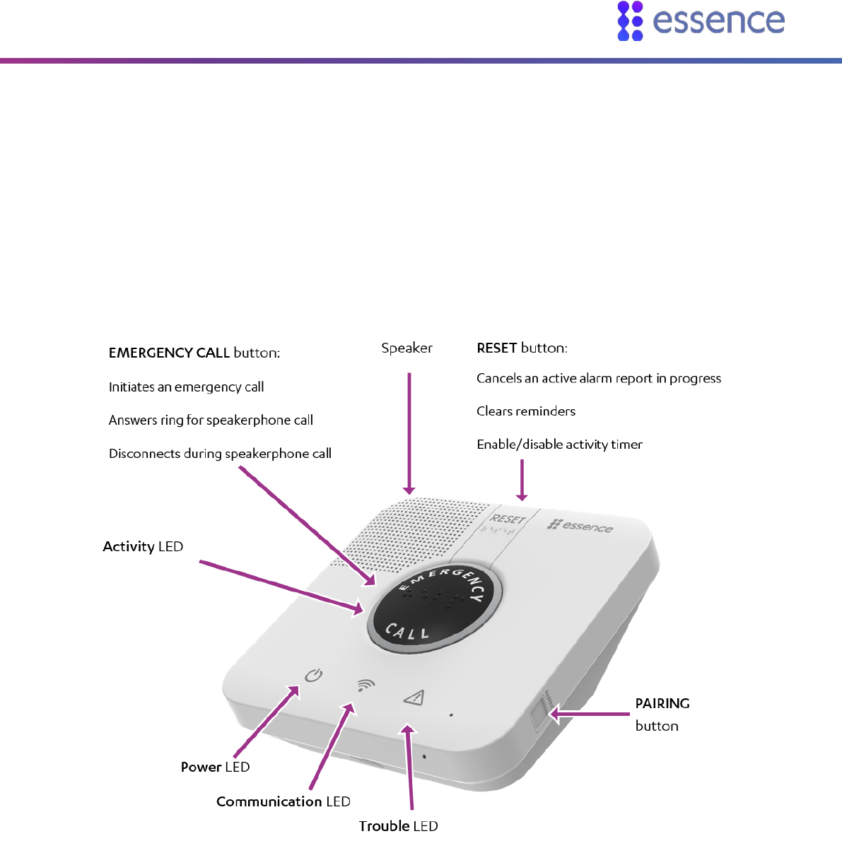
Figure 1: The Care@Home™ Control Panel
The CP includes a high-volume speaker, and a sensitive microphone. The EMERGENCY CALL and
RESET buttons on the CP, include molded and raised braille characters, for ease of recognition by
visually impaired residents.
Overview
4 Care@Home™ Control Panel Next Generation User Guide
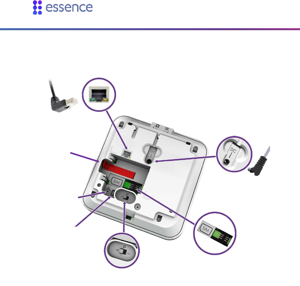
Figure 2: The Back of the CP
The CP has a rechargeable battery as a backup power source. The CP has an ON/OFF switch, allowing
the CP to be turned OFF for storage, or while the resident is away for long periods of time.
Power switch
LAN port
Test mode
pinhole
Backup
battery
Power adapter
Mini-USB for
service
personnel
SIM card

Overview
Care@Home™ Control Panel Next Generation User Guide 5
1.1. Communications with the Monitoring Station
The CP communicates with the monitoring station using a cellular network or a standard telephone
network Public Switched Telephone Network (PSTN) landline or Ethernet, according to the CP version.
Cellular and Ethernet communication are supported by Pro, Family, and PERS. PSTN communication is
supported by PERS. If there is a communications failure, the CP saves messages and sends them when
communications are restored.

Installing the CP
6 Care@Home™ Control Panel Next Generation User Guide
2. Installing the CP
Installing the CP includes the following:
Determining the best location for the CP
Setting up the CP
Wall Mounting the CP
Configuring the CP parameters
2.1. Determining the Best Location for the CP
Survey the premises to determine the best location for the CP It is recommended that you install the
CP installation in either the living room or the master bedroom, in a location which is:
Central within the premises
Provided with sufficient cellular reception
For a PSTN model, near a telephone jack
For a LAN model, near a LAN connection
Convenient for the resident to access, yet not where the CP would attract attention from
unauthorized users
Where the CP speakerphone can be heard throughout the premises
Away from concrete walls to eliminate radio frequency (RF) interference
Away from metal obstructions
At least 2 m (6 ft.) from the peripheral devices
2.2. Necessary Items
Ensure you have the following:
Cellular Model
PSTN Model
LAN Model
Rechargeable backup
battery
Power adapter
SIM card – from the
cellular service provider
Rechargeable backup
battery
Power adapter
PSTN telephone jack
dedicated to the CP
Rechargeable backup
battery
Power adapter
LAN port dedicated to the
CP
LAN cable
Installing the CP
Care@Home™ Control Panel Next Generation User Guide 7
PSTN telephone cable for
the CP
2.3. Setting Up the CP
To set up the CP:
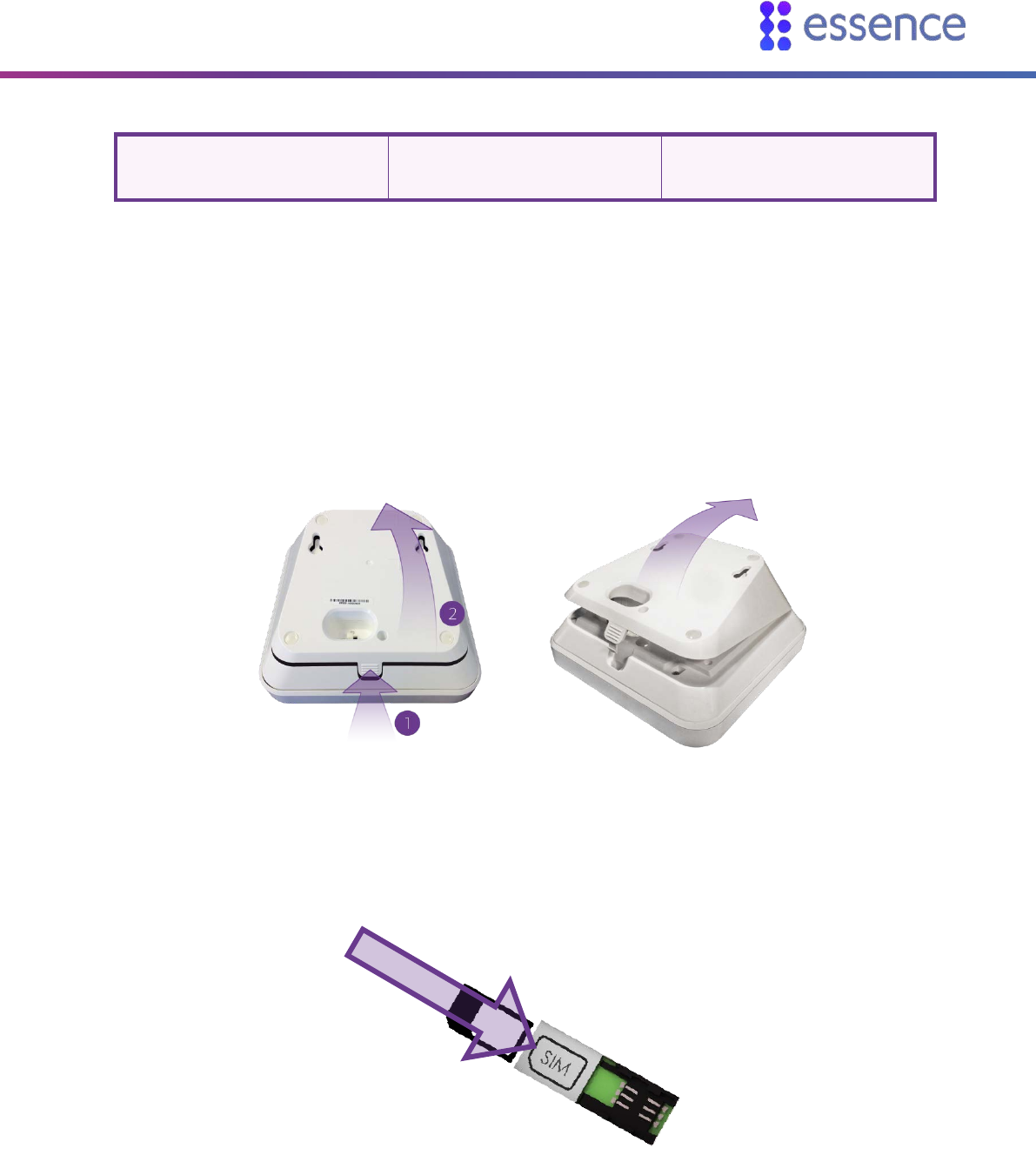
1. Ensure the power switch is in the OFF position.
2. Push the ribbed tab at the bottom of the back cover, and lift the cover off.
Figure 3: Removal of the Back Cover
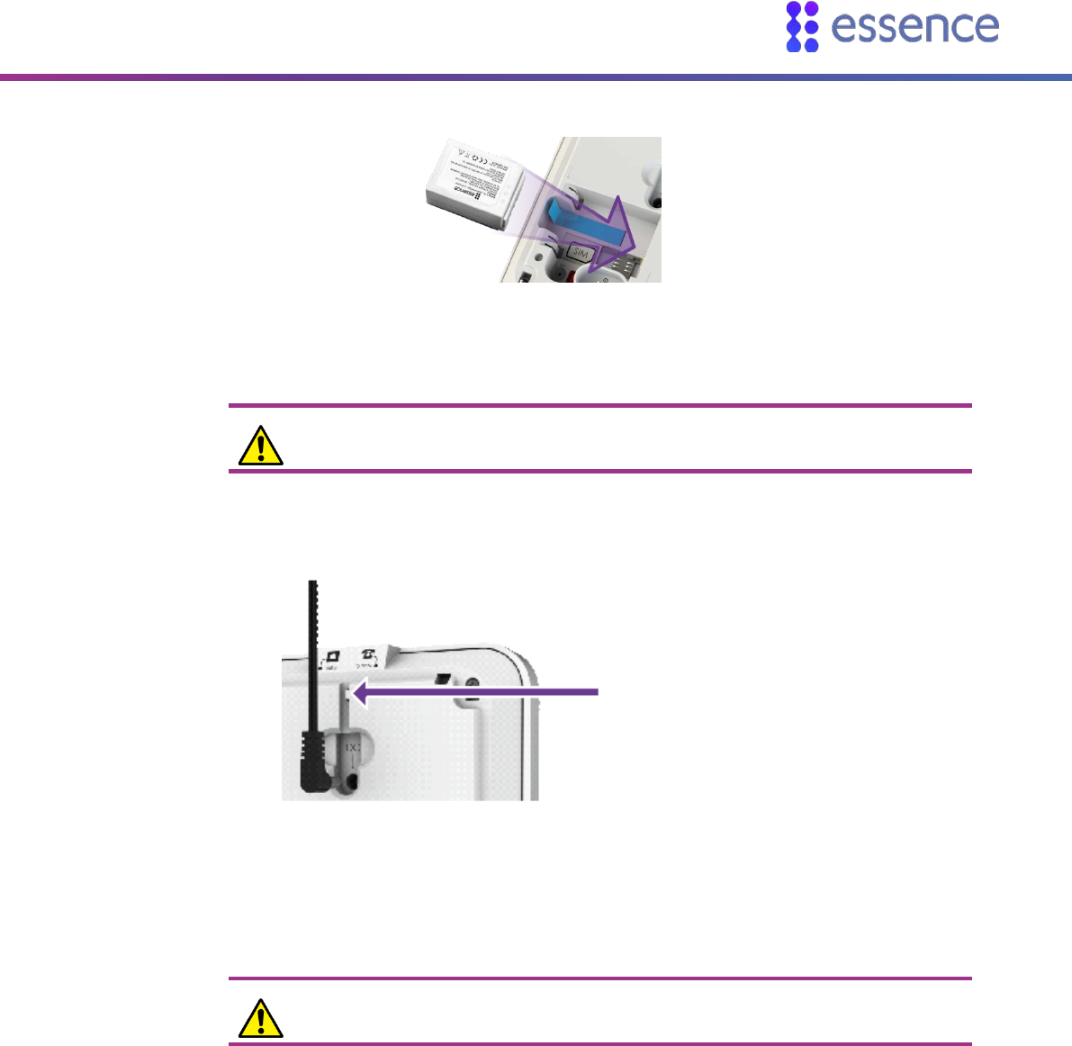
3. For the cellular model, insert the SIM card, with its contacts facing downward.
Figure 4: Insertion of the SIM Card
Installing the CP
8 Care@Home™ Control Panel Next Generation User Guide
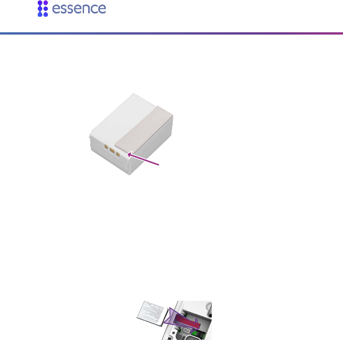
4. For European product versions only, attach the adhesive pad included in the kit, to the backup
battery, such that the pad is on the side closest to the contacts. Make sure to leave space between
the pad and the edge of the battery.
Figure 5: Space Between the Pad and the Battery Edge
5. Insert the backup battery over the battery pull strip, such that:
The printed side of the battery is facing upward
The battery contacts are pointing towards the CP contacts
Ensure that the end of the battery pull strip is showing, and that the strip itself is not blocking the
contacts.
Figure 6: Inserting Backup Battery
Leave space between the pad and
the edge of the battery
Installing the CP
Care@Home™ Control Panel Next Generation User Guide 9
Figure 7: Inserting European Backup Battery
Caution: A new battery can cause damage if it is incorrectly installed.
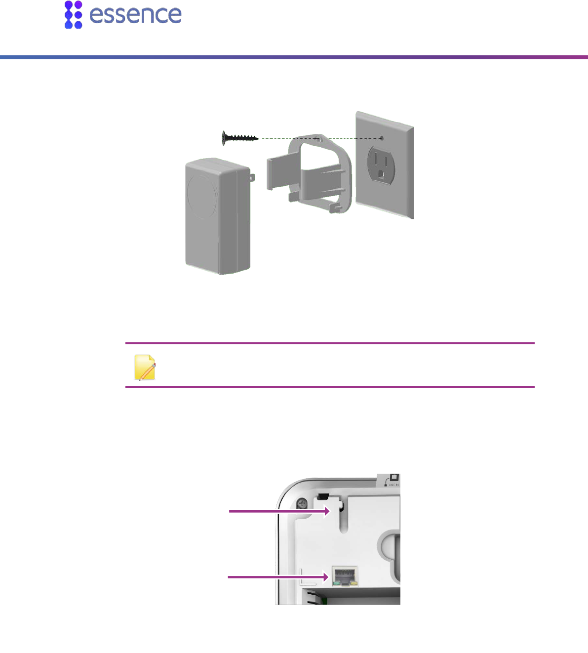
6. Plug-in the power adapter connector into the CP power socket, securing the cable under the tab.
7. Connect the cable to power.
Caution: Do not connect to a receptacle controlled by a switch.
Secure the cable
under the tab
Figure 8: Connecting the Power Adapter’s Cable
Installing the CP
10 Care@Home™ Control Panel Next Generation User Guide
For USA product versions only, you should secure the power adapter cube.
Figure 9: Securing the Power Adapter Cube
NOTE: Install in accordance with the requirements of: The National Electrical
Code, NFPA 70
8. For LAN models, plug the 90° LAN connector into the CP’s LAN port, securing the cable under the
tab. Plug the other end of the LAN cable into your location’s nearest LAN port.
Tab
LAN Port
Figure 10: LAN Port and Tab
Installing the CP
Care@Home™ Control Panel Next Generation User Guide 11
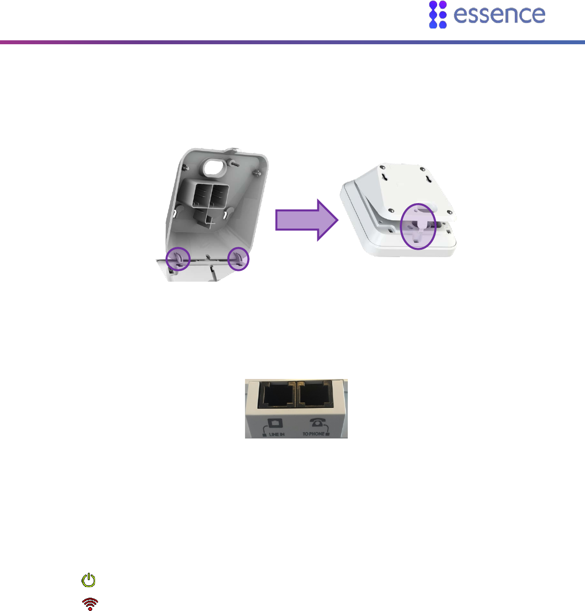
9. Replace the back cover.
Figure 11: Replace the CP Back Cover
10. For the PSTN model, connect the CP to the landline.
Two PSTN phone sockets (RJ-11) are provided on the back of the CP PSTN model:
Figure 12: The PSTN Phone Sockets
i. Connect the phone cable between the LINE IN socket and the home phone jack. The
telephone cable used should be at least of 26 AWG.
ii. Optionally, you can connect a telephone to the TO PHONE socket, using the cable included
in the Care@Home™ PERS kit.
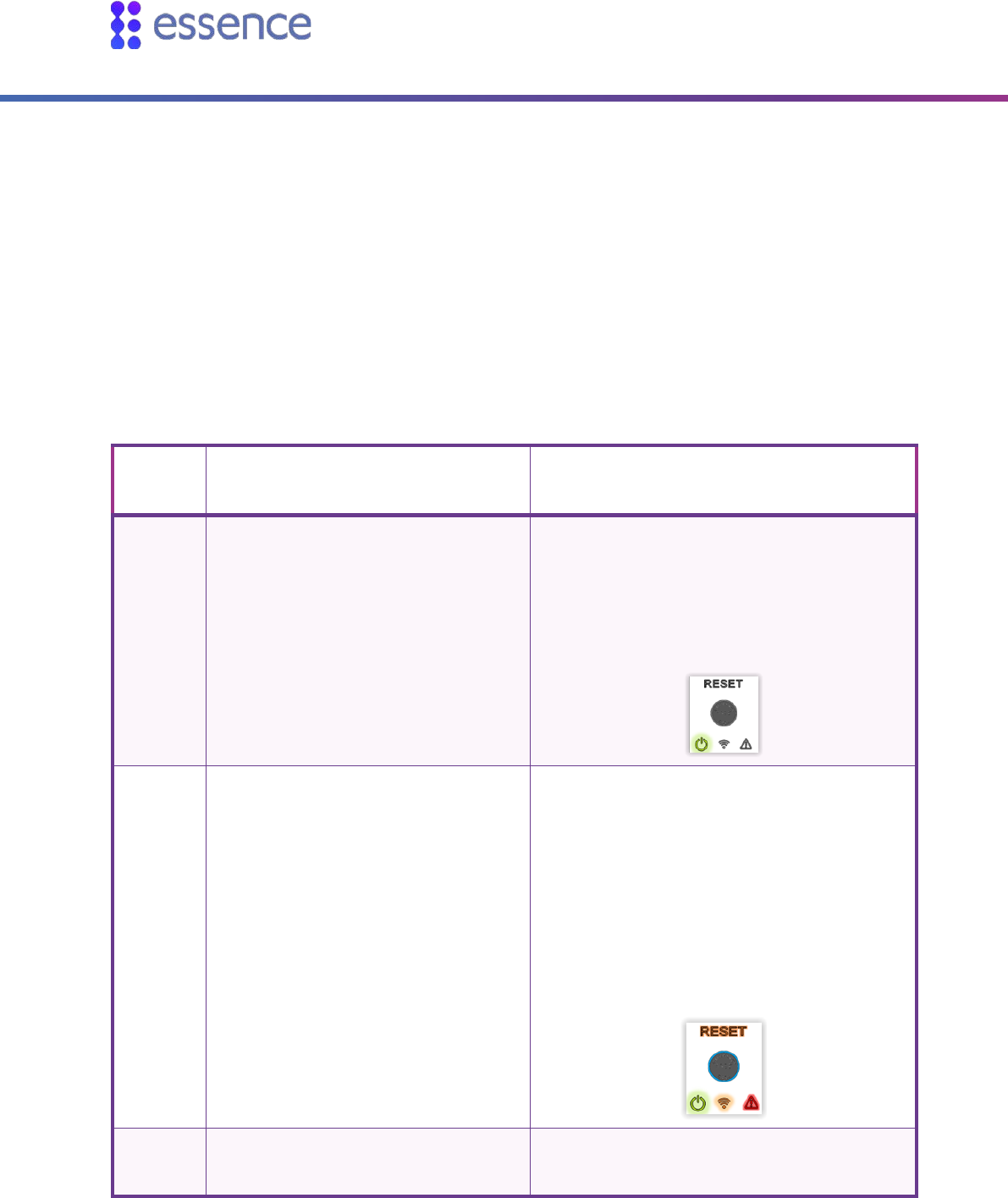
11. Move the power switch to ON. The CP switches to Stand By mode. In this mode:
The Power LED is green.
The Communication LED is red.
In some cases, such as when the CP is pre-configured, the ring around the EMERGENCY CALL
button is blue.
2.4. Wall Mounting the CP
The CP can be placed on a tabletop or mounted on a wall with screws.

Installing the CP
12 Care@Home™ Control Panel Next Generation User Guide
To mount the CP on a wall:
1. Prepare the following equipment:
A drill with a standard bit
Two 3 X 35 DIN 7982 C screws and wall anchors:
A standard Philips screwdriver
2. Choose a flat, smooth, non-concrete wall.
3. Determine the height at which you want to mount the CP. This is usually the eye level of the
resident when seated.
4. At the desired height, drill two holes 7.5 cm (2.95 inches) away from each other horizontally.
Ensure that they are level.
5. Screw the screws into the holes, leaving a space of a few millimeters between the wall and the
screw heads.
6. Remove the back cover of the CP.
7. Align the screw mount holes on the back cover of the CP over the screw heads.
8. Slide the back cover down gently until the screws lock in place.
9. Reattach the CP to the back cover.
2.5. Configuring the CP Parameters
CP parameters are pre-configured to manage and control the CP and the peripherals associated with
the CP. If required, use the Care@Home™ CMS application to adjust the configuration for the
requirements of the resident and the resident’s family.
Refer to the CMS documentation for the version of Care@Home™ installed in the resident’s premises:
PERS: ESUG05071 Care@Home PERS CMS User Guide
Pro or Family: ESUG05074 Care@Home CMS Reference
NOTE: To receive power fail notification, the CMS Mains Failure CP parameter
must be enabled.

Operating the CP
Care@Home™ Control Panel Next Generation User Guide 13
3. Operating the CP
The CP is the core of Care@Home™, communicating with the various peripherals to monitor a
resident's activity, triggering emergency and safety alarms, acting as a speakerphone, and enabling
emergency conversations and remote call-in. In addition, the LEDs on the CP light up to display helpful
information.
3.1. Monitoring a Resident – PRO and Family
The PRO and Family solutions allow the monitoring of a resident's activities with a variety of detailed
reports based on an analysis of the information collected by the peripherals. For information, refer to
ESUG05050 Care@Home Caregiver User Guide.
3.2. Monitoring a Resident - PERS
The PERS solution allows the monitoring of residents with the following features:
Activity Timer
Inactivity Timer
3.2.1 Activity Timer
The activity timer feature is configured with the CMS application, creating time slots during which
resident activity is checked by asking the resident to press the RESET button.
When the activity timer is enabled, the Activity LED is a steady blue
Fifteen minutes before the end of the session, the CP reminds the resident to press the RESET
button, and the Activity LED is a blinking blue
If no activity is confirmed during the session, the CP sounds an announcement that the activity timer
has expired and an activity event is reported to the monitoring station.
3.2.2 Inactivity Timer
The inactivity timer feature is configured with the CMS application, creating time slots during which
resident activity is checked using the sensors on the premises. The CP provides no visual or audible
indications to the resident of an inactivity timer operation.
The CP communicates with the monitoring station when no activity is detected.

Operating the CP
14 Care@Home™ Control Panel Next Generation User Guide
3.3. Emergency Alarms
Emergency alarms are triggered by pressing the EMERGENCY button on the CP.
In addition, an emergency alarm can be triggered by the following devices:
Device Description
Emergency Pendant Advanced (ES700EPA) An emergency panic button with fall
detection capability, worn by the
resident.
Alarm triggered by pressing the panic
button, or when a fall is detected.
Emergency Pendant (ES700EP)
Emergency Pendant Plus (ES7000EPP)
Emergency Pendant Advanced - BC (ES7000EPA – BC)
An emergency panic button, carried or
worn by the resident.
Alarm triggered by pressing the panic
button.
Voice Panic Detector (ES700VPD) Stationary emergency panic button with
active voice detection.
Alarm triggered by pressing the panic
button, pulling out the cord, or calling
out the trigger phrase.
In response to an emergency alarm, the CP communicates with the monitoring station.
3.4. Safety Alarms
Environmental situations, detected by the peripherals, can trigger the CP to sound the following
alarms:
Water leakage – triggered by a flood detector
Extreme temperature – triggered by any of the peripheral devices
Fire – triggered by a smoke detector
The ES700SK2 smoke detector features an internal siren which sounds in addition to the CP alarm if
smoke is detected.
Operating the CP
Care@Home™ Control Panel Next Generation User Guide 15
NOTE: For compliance with the UL 985 and ULC-S545 standards, the ES700SK2
smoke detector must be part of Care@Home™.
3.5. Speakerphone
The CP can be configured to function as a speakerphone only for incoming calls. The speakerphone
does not function if the CP is running on a backup battery. The speakerphone feature can be disabled
by the monitoring station.
When the CP rings, the resident can:
Press the EMERGENCY button to initiate a full-duplex conversation
End the call by pressing the EMERGENCY button again
NOTE: The Care@Home™ Voice Panic Detector (VPD) has a voice extender
capability which also allows the call center of the monitoring station or caregiver
to communicate with the resident. Refer to ESUGSC018 Care@Home VPD User
Guide.
3.6. Emergency Conversation Flow with the CP
The CP supports the following types of conversation flow:
Half-Duplex: only one party can speak at a time. In this mode, DTMF control is supported.
Refer to 3.6.1 Half-Duplex Conversation Flow on page 16.
Full-Duplex: both parties can hear and speak at the same time. The call center operator can
use telephone keypad numbers 1 or 3 (or as otherwise configured) to switch to half-duplex.
NOTE: To configure the keypad assignments, or the Conversation Mode
parameter, refer to the Care@Home™ CMS documentation for the version of
the Care@Home™ system installed on the resident’s premises.
Operating the CP
16 Care@Home™ Control Panel Next Generation User Guide
3.6.1 Half-Duplex Conversation Flow
When a resident presses the EMERGENCY button on their CP, the CP connects to the call center of the
monitoring station. A call center operator responds by managing the half-duplex conversation flow
with the CP, using the telephone keypad. The conversation flow begins with the operator speaking to
the resident.
The following table describes the half-duplex conversation flow triggered when the call center
operator presses the telephone keypad.
Table 1: Half-Duplex Conversation Flow
Keypad
Number Action CP Action
1 The operator speaks to the resident Disables the CP microphone and enables the CP
speaker.
The Power LED is green (On)
The other LEDs are off
3 The operator listens to the resident. Enables the CP microphone and disables the CP
speaker.
The Power LED is green (On)
The Communication and RESET LEDs
are orange
The Trouble LED is red
The Activity Timer ring is blue (On)
2 Increases the speaker volume. Increases the speaker volume one level. There
are five volume levels.

Operating the CP
Care@Home™ Control Panel Next Generation User Guide 17
Keypad
Number Action CP Action
0 Lowers the speaker volume. Lowers the speaker volume one level. There are
five volume levels.
9 Disconnects the operator’s call to the
resident’s CP. Disconnects call.
The following table shows the additional default DTMF codes which apply if Care@Home™ has a VPD
with voice extender capability. Refer to ESUGSC018 Care@Home VPD User Guide.
Table 2: Half-Duplex Conversation Flow with VPD Voice Extender Capability
Keypad
Number Action CP Action
6 Transfers the call to the next device in
the loop of VPD and CP devices.
CP announces:
When talking to CP: "Now talking to
Control Panel"
When using VPD and device location is
known: "Now talking to <location>"
When using VPD and device location is
unknown: "Now talking to VPD <device
ID>"
5 Transfers a call that had previously been
to a VPD to the CP.
CP announces:
"Now talking to Control Panel"
NOTE: DTMF keypad assignments can be configured in the CMS application.
Refer to the Care@Home™ CMS documentation for the version of Care@Home™
installed on the resident’s premises.
Operating the CP
18 Care@Home™ Control Panel Next Generation User Guide
3.7. Making a Remote Call-In
The Remote Call-In feature is configured with the CMS application and enables the operator or the
caregiver to call into the resident’s home via the CP, without the CP sounding or otherwise alerting the
resident.
The operator or the caregiver can use the Remote Call-In feature to try and verify a resident’s status
when, for example, no activity is detected in the resident’s home, or there is some concern about the
resident.
The emergency conversation flow is always half-duplex. Refer to 3.6.1 Half-Duplex Conversation Flow
on page 16.
Refer to the Care@Home™ CMS documentation for the version of Care@Home™ installed on the
resident’s premises.
To make a remote call-in:
1. Call the resident’s CP, using either the CP landline or the CP cell phone number. Wait for the
configured number of rings. The CP answers automatically.
2. Press ‘*’ and enter the four-digit DTMF code.
NOTE: The default DTMF code is 1234. It is recommended to check if the code
has been changed.
3. Manage the half-duplex conversation. Refer to 3.6.1 Half-Duplex Conversation Flow on page 16.
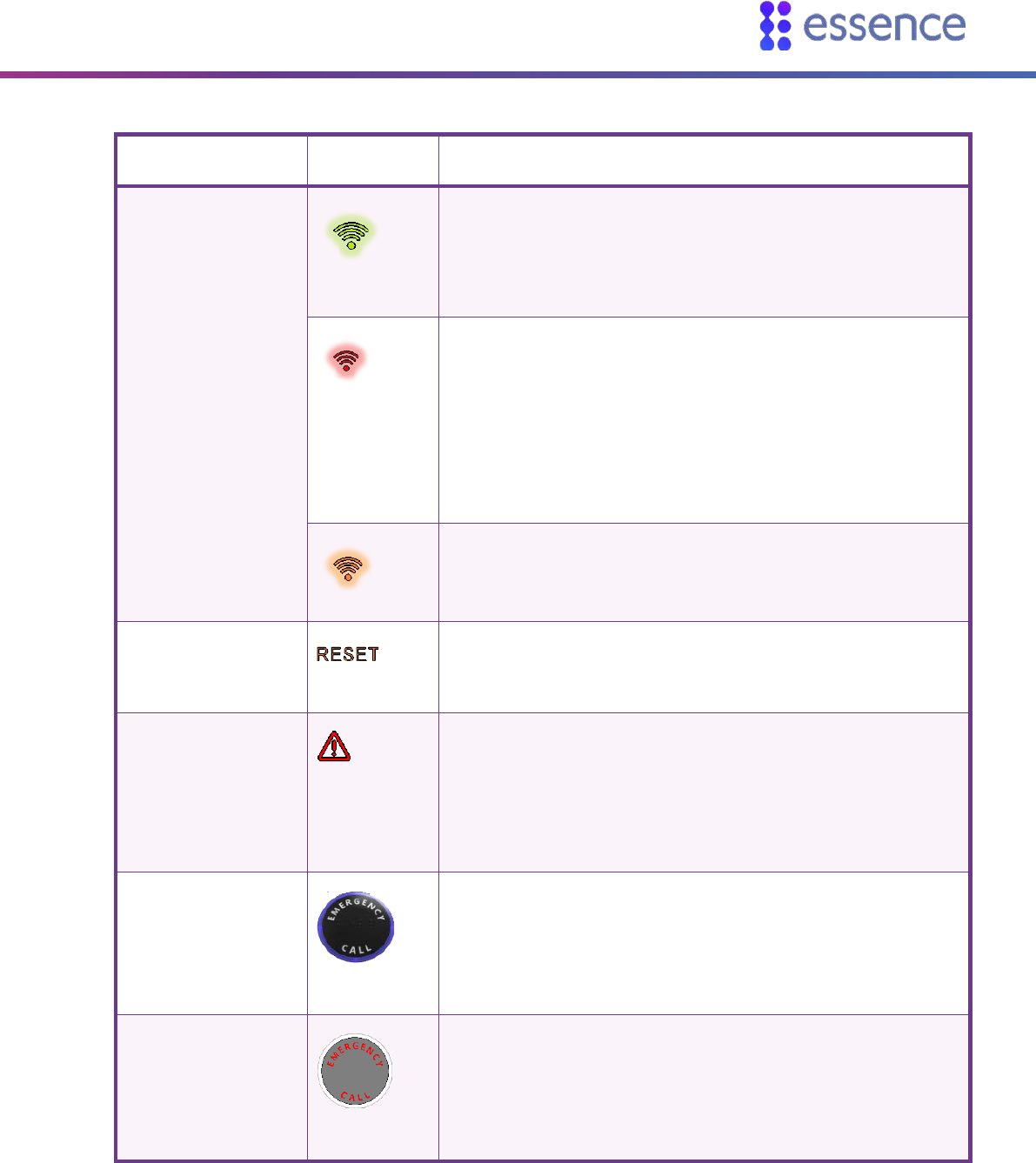
3.8. CP LEDs
The LEDs on the CP display important information about the CP operation.
Table 3: CP LEDs
LED Display Description
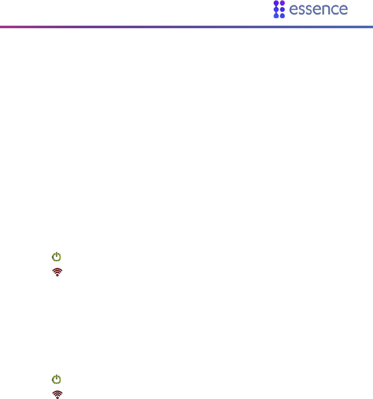
Power
Green
ON – AC power connected
Blinking – Battery operation
OFF – No power or in sleep mode
Operating the CP
Care@Home™ Control Panel Next Generation User Guide 19
LED Display Description
Communication
Green
ON – Communication available
Blinking – Active transmission
Red
ON – Communications failure:
Cellular version: no SIM card, loss of cellular
network, or GSM connectivity test failed
Ethernet version: Ethernet unavailable
PSTN version: PSTN line unavailable
Blinking – Blocked transmission
Orange
ON – An active voice window following an emergency
call
ON – GSM connectivity test is running
RESET
Orange
ON (for three seconds) – Button pressed
Trouble
Red
ON and CP beeps – CP or peripheral malfunction, or
lost communications with the monitoring station
Blinking and CP beeps – Peripheral supervision lost or
low battery power
NOTE: To stop the beeps, press RESET
Activity Timer
Blue ring
ON – Activity timer is on
OFF – Activity timer is off
Blinking – Activity timer expires in less than 15 minutes
EMERGENCY CALL
Red
ON – Message acknowledged
Blinking – Alert in progress

Removing Peripherals -PERS Only
20 Care@Home™ Control Panel Next Generation User Guide
4. Removing Peripherals -PERS Only
When a peripheral paired with the CP, such as an EP, is lost, the monitoring station continues to
receive messages from the CP about the peripheral until the peripheral is removed from the CP. In
such a case, it is recommended to remove the peripherals from the CP.
NOTE: All peripherals are removed. Therefore, you must again pair all the
peripherals with the CP.
To remove the peripherals from the CP:
1. Press the PAIRING button, and hold for five seconds.
2. Press the RESET button, and hold for five seconds. A vocal message from the CP instructs you to
press the PAIRING button to remove all peripherals.
3. Press the PAIRING button. A vocal message from the CP confirms that all devices were removed
from the CP.
Maintaining the CP
Care@Home™ Control Panel Next Generation User Guide 21
5. Maintaining the CP
CP maintenance includes:
Testing the CP
Software updates
Communications maintenance
Backup battery replacement
5.1. Testing the CP
Test the CP at least once a week.
To test the CP:
1. Turn the power switch OFF.
2. Wait 20 seconds.
3. Turn the power switch ON.
4. Wait 20 seconds and check that:
The Power LED is green.
The Communication LED is red.
If both LEDs do not display properly, contact your service provider.
5. Turn the power switch OFF.
6. Wait 20 seconds.
7. Remove the back cover.
8. Unplug the power adapter connector from the CP power socket.
9. Turn the power switch ON.
10. Wait 20 seconds and check that:
The Power LED is green.
The Communication LED is red.
If both LEDs do not display properly, contact your service provider.
11. Plug-in the power adapter connector into the CP power socket.
12. Replace the back cover.

Maintaining the CP
22 Care@Home™ Control Panel Next Generation User Guide
5.2. Software Updates
When there are CP software updates, you must install the updates to your Care@Home™.
See the section on the Remote Boot feature in the Care@Home™ CMS documentation for the version
of Care@Home™ installed on the resident’s premises.
5.3. Communications Maintenance
If the CP uses cellular communications and the quality of the connection becomes unreliable, consult
the cellular service provider to replace your SIM card or repair the connection.
If the CP uses Ethernet communications and the quality of the Ethernet connection becomes
unreliable contact your network service provider.
If the CP uses landline (PSTN) communications and the quality of the landline becomes unreliable,
consult the landline service provider.
5.4. Replacing the Backup Battery
The backup battery recharges automatically when installed in the CP and the CP is connected to AC
power. The battery can continue to be recharged for up to three years.
When the CP reports Low Battery for the CP, the battery is not recharging. Replace the CP battery.
Caution: A new battery can cause damage if it is incorrectly installed. Be careful
to replace the battery only with the same or equivalent type recommended by
the manufacturer. Discard used batteries responsibly.

Specifications
Care@Home™ Control Panel Next Generation User Guide 23
6. Specifications
The following table lists the CP technical specifications.
Table 4: Technical Specifications
Item Data
Part Number ES7502HC
Weight 1.23 lb. (0.56 kg), including adapter and battery
Dimensions (H x W x D) 152 x 152 x 71 mm - 6 x 6 x 2.8 in.
Main Power 100-240 VAC, 50/60 Hz, 500 mA
Backup Battery One Li-Po, 3.7 V, 1400 mAh (North America) or one 2800 mAh
(Europe)
24-hour backup
Rechargeable with three-year battery life
Reporting Modes Cellular model:
SIA IP
DC – 09
SCAIP
Voice Signaling
Debug Printing
Ethernet model:
SIA IP
DC – 09
SCAIP
Voice Signaling
Debug Printing
PSTN model:
SIA
Contact ID
CPC

Specifications
24 Care@Home™ Control Panel Next Generation User Guide
Item Data
Voice Signaling
Debug Printing
4x2
BS 8521:2009
Frequency FSK modulation:
869.225 MHz, 868.3 MHz (Europe and China)
916.5 MHz (North America and Australia)
800 MHz (Israel)
Communication Channels Three different models: PSTN, cellular or Ethernet
Color White and gray
Backup Battery One Li-Po, 3.7 V, 1400 mAh (North America) or one 2800 mAh
(Europe)
24-hour backup
Rechargeable with three-year battery life
Peripheral Devices Up to 64 peripheral devices can be assigned.
Operating temperature 32°F to 120°F (0°C to 49°C)

Specifications
Care@Home™ Control Panel Next Generation User Guide 25
Item Data
Compliance CE, FCC, IC, UL, cUL
EN 60950-1
EN 301 489-1 & EN 301 489-3
EN 300 220-1 & EN 300 220-2; Receiver sensitivity: -108 dBm
EN 50130-4
EN 50130-5 Environmental Class I
EN 50134-2, EN 50134-3, and 50134-5
EN 50136-2:2013 Category C (D3,M3,T1,A1,S0,I0)
Operation Mode-Pass-Through
PSTN model: ANSI/TIA-968-B - Terminal equipment standard
Cellular model: AT&T and PTCRB compliance
EN910-EUR – Compliant with Global Connection (GCF) requirements,
as well as the Global System for mobile communications standard EN
301 511.
NOTE: This equipment has been tested and found to comply with the limits for a Class B digital device,
pursuant to part 15 of the FCC Rules. These limits are designed to provide reasonable protection
against harmful interference in a residential installation. This equipment generates uses and can
radiate radio frequency energy and, if not installed and used in accordance with the instructions, may
cause harmful interference to radio communications. However, there is no guarantee that
interference will not occur in a particular installation. If this equipment does cause harmful
interference to radio or television reception, which can be determined by turning the equipment off
and on, the user is encouraged to try to correct the interference by one or more of the following
measures:
Reorient or relocate the receiving antenna.
Increase the separation between the equipment and receiver.
Connect the equipment into an outlet on a circuit different from that to which the receiver is
connected.
Consult the dealer or an experienced radio/TV technician for help.
Changes or modifications to this equipment not expressly approved by the party responsible for
compliance (Essence Security International Ltd.) could void the user’s authority to operate the
equipment.

Specifications
26 Care@Home™ Control Panel Next Generation User Guide
WARNING! To comply with FCC RF exposure compliance requirements, the device should be located
at a distance of at least 20 cm from all persons during normal operation. The antennas used for this
product must not be co-located or operated in conjunction with any other antenna or transmitter.
This device complies with FCC Rules Part 15. Operation is subject to the following
two conditions:
1. This device may not cause harmful interference, and
2. This device must accept any interference received, including interference
that may cause undesired operation

Legal Notice
Care@Home™ Control Panel Next Generation User Guide 27
Legal Notice
Usage of this document, and all information (including product information) provided within, are subject to the following terms and conditions, and all
applicable laws. If you do not agree with these terms, please do not access or use the remainder of this document.
This document contains highly confidential information, which is proprietary to Essence SmartCare Ltd. and/or its affiliates (hereafter, "Essence"). No part
of this document's contents may be used, copied, disclosed or conveyed to any third party in any manner whatsoever without prior written permission
from Essence.
The information included in this document is intended for your knowledge and for negotiation purposes only. Essence makes no implicit representations
or warranties with respect to such information.
The information included in this document is subject to change without notice. Any decision to rely on the information contained herein shall be at your
sole responsibility, and Essence will not accept any liability for your decision to use any information or for any damages resulting therefrom.
Certain laws do not allow limitations on implied warranties or the exclusion or limitation of certain damages. If these laws apply to you, some or all of the
above disclaimers, exclusions, or limitations may not apply to you.
By using the information contained herein, you agree that the laws of the State of Israel, without regard to principles of conflict of laws, will govern any
dispute of any sort that might arise between you and Essence regarding the information contained herein, and any such dispute shall be settled
exclusively in the competent courts of Tel Aviv-Jaffa, Israel.
All registered or unregistered trademarks, product names, logos and other service marks mentioned within this document are the property of Essence, or
their respective owners. Nothing contained herein shall be construed as conferring by implication, estoppels, or otherwise any license or right, either
express or implied, under any patent or trademark of Essence or any third party. No use of any trademark may be made without the prior written
authorization of Essence.
This document and all of its contents are protected intellectual property of Essence. Any copying, reprinting, reuse, reproduction, adaptation,
distribution or translation without the prior written permission of Essence is prohibited.
Please check your End User License Agreement (EULA) for terms and conditions.
© 2018 All rights reserved to Essence SmartCare Ltd.
For more information, please contact: Essence SmartCare Ltd.
12 Abba Eban Avenue,
Ackerstein Towers Bldg. D
Herzliya Pituach, 4612001 Israel
www.essence-grp.com
Tel: +972-73-2447777
Fax: +972-9-7729962