Essence Security ES800MGL Magnet Sensor User Manual Installation Guide
Essence Security International ltd. Magnet Sensor Installation Guide
Users Manual

WeR@Home™
Installation Guide
ESUGSL019
Version 2.3
January 2018

Table of Contents
2 WeR@Home™ Installation Guide
Table of Contents
1. Introduction ........................................................................................................................................... 3
2. Installing WeR@Home™ .......................................................................................................................... 5
2.1. Preparing the Required Equipment ............................................................................................ 5
2.2. Downloading the WeR@Home™ App ......................................................................................... 6
2.3. Installing the WeR@Home™ Hub ................................................................................................ 6
2.3.1 Choosing a Location ..................................................................................................... 7
2.3.2 Setting up the Hub ........................................................................................................ 7
2.3.3 Registering the Hub ..................................................................................................... 8
2.4. Activating the Remote Control ................................................................................................. 10
2.5. Installing the Peripheral Devices ................................................................................................ 11
2.5.1 Installing a Motion Detector ....................................................................................... 12
2.5.2 Installing a Camera Detector ....................................................................................... 14
2.5.3 Installing a Door/Window Sensor................................................................................ 17
2.5.4 Installing a Siren .......................................................................................................... 22
2.5.5 Installing a Tag Reader and Tag .................................................................................. 24
2.5.6 Installing a Flood Detector ..........................................................................................29
2.5.7 Installing a Universal Transmitter ................................................................................ 31
2.5.8 Installing a Z-Wave Plus Extender ................................................................................ 33
2.5.9 Installing an HD Camera ............................................................................................. 34
2.6. Installing a Smart Repeater ...................................................................................................... 34
2.6.1 Finding a Suitable Location ........................................................................................ 34
2.6.2 Setting up the Repeater .............................................................................................. 35
2.6.3 Adding Peripheral Devices to the Repeater ................................................................ 36
2.7. Testing the Signal Strength of Peripheral Devices .................................................................... 37
3. Setting-Up Your WeR@Home™ ............................................................................................................. 38
Technical Specifications ..................................................................................................... 39
Pairing a Device .................................................................................................................. 50
The WeR@Home™ Kit .......................................................................................................... 51
Installing with Screws ......................................................................................................... 52
Installing a Pet Immune Lens .............................................................................................. 59
Battery Information ........................................................................................................... 64
Legal Notice .................................................................................................................................................. 65
Introduction
WeR@Home™ Installation Guide 3
1. Introduction
WeR@Home™ is based on a combination of independent components designed to help you manage
your home activities. The floor plan of your home determines the arrangement of the components
and their placement in your home. Work with your service provider to determine the peripherals you
would like to install initially. In the future, you can add more peripherals as needed.
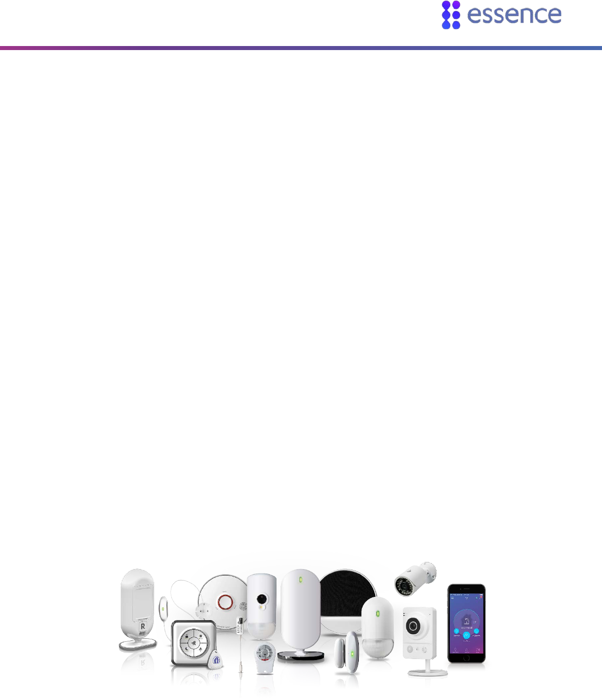
WeR@Home™ includes the following devices:
Hub
Remote Control (Key Fob)
Motion Detector
Camera Detector
Door/Window Sensor
Siren
Tag Reader and Tag
Flood Detector
Universal Transmitter
Z-Wave® Plus Extender
Smoke Alarm
Smart Repeater
For information about the maximum number of each peripheral device allowed in a
WeR@Home™ hub’s system configuration, refer to Maximum System Configuration per Hub on page
46.
Figure 1: WeR@Home™ Product Suite

Introduction
4 WeR@Home™ Installation Guide
NOTE: Some features described in this guide may be disabled depending on
your service level. For information about different service levels, or to change
your service level, contact your service provider.
Installing WeR@Home™
WeR@Home™ Installation Guide 5
2. Installing WeR@Home™
The WeR@Home™ installation involves the deployment of the WeR@Home™ hub and peripherals in
your home. This guide provides the deployment instructions for the hub and each device type.
Installing WeR@Home™ includes the following:
Preparing the required equipment
Downloading the WeR@Home™ app
Installing the WeR@Home™ hub
Installing the peripheral devices
NOTE: For information about the smoke alarm, refer to the ESUG05023
WeR@Home™ Smoke Alarm User Guide.
2.1. Preparing the Required Equipment
Ensure you have the following before you install WeR@Home™:
AA alkaline batteries for the devices, as listed in Battery Quantities and Specifications on page
64. Remember to recycle your used batteries.
WARNING! A new battery can explode if it is incorrectly installed.
If you are using cellular communications, a SIM card is either provided by your distributor or can
be purchased from your cellular service provider.
NOTE: Contact your cellular service provider for APN support.
If you are using mounting-tape for installation, the tape is included. If you are using screws for
installation, refer to Appendix D Installing with Screws on page 52.
Installing WeR@Home™
6 WeR@Home™ Installation Guide
2.2. Downloading the WeR@Home™ App
You can download the WeR@Home™ app from the Apple® App Store or the Google™ Play Store. Make
sure your device meets the following requirements:
Apple: iOS 8.0 or later
Android™: OS 4.1.2 or later
Scan the QR code to download the app.
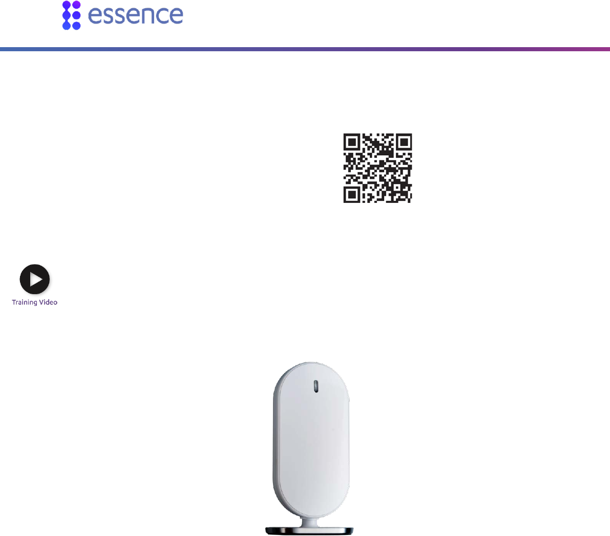
2.3. Installing the WeR@Home™ Hub
The central component of WeR@Home™ is the two-way, wireless WeR@Home™ hub. The hub manages
the peripheral devices, acts a gateway to the Essence Cloud, and communicates with the Essence
servers which provide data to the app.
Figure 2 – The Hub
You can install one or more hubs in WeR@Home™. To install an additional hub in an existing
WeR@Home™ network, see the section Working with Multiple Places in the ESUGSL018 WeR@Home™
User Guide.
Installing the hub includes the following:
Choosing a location
Setting up the hub
Registering the hub
Installing WeR@Home™
WeR@Home™ Installation Guide 7
2.3.1 Choosing a Location
To choose a location, consider the following:
Install on a flat surface in a central location.
If you are using internet communications (LAN) for your external communications channel,
install close to your internet modem or router.
If you are using cellular communications for your external communications channel or as a
backup, choose a location with adequate cellular reception.
It is recommended to position the hub at least 1 m (3.3 ft.) away from the planned peripheral
locations.
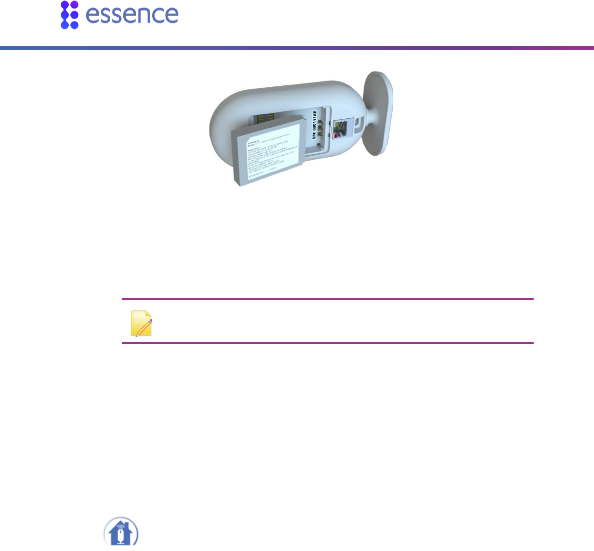
2.3.2 Setting up the Hub
To set up the hub:
1. Plug the power adapter cable into the mini-USB connector on the back of the hub and the power
adapter cube into a power outlet. The LED on the front panel lights up red.
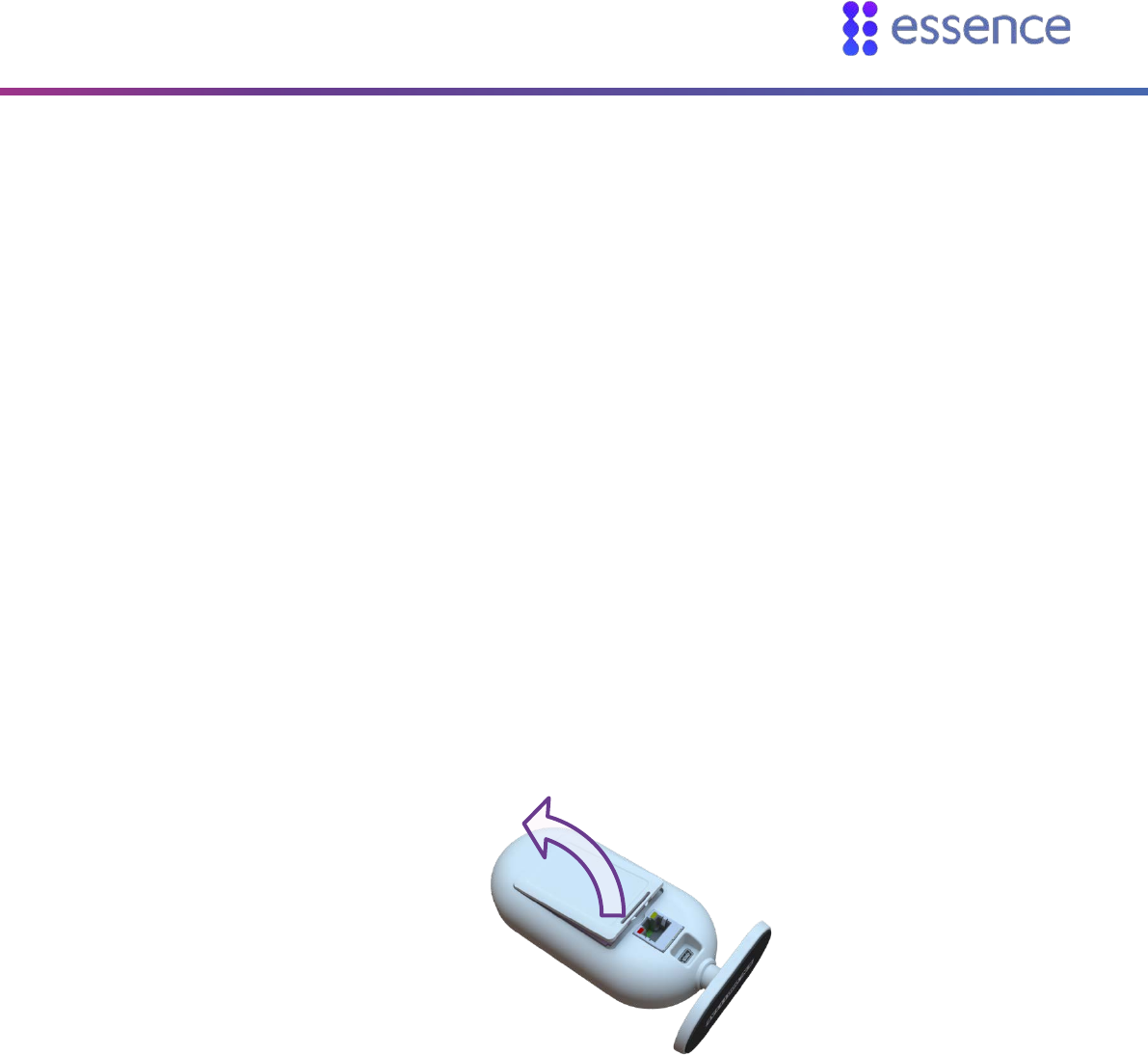
2. Remove the back cover.
Figure 3: Remove Back Cover
3. If you are using a cellular channel, ensure that the SIM card is securely installed.
4. Insert the backup battery into the battery compartment, above the SIM card, such that the battery
label faces upward and the battery contacts face the hub’s base.
Installing WeR@Home™
8 WeR@Home™ Installation Guide
Figure 4: Insert Backup Battery
5. If you are using your LAN, plug the LAN cable into the network port on the back of the hub and the
other end of the cable into the Internet router or modem. The LED on the front panel lights up
orange.
NOTE: If both the SIM card and the LAN cable are installed, the LAN cable is the
external communications channel and the cellular channel is used for backup.
6. Return the back cover to the hub.
7. Wait for the hub front panel LED to switch from orange to green. This may take a few minutes.
2.3.3 Registering the Hub
To finish the hub installation, you need to register the hub.
To register the hub:
1. Tap to open the WeR@Home™app. The Login screen appears.
2. Tap Register. The Registration screen appears.
3. Enter the hub’s 8-digit serial number, which can be found on the base of the hub, and tap Next.
The User Type screen appears.
4. Choose the type of user to add to the hub and enter user details as required:
If the user is not registered on another hub, tap New User. The New User screen appears.
Enter the user personal details, according to the table below, and tap NEXT.

Installing WeR@Home™
WeR@Home™ Installation Guide 9
Table 1: New User Registration Information
Field Definition and Instructions
Email Enter the email address to use for your user credentials during login.
This is the email address to which you want the system messages and
notifications sent.
Password Enter the password to use for your user credentials during login.
The password must be at least six characters long. It is recommended to include
capital letters, numbers and special characters, such as “!” or “#”.
Confirm Password Re-enter the password to verify that the password is entered correctly.
Your Name Enter the name you want to appear in the WeR@Home™ app.
Phone Number Enter the number of the mobile device to receive text messages.
If the user is registered on another hub, tap Existing User. For example, tap Existing User
when adding another hub to your WeR@Home™ network. The Existing User screen appears.
Enter your existing user name and password and tap LOGIN. The Hub Configuration
registration screen appears.
5. Enter the hub configuration details, as defined in the table below.
Table 2: Hub Configuration Registration Information
Field Definition and Instructions
Hub Enter a descriptive name that identifies the hub location.
Country Select the country where the hub is located.
Time Zone Select the time-zone for the country you selected in the previous field. The time-zone is used to
synchronize the system clock for the timestamps of email messages and notifications.
Default: UTC.
6. Tap NEXT. The Congratulations screen appears.
7. Tap Continue to App. A message window appears assigning 1234 as your default PIN.
8. Tap Cancel to go to the Home screen.
9. Tap OK to personalize your PIN. For detailed instructions, refer to ESUGSL018 WeR@Home™ User
Guide.
Installing WeR@Home™
10 WeR@Home™ Installation Guide
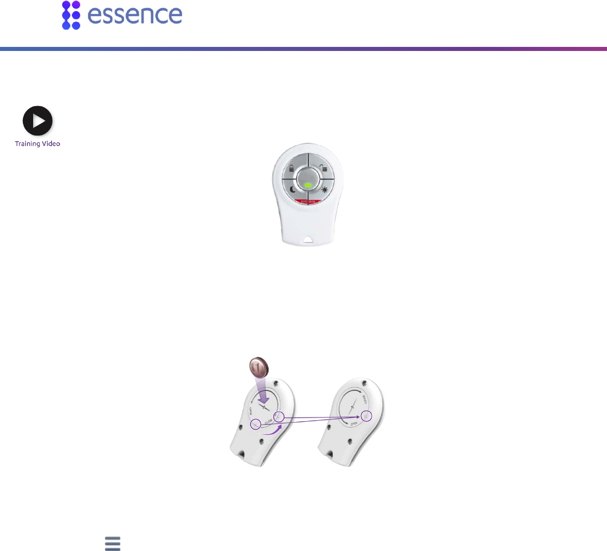
2.4. Activating the Remote Control
The remote control is used to arm and disarm WeR@Home™, and as an SOS button.
Figure 5: The Remote Control
To activate the remote control:
1. Remove the battery compartment cover by inserting a coin into the slot and turning counter-
clockwise until the two dots align.
Figure 6: Releasing the Remote Control Battery Cover
2. Open the WeR@Home™ app.
3. Tap . The main menu appears.
4. Tap DEVICES. The Devices screen appears.
5. Tap Add device. The Add New Devices screen appears.
6. Select Remote Control. The Select Owner User screen appears.
7. Choose the user you want to assign to the remote control. The Remote Control pairing screen
appears.
8. Place the remote control close to the hub.
9. Press any button several times.
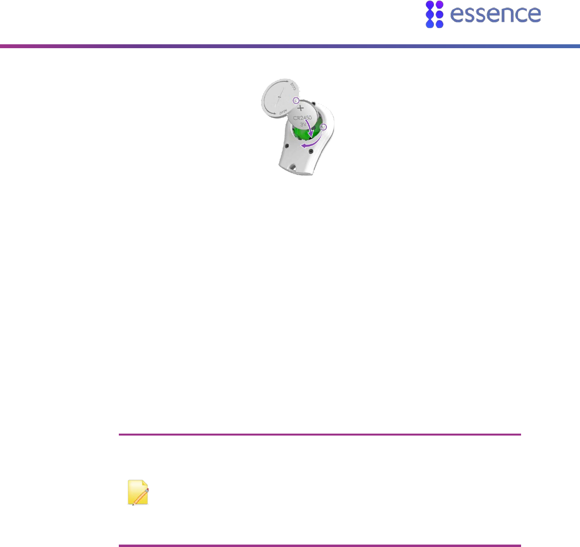
10. Insert the battery into the battery compartment with the + pole facing out and close the cover by
turning it clockwise. The front panel LEDs blink twice.
Installing WeR@Home™
WeR@Home™ Installation Guide 11
Figure 7: Insert the Battery and Close the Remote Control
When pairing succeeds, a screen appears displaying the default remote control name.
11. Tap OK. The remote control appears in the list on the Devices screen.
2.5. Installing the Peripheral Devices
Installing the peripheral devices involves:
Choosing a suitable location
Adding each device to WeR@Home™ by pairing the device with the hub. Pairing allows the
device to communicate with the hub. Devices included in a kit are pre-paired.
Installing the device in the chosen location
NOTE:
If there are difficulties in communications between the hub and an
installed device, consider using a smart repeater. Refer to 2.6 Installing a
Smart Repeater on page 34.
Peripherals are installed using mounting-tape. As an alternative, you can
install using screws. Refer to Appendix D Installing with Screws on page 52.
Installing WeR@Home™
12 WeR@Home™ Installation Guide
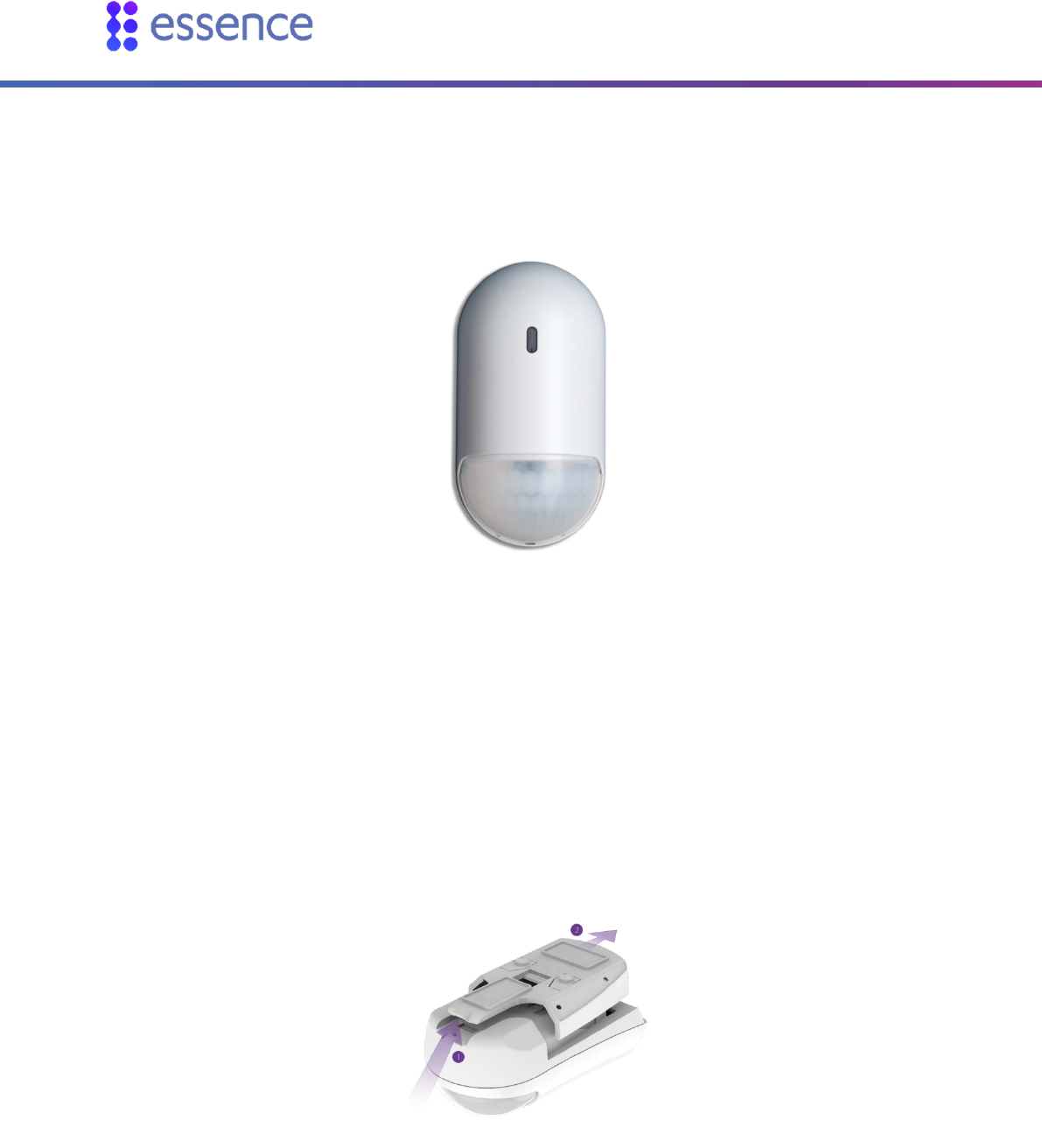
2.5.1 Installing a Motion Detector
The motion detector is a battery-operated, bi-directional, wireless, passive infrared detector.
Figure 8: Motion Detector
To install the motion detector:
1. Choose a location according to the following recommendations:
On a smooth surface, on either a flat wall or in a corner
At a height where the lens is 2.1 m (6.9 ft.) to 2.3 m (7.5 ft.) above the floor
Not opposite a window, facing sunlight, or any other strong light sources
Within 12 m (39.4 ft.) of the desired coverage area
2. Release the motion detector mounting-base by lifting the tab and pushing it forward.
Figure 9: Release the Mounting-Base
3. If the motion detector is not included in the WeR@Home™ kit, pair the motion detector as
described in Appendix B Pairing a Device on page 50. Continue to step 7.
Installing WeR@Home™
WeR@Home™ Installation Guide 13
4. Gently shake the device.
5. Insert two AA alkaline batteries, observing the correct polarity.
Figure 10: Battery Insertion
The LED in the lens compartment flashes red, indicating that the motion detector has powered up
successfully.
6. When prompted, enter a name and/or location for the device and tap OK. The motion detector
appears in the list on the Devices screen.
7. Clean and dry the mounting location surface.
8. Peel off the mounting-tape protective strips, required for the installation location.
Figure 11: Mounting Tape Protective Strips
9. Press the mounting-base into place.
10. If you have a pet on the premises, install a pet immune lens. Refer to Appendix E Installing a Pet
Immune Lens on page 59.
For installing in
a corner
For installing on
a flat wall
Installing WeR@Home™
14 WeR@Home™ Installation Guide
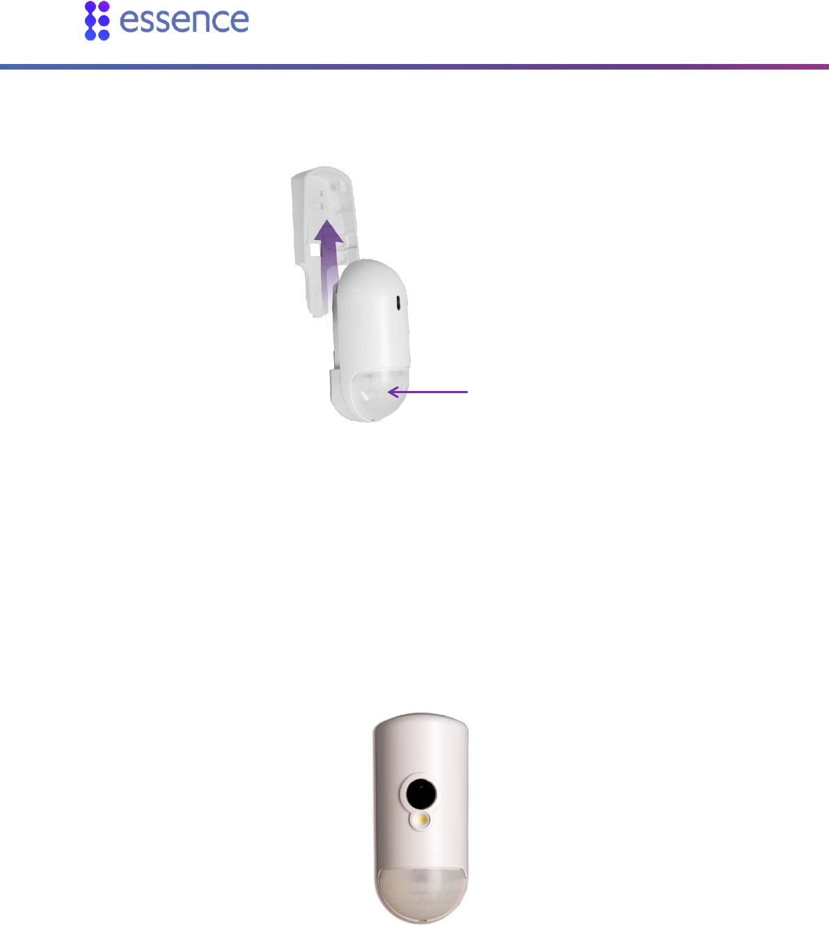
11. Insert the motion detector into the mounting-base until the motion detector clicks into place.
Ensure that the lens is facing downward.
Figure 12: Insert with Lens Facing Downward
12. Test by walking by the motion detector within 30 minutes after you install. The LED should turn
red. Check if events are reported in your app History event list.
2.5.2 Installing a Camera Detector
The camera detector is an indoor sensor combining a battery-operated, bi-directional, wireless
passive infrared motion detector with a JPEG-image-capturing camera.
Figure 13: Camera Detector
Detector Lens
Installing WeR@Home™
WeR@Home™ Installation Guide 15
To install the camera detector:
1. Choose a location according to the following recommendations:
On a smooth surface, on either a flat wall or in the corner
At a height where the camera lens is 2.1 m (6.9 ft.) to 2.3 m (7.5 ft.) above the floor
Not opposite a window, facing sunlight, or other strong light sources
In a position to capture images for monitoring activities such as intrusions, entrance, and
exit
Within 12 m (39.4 ft.) of the desired coverage area.
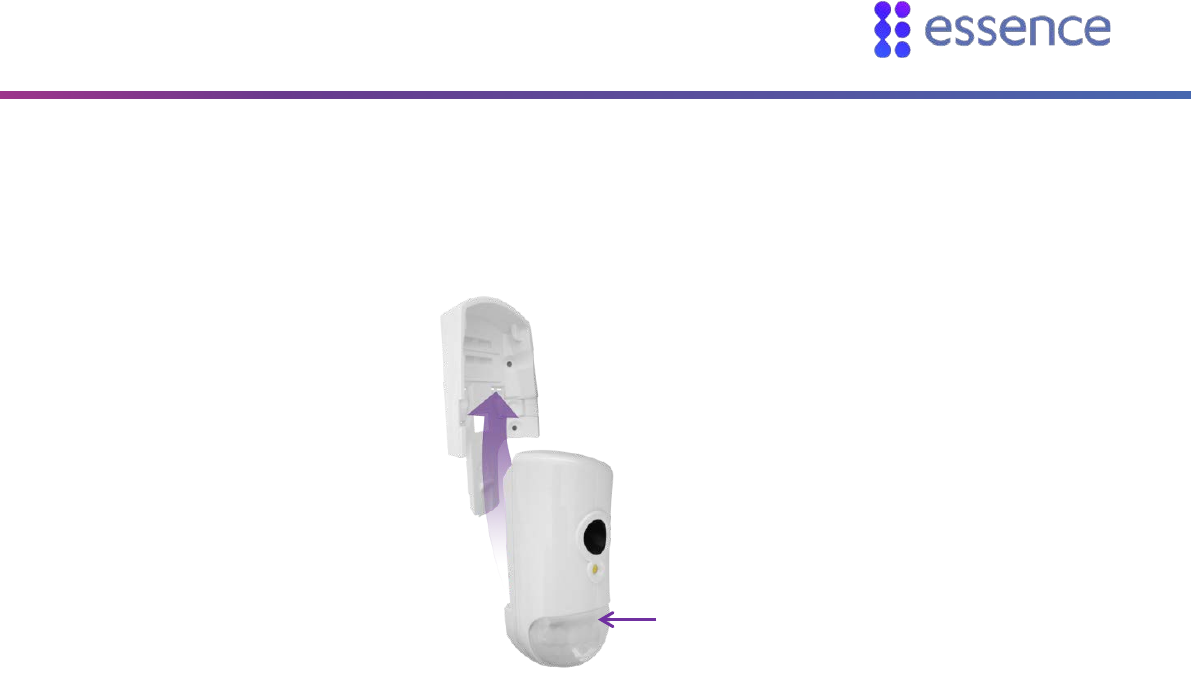
2. Release the camera detector mounting-base by lifting the tab and pushing it forward.
Figure 14: Release the Mounting-Base
3. Open the battery compartment by pushing the tab and lifting the cover up and off.
Figure 15: Battery Compartment Cover
Tab
Installing WeR@Home™
16 WeR@Home™ Installation Guide
4. If the camera detector is not included in the WeR@Home™ kit, pair the camera detector as
described in Appendix B Pairing a Device on page 50. Continue to step 8.
5. Gently shake the device.
6. Insert three AA alkaline batteries, observing the correct polarity.
Figure 16 – Battery Insertion
The LED in the lens compartment flashes red, indicating that the camera detector has powered up
successfully.
7. When prompted, enter a name and/or location for the device and tap OK. The camera detector
appears in the list on the Devices screen.
8. Clean and dry the mounting location surface.
9. Peel off the mounting-tape protective strips, according to the chosen location:
On a flat wall
In a corner
Figure 17: Mounting Tape Protective Strips
10. Press the mounting-base into place.
11. If you have a pet on the premises, install a pet immune lens. Refer to Appendix E Installing a Pet
Immune Lens on page 59.
For installing in
a corner
For installing on
a flat wall
Installing WeR@Home™
WeR@Home™ Installation Guide 17
12. Close the battery compartment.
13. Insert the camera detector into the mounting-base until the camera detector clicks into place.
Ensure that the lens is facing downward.
Figure 18: Insert with Lens Facing Downward
14. Test by walking by the camera detector within 30 minutes after you install. The LED should turn
red. Check if events are reported in your app History event list.
2.5.3 Installing a Door/Window Sensor
The door/window sensor is a magnetic sensor for detecting opening and closing of doors, windows,
cabinets, and other similar items. Optionally, the sensor may include a tamper switch.
This sensor device consists of two parts:
The magnet
The transmitter
Detector Lens
Installing WeR@Home™
18 WeR@Home™ Installation Guide
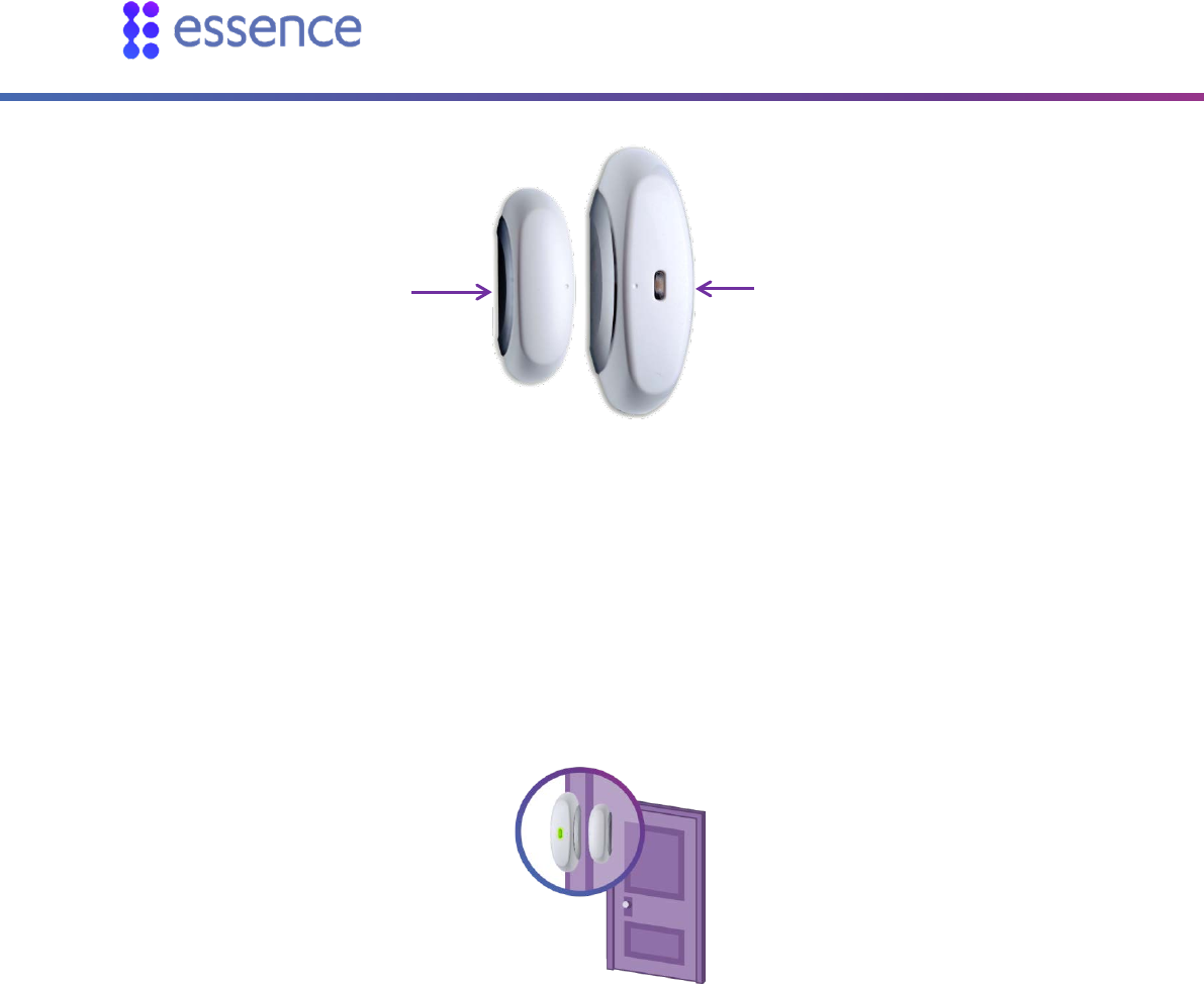
Figure 19: Door/Window Sensor
To install the door/window sensor:
1. Choose a location according to the following recommendations:
A smooth, flat surface on a window, door, or other open/close item
Attach the transmitter to the fixed frame of the open/close item
Attach the magnet to the moving edge of the open/close item
Figure 20: Door/Window Sensor Location Example
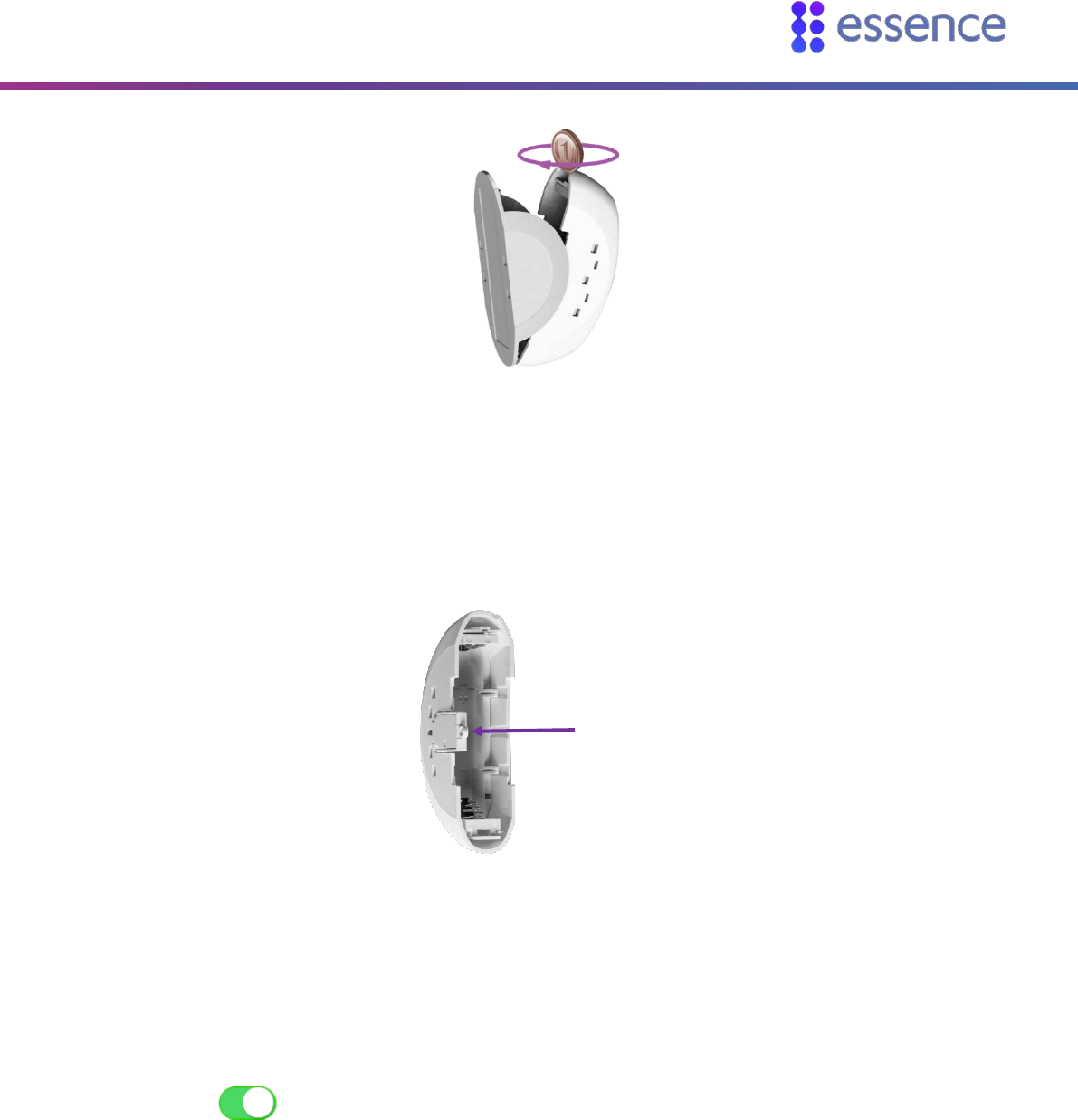
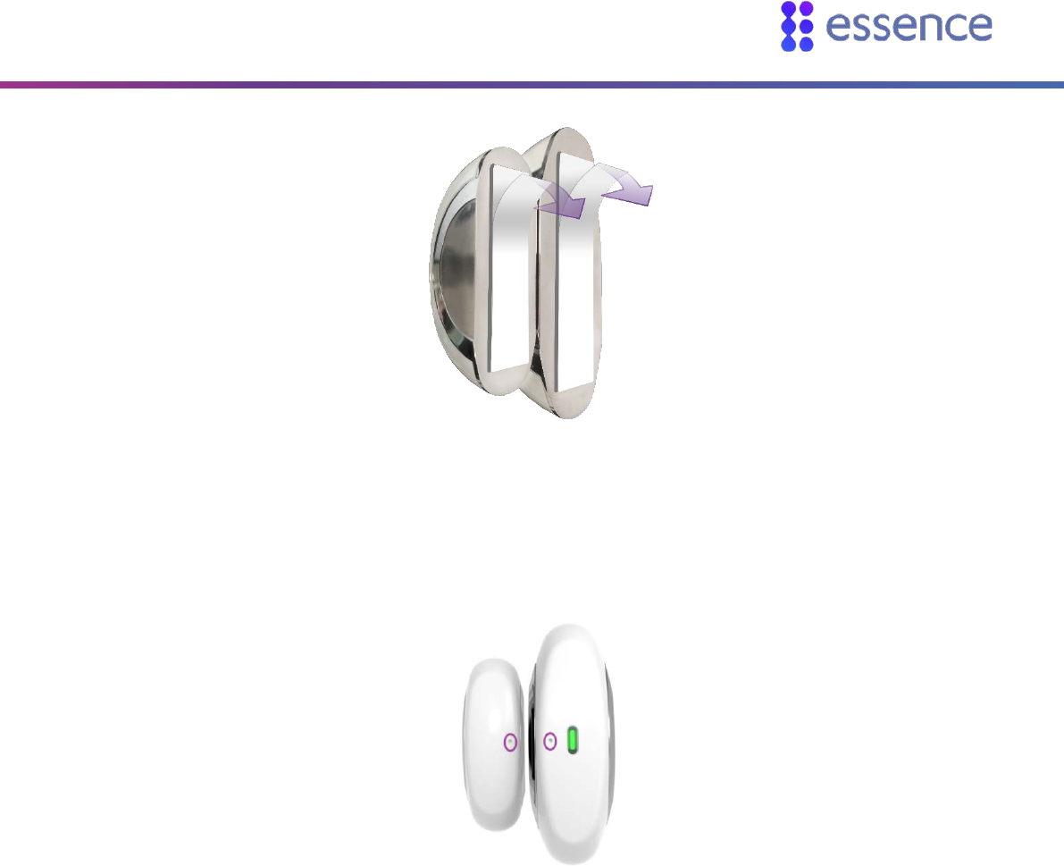
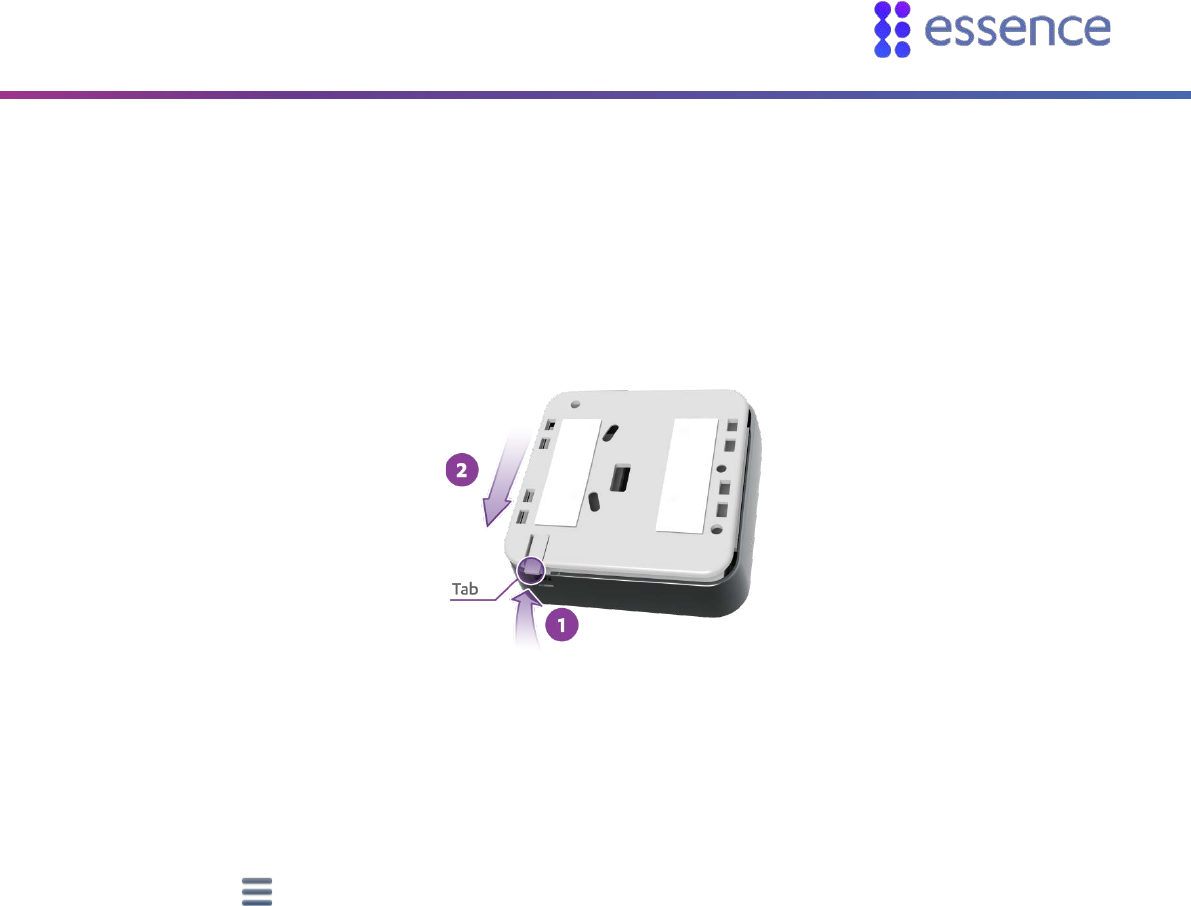
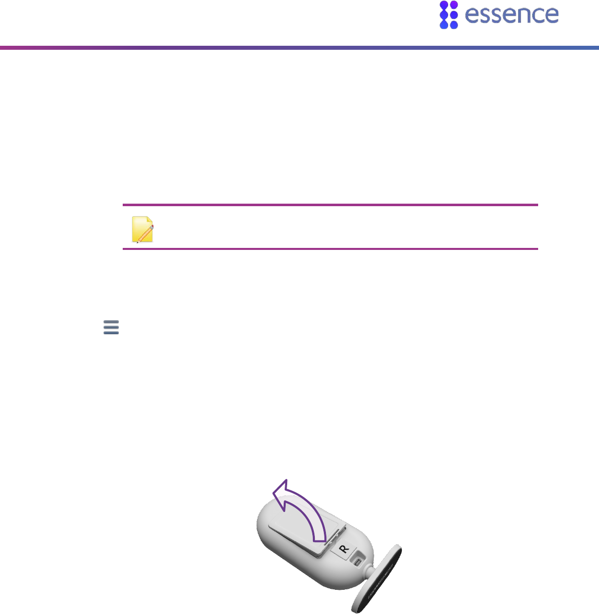
2. Release the transmitter from its mounting base by inserting and twisting a coin to separate the
cover from the base.
Transmitter Magnet
Installing WeR@Home™
WeR@Home™ Installation Guide 19
Figure 21: Releasing the Transmitter
3. If the door/window sensor is not included in the WeR@Home™ kit, pair the door/window sensor as
described in Appendix B Pairing a Device on page 50. Continue to step 7.
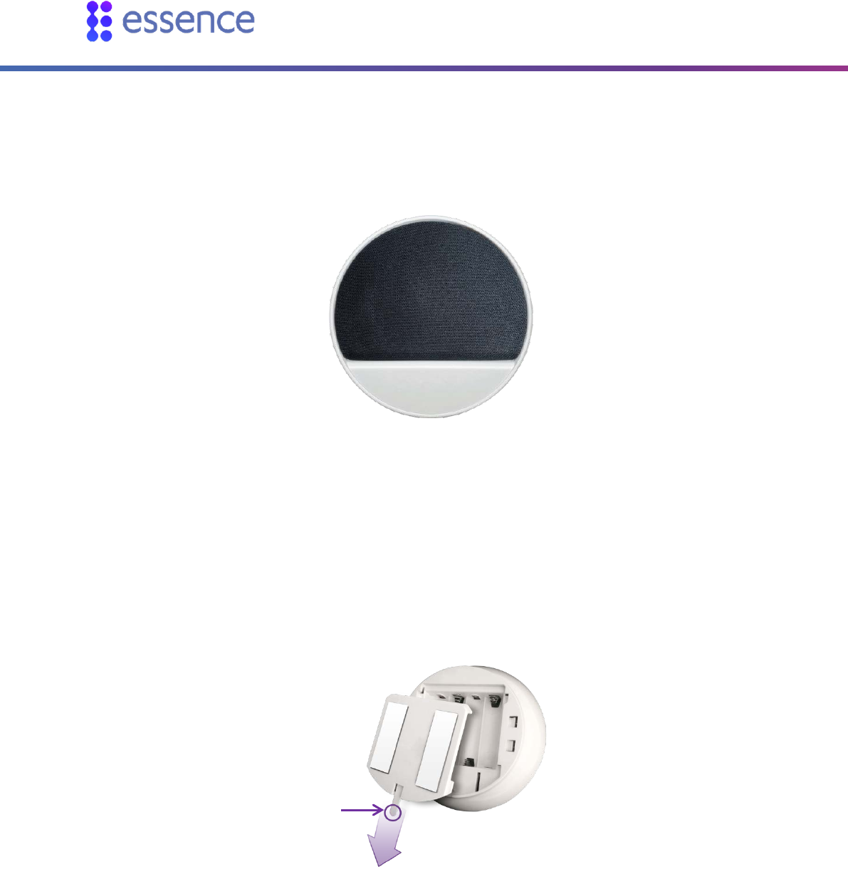
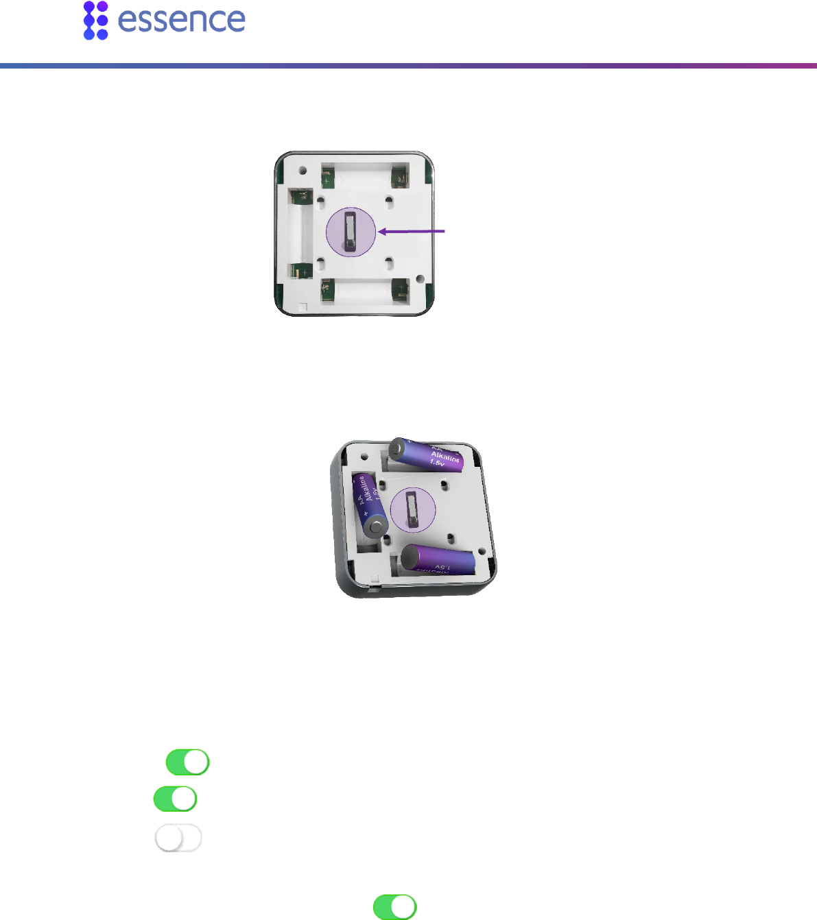
If the device includes a tamper switch, press the switch several times.
Figure 22: Press MGL Tamper
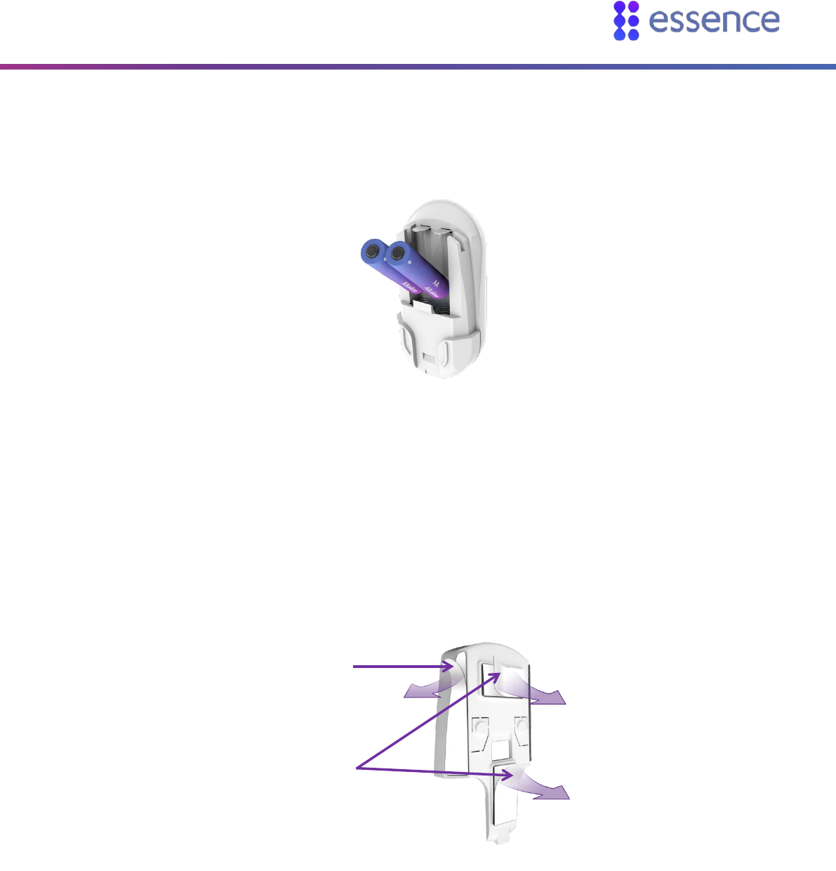
4. Insert one AA alkaline battery observing the correct polarity.
5. When prompted, enter a name and/or location for the device and tap OK.
6. If you want a chime to sound when the door/window opens:
a. Tap Configure
b. Tap
c. Tap OK
Tamper
switch
Installing WeR@Home™
20 WeR@Home™ Installation Guide
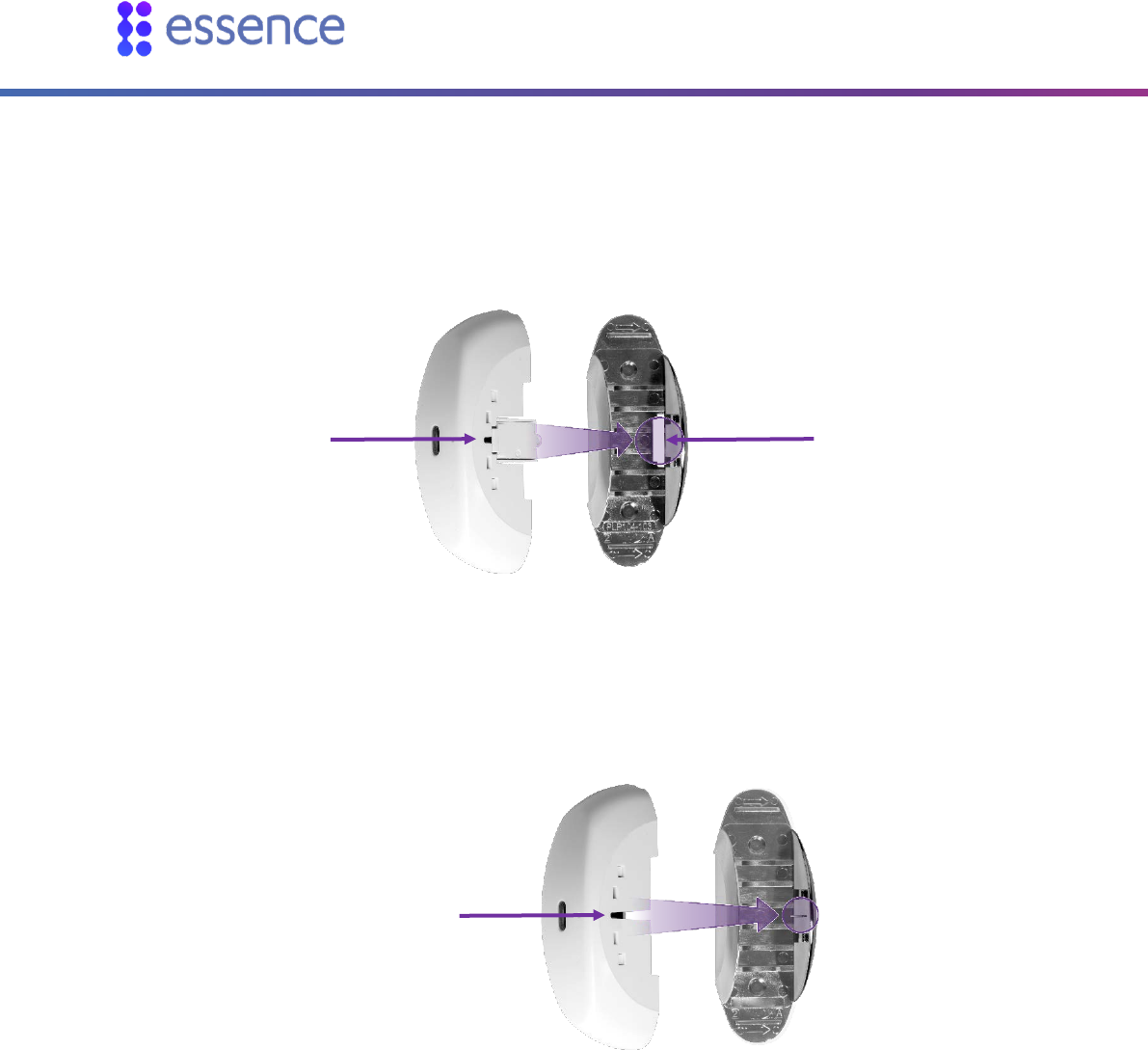
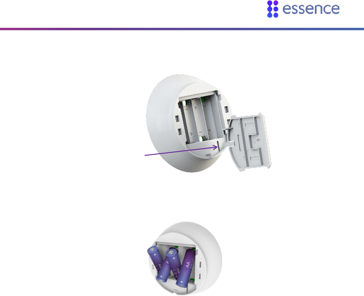
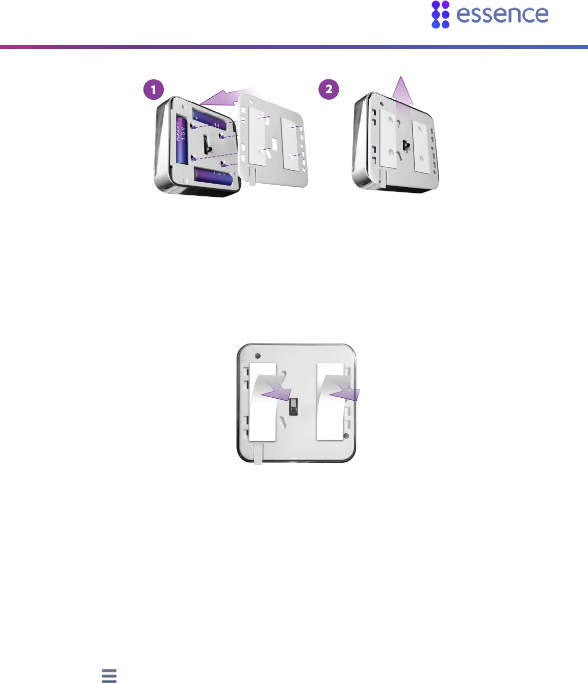
7. Insert the transmitter into the mounting base:
With tamper switch: align the tamper switch with the opening.
Figure 23: Aligning the Tamper Switch Opening
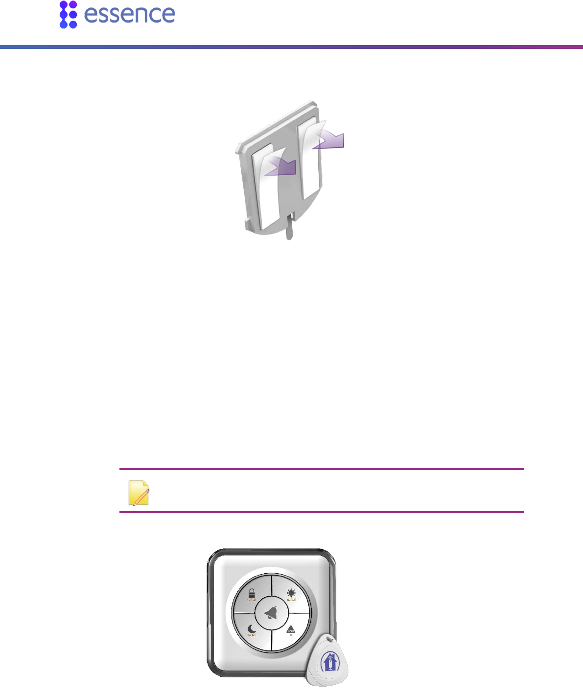
Without tamper switch: align as in the figure below.
Figure 24: Aligning the Transmitter and Base
8. Clean and dry the mounting location surfaces.
9. Peel off the mounting-tape protective strips from both parts.
Tamper
switch Opening
Align here
Installing WeR@Home™
WeR@Home™ Installation Guide 21
Figure 25: Mounting Tape Protective Strips
10. Mount the parts, as follows:
Within 2.5 - 3 cm (1 - 1.2 in.) of each other when closed.
Aligned using the dots.
Figure 26: Dot Alignment of the Door/Window Sensor
11. Test by opening and closing the door or window. The LED should turn red when you open and
green when you close. Check if events are reported in your app History event list.
Installing WeR@Home™
22 WeR@Home™ Installation Guide
2.5.4 Installing a Siren
The siren is a battery-operated, wireless, acoustic warning device. You can also use the siren as a door
bell.
Figure 27: Siren
To install the siren:
1. Choose a location according to the following recommendations:
A smooth surface on a flat wall
Accessible for maintenance yet not easily found by intruders
2. Release the siren mounting-base by lifting the tab and sliding the base in the tab’s direction.
Figure 28: Release Mounting-Base
3. If the siren is not included in the WeR@Home™ kit, pair the siren as described in Appendix B Pairing
a Device on page 50. Continue to step 7.
Tab
Installing WeR@Home™
WeR@Home™ Installation Guide 23
4. Press the tamper switch several times as in the figure below.
Figure 29: Pressing Tamper
5. Insert four AA alkaline batteries, observing the correct polarity.
Figure 30: Siren Battery Insertion
6. When prompted, enter a name and/or location for the device and tap OK. The siren appears in the
list on the Devices screen.
7. Replace the mounting base onto the back of the siren.
8. Clean and dry the mounting location surface.
9. Peel off the mounting-tape protective strips.
Tamper switch
Installing WeR@Home™
24 WeR@Home™ Installation Guide
Figure 31: Mounting Tape Protective Strips
10. Press the siren into place.
2.5.5 Installing a Tag Reader and Tag
The tag reader is a battery operated, wireless, access control and system arming device.
Use your tag to arm and disarm your WeR@Home™. You can configure the tag reader for indoor or
outdoor use. Outdoor use also allows you to use the tag reader as a doorbell. By default, the tag
reader is configured for outdoor use.
NOTE: When you use the tag reader as an indoor device, the tag is not required
to arm your WeR@Home™.
Figure 32: Tag Reader and Tag
Installing WeR@Home™
WeR@Home™ Installation Guide 25
2.5.5.1 Installing the Tag Reader
To install the tag reader:
1. Choose a location that is near the premises’ entrance, indoors or outdoors. Find a smooth, flat,
vertical surface at the chosen location.
2. Release the tag reader mounting base by lifting the tab and sliding the base in the tab’s direction.
Figure 33: Release Mounting Base
3. If the tag reader is included in the WeR@Home™ kit, skip to step 3g.
Add the tag reader to WeR@Home™:
a. Open the WeR@Home™ app.
b. Tap . The main menu appears.
c. Tap DEVICES. The Devices screen appears.
d. Tap Add device. The Add New Devices screen appears.
e. Select Tag Reader. The Tag Reader pairing screen appears as the device scan begins.
f. Place the tag reader close to the hub.
Installing WeR@Home™
26 WeR@Home™ Installation Guide
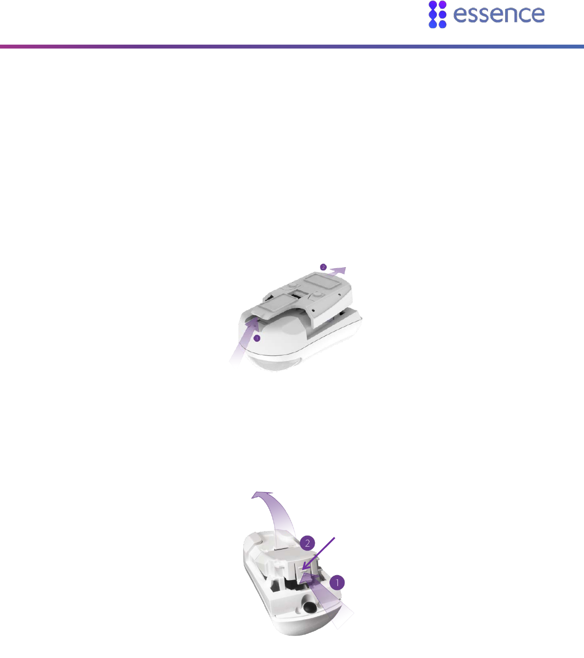
g. Press the tamper switch several times.
Figure 34: Pressing Tamper
h. Insert three AA alkaline batteries, observing the correct polarity.
Figure 35 – Inserting Batteries
If the tag reader is included in the WeR@Home™ kit, skip to step 4.
When pairing is successful, a window appears prompting you to configure the tag reader.
i. Enter a name and/or location for the device.
j. Tap to configure the tag reader:
outdoor use
indoor use
k. If the tag reader is configured for outdoor use and you want to use the tag reader as a
doorbell, tap Configure, for bell, tap , and tap OK. Otherwise, tap OK.
4. Align the mounting base onto the tag reader, guided by the curved latch tabs and the tamper
switch and slide the base into place.
Tamper switch
Installing WeR@Home™
WeR@Home™ Installation Guide 27
Figure 36: Replace the Mounting Base
5. Clean and dry the mounting location surface.
6. Peel off the mounting-tape protective strips.
Figure 37: Mounting Tape Protective Strips
7. Press the tag reader into place.
2.5.5.2 Configuring the Tag Reader for an Access Code
You can configure your tag reader to require an access code together with the tag to disarm
WeR@Home™.
To enable an access code:
1. Open the WeR@Home™ app.
2. Tap . The main menu appears.
3. Tap SETTINGS. The Settings screen appears.
4. Tap Tag Access Code. The TR5 Access Code screen appears.
Installing WeR@Home™
28 WeR@Home™ Installation Guide
5. Select the number of digits you want for your access code (4-10). A confirmation message
appears.
6. Tap Yes.
NOTE: To disable the access code, select None and tap .
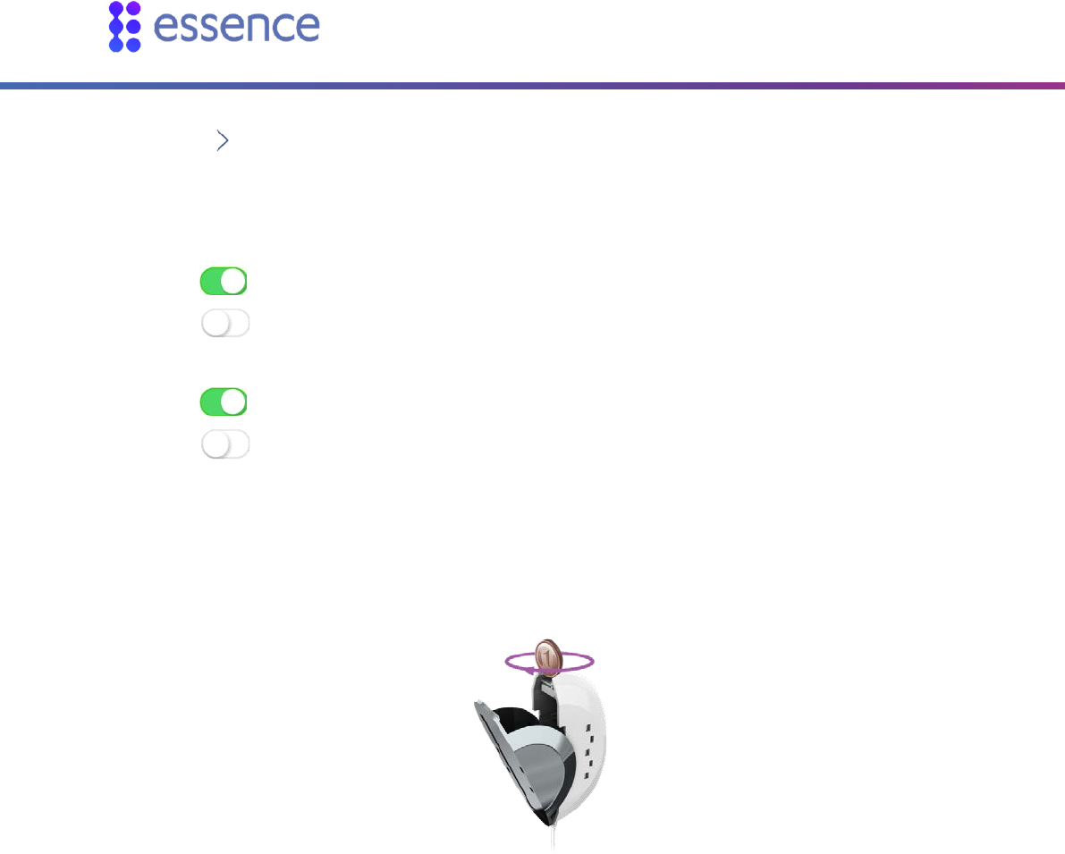
2.5.5.3 Activating Tags
Assign the tag to a user defined in WeR@Home™. To add a user, refer to the section on user
management in the ESUGSL018 WeR@Home™ User Guide.
To add a tag:
1. Open the WeR@Home™ app.
2. Tap . The main menu appears.
3. Tap DEVICES. The Devices screen appears.
4. Tap Add device. The Add New Devices screen appears.
5. Select Tag. The Select Owner User screen appears.
6. Choose the user from the list. The Tag pairing screen appears.
7. Hold the tag against on the tag reader and wait for the tag reader to detect the tag. When
pairing succeeds, the LEDs on the tag reader light up.
If you configured your tag reader to require an access code, a window appears prompting you to
enter the access code.
8. If you configured your tag reader to require an access code, enter the access code.
A window appears, prompting you to enter the tag name.
9. Enter the user’s name as the tag name, and tap OK. The tag appears in the list on the Devices
screen.
Installing WeR@Home™
WeR@Home™ Installation Guide 29
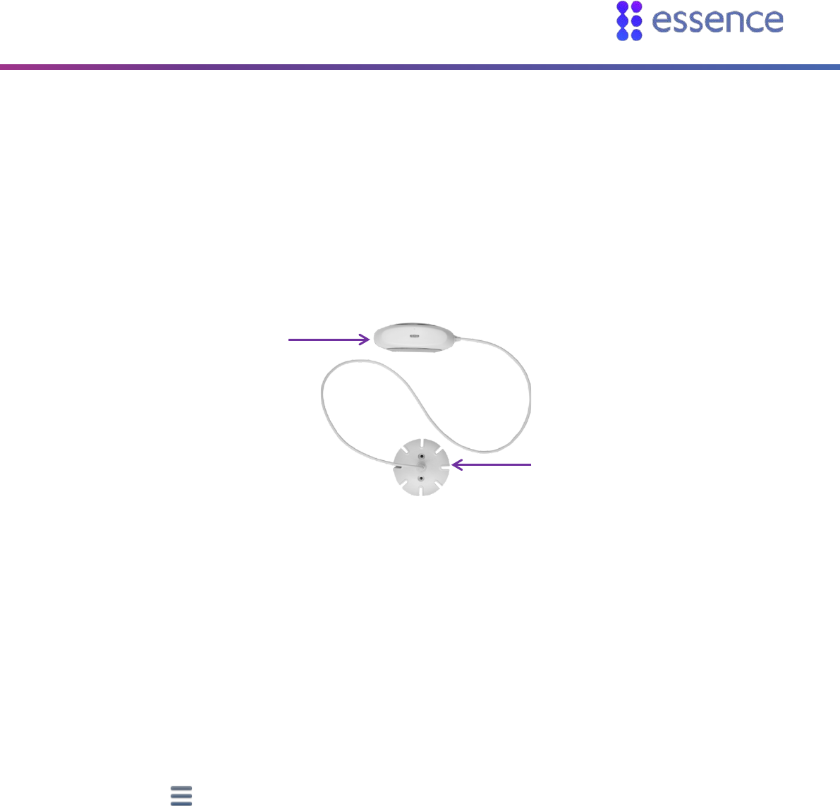
2.5.6 Installing a Flood Detector
The flood detector is a battery-operated, bi-directional, wireless sensor that detects water
accumulation.
The flood detector consists of two connected parts:
The transmitter
The flood sensor
Figure 38: Flood Detector
To install the flood detector:
1. Choose a location according to the following recommendations:
In a location that may flood, like near the washing machine or bathtub
A flat smooth vertical surface for the transmitter
A flat smooth horizontal surface for the sensor
2. If the flood detector is included in the WeR@Home™ kit, skip to step 2g.
Otherwise, add the flood detector to WeR@Home™:
a. Open the WeR@Home™ app.
b. Tap . The main menu appears.
c. Tap DEVICES. The Devices screen appears.
d. Tap Add device. The Add New Devices screen appears.
e. Select Flood Detector. The Flood Detector pairing screen appears as the device scan begins.
f. Place the transmitter close to the hub.
g. Release the transmitter from its mounting base by inserting and twisting a coin to open the
cover.
Transmitter
Flood Sensor

Installing WeR@Home™
30 WeR@Home™ Installation Guide
Figure 39: Releasing the Transmitter
h. Insert one AA alkaline battery, observing the correct polarity.
i. Insert the transmitter into its mounting base. If the flood detector is included in the
WeR@Home™ kit, skip to step 3. When pairing is successful, a window appears prompting you
to enter the device name.
j. Enter a name and/or location for the device and tap OK. The flood detector appears in the list
on the Devices screen.
3. Clean and dry the surfaces of the mounting locations.
4. Peel off the mounting-tape protective strips from both parts.
Figure 40: Mounting Tape Protective Strips
5. Press the sensor onto the floor.
6. Press the transmitter onto a nearby wall or furniture.
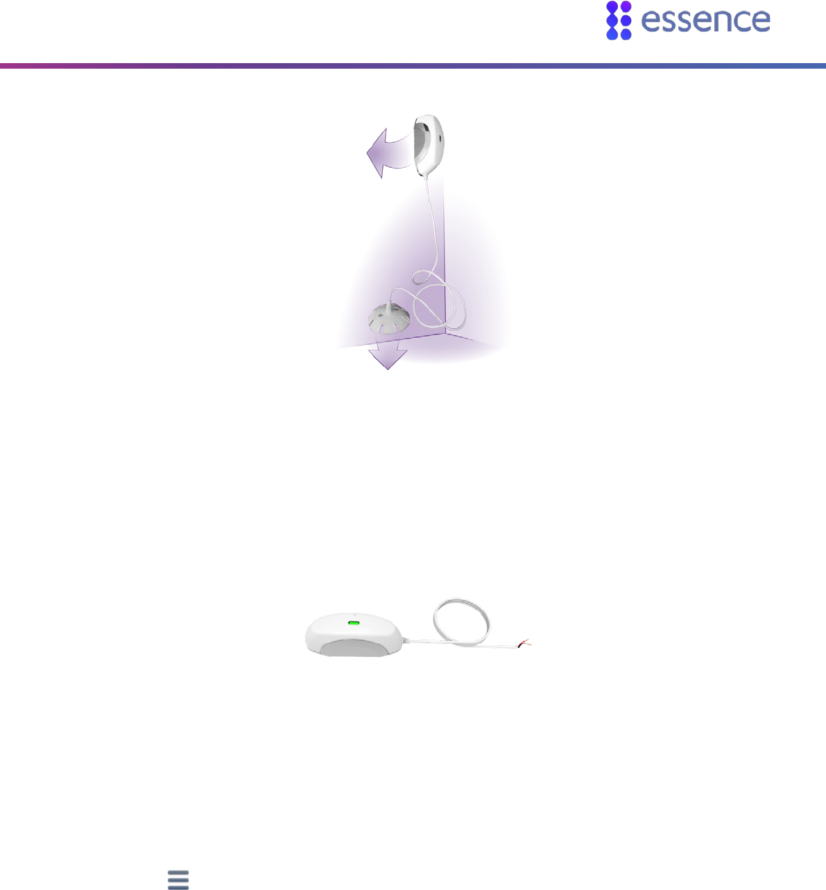
Installing WeR@Home™
WeR@Home™ Installation Guide 31
Figure 41: Example of Flood Detector Installation
2.5.7 Installing a Universal Transmitter
The universal transmitter enables you to detect changes in the state of third-party or legacy devices.
Figure 42: Universal Transmitter
To install the universal transmitter:
1. Choose an installation location. Find a flat, smooth, vertical surface at the location.
2. If the universal transmitter is included in the WeR@Home™ kit, skip to step 2l.
Otherwise, add the universal transmitter to WeR@Home™:
a. Open the WeR@Home™ app.
b. Tap . The main menu appears.
c. Tap DEVICES. The Devices screen appears.
d. Tap Add device. The Add New Devices screen appears.
e. Select Universal Transmitter. The Add UT Device screen appears.
Installing WeR@Home™
32 WeR@Home™ Installation Guide
f. Tap to select device type. The Select Device Type screen appears displaying a list of third-
party device types supported by WeR@Home™.
g. Tap the device type you want. The Add UT Device screen appears for the selected device type.
h. Set Wire state open:
the device circuit is open.
the device circuit is closed.
i. For a security device, set Report device status change:
report changes to the hub.
do not report changes to the hub.
j. Tap OK. The Universal Transmitter pairing screen appears as the device scan begins.
k. Place the transmitter close to the hub.
l. Release the transmitter from the mounting base by inserting and twisting a coin to separate
the cover from the base.
Figure 43: Releasing the Transmitter Base
m. Insert one AA alkaline battery, observing the correct polarity.
n. Insert the transmitter into the mounting base. If the universal transmitter is included in the
WeR@Home™ kit, skip to step 3.
When pairing is successful, a window appears prompting you to enter the device name.
o. Enter the device’s system name and/or location and tap OK. The universal transmitter appears
in the list on the Devices screen.
3. Clean and dry the mounting location surface.

Installing WeR@Home™
WeR@Home™ Installation Guide 33
4. Peel off the mounting-tape protective strips from the transmitter.
Figure 44: Mounting Tape Protective Strips
5. Press the transmitter into place.
6. Connect the Universal Transmitter with a third-party ON/OFF-type device, by connecting the
wires at the end of the cord. The red wire is positive (+) and the black wire is negative (-).
The device must have a +/- circuit such that:
When the circuit is closed, the device is ON.
When the circuit is open, the device is OFF.
2.5.8 Installing a Z-Wave Plus Extender
Z-Wave allows you to convert your home into a Smart Home by giving you the ability to control and
monitor your household devices. WeR@Home™ integrated with Z-Wave provides you with the tools to
remotely manage your devices using a mobile app.
Z-Wave is a wireless technology designed for home automation. The core of Z-Wave technology is
interoperability, enabling the incorporation of third-party devices with your WeR@Home™ network,
to enhance your Smart Home experience.
When you connect the Z-Wave Plus extender to your WeR@Home™ hub, your WeR@Home™ becomes
a Smart Home network that can support the following Z-Wave device types:
Door locks
Lock sensors
On/Off switches
Dimmers
Thermostats
Power strips
Multi-channel devices with endpoints for the supported Z-Wave devices
Multi-colored (RGBW) LED bulbs
Multi-input/ multi-output devices
Glass break detectors
Garage door controllers

Installing WeR@Home™
34 WeR@Home™ Installation Guide
For information about installing the Z-Wave Plus extender and WeR@Home™ working with Z-Wave,
refer to the ESUGSL015 WeR@Home™ Z-Wave User Guide.
2.5.9 Installing an HD Camera
You can integrate HD network cameras with your WeR@Home™.
For information about installing the HD camera, refer to the ESUGSL022 WeR@Home™ HD Camera
User Guide.
2.6. Installing a Smart Repeater
The WeR@Home™ Smart Repeater extends the range of your WeR@Home™ hub, to help you maximize
the coverage of your home by WeR@Home™. The repeater allows you to connect devices to
WeR@Home™ which could not otherwise connect to the hub. The repeater manages the peripheral
devices connected to it, acts as a gateway to the Essence Cloud, and communicates with the Essence
servers which provide data to the app.
You install a repeater by adding it to an existing WeR@Home™.
Installing the repeater involves:
Ensuring you have the supplied:
Backup battery
SIM-card
Choosing a suitable location
Setting up the repeater
NOTE: For information about installing the repeater, refer to Finding a Suitable
Location, Setting up the Repeater, and Adding Peripheral Devices to the
Repeater. For all other information about the repeater, refer to ESUGSL038
WeR@Home Smart Repeater User Guide.
2.6.1 Finding a Suitable Location
To choose a location for the repeater, consider the following:
Install on a flat surface
Installing WeR@Home™
WeR@Home™ Installation Guide 35
Choose a location with adequate cellular reception
It is recommended to position the repeater at least 1 m (3.3 ft.) away from the planned
location of the peripheral devices to be connected to the repeater.
2.6.2 Setting up the Repeater
NOTE: WeR@Home™ must be disarmed when you set up a repeater.
To set up the repeater:
1. Open the WeR@Home™ app.
2. Tap . The main menu appears.
3. Tap DEVICES. The Devices screen appears.
4. Tap Add device. The Add New Devices screen appears.
5. Select Repeater. The installation tutorial appears.
6. Follow the instructions in the tutorial:
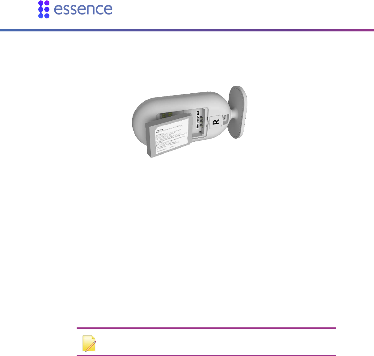
a. Remove the back cover from the repeater.
Figure 45: Remove Back Cover
b. Ensure the SIM-card is securely installed.
Installing WeR@Home™
36 WeR@Home™ Installation Guide
c. Insert the backup battery into the battery compartment, above the SIM-card, such that the
battery label faces upward and the battery contacts face the repeater’s base.
Figure 46: Insert Backup Battery
d. Return the back cover to the repeater.
e. Plug the power adapter cable into the mini-USB connector on the back of the repeater and the
power adapter cube into a power outlet. The LED on the front panel lights up red.
f. Wait for the LED on the front panel to light up green.
g. Take a note of the serial number on the bottom of the repeater.
7. In the app, tap Register now.
8. In the app, enter the serial number and tap Next. The server checks if the repeater and the hub are
using the same version of the software. If there is a difference, the server upgrades the lower
version to match the other, then updates the repeater's configuration.
9. Give the repeater a name, and the repeater is then added to the list of devices.
10. Put the repeater in its location. You can now add peripheral devices to the repeater.
NOTE: You can add up to two repeaters to each hub.
2.6.3 Adding Peripheral Devices to the Repeater
You can add up to 63 devices to a repeater.
Adding a new peripheral device to the repeater involves:
Adding each device to WeR@Home™ by pairing the device with the repeater
Installing the device in the chosen location

Installing WeR@Home™
WeR@Home™ Installation Guide 37
NOTE: You must connect the Z-Wave dongle, any Z-Wave or NEST devices, or
HD cameras, to a hub and not to a repeater.
Refer to Pairing a Device on page 50.Pairing a DevicePairing a Device
2.7. Testing the Signal Strength of Peripheral Devices
Once you have added a peripheral device to your WeR@Home™, you can test the signal strength.
NOTE: You cannot check the signal coverage for a tag or a remote control.
To test the signal strength:
1. Tap . The main menu appears.
2. Tap DEVICES. The Devices screen appears.
3. Tap the device whose signal strength you want to check. Device settings are displayed.
4. Tap Test Signal Strength, and follow the on-screen instructions. WeR@Home™ tests the signal
strength and displays the result as one of the following:
Red – signal strength is low. Find a location for the device with better signal coverage.
Orange – signal strength is acceptable. Consider finding a location for the device with better
signal coverage.
Green – signal strength is good.
Green with red exclamation mark – signal strength is good, but the device is too close to the
hub. Find a location for the device that is further away from the hub.

Setting-Up Your WeR@Home™
38 WeR@Home™ Installation Guide
3. Setting-Up Your WeR@Home™
To set up the way you use WeR@Home™, you can configure the following:
Customizing PIN protection
Arming and disarming WeR@Home™
Working with multiple places
Configuring devices
Managing users
Using Smart Rules
For detailed instructions, refer to ESUGSL018 WeR@Home™ User Guide.
Technical Specifications
WeR@Home™ Installation Guide 39
Technical Specifications
This section includes the following:
Hub (ES8000CP)
Remote Control (ES800KF)
Camera Detector (ES800IPD)
Motion Detector (ES800PIR)
Door/Window Sensor (ES800MGL)
Siren (ES800SRN)
Tag Reader (ES800TR)
Flood Detector (ES800FL)
Universal Transmitter (ES800UT)
Z-Wave Plus Extender (ES800ZWP)
Smart Repeater (ES800RP)
Maximum System Configuration per Hub
FCC and IC Safety Notice
NOTE: The full part number is required when ordering components. Contact
your Essence account manager or professional services personnel to receive the
part numbers.
Table 3: Hub (ES8000CP)
Category Specifications
Communications
Maximum RF range: 600 m (1,968 ft.) open air
ECOP bi-directional radio protocol
Modulation and frequency: DSSS, 2.4GHz
Maximum transmission: 25 mW (14 dBm)
Data security: 128-bit AES encryption
Cloud (internet):
LAN/Ethernet port: downlink 384 kBps, uplink 120 kBps
Optional 3G/4G(HSPA+) support (separate PN)

Technical Specifications
40 WeR@Home™ Installation Guide
Category Specifications
Power
100-240 V AC to 5 V DC power adapter/charger
3.7 V 1.4 Ah Li-polymer rechargeable backup battery
Maximum three hours battery life
Dimensions
Size (H x W x D): 141 x 75 x 41 mm (5.6 x 3 x 1.6 in.)
Weight: 125 g (0.28 lb.) + 35 g (0.08 lb.) backup battery
LAN cable: UTP unshielded twisted-pair cable, maximum length 3 m (10 ft.)
Environment
Storage ambient temperature range: -20oC to 60oC (-4oF to 140oF)
Operating ambient temperature range with battery: -5oC to 50oC (23oF to 122oF)
RF operating humidity: up to 95% non-condensing
Compliance
FCC: cellular/non-cellular versions - YXG-ES8000GP/Y4I-ES8000CP
IC: cellular version - 11061A-ES8000GP
NOTE: The FCC and IC Safety Notice applies to this device
Table 4: Remote Control (ES800KF)
Category Specifications
Communications Maximum RF range: 600 m (1,968 ft.) open air
ECOP bi-directional radio protocol
Modulation and frequency: DSSS, 2.4 GHz
Maximum transmission: 25 mW (14 dBm)
Data security: 128-bit AES encryption
Power One 3 V CR2450 lithium battery
Three-year battery life
Dimensions Size (H x W x D): 61 x 43 x 12 mm (2.4 x 1.7 x 0.5 in.)
Weight: 25 g (0.06 lb.) including the battery
Environment Storage ambient temperature range: -10°C to 55°C (14°F to 131°F)
Operating ambient temperature range with battery: -5°C to 55°C (23°F to 131°F)
RF operating humidity: up to 95% non-condensing
Compliance FCC: Y4I-M801EKFB
IC: 11061A-ES800KF
NOTE: The FCC and IC Safety Notice applies to this device

Technical Specifications
WeR@Home™ Installation Guide 41
Table 5: Camera Detector (ES800IPD)
Category Specifications
Communications
Maximum RF range: 500 m (1,640 ft.) open air
Maximum transmission: 25 mW (14 dBm)
ECOP bi-directional radio protocol
Modulation and frequency: DSSS, 2.4 GHz
Data security: 128-bit AES encryption
Security Tamper alarm: when unit is tilted
Detection range: up to 12 m (39.4 ft.)
Image Capture
Captures color motion: JPEG photos (up to 5 frames per second)
Supported video resolutions: 80 x 60 (QQQVGA) to 640 x 480 (VGA)
Illumination (at night or in low-light conditions) auto-activated super-bright white LED
Diagonal shooting angle: 90o
Special Features
4G DragonFlyEye™ lens technology for optional pet immunity
Optional up to 30 kg (66 lb.) pet immune lens
Temperature compensation for the motion detector element
Power Three AA size alkaline batteries
One-year battery life
Dimensions Size (H x W x D): 123 x 58 x 60 mm (4.8 x 2.4 x 2.4 in.)
Weight: 160 g (0.35 lb.) + 45 g (0.1 lb.) batteries
Environment
Storage ambient temperature range: -20°C to 50°C (-4°F to 122°F)
Operating ambient temperature range with batteries: 0°C to 50°C (32°F to 122°F)
RF operating humidity: up to 95% non-condensing
Compliance
FCC: Y4I-M800IPD
IC: 11061A-ES800IPD
NOTE: The FCC and IC Safety Notice applies to this device
Table 6: Motion Detector (ES800PIR)
Category Specifications
Communication Maximum RF range: 500 m (1,640 ft.) open air
Maximum transmission: 25 mW (14 dBm)
ECOP bi-directional radio protocol
Modulation and frequency: DSSS, 2.4 GHz
Data security: 128-bit AES encryption
Security Tamper alarm: when unit is tilted
Detection range: up to 12 m (39.4 ft.)
Power
Consumption
Two AA-size alkaline batteries
Three-year battery life

Technical Specifications
42 WeR@Home™ Installation Guide
Category Specifications
Special Features 4G DragonFlyEye™ lens technology for optimal pet immunity
Optional up to 30 kg (66 lb.) pet immune lens
Temperature compensation for the motion detector element
Dimensions Size (H x W X D): 114 x 60 x 50 mm (4.5 x 2.4 x 2.0 in.)
Weight: 90 g (0.2 lb.) + 30 g (0.07 lb.) batteries
Environment Storage ambient temperature range: -20°C to 50°C (-4°F to 122°F)
Operating ambient temperature range with batteries: 0°C to 50°C (32°F to 122°F)
RF operating humidity: up to 95% non-condensing
Compliance FCC: Y4I-M800PIR
IC: 11061A-ES800PIR
NOTE: The FCC and IC Safety Notice applies to this device
Table 7: Door/Window Sensor (ES800MGL)
Category Specifications
Communication Maximum RF range: 500 m (1,640 ft.) open air
Maximum transmission: 25 mW (14 dBm)
ECOP bi-directional radio protocol
Modulation and frequency: DSSS, 2.4 GHz
Data security: 128-bit AES encryption
Security Optional tamper mechanism with double trigger:
When the transmitter is removed from its mounting base
When the device is removed from its location
Power One AA size alkaline battery
Two-year battery life
Dimensions Transmitter
Size (H x W x D): 72 x 30 x 25 mm (2.8 x 1.2 x 1.0 in.)
Weight: 25 g (0.06 lb.) + 15 g (0.03 lb.) battery
Magnet
Size (H x W x D): 52 x 24 x 18 mm (2 x 0.9 x 0.7 in.)
Weight: 25 g (0.06 lb.)
Environment Storage ambient temperature range: -20°C to 50°C (-4°F to 122°F)
Operating ambient temperature range with battery: 0°C to 50°C (32°F to 122°F)
RF operating humidity: up to 95% non-condensing
Compliance FCC: YXG-ES800MGL
IC: 11061A-ES800MGLI
NOTE: The FCC and IC Safety Notice applies to this device

Technical Specifications
WeR@Home™ Installation Guide 43
Table 8: Siren (ES800SRN)
Category Specifications
Communications Maximum RF range: 500 m (1,640 ft.) open air
Maximum transmission: 25 mW (14 dBm)
ECOP bi-directional radio protocol
Modulation and frequency: DSSS, 2.4 GHz
Data security: 128-bit AES encryption
Security Tamper Alarm: when removed from mounting base
Power Four AA-size alkaline batteries
Two-year battery life
Dimensions Size (H x W x D): 120 x 120 x 39 mm (4.7 x 4.7 x 1.5 in.)
Weight: 150 g (0.33 lb.) + 100 g (0.22 lb.) batteries
Environment Storage ambient temperature range: -20°C to 50°C (-4°F to 122°F)
Operating ambient temperature range with batteries: 0°C to 50°C (32°F to 122°F)
RF operating humidity: up to 95% non-condensing
Compliance FCC: Y4I-M800SRN
IC: 11061A-ES800SRN
NOTE: The FCC and IC Safety Notice applies to this device
Table 9: Tag Reader (ES800TR)
Category Specifications
Communications Maximum RF range: 500 m (1,640 ft.) open air
Maximum transmission: 25 mW (14 dBm)
ECOP bi-directional radio protocol
Modulation and frequency: DSSS, 2.4 GHz
RFID band: ISO 14443a/MiFare, 106 kbps, 13.56 MHz
Data security: 128-bit AES encryption
Security Tamper alarm: when detached from wall
Support for up to 8 tags
Power Three AA size alkaline batteries (reader only)
One-year battery life
Dimensions Reader
Size (H x W x D): 98 x 98 x 28 mm (3.9 x 3.9 x 1.0 in.)
Weight: 135 g (0.3 lb.) + 45 g (0.1 lb.) batteries
Tag
Size (H x W x D): 47 x 33 x 10 mm (1.9 x 1.3 x 0.4 in.)
Weight: 10 g (0.02 lb.)

Technical Specifications
44 WeR@Home™ Installation Guide
Category Specifications
Environment Storage ambient temperature range: -20°C to 50°C (-4°F to 122°F)
Operating ambient temperature range with battery: 0°C to 50°C (32°F to 122°F)
RF operating humidity: up to 95% non-condensing
Compliance FCC: YXG-ES800TR5
IC: 11061A-ES800TR5
NOTE: The FCC and IC Safety Notice applies to this device
Table 10: Flood Detector (ES800FL)
Category Specifications
Communications Maximum RF range: 500 m (1,640 ft.) open air
ECOP bi-directional radio protocol
Modulation and frequency: DSSS, 2.4 GHz
Data security: 128-bit AES encryption
Power One AA size alkaline battery
Two-year battery life
Dimensions Transmitter
Size (H x W x D): 72 x 25 x 30 mm (2.8 x 1.0 x 1.2 in.)
Weight: 25 g (0.06 lb.) + 15 g (0.03 lb.) battery
Sensor
Size (H x W x D): 50 x 50 x 22 mm (2 x 2 x 0.9 in.)
Weight: 25 g (0.06 lb.)
Cable length: 30 cm (11.8 in.)
Environment Storage ambient temperature range: -20°C to 50°C (-4°F to 122°F)
Operating ambient temperature range with battery: 0°C to 50°C (32°F to 122°F)
RF operating humidity: up to 95% non-condensing
Compliance FCC: YXG-ES800FL
IC: 11061A-ES800FL
NOTE: The FCC and IC Safety Notice applies to this device

Technical Specifications
WeR@Home™ Installation Guide 45
Table 11: Universal Transmitter (ES800UT)
Category Specifications
Communications Maximum RF range: 500 m (1,640 ft.) open air
ECOP bi-directional radio protocol
Modulation and frequency: DSSS, 2.4 GHz
Data security: 128-bit AES encryption
Power One AA size alkaline battery
Two-year battery life
Dimensions Size (H x W x D): 72 x 30 x 25 mm (2.8 x 1.2 x 1.0 in.)
Weight: 25 g (0.06 lb.) + 15 g (0.03 lb.) battery
Cable length: 30 cm (11.8in.)
Environment Storage ambient temperature range: -20°C to 50°C (-4°F to 122°F)
Operating ambient temperature range with battery: 0°C to 50°C (32°F to 122°F)
Humidity: up to 95% non-condensing
Compliance FCC: YXG-ES800UT
IC: 11061A-ES800UT
NOTE: The FCC and IC Safety Notice applies to this device
Table 12: Z-Wave Plus Extender (ES800ZWP)
Category Specifications
Technology Uses the Z-Wave® 500-series chip
Supported Z-Wave
Device Types Binary switches (For example, ON/OFF devices)
Multi-level switches (For example, dimmers)
Thermostats
Door locks
Multi-channel devices (For example, power strips)
RGBW LED bulbs
Controller Capacity The maximum capacity for a single Z-Wave Plus Extender is up to 232 Z-Wave devices.

Technical Specifications
46 WeR@Home™ Installation Guide
Category Specifications
Communications Maximum RF range: 30 m (98 ft.) open air
Z-Wave bi-directional radio protocol (onboard)
Modulation and frequency: GFSK Modulation
868.4 MHz (Europe)
908.4 MHz (USA, Canada, Mexico)
921.4 MHz (Australia)
869 MHz (Russia)
926.3 MHz (Japan)
916 MHz (Israel)
Bit Rate: up to 100 kBps
Security Data security: 128-bit AES encryption
Unique electronic serial number
Power
Powered only by the hub’s power adapter
Note: In the event of a power outage, the Z-Wave Plus Extender is not powered by the hub’s
backup battery
Dimensions
Size (H x L x D): 5 x 58 x 24 mm (0.2 x 2.3 x 0.9 in.)
Weight: 10 g (0.03 lb.)
Cable length: 15 cm (5.9 in.)
Environment
Storage ambient temperature range: -20°C to 50°C (-4°F to 122°F)
Operating ambient temperature range with battery: 0°C to 50°C (32°F to 122°F)
RF operating humidity: up to 95% non-condensing
Compliance
FCC: YXG-ES800ZWP
IC: 11061A-ES800ZWP
NOTE: The FCC and IC Safety Notice applies to this device
CE: Safety: EN 60950-1; Radio: EN 300 220-2; EMC EN 301 489-1;
EN 301 489-3
Z-Wave Plus certification
Table 13: Smart Repeater (ES800RP)
Category Specifications
Communications
Maximum RF range: 600 m (1,968 ft.) open air
ECOP bi-directional radio protocol
Modulation and frequency: DSSS, 2.4 GHz
Maximum transmission: 25 mW (14 dBm)
Data security: 128 bit AES encryption
Cloud (internet): 3G/4G (HSPA+)

Technical Specifications
WeR@Home™ Installation Guide 47
Category Specifications
Power
100-240 V AC to 5 V DC power adapter/charger
3.7 V 1.4 Ah Li-polymer rechargeable backup battery
Maximum three hours battery life
Dimensions Size (H x W x D): 141 x 75 x 41 mm (5.6 x 3 x 1.6 in.)
Weight: 125 g (0.27 lb.) + 35 g (0.08 lb.) backup battery
Environment
Storage ambient temperature range: -20oC to 60oC (-4oF to 140oF)
Operating ambient temperature range with battery: -5oC to 50oC (23oF to 122oF)
RF operating humidity: up to 95% non-condensing
Compliance
FCC: Y4I- ES8000CP, YXG-ES8000GP
IC: 11061A-ES8000GP
NOTE: The FCC and IC Safety Notice applies to this device
CE – EMC:
ETSI EN 301 489-1 V1.9.2
ETSI EN 301 489-3 V1.6.1
EN 61000-6-3: 2007/A1: 2011
CE – Radio:
ETSI EN 300 220-1 V3.1.1: 2017
ETSI EN 300 220-2 V3.1.1:2017
CE – Safety:
EN 60950-1: 2006/A11: 2009/A1: 2010/A12: 2011/A2: 2013

Technical Specifications
48 WeR@Home™ Installation Guide
Table 14: Maximum System Configuration per Hub
Device or Group Maximum Maximum Within Group
Total Devices 91
Security Group 64 Camera Detector 8
Motion Detector 64
Door/Window Sensor 64
Tag Reader 8 with 8 tags
Universal Transmitter 64
Safety Group 16 Smoke Alarm 16
Flood detector 16
Universal Transmitter 16
Siren 3
Remote Control 8
Smart Repeaters* 2
Z-Wave Plus Extender 1 for up to 232 Z-Wave devices
HD Camera Depends on the service package
*You can add up to 63 devices to a repeater.
FCC and IC Safety Notice
This device complies with Part 15 of the FCC Rules.
Operation is subject to the following two conditions:
1. This device may not cause harmful interference, and
2. This device must accept any interference received, including interference that may cause
undesired operation.
Le présent appareil est conforme aux CNR d’Industrie Canada applicables aux appareils radio exempts
de licence. L’exploitation est autorisée aux deux conditions suivantes:
1. l’appareil ne doit pas produire de brouillage;
2. l’utilisateur de l’appareil doit accepter tout brouillage radioélectrique subi, même si le brouillage
est susceptible d’en compromettre le fonctionnement.

Technical Specifications
WeR@Home™ Installation Guide 49
Changes or modifications to this equipment not expressly approved by the party responsible for
compliance (Essence Security International Ltd.) could void the user’s authority to operate the
equipment.
WARNING! To comply with FCC and IC RF exposure compliance requirements, the device should be
located at a distance of at least 20 cm from all persons during normal operation. The antennas used for
this product must not be co-located or operated in conjunction with any other antenna or
transmitter.
Le dispositif doit être placé à une distance d'au moins 20 cm à partir de toutes les personnes au cours
de son fonctionnement normal. Les antennes utilisées pour ce produit ne doivent pas être situés ou
exploités conjointement avec une autre antenne ou transmetteur.
NOTE: This equipment has been tested and found to comply with the limits for a Class B digital device,
pursuant to Part 15 of the FCC Rules. These limits are designed to provide reasonable protection
against harmful interference in a residential installation. This equipment generates, uses and can
radiate radio frequency energy and, if not installed and used in accordance with the instructions, may
cause harmful interference to radio communications. However, there is no guarantee that
interference will not occur in a particular installation. If this equipment does cause harmful
interference to radio or television reception, which can be determined by turning the equipment off
and on, the user is encouraged to try to correct the interference by one or more of the following
measures:
• Reorient or relocate the receiving antenna.
• Increase the separation between the equipment and receiver.
• Connect the equipment into an outlet on a circuit different from that to which the receiver is
connected.
• Consult the dealer or an experienced radio/TV technician for help.
This Class B digital apparatus complies with Canadian ICES-003.
Cet appareil numerique de la classe B est conforme a la norme NMB-003 du Canada.

Pairing a Device
50 WeR@Home™ Installation Guide
Pairing a Device
To pair a device:
1. Tap . The main menu appears.
2. Tap DEVICES. The Devices screen appears.
3. Tap Add device. The Add New Devices screen appears displaying a list of the available device
types.
4. Select a device type. The Connect to screen appears displaying the hub and repeaters.
NOTE: If you select a device which must be connected to the hub, the Connect
to screen is not displayed, and instead the Pairing screen appears.
5. Tap the hub or the repeater you want to add the device to. The Pairing screen appears and
WeR@Home™ scans for the device.
6. Place the device close to the hub or smart repeater.
7. If the device has a tamper switch, activate the tamper.
8. Insert the batteries.
9. When prompted by the app, enter the device’s system name and/or location and other device
attributes.
10. Tap OK.
The WeR@Home™ Kit
WeR@Home™ Installation Guide 51
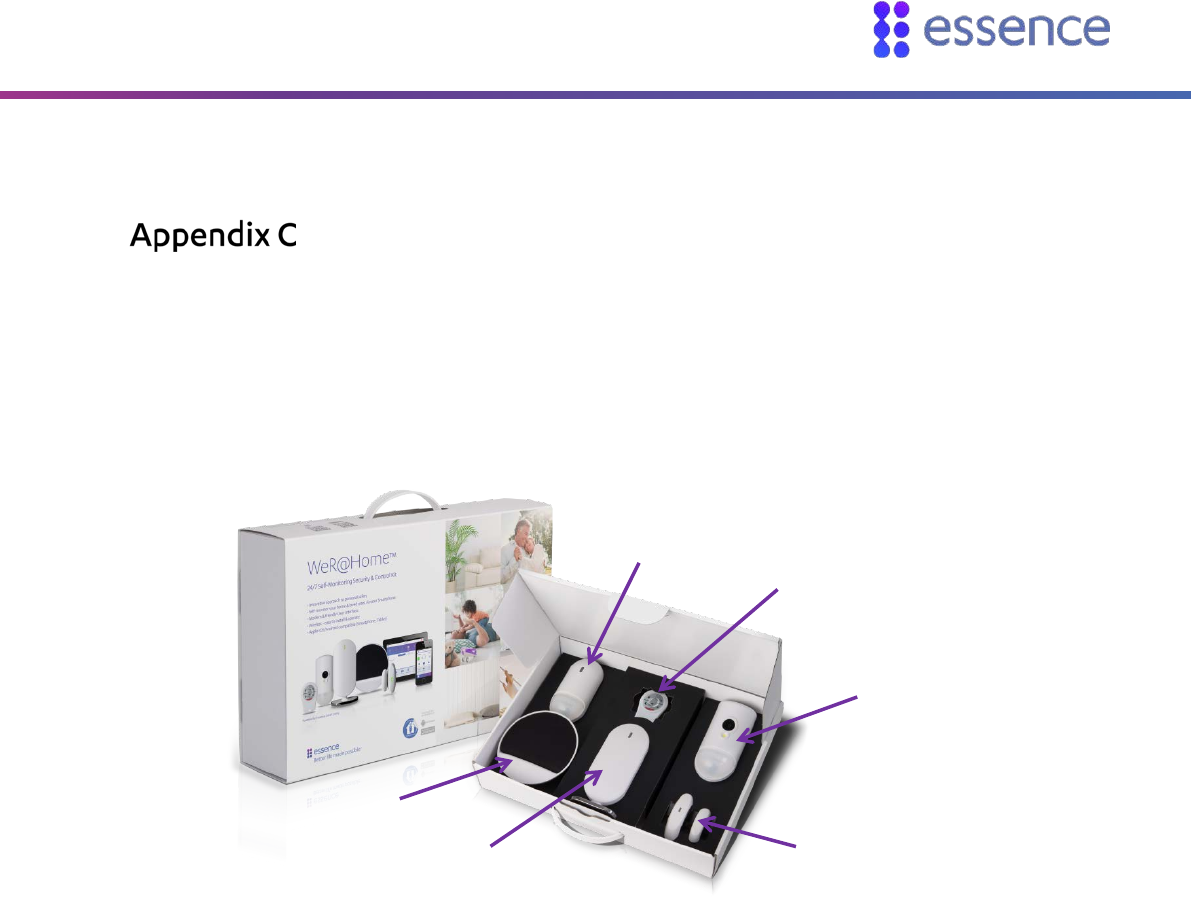
The WeR@Home™ Kit
WeR@Home™ products are usually sold as boxed kits which include a predefined set of devices similar
to the one shown in Figure 47. The components included in the kit, except for the remote control, are
pre-paired with the hub in the kit. The remote control is not pre-paired because the device must be
assigned to a specific user.
Figure 47: A Sample WeR@Home™ Kit
Siren
WeR@Home™ Hub
Motion Detector
Remote Control
Camera
Detector
Door/Window
Sensor
Installing with Screws
52 WeR@Home™ Installation Guide
Installing with Screws
As an option, you can install WeR@Home™ devices with screws.
Installing with screws:
Allows more flexibility in choosing installation locations
Provides support when installing at a difficult angle
Can reinforce the tape installation
Prepare the following equipment:
A drill with an appropriate bit
A Philips screwdriver
3 x 35 DIN 7982 C screws and wall anchors. The number of the screws and wall anchors is
determined by the device being installed. Screws and wall anchors are not provided.
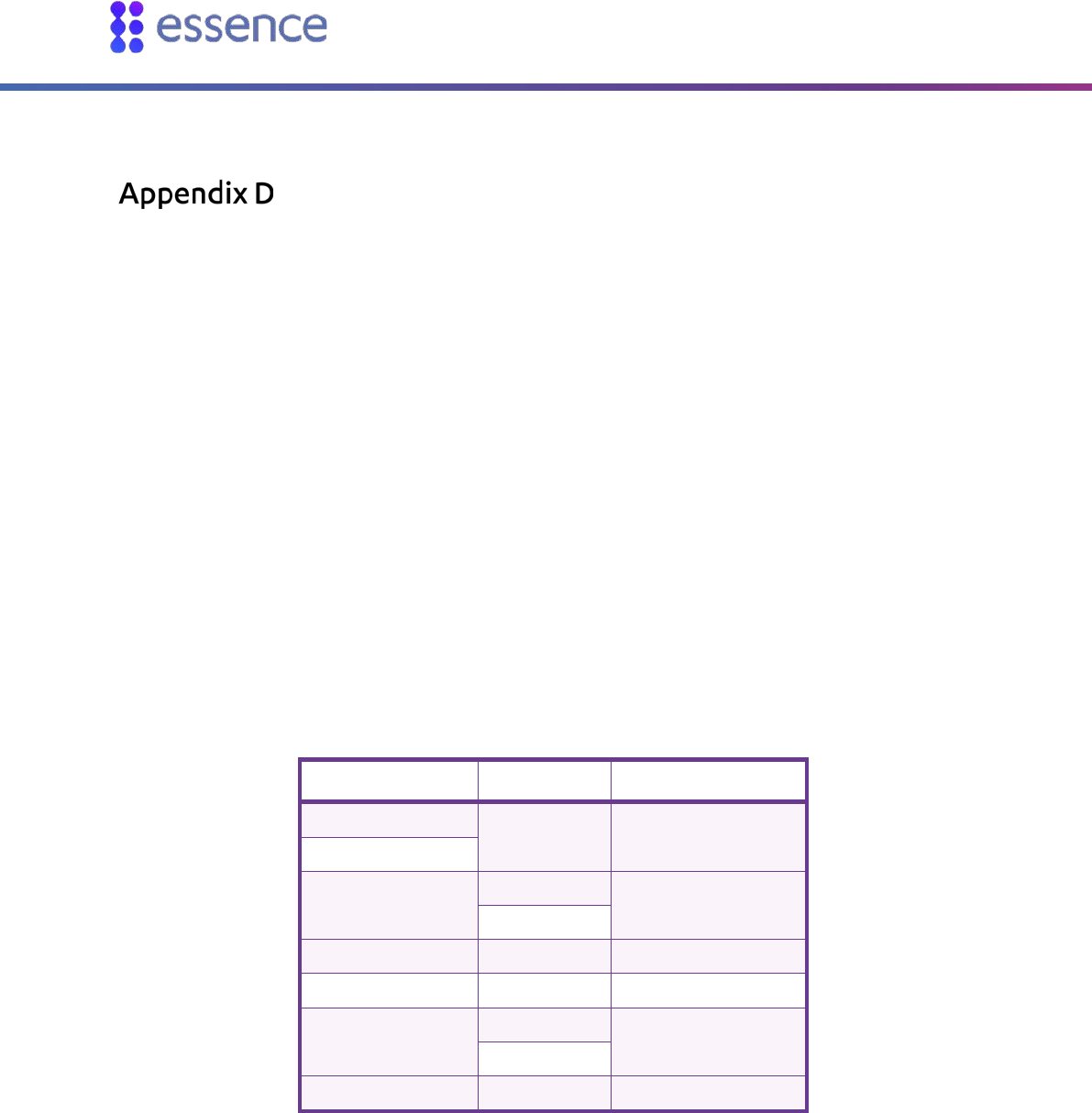
The table below is a summary of Essence recommendations regarding screws and wall anchors.
Table 15: Screws and Wall Anchors
Device Components Quantity per Device
Camera Detector 2-6
Motion Detector
Door/Window Sensor Transmitter 2
Magnet
Siren 3
Tag Reader 4
Flood Detector Transmitter 2
Sensor
Universal Transmitter Transmitter 2
The following are instructions for installing with screws by device type.
Installing with Screws
WeR@Home™ Installation Guide 53
Motion and Camera Detectors
The mounting-base has eight holes to allow for installation flexibility. Varying combinations of holes
allows you to install the camera or motion detector:
Flat on a wall
On an angle facing to the right
On an angle facing to the left
In a corner
The thin plastic covering over the holes can be removed, if necessary. All the corner support holes are
blocked by the mounting-tape. You can drill through the tape, if needed.
To install the motion or camera detector using screws:
1. Release the mounting-base by lifting the tab and pushing it forward.
Figure 48: Release Mounting-Base
Installing with Screws
54 WeR@Home™ Installation Guide
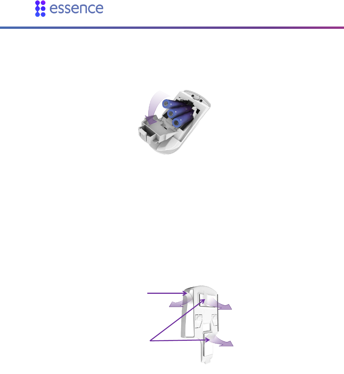
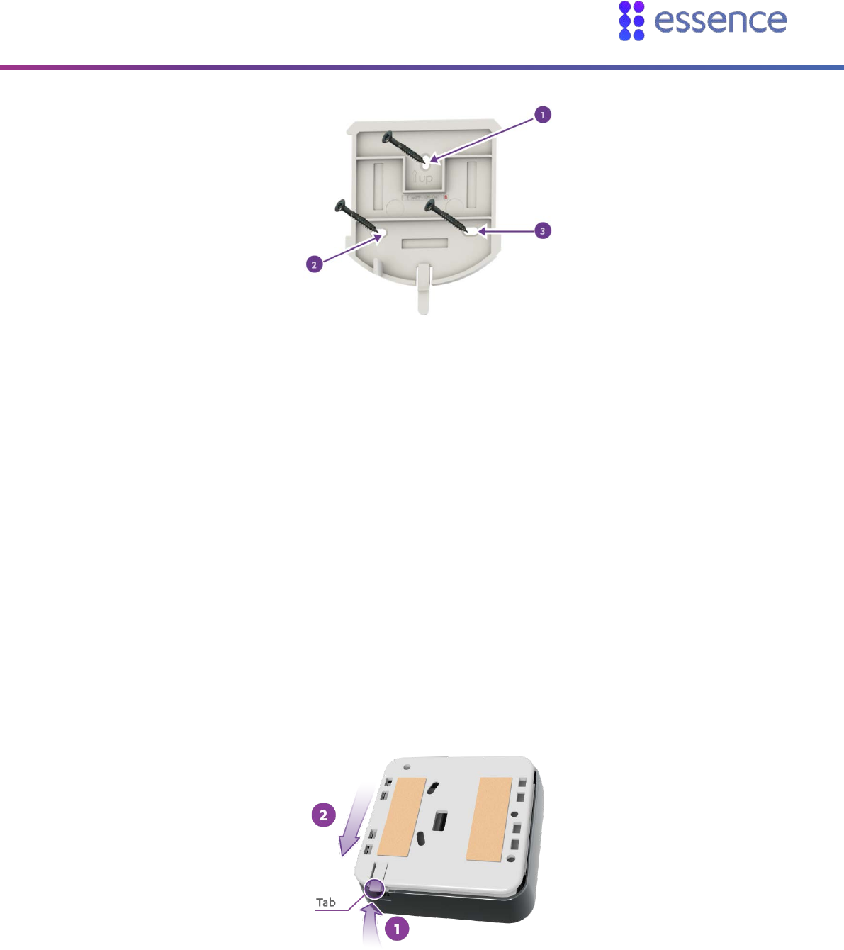
2. For wall mounting:
a. Remove the punch-outs 1 and 2 using a flat screwdriver.
Figure 49: Mounting-Base Screw Punch-outs
b. Place and hold the base on the desired mounting location and mark the drilling spots.
c. Drill the holes.
d. Insert the wall anchors, if needed.
e. Place the base over the wall anchors and screw in the screws.
3. For corner mounting, repeat the above procedure for punch-outs 3 through 8, using six screws
and six wall anchors.
3
4
5
8
7
6
2
1
Installing with Screws
WeR@Home™ Installation Guide 55
Door/Window Sensor, Flood Detector, or Universal Transmitter
For the Door/Window Sensor, you can install the transmitter using screws. The magnet is installed
only using mounting tape. You can also install the flood sensor using screws.
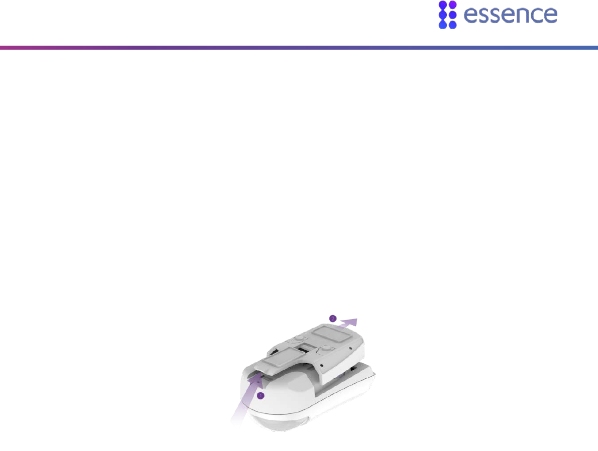
To install the transmitter using screws:
1. Insert a coin into one of the edge slots of the transmitter and twist the coin to release the
mounting base cover.
Figure 50: Releasing the Transmitter Base
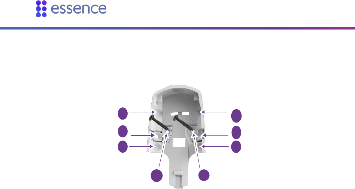
2. Remove punch-outs 1 and 2 using a flat screwdriver.
Figure 51: Transmitter Mounting with Screws
3. Place and hold the base on the desired mounting location.
4. Mark the drilling locations of the punch-outs 1 and 2.
5. Drill the holes.
6. Insert the wall anchors, if needed.
7. Place the base over the wall anchors.
8. Screw in the screws.
9. Attach the mounting base cover onto its base.
Installing with Screws
56 WeR@Home™ Installation Guide
To install the flood sensor using screws, position the sensor in the desired location and perform steps
4 through 8 of the transmitter installation procedure.
Figure 52: Mounting the Sensor Base with Screws
Siren
The mounting base has three holes for installation using screws.
To install the siren using screws:
1. Release the siren mounting base by lifting the tab and sliding the base in the tab’s direction.
Figure 53: Releasing the Siren Mounting Base
2. Remove the punch-outs using a flat screwdriver.
3. Place and hold the base on the desired mounting location.
Installing with Screws
WeR@Home™ Installation Guide 57
Figure 54: Siren Mounting Base with Screws
4. Mark the drilling locations for the punch-outs.
5. Drill the holes.
6. Insert the wall anchors if needed.
7. Place the base over the wall anchors.
8. Screw in the screws.
9. Slide the siren back into its mounting base.
Tag Reader
The tag reader mounting base has three holes for installation using screws.
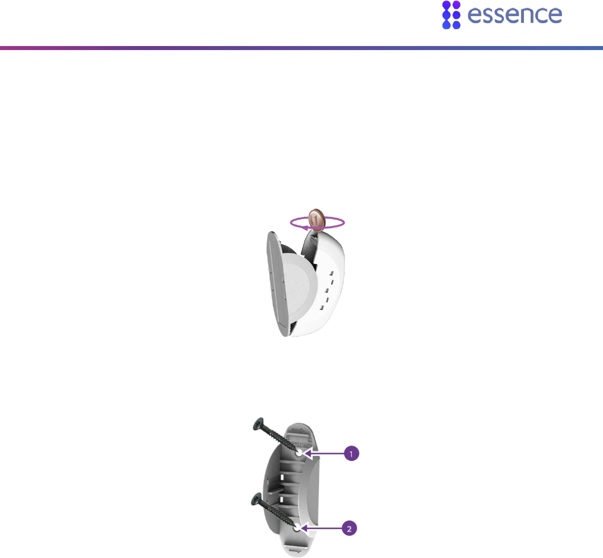
To install the tag reader using screws:
1. Release the tag reader mounting base by lifting the tab and sliding the base in the tab’s direction.
Figure 55: Releasing the Tag Reader Mounting Base
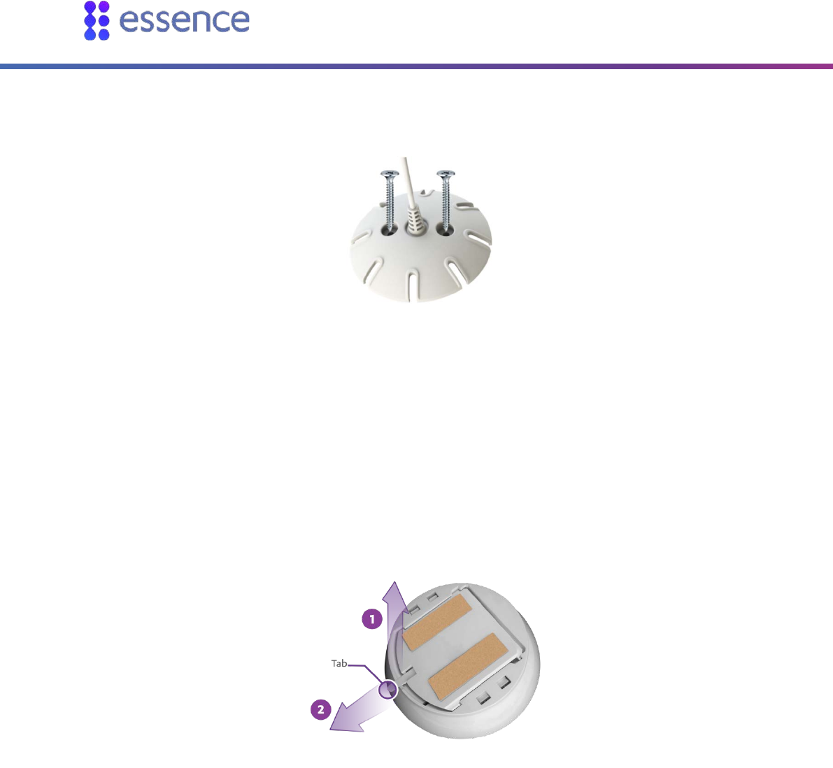
2. Place and hold the base on the desired mounting location.

Installing with Screws
58 WeR@Home™ Installation Guide
Figure 56: Tag Reader Mounting Base with Screws
3. Mark the drilling locations according to the specific holes.
4. Drill the holes.
5. Insert the wall anchors, if needed.
6. Place the base over the wall anchors.
7. Screw in the screws.
8. Insert the tag reader into its mounting base.
Installing a Pet Immune Lens
WeR@Home™ Installation Guide 59
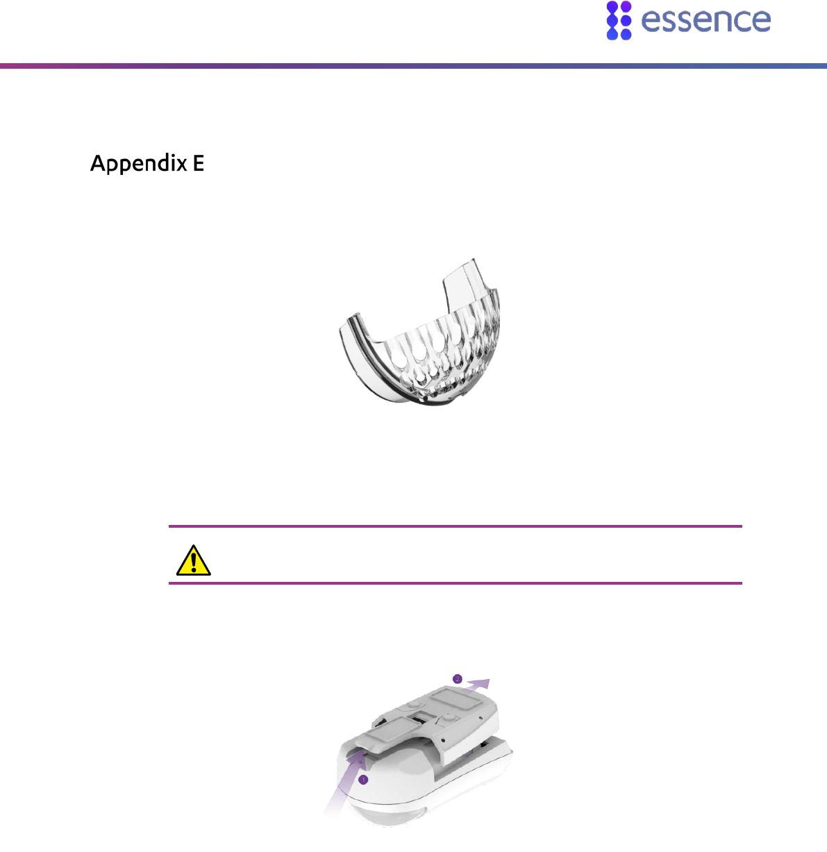
Installing a Pet Immune Lens
If you have a pet, use a pet immune lens to avoid your pet triggering alarms. The pet immune lens
reduces false detections by suppressing detections of small moving objects such as pets.
Figure 57: The Pet Immune Lens
To install the pet immune lens in the motion or camera detectors:
Caution: Perform this procedure with special care since the top part of the front
panel is breakable.
1. Release the device from the mounting base.
Figure 58: Releasing the Mounting Base
2. For the camera detector:
Unscrew the two screws above the battery compartment at the top of the back cover.
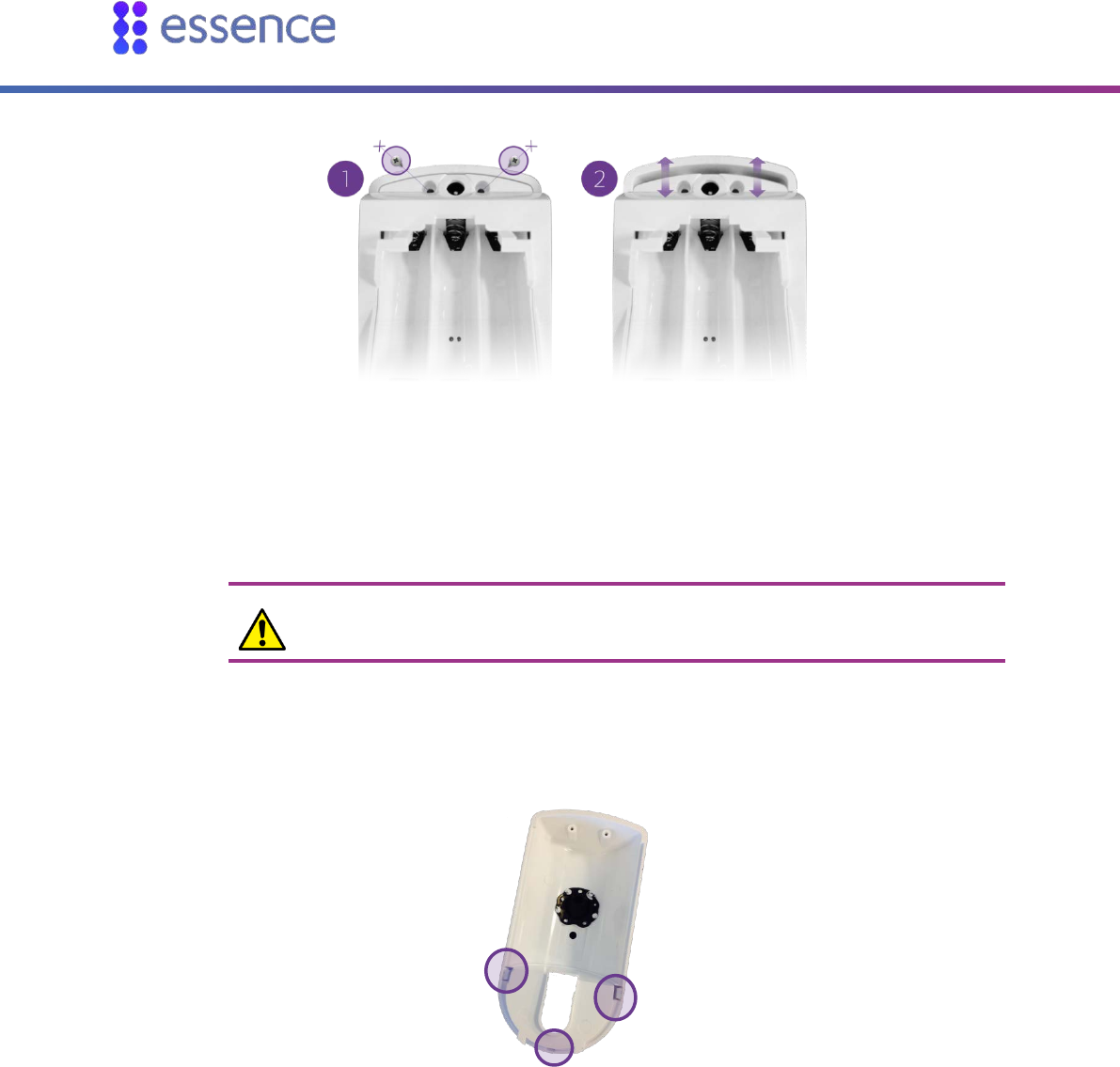
Installing a Pet Immune Lens
60 WeR@Home™ Installation Guide
Figure 59: Unscrew the Screws
Detach the back cover from the front panel. The circuit board is attached to the inner
compartment of the camera detector back cover.
Caution: When working within the inner compartment of the camera detector,
be careful not to damage the circuit board and other parts of the device.
3. Use a flat screwdriver to release the three latch tabs.
Figure 60: Lens Latch Tabs
The lens falls free of the panel. If the lens is not released, insert a dull, thin object through the
oval opening and gently push the lens.
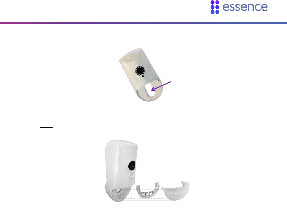
Installing a Pet Immune Lens
WeR@Home™ Installation Guide 61
Figure 61: Front Panel Oval Opening
4. Insert the pet immune lens into the lens opening in the front panel. The pet immune lens fits
inside the lens opening.
Figure 62: Assembling the Pet Immune Lens
5. Insert the lens in the groove surrounding the lens opening, placing the lens on top of the pet
immune lens.
6. Insert the latch tabs at the bottom center and at the side of the lens into the latch tab slots on the
lens opening. Figure 63 illustrates where and how to install the lens.
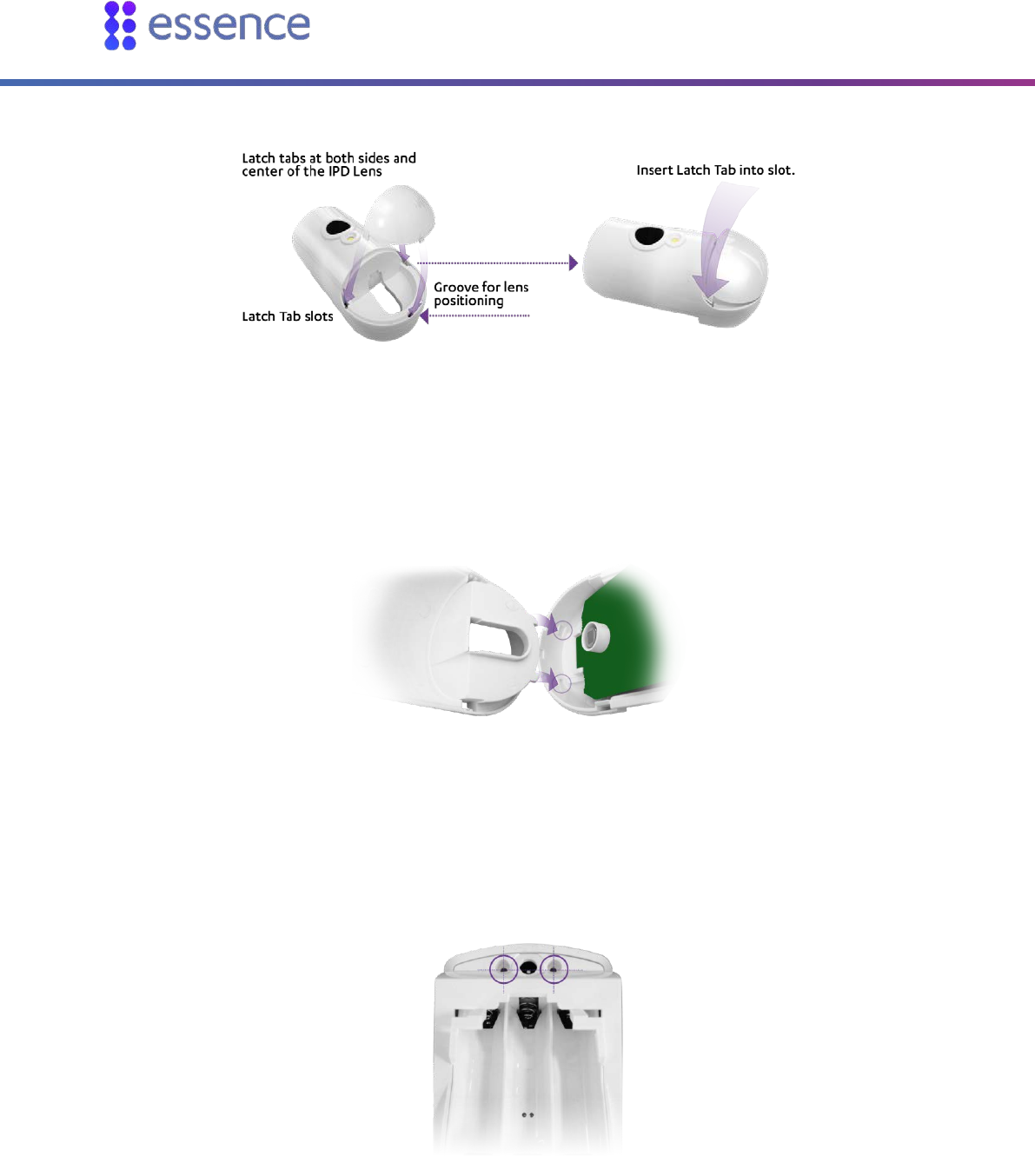
Installing a Pet Immune Lens
62 WeR@Home™ Installation Guide
Figure 63: Lens Tabs for Lens Insertion
The side and center latch tabs hold both lenses in place.
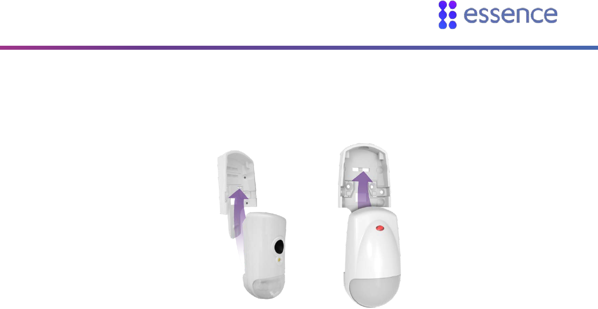
7. Insert the tabs, at the bottom end of the front panel, into the inner square slots, at the bottom end
of the back cover, as illustrated in Figure 64.
Figure 64: Align and Insert Tabs in Square Slots
8. For the camera detector:
a. Position the top of the back cover onto the top of the front cover, while aligning the holes for
the screws.
Figure 65: Align Holes for Screws
b. Attach the front panel to the back cover using the two screws.
Installing a Pet Immune Lens
WeR@Home™ Installation Guide 63
9. Insert the batteries.
10. Return the device onto the mounting-base such that the lens is facing downward.
Figure 66: Insert Device with the Lens Facing Downward

Battery Information
64 WeR@Home™ Installation Guide
Battery Information
Only batteries thoroughly tested and approved by Essence should be used to meet the device’s
specifications. The following battery manufacturers are approved by Essence:
GP
Energizer
Duracell
To comply with the UL certification standards, use GP International Limited batteries.
The table below defines the battery specifications and quantities for WeR@Home™ devices.
Table 16: Battery Quantities and Specifications
Device Quantity Type Voltage Chemistry Maximum Battery Life
Remote Control 1 CR2450 3V Lithium 3 years
Siren 4 AA 1.5V Alkaline 2 years
Motion Detector 2 AA 1.5V Alkaline 3 years
Camera Detector 3 AA 1.5V Alkaline 1 year
Door/Window Sensor 1 AA 1.5V Alkaline 2 years
Tag Reader 3 AA 1.5V Alkaline 1 year
Smoke Alarm 2 AA 1.5V Alkaline 2 years
Flood Detector 1 AA 1.5V Alkaline 2 years
Universal Transmitter 1 AA 1.5V Alkaline 2 years
NOTE: The battery images included in this guide are for illustration purposes
only.

Legal Notice
WeR@Home™ Installation Guide 65
Legal Notice
Usage of this document, and all information (including product information) provided within, are subject to the following terms and conditions, and all
applicable laws. If you do not agree with these terms, please do not access or use the remainder of this document.
This document contains highly confidential information, which is proprietary to Essence Security International (E.S.I.) Ltd. and/or its affiliates (hereafter,
"Essence"). No part of this document's contents may be used, copied, disclosed or conveyed to any third party in any manner whatsoever without prior
written permission from Essence.
The information included in this document is intended for your knowledge and for negotiation purposes only. Essence makes no implicit representations
or warranties with respect to such information.
The information included in this document is subject to change without notice. Any decision to rely on the information contained herein shall be at your
sole responsibility, and Essence will not accept any liability for your decision to use any information or for any damages resulting therefrom.
Certain laws do not allow limitations on implied warranties or the exclusion or limitation of certain damages. If these laws apply to you, some or all of the
above disclaimers, exclusions, or limitations may not apply to you.
By using the information contained herein, you agree that the laws of the State of Israel, without regard to principles of conflict of laws, will govern any
dispute of any sort that might arise between you and Essence regarding the information contained herein, and any such dispute shall be settled
exclusively in the competent courts of Tel Aviv-Jaffa, Israel.
All registered or unregistered trademarks, product names, logos and other service marks mentioned within this document are the property of Essence,
or their respective owners. Nothing contained herein shall be construed as conferring by implication, estoppels, or otherwise any license or right, either
express or implied, under any patent or trademark of Essence or any third party. No use of any trademark may be made without the prior written
authorization of Essence.
This document and all of its contents are protected intellectual property of Essence. Any copying, reprinting, reuse, reproduction, adaptation,
distribution or translation without the prior written permission of Essence is prohibited.
Please check your End User License Agreement (EULA) for terms and conditions.
© 2018 All rights reserved to Essence Security International (E.S.I.) Ltd.
For more information, please contact: Essence Security International (E.S.I.) Ltd.
12 Abba Eban Avenue,
Ackerstein Towers Bldg. D
Herzliya Pituach, 4612001 Israel
www.essence-grp.com
Tel: +972-73-2447777
Fax: +972-9-7729962