Essence Security ES800UT Universal transmitter User Manual We R System
Essence Security International ltd. Universal transmitter We R System
Contents
- 1. User_Guide_part1
- 2. User_Guide_part2
- 3. User_Guide_part3
- 4. User_Guide_part7
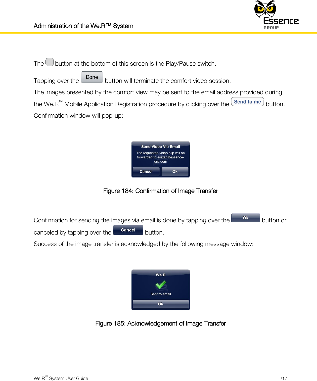
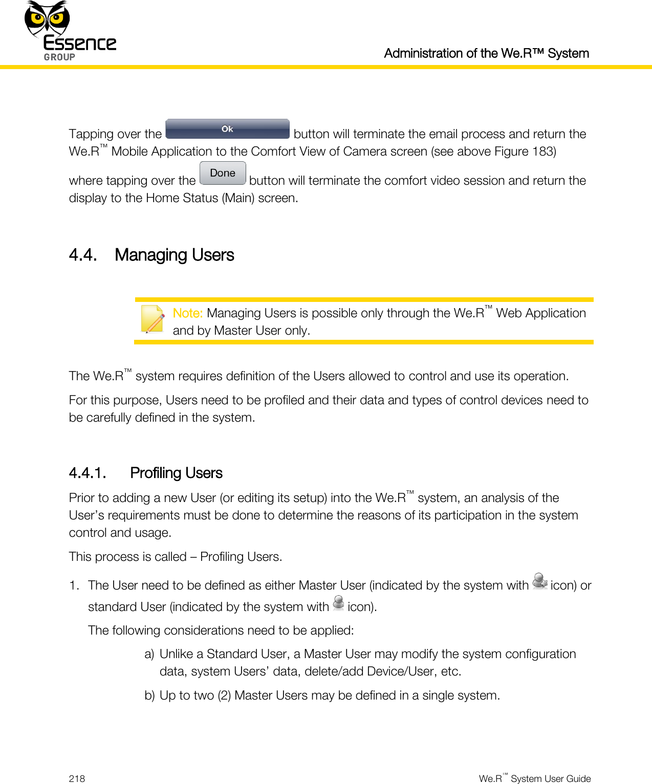
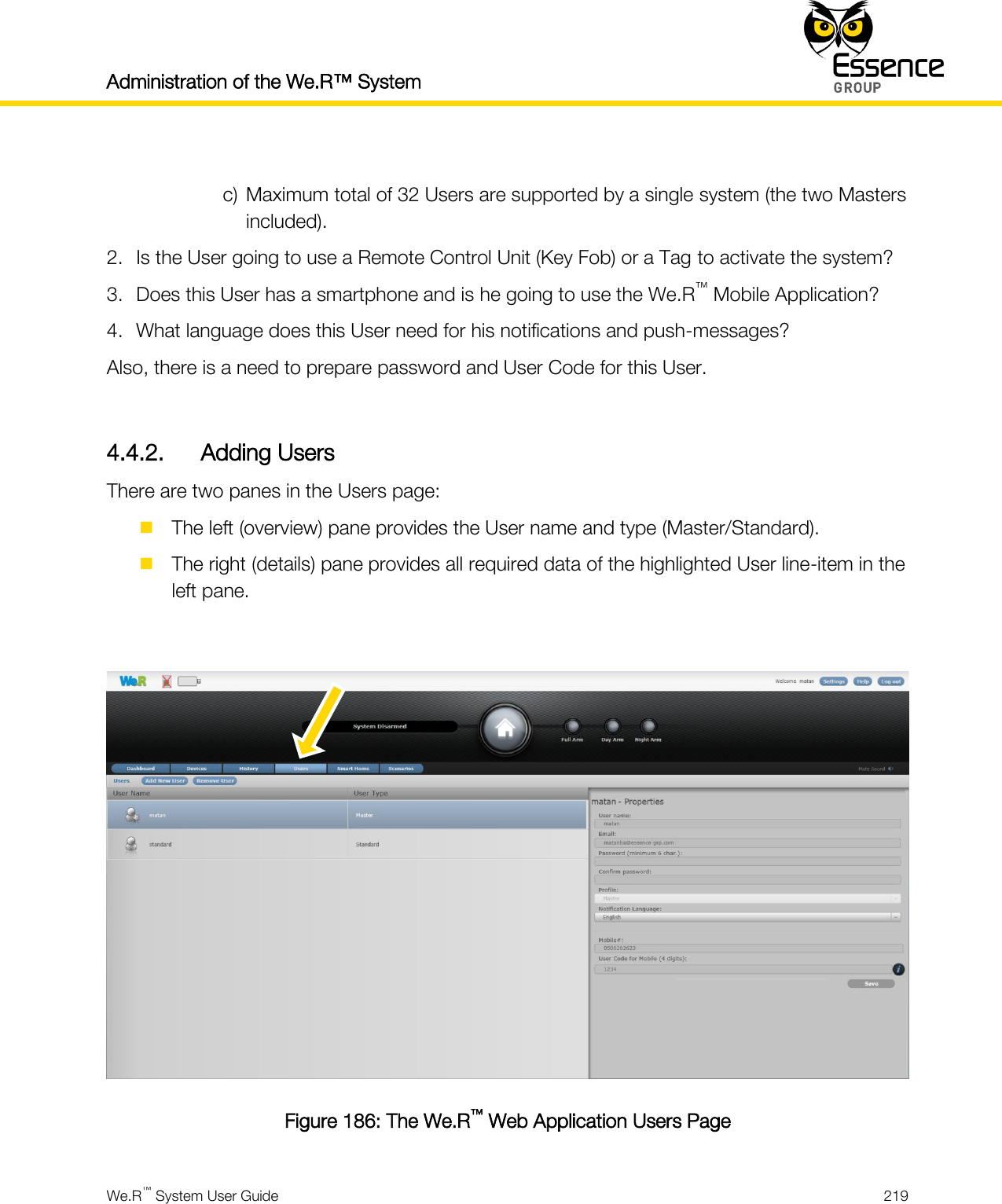
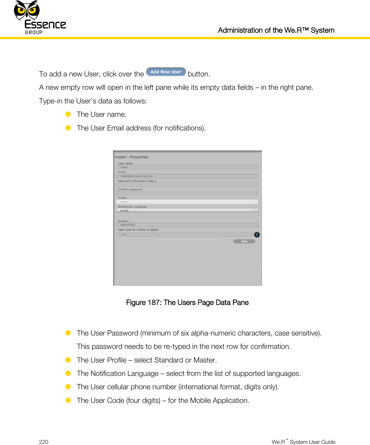
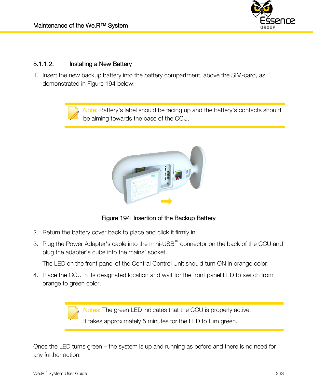
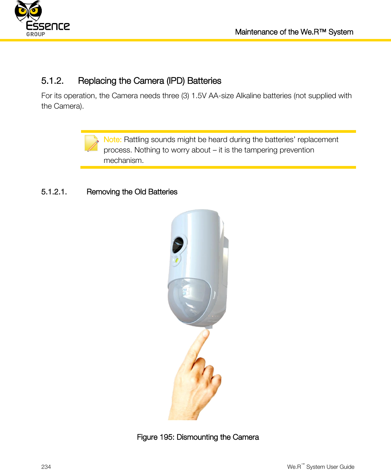
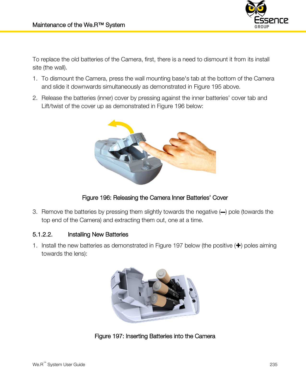
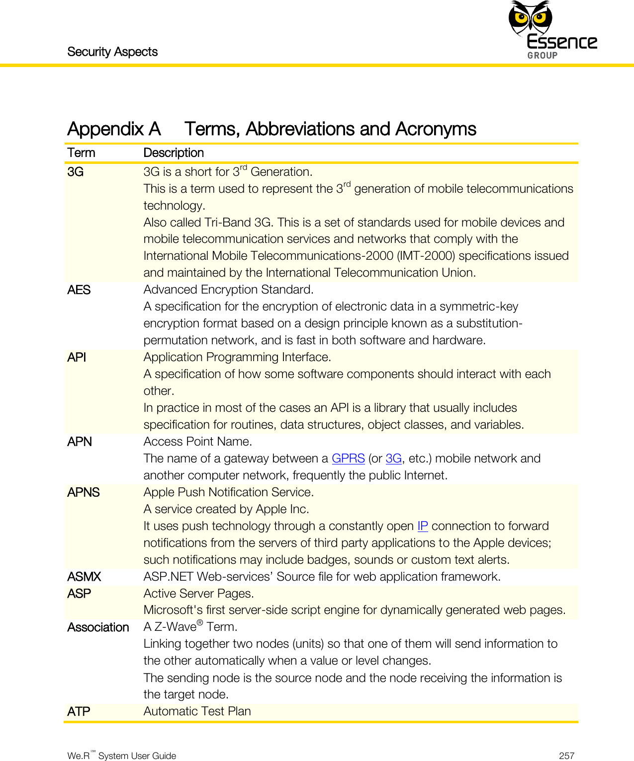
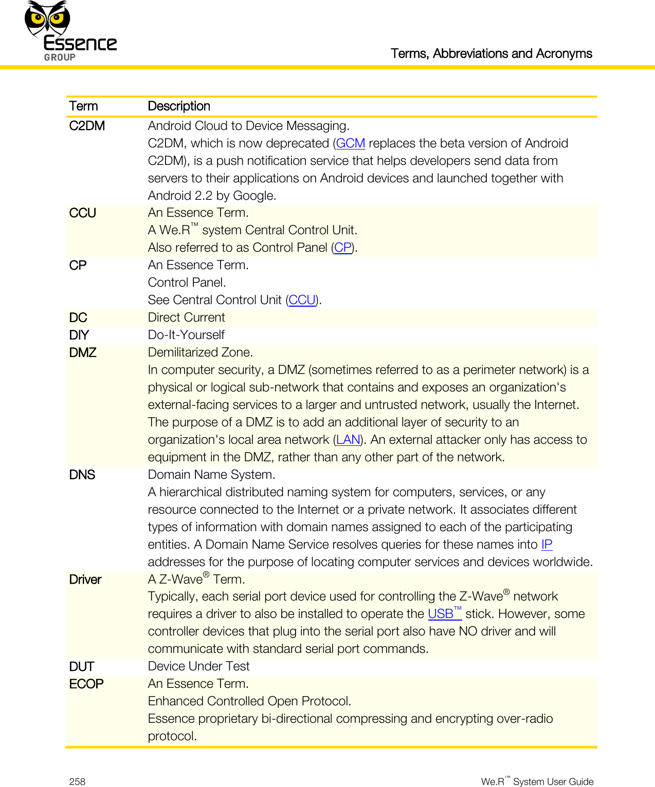
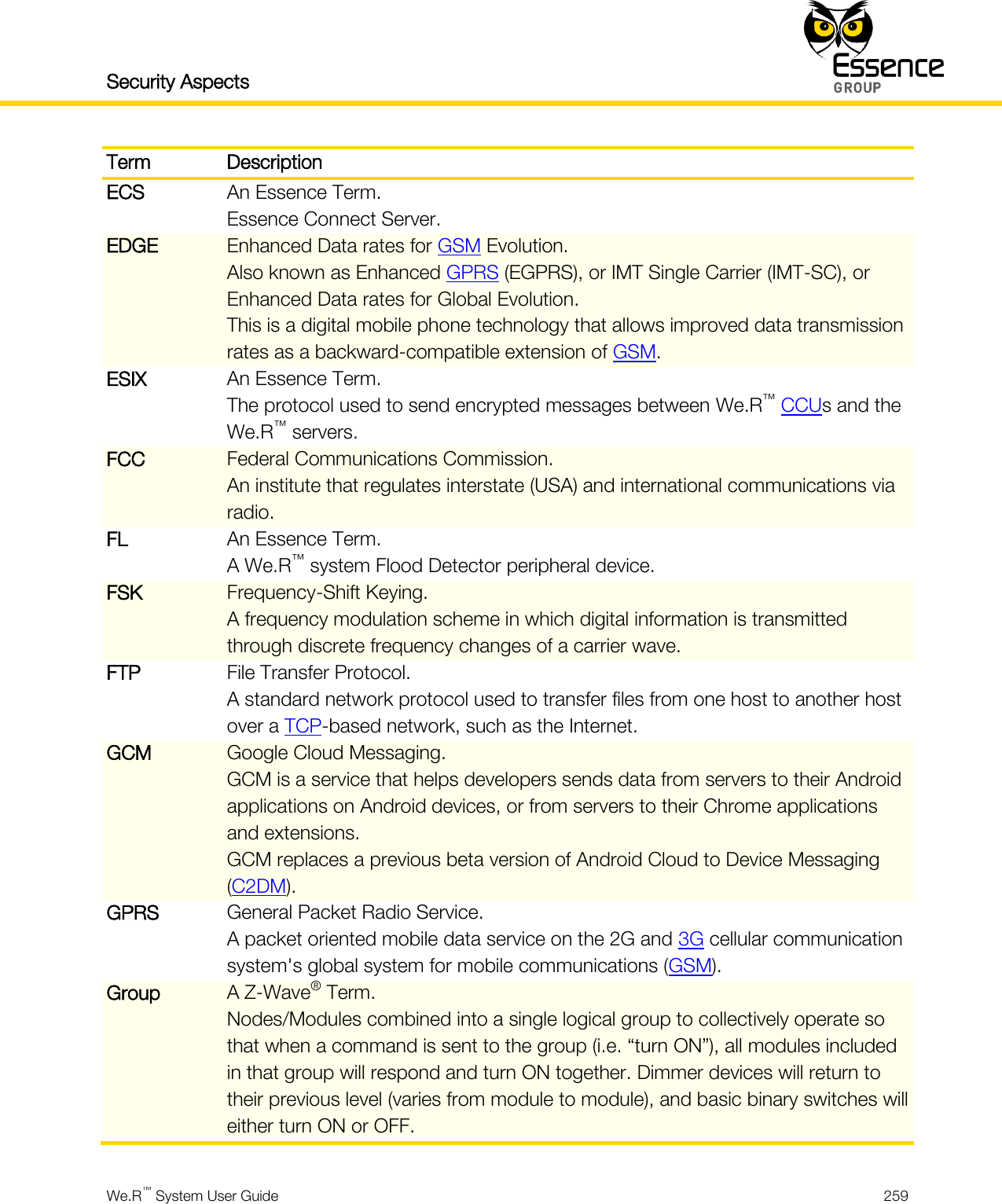
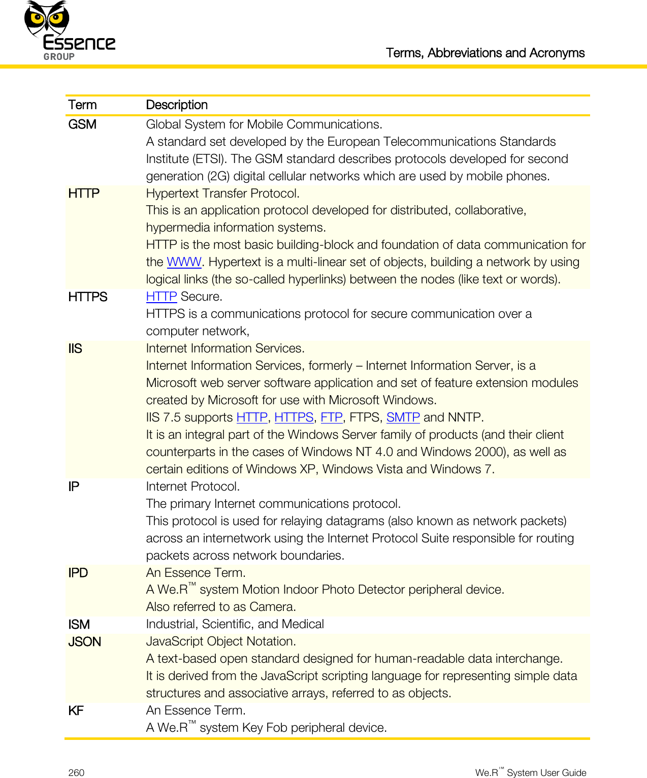
- 5. User_Guide_part8
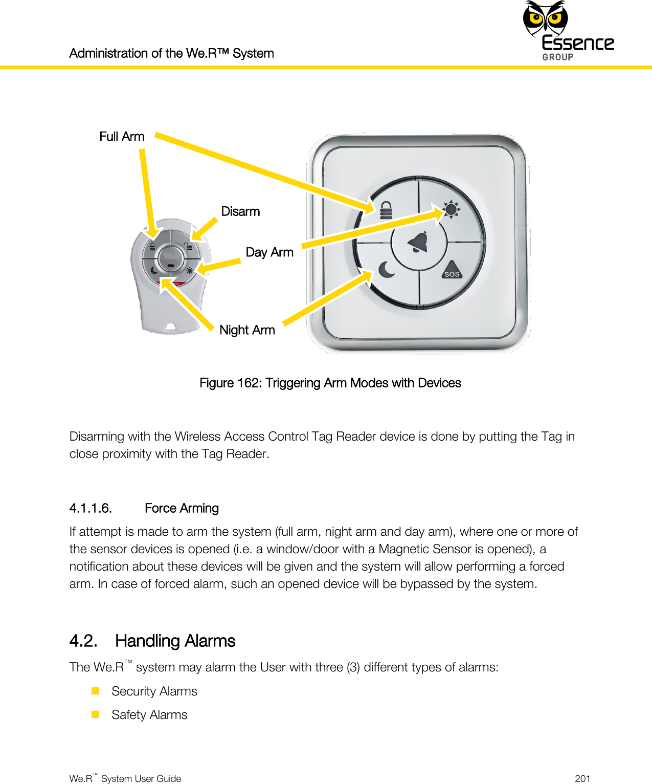
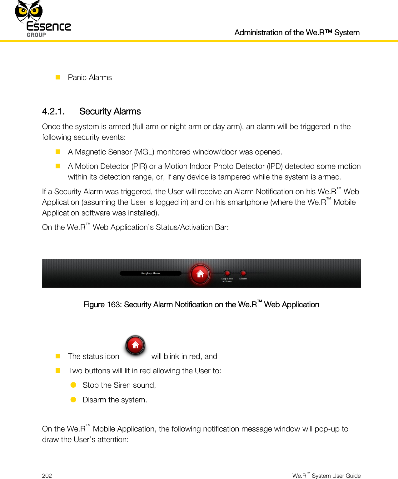
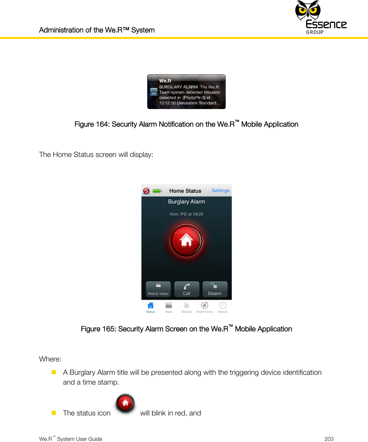
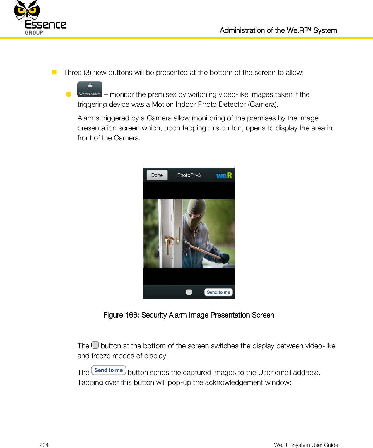
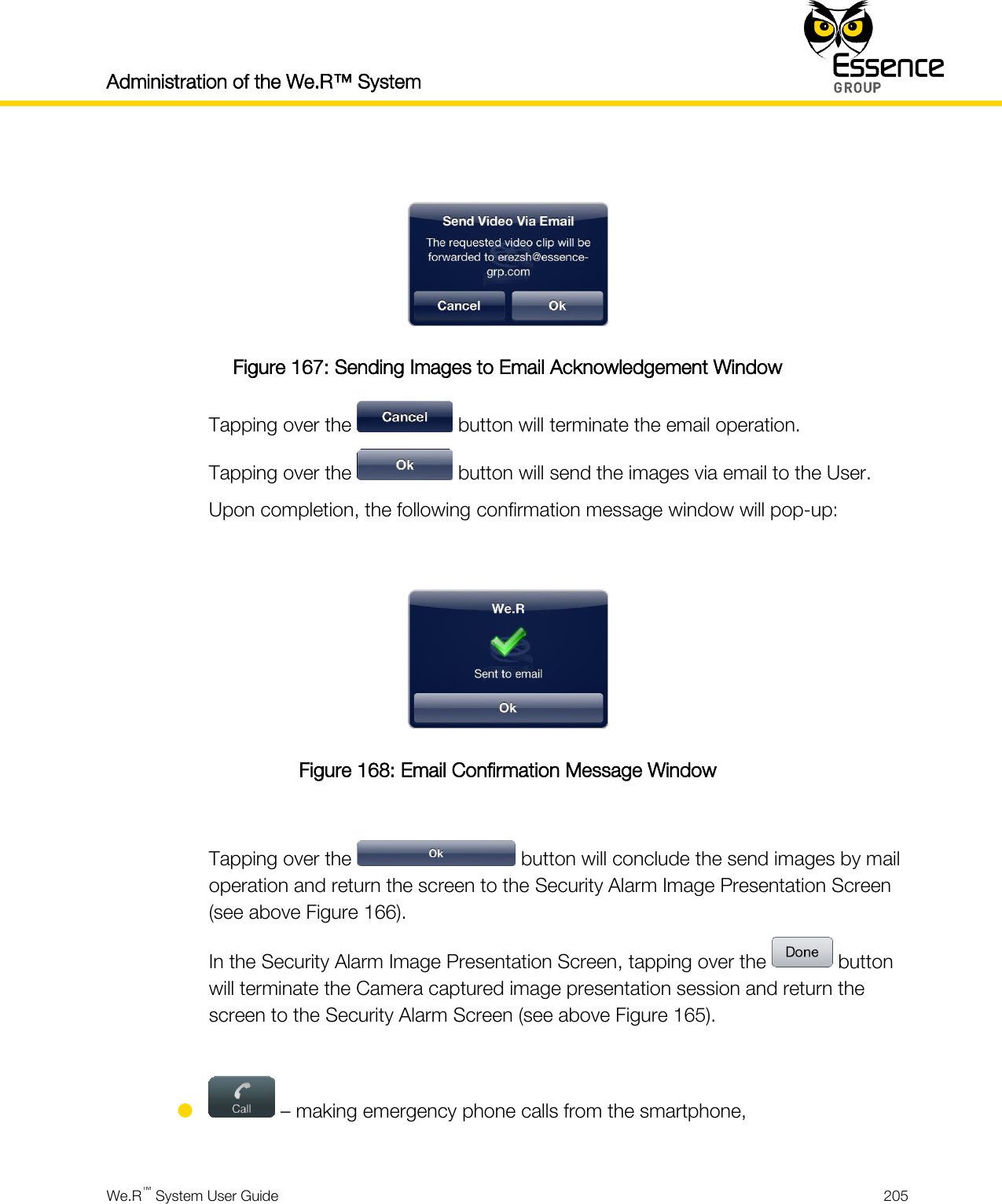
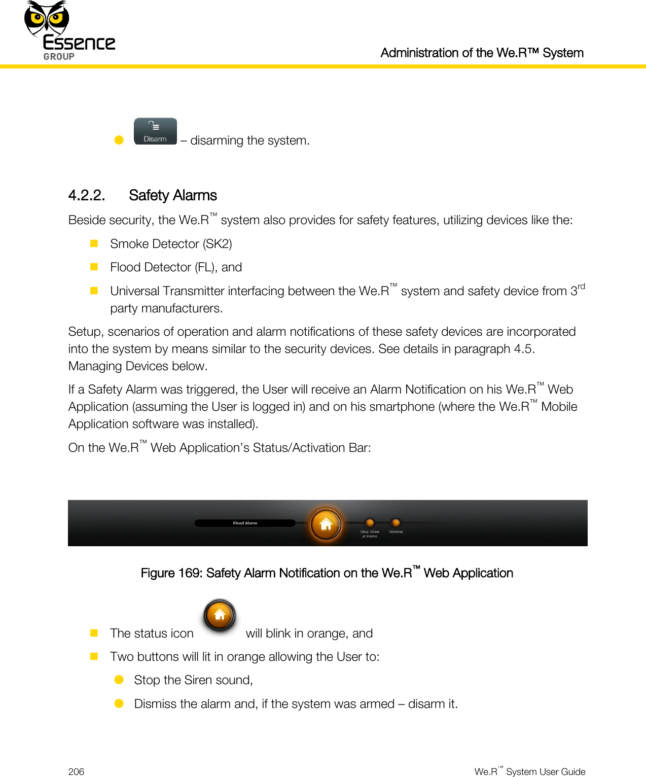
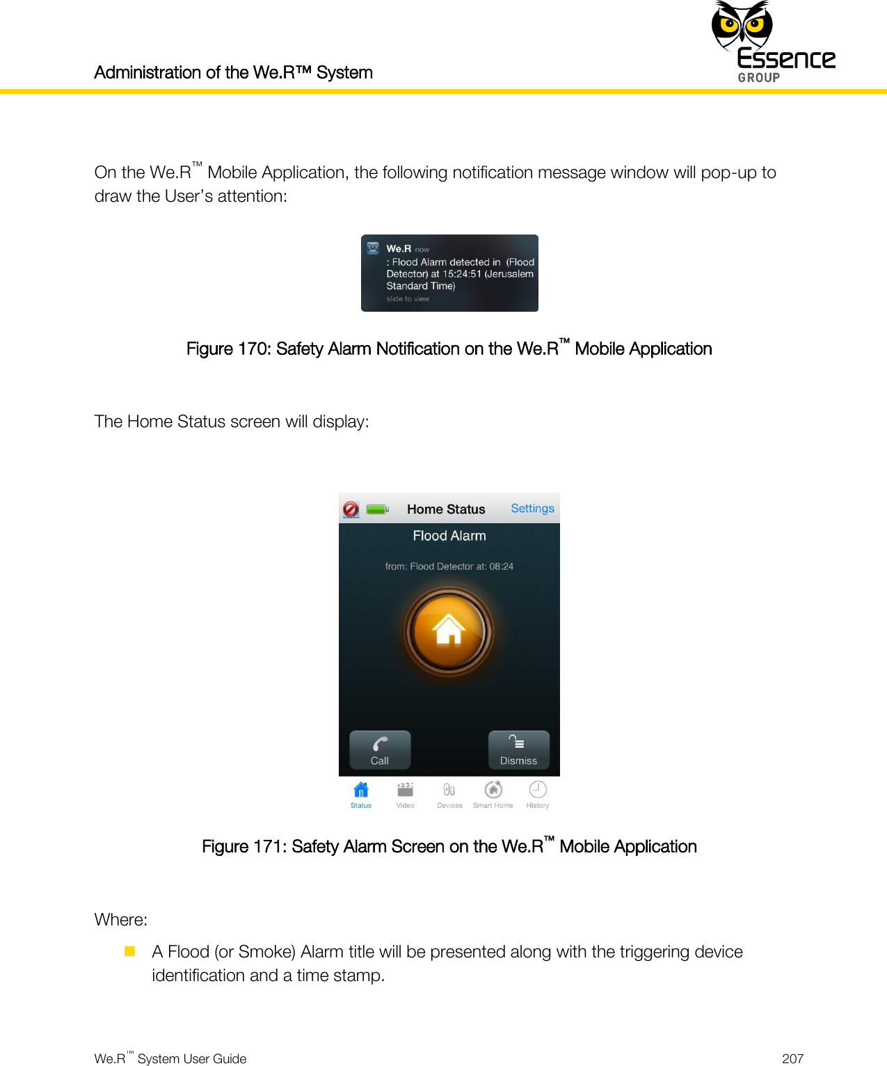
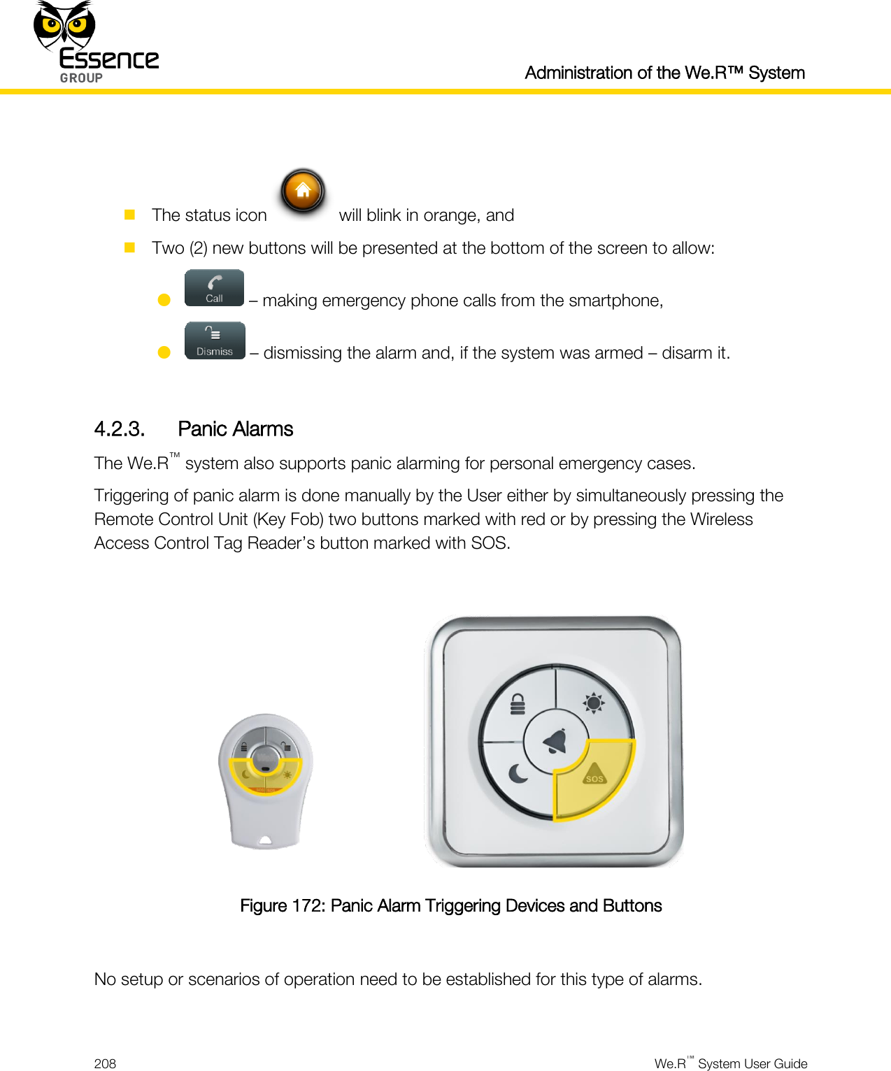
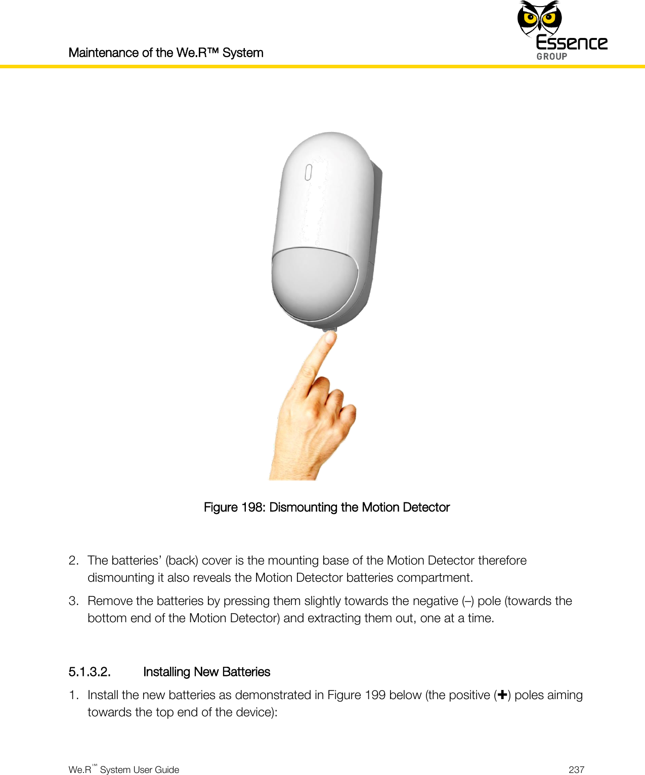
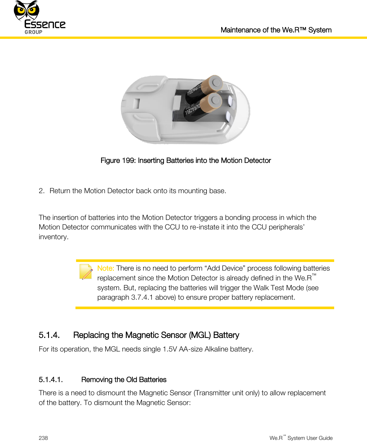
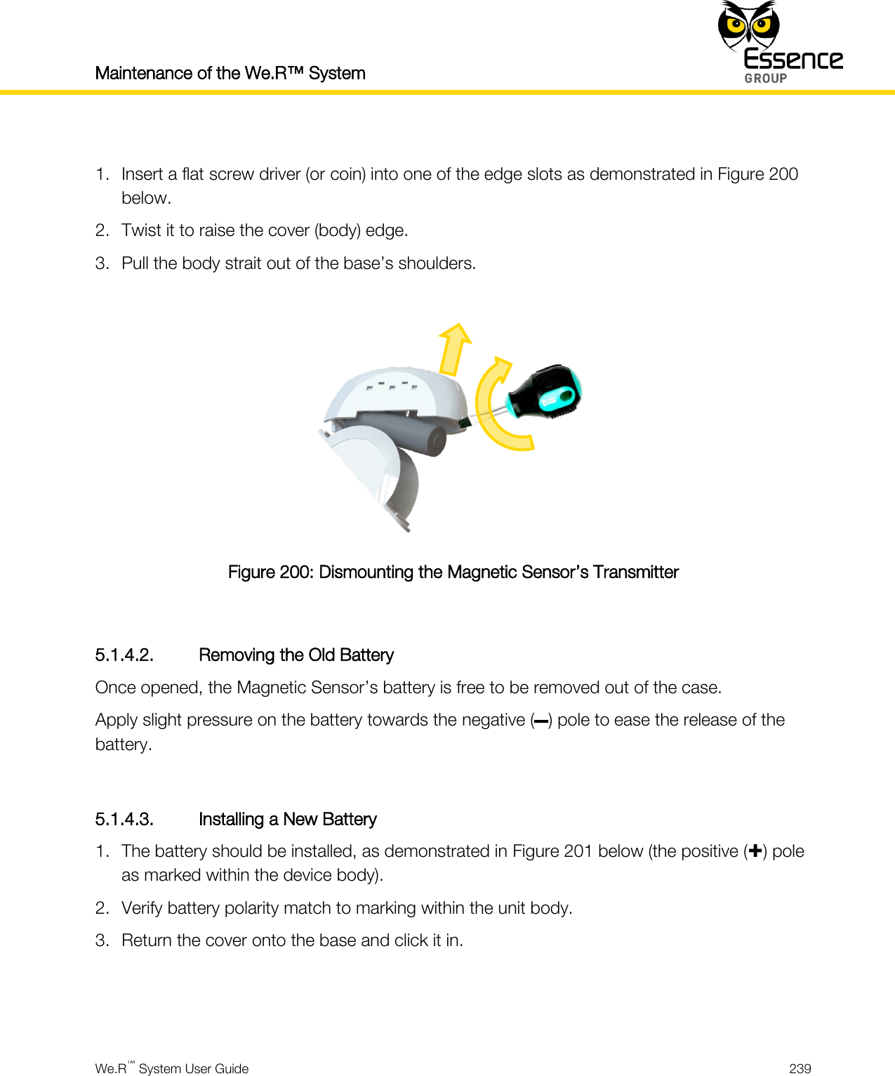
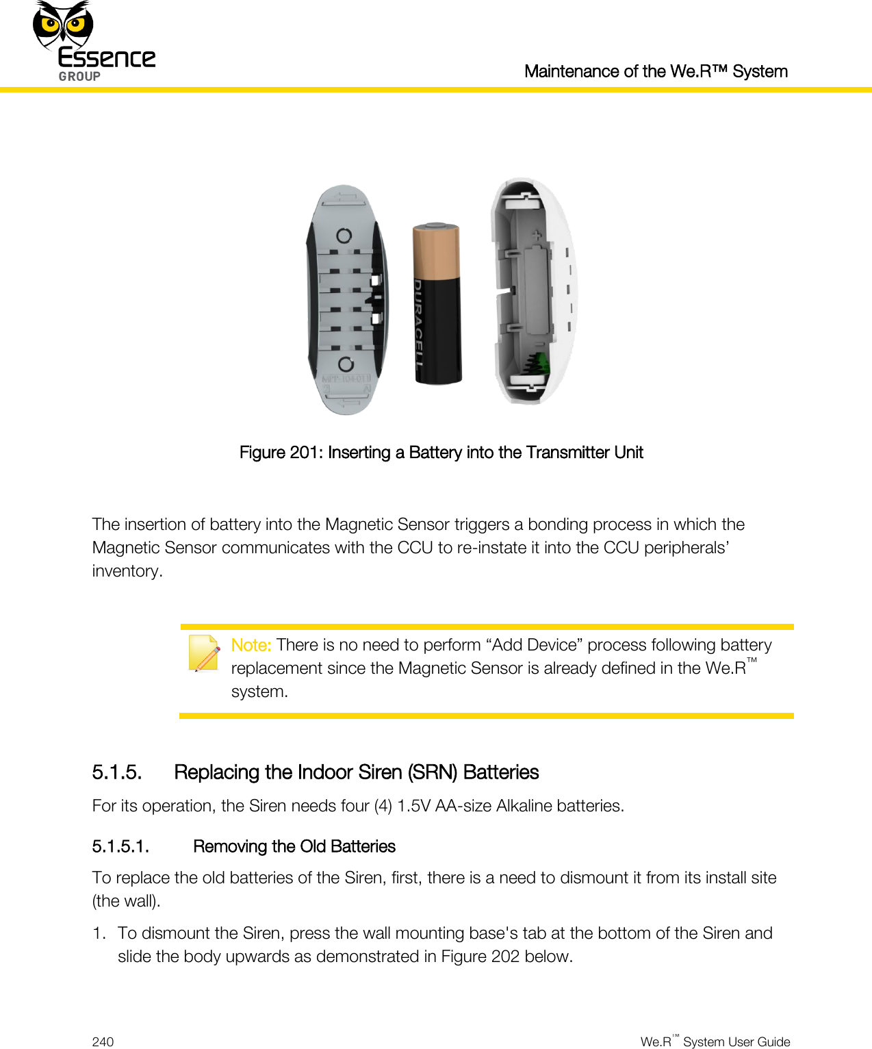
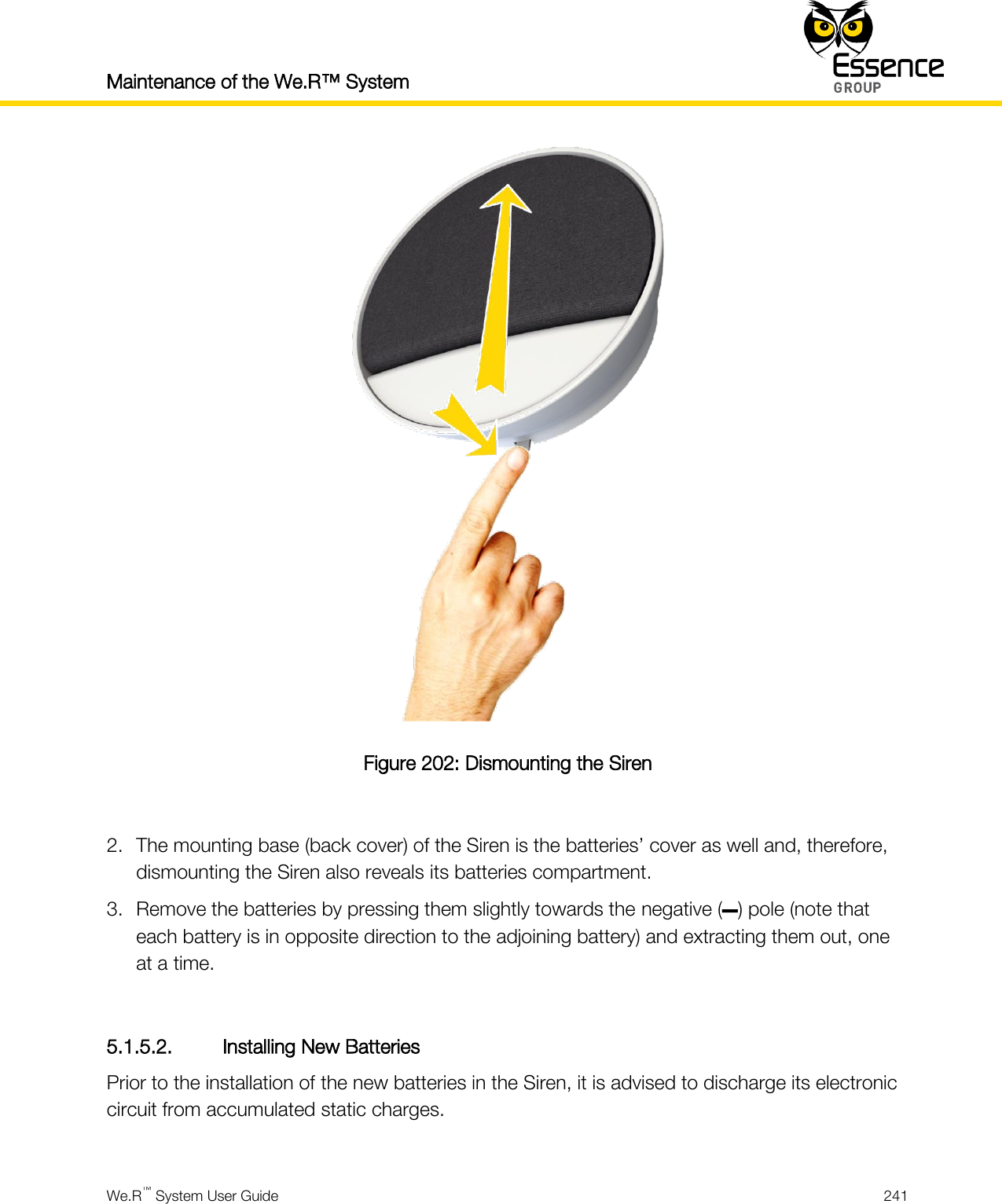
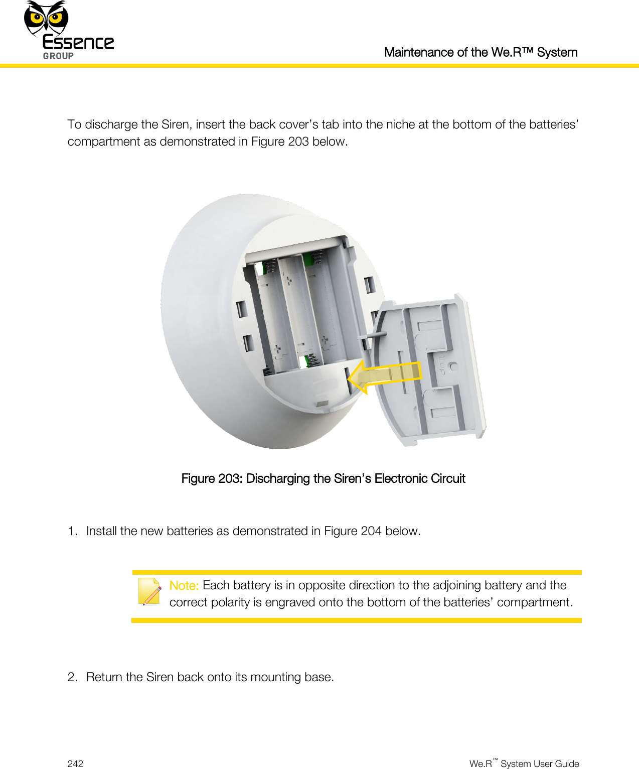
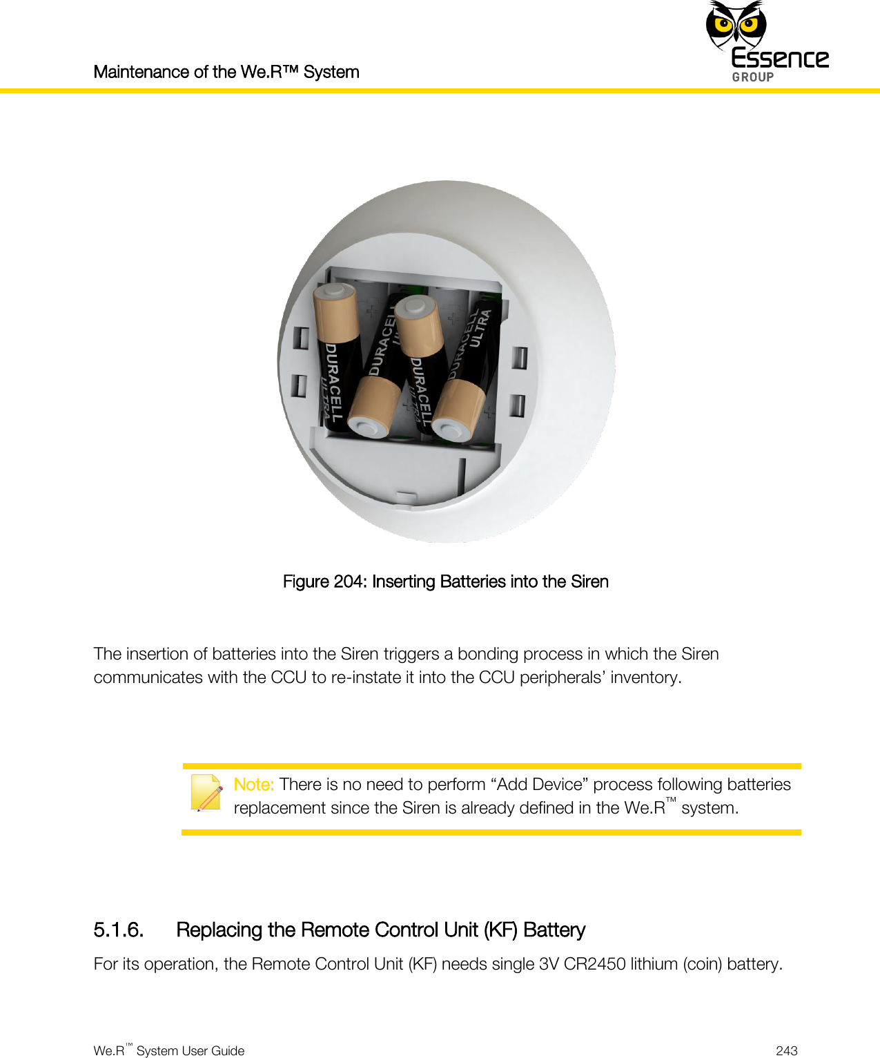
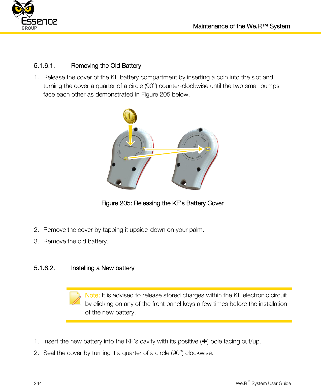
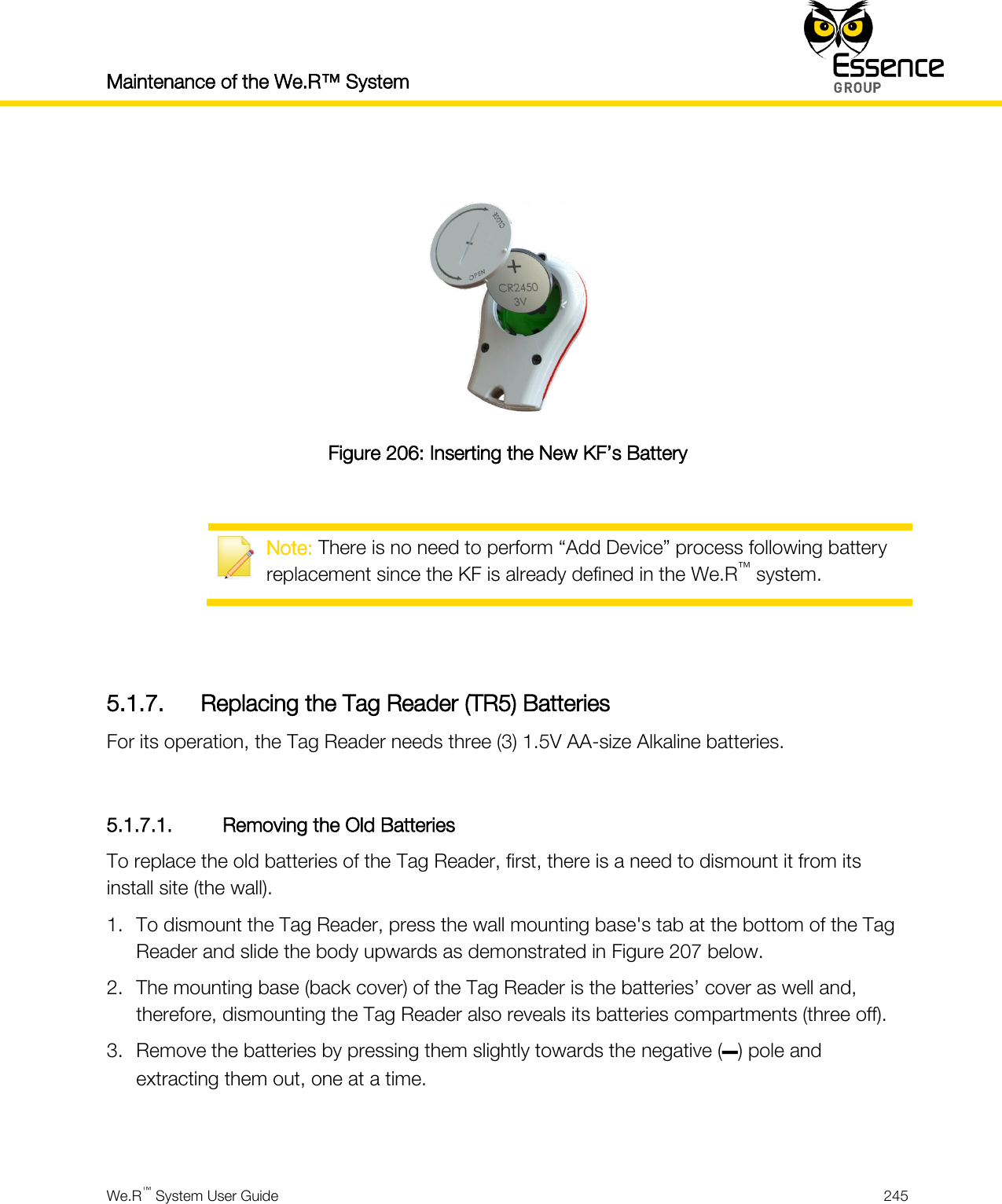
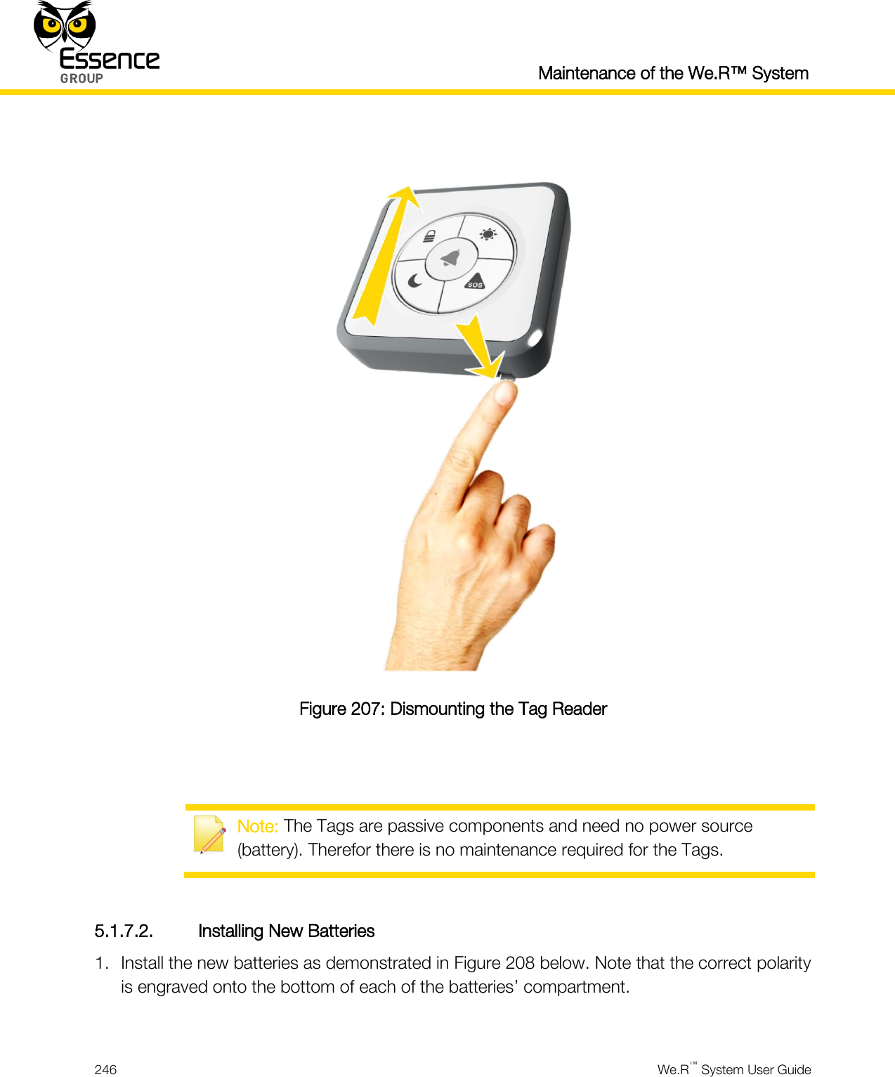
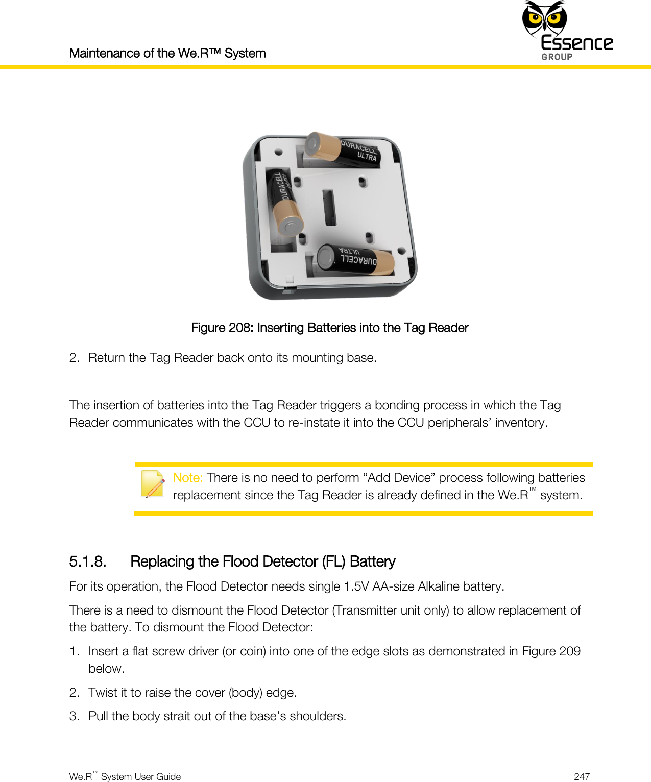
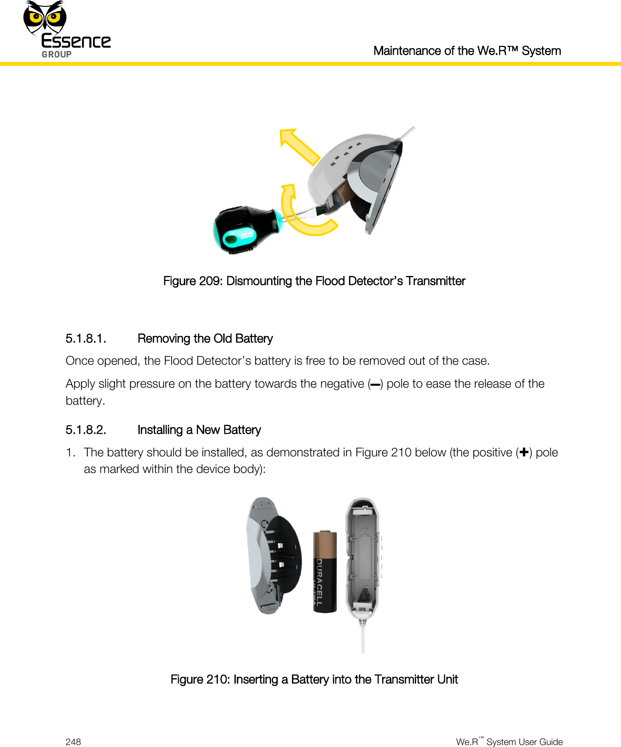
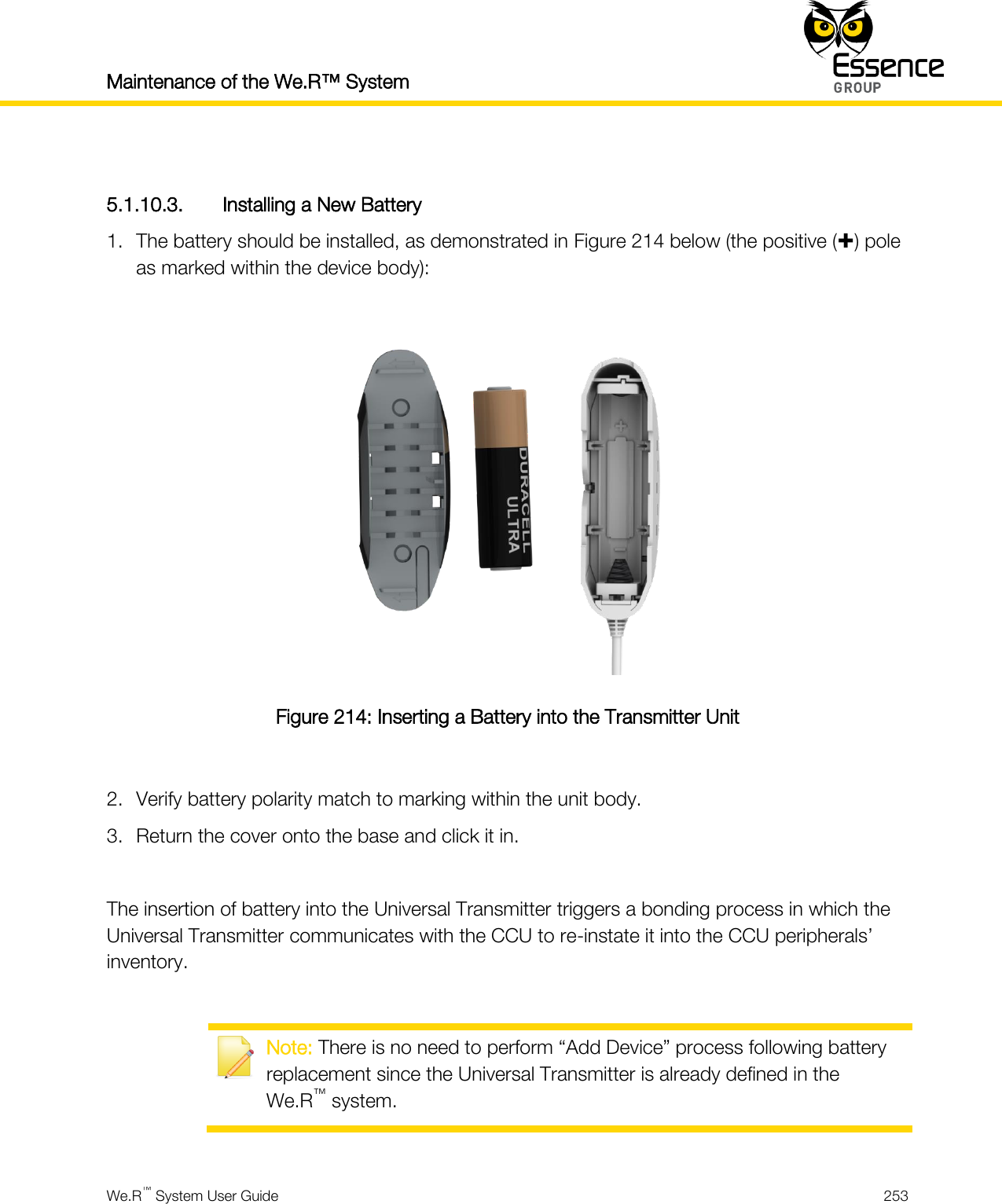
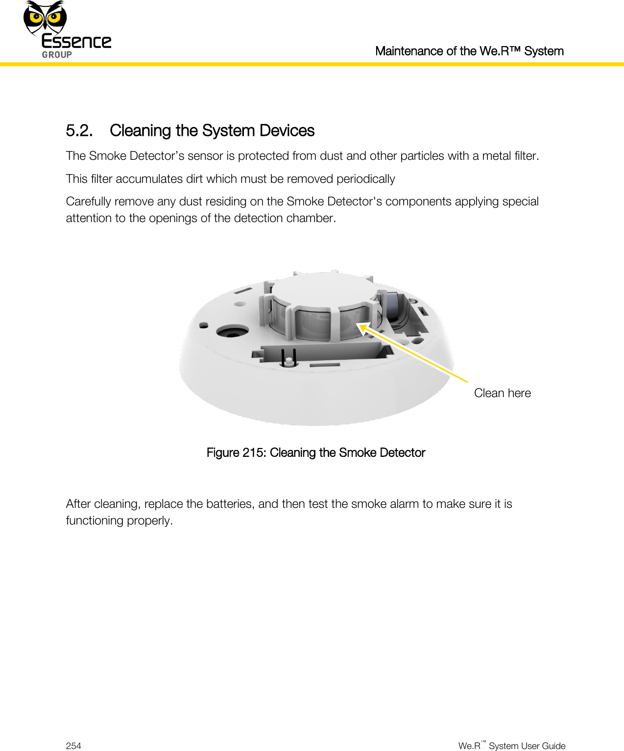
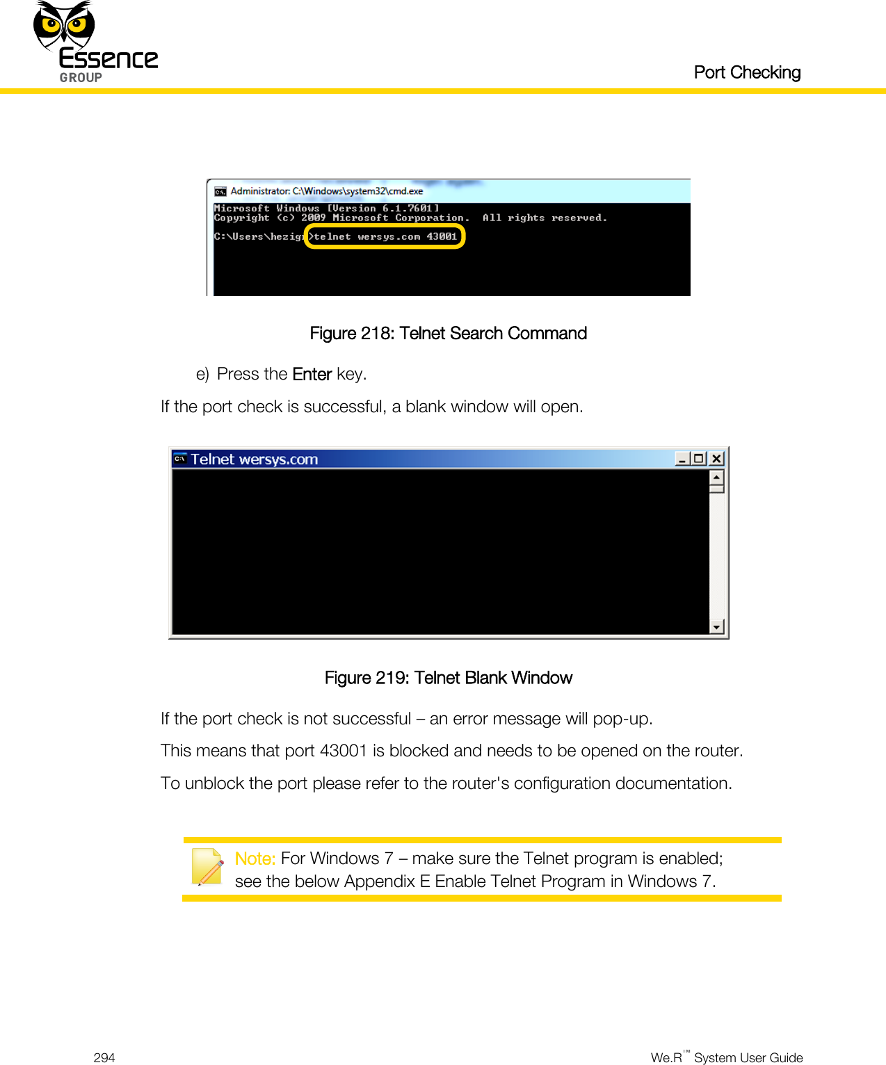
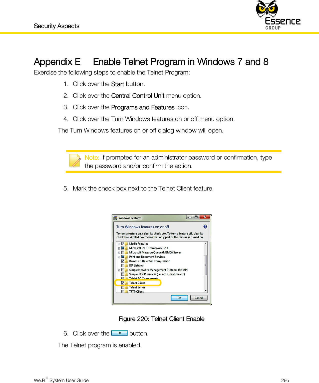
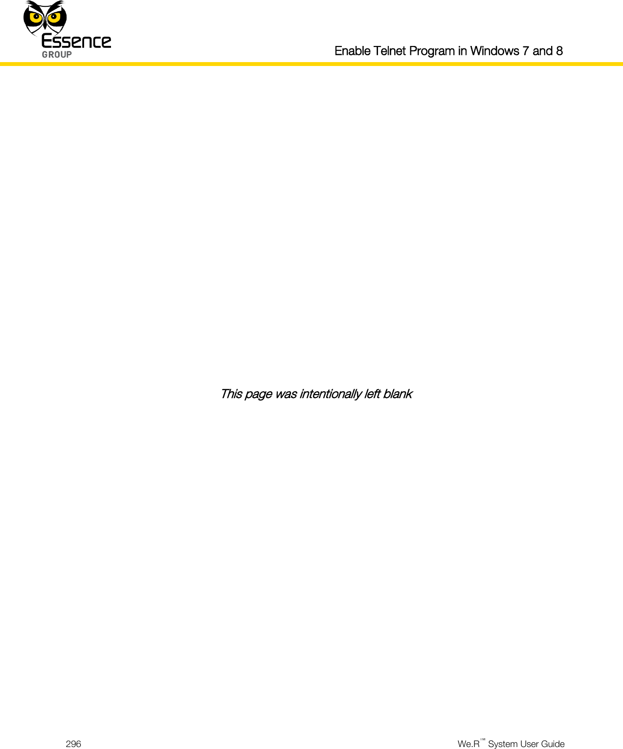
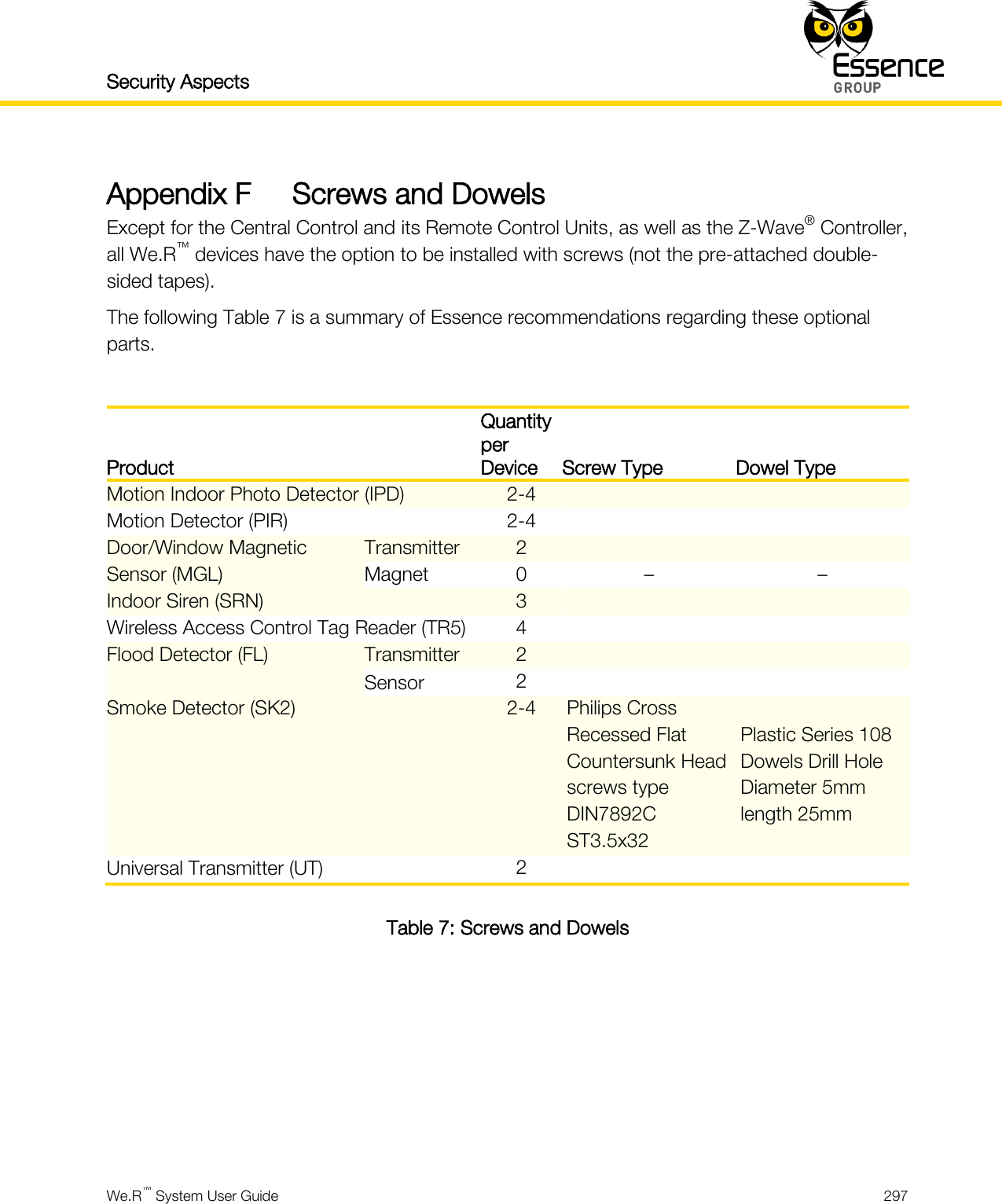
User_Guide_part8