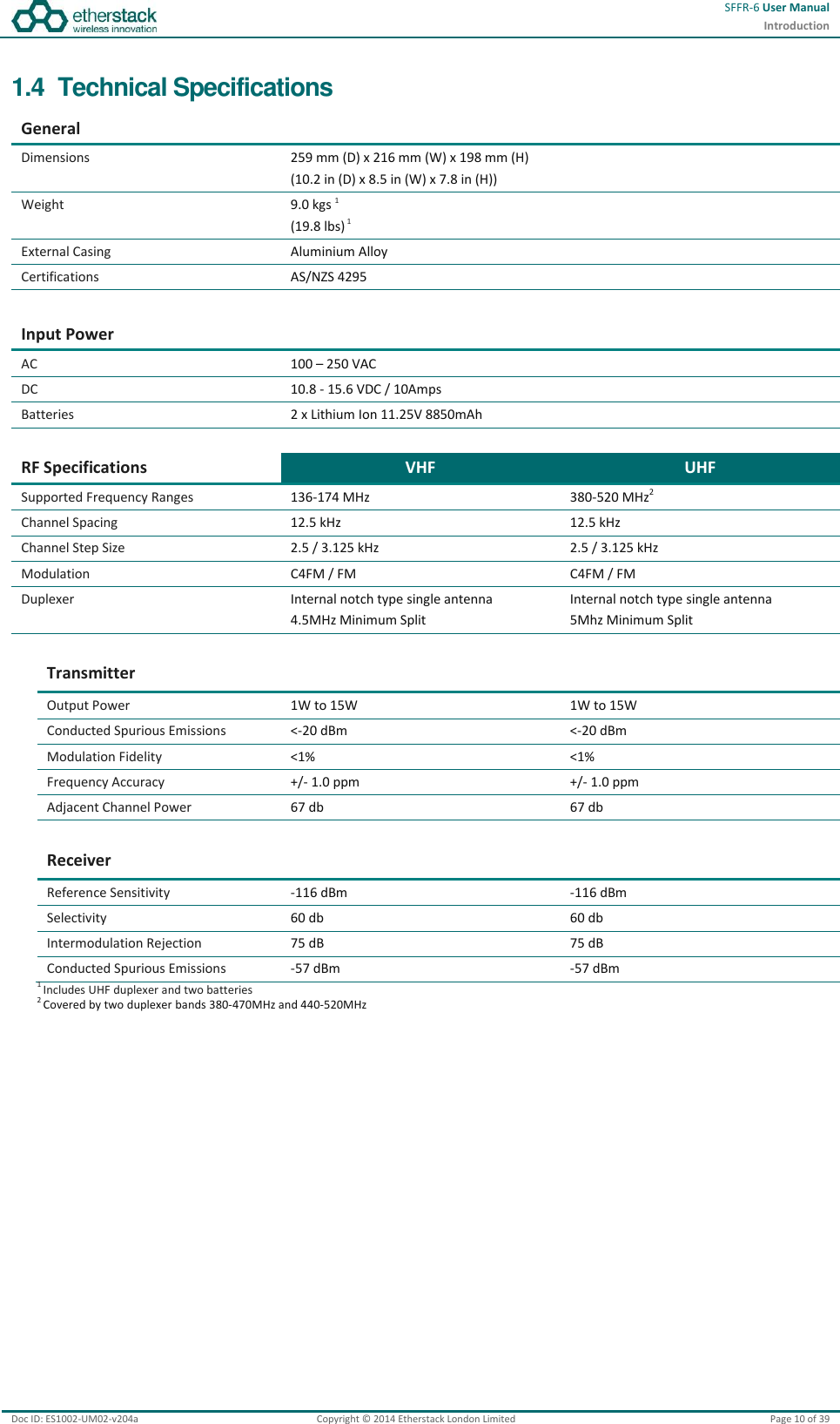
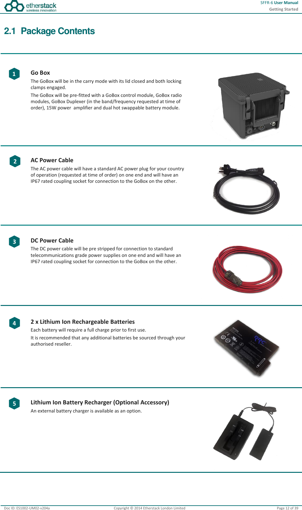
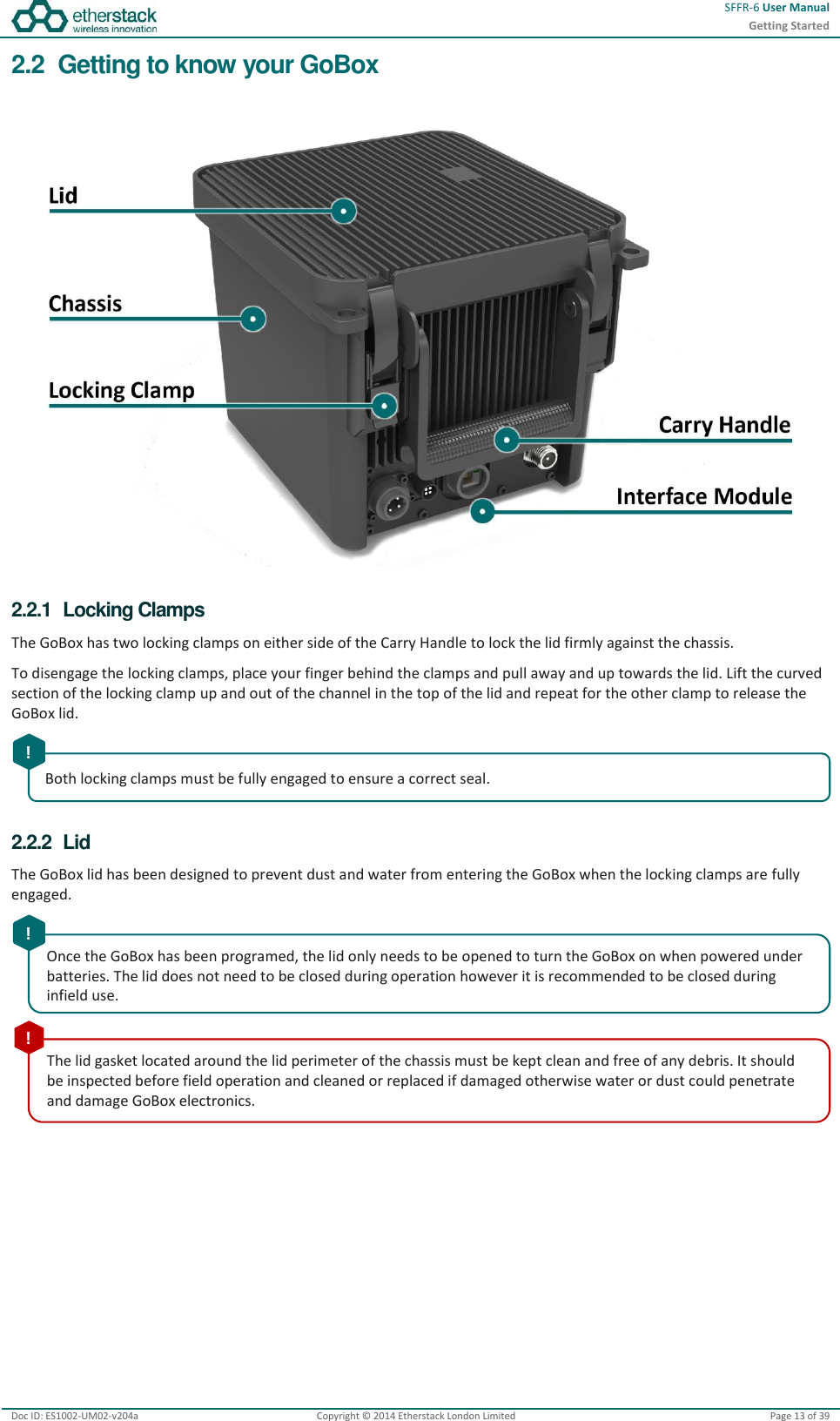
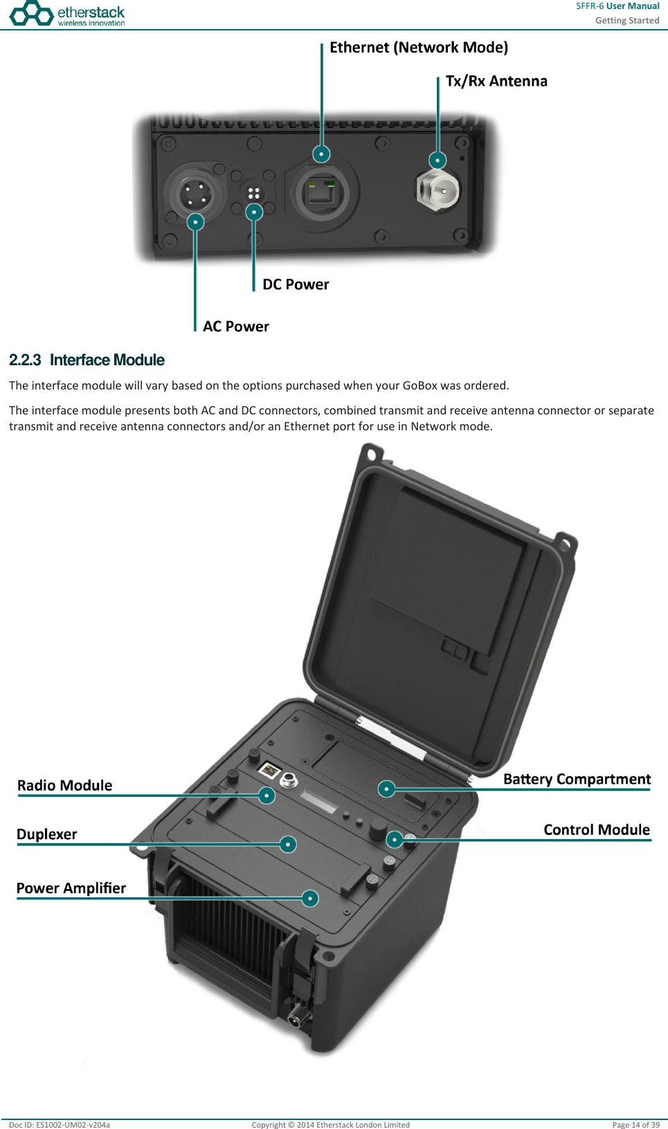
Etherstack SFFR615WUH1 Small Form Factor Repeater User Manual SFFR 6
Etherstack Inc. Small Form Factor Repeater SFFR 6
UserManual.wiki
>
Etherstack
>
SFFR615WUH1 User Manual
User Manual
Navigation menu
Upload a User Manual
Namespaces
Wiki Guide
HTML
PDF
Info
Views
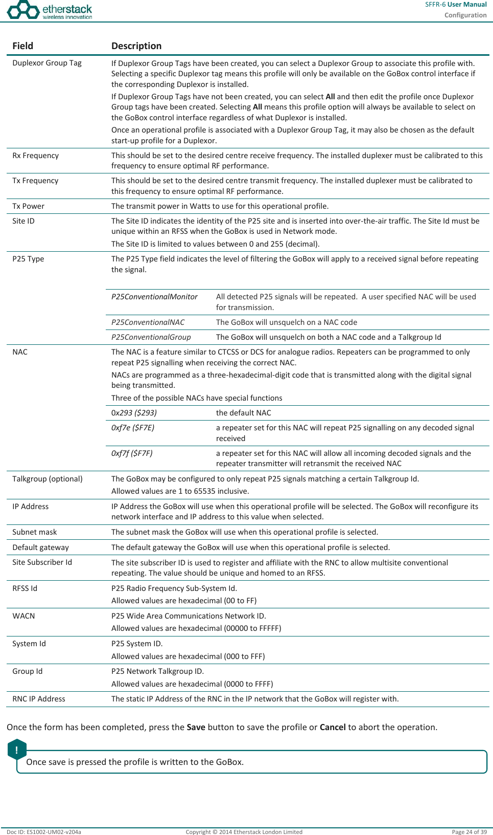
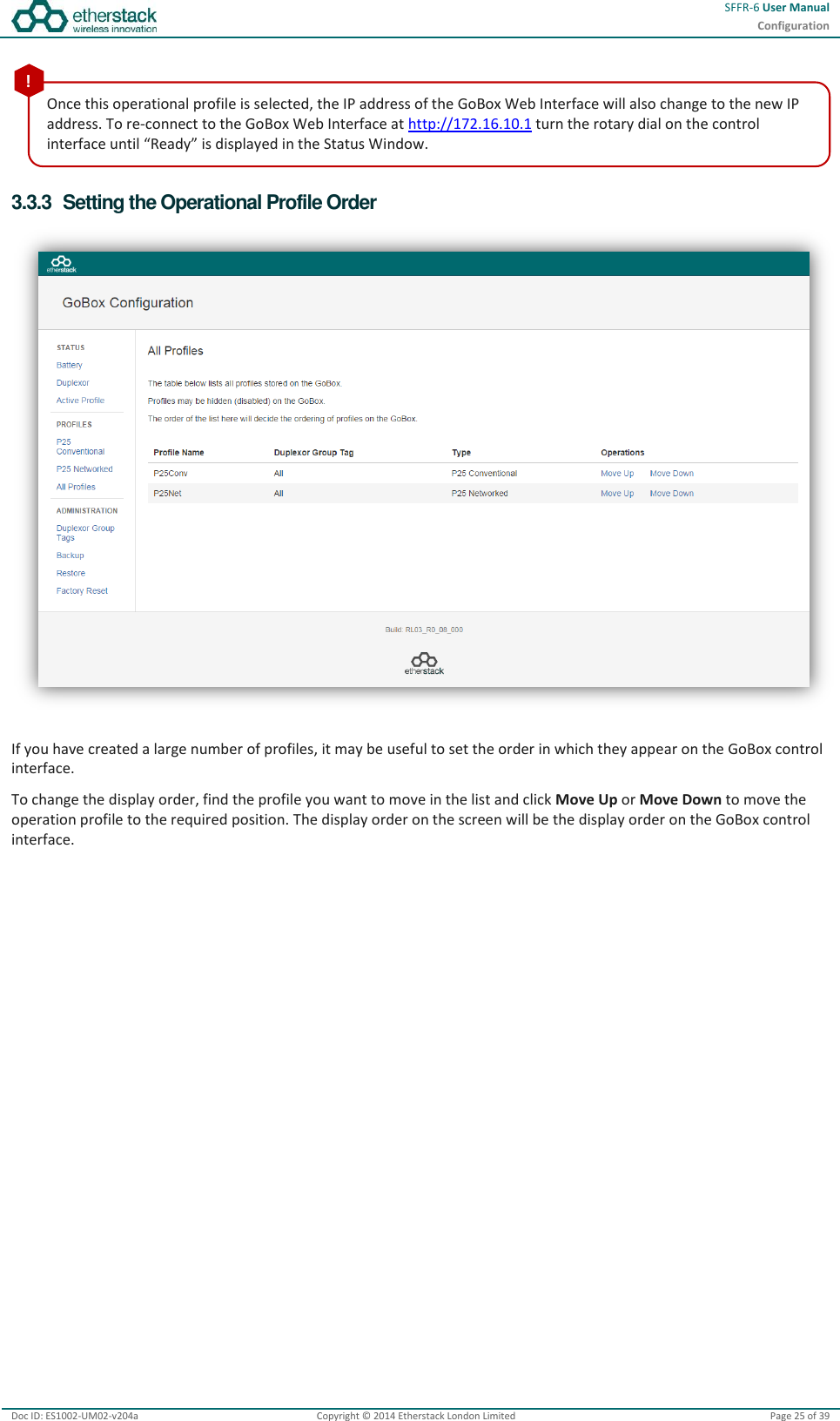
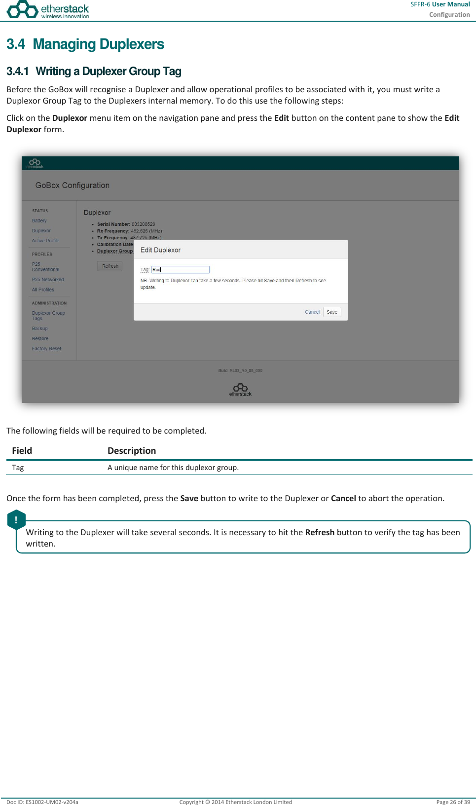
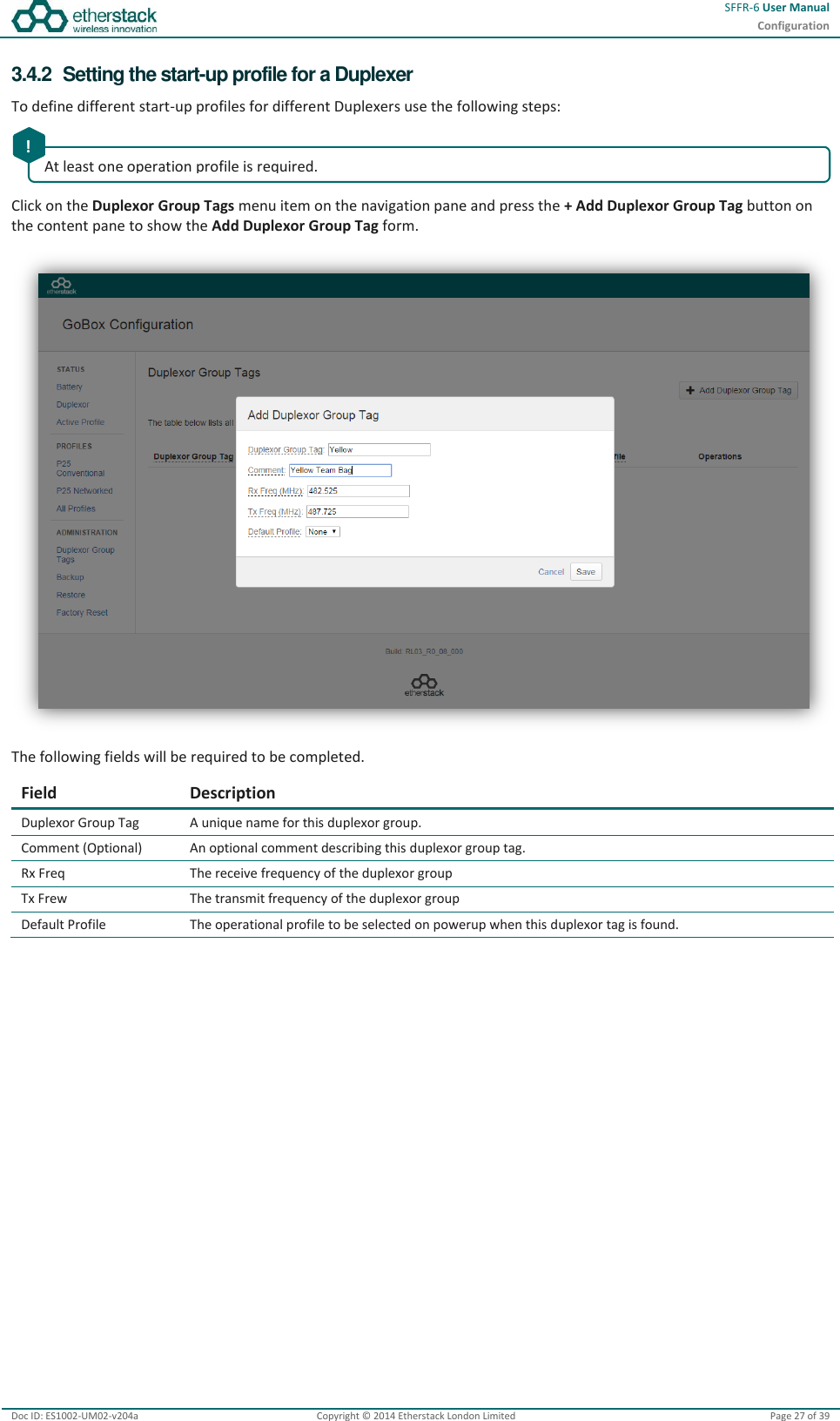
User Manual
Discussion / Help
Navigation