Etiger Digital Technology S4-GSM Alarm system User Manual
Shanghai Etiger Digital Technology Co., Ltd. Alarm system Users Manual
UserManual.wiki
>
Etiger Digital Technology
>
S4 GSM User Manual
Users Manual
Navigation menu
Upload a User Manual
Namespaces
Wiki Guide
HTML
PDF
Info
Views
User Manual
Discussion / Help
Navigation
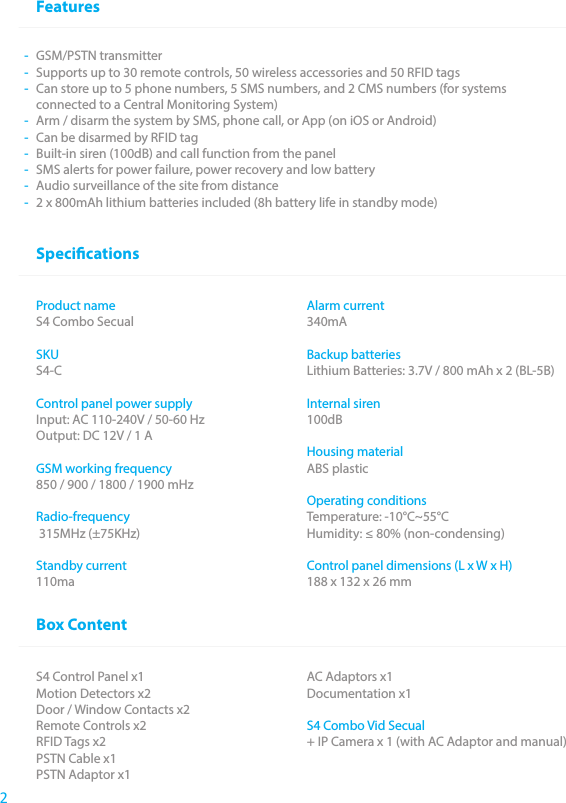
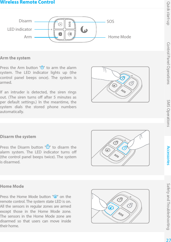
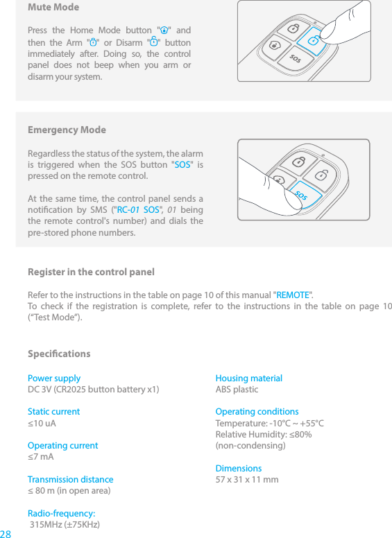
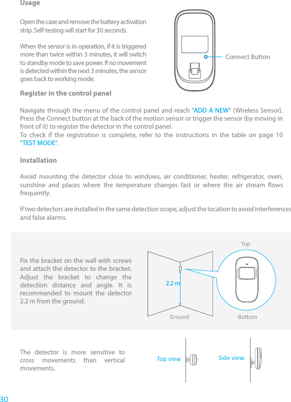
![Accessories Safety and TroubleshootingQuick start-up Control Panel Operations SMS Operations9Arm the System Press the Arm button " " on the control panel. The control panel beeps once: the system is armed.NoteIf the Entry / Exit Delay is activated, only the Delay zone will be armed after the delay set (refer to the instructions on page 12 of this manual “Entry / Exit Delay”).Disarm the System Type your user code and press the Disarm button " " on the control panel. The control panel beeps twice: the system is disarmed.Default user code: 1234Home Mode Press the Stay button " " on the control panel. The control panel beeps once: the system is armed in Home Mode.All the sensors assigned to the Normal zone are armed. The sensors assigned to the Home zone are disarmed. For more information on zone setup, please refer to the instructions on page 17 of this manual.Emergency Mode Hold the “#SOS” button for 3 seconds. The alarm is triggered immediately and the siren rings out. At the same time, the control panel dials the stored phone numbers.Setup from the Control Panel The control panel of your alarm system features an LCD display that enables you to navigate through the menu of the control panel and set up your alarm system. To enter the setting menu, type [your admin code + Enter] on the control panel.Default admin code: 123456In the table on the next page, each column represents a menu or a sub menu. Each menu or submenu will be displayed on one of the two lines of the LCD display. On the LCD display, the current menu, submenu, or setting is shown on the line at the bottom, while the previous menu or submenu is shown on the line at the top.Navigate and select the setting you wish to modify with the keys “ ” or “ ”, and enter each menu or sub menu by pressing “Enter”.How to use the keyboard“ “ = delete“” = move forward“ ” = move backward“Enter” = select / conrm“Esc” = back / previous step in the menu / cancelThe tables on the next pages summarize all the settings that can be accessed and modied on the control panel.9](https://usermanual.wiki/Etiger-Digital-Technology/S4-GSM/User-Guide-2397588-Page-9.png)
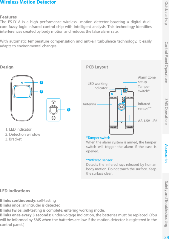
![Main Menu Sub Menu 1 Sub Menu 2 Sub Menu 3 Comments NotePHONE NUMBERSPHONE [1~5] IS:Select the phone or SMS number you want to edit, type in the phone number and conrm with the key "Enter". Use the key " " to clear.5 phone numbers, 5 SMS numbers and 2 CMS numbers can be stored in the control panel.If you want to set a CMS center phone number, please refer to the instructions on page 17 of this manual.SMS NUM [1~5] IS:CMS NUM [1~2] IS: ACCESSORIES REMOTE ADD A NEW The LCD screen displays “PLS CONNECT 30”: press any button on the remote control within the next 30 seconds (the countdown is indicated on the screen after "PLS CONNECT", in seconds). You hear one beep, the LCD screen displays “ADD OK! REMOTE [01~30]”: the connection is successful.DELETE ALL? 1=YES 0=NODELETE ONE ENTER 0130: Select the remote control you wish to delete.ACCESSORIES RFID TAGADD A NEW PLS CONNECTThe LCD screen displays “PLS CONNECT 30”: swipe the RFID tag in front of the RFID reader on the control panel within the next 30 seconds (the countdown is indicated on the screen after "PLS CONNECT", in seconds). You hear one beep, the LCD screen displays “ADD OK! RFID [01~50]”, the connection is successfulDELETE ALL? 1=YES 0=NODELETE ONE ENTER 0150 Select the RFID tag you wish to deleteACCESSORIES WIRELESS SENSORSADD A NEWNORMAL SENSOR HOME SENSOR DELAY SENSOR 24 HOUR SENSORSelect the sensor type you wish your sensor to be assigned to (Normal Sensor, 24 Hour Sensor, Delay Sensor, or Home Sensor), press “Enter” to conrm.The LCD screen displays “PLS CONNECT 30”: trigger the detector once within the next 30 seconds (the countdown is indicated on the screen after "PLS CONNECT", in seconds). You hear one beep, the LCD screen displays “ADD OK! SENSOR 01~50”, the connection is successful.For more information on zone setup, refer to the instructions on page 17.DELETE ALL? 1=YES 0=NODELETE ONE ENTER 0150:ACCESSORIES TEST MODE Trigger the sensors you have previously connected to the control panel. You hear 1 beep, the LCD screen displays the signals that have been respectively sent by each sensor triggered. Make sure all the sensors you have triggered are mentioned on the LCD screen. Press “Esc” to exit the test mode.This mode enables you to test if the sen-sors have been connected successfully to the control panel.10](https://usermanual.wiki/Etiger-Digital-Technology/S4-GSM/User-Guide-2397588-Page-10.png)
![Accessories Safety and TroubleshootingQuick start-up Control Panel Operations SMS OperationsMain Menu Sub Menu 1 Sub Menu 2 Sub Menu 3 Comments NotePHONE NUMBERSPHONE [1~5] IS:Select the phone or SMS number you want to edit, type in the phone number and conrm with the key "Enter". Use the key " " to clear.5 phone numbers, 5 SMS numbers and 2 CMS numbers can be stored in the control panel.If you want to set a CMS center phone number, please refer to the instructions on page 17 of this manual.SMS NUM [1~5] IS:CMS NUM [1~2] IS: ACCESSORIES REMOTE ADD A NEW The LCD screen displays “PLS CONNECT 30”: press any button on the remote control within the next 30 seconds (the countdown is indicated on the screen after "PLS CONNECT", in seconds). You hear one beep, the LCD screen displays “ADD OK! REMOTE [01~30]”: the connection is successful.DELETE ALL? 1=YES 0=NODELETE ONE ENTER 0130: Select the remote control you wish to delete.ACCESSORIES RFID TAGADD A NEW PLS CONNECTThe LCD screen displays “PLS CONNECT 30”: swipe the RFID tag in front of the RFID reader on the control panel within the next 30 seconds (the countdown is indicated on the screen after "PLS CONNECT", in seconds). You hear one beep, the LCD screen displays “ADD OK! RFID [01~50]”, the connection is successfulDELETE ALL? 1=YES 0=NODELETE ONE ENTER 0150 Select the RFID tag you wish to deleteACCESSORIES WIRELESS SENSORSADD A NEWNORMAL SENSOR HOME SENSOR DELAY SENSOR 24 HOUR SENSORSelect the sensor type you wish your sensor to be assigned to (Normal Sensor, 24 Hour Sensor, Delay Sensor, or Home Sensor), press “Enter” to conrm.The LCD screen displays “PLS CONNECT 30”: trigger the detector once within the next 30 seconds (the countdown is indicated on the screen after "PLS CONNECT", in seconds). You hear one beep, the LCD screen displays “ADD OK! SENSOR 01~50”, the connection is successful.For more information on zone setup, refer to the instructions on page 17.DELETE ALL? 1=YES 0=NODELETE ONE ENTER 0150:ACCESSORIES TEST MODE Trigger the sensors you have previously connected to the control panel. You hear 1 beep, the LCD screen displays the signals that have been respectively sent by each sensor triggered. Make sure all the sensors you have triggered are mentioned on the LCD screen. Press “Esc” to exit the test mode.This mode enables you to test if the sen-sors have been connected successfully to the control panel.11](https://usermanual.wiki/Etiger-Digital-Technology/S4-GSM/User-Guide-2397588-Page-11.png)
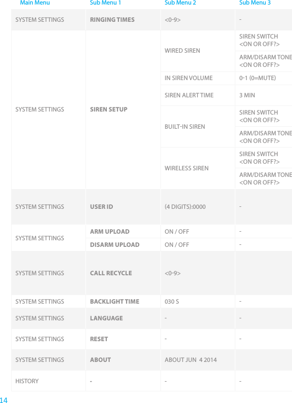
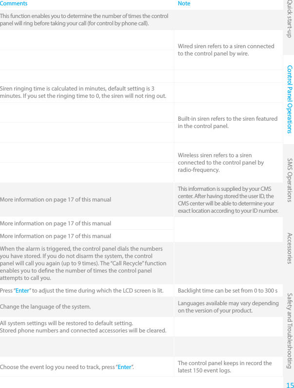
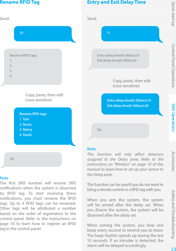
![Main Menu Sub Menu 1 Sub Menu 2 Sub Menu 3 Comments NoteSYSTEM SETTINGS DATE AND TIME YYYYMMDD TIME e.g. 20140620 14H30SYSTEM SETTINGS ENTRY EXIT DELAYENTRY DELAY 000300 This function can be used if you do not want to bring a remote control or RFID tag with you. When the system is armed, you hear one beep every second to remind you to leave. The beep rhythm speeds up during the last 10 seconds. If an intruder is detected, the alarm will be delayed accordingly.Time is calculated in seconds. The Entry and Exit Delay can be set from 0 to 300 seconds.The entry and exit delay is only for sensors connected as Delay Zone accessories (see "Wireless" on page 10).The Entry Delay gives you time to disarm the system on the control panel without triggering an alarm.The Exit Delay gives you time to arm the system on the control panel and leave your home without triggering an alarm.EXIT DELAY 000300SYSTEM SETTINGS AUTO ARM / DISARMAUTO ARM TIME <00:00>You can set up the system to arm and disarm automatically at a dened time every day.Setting Auto Arm and Auto Disarm to the exact same time will deactivate the function.AUTO DISARM TIME <00:00>ON OR OFF?SYSTEM SETTINGS CONTROL BY PHONE ON / OFF You can activate or deactivate the control of your system by phone call. Activating the control by phone call enables you to arm and disarm the system and monitor your home by phone call.See instructions on page 16 for more information on the control of the system by phone call.SYSTEM SETTINGS LINECUT ALARM ON / OFF If the linecut alarm is on, the alarm will be triggered if your telephone line is down. The rst SMS number stored receives a notication by SMS (only in GSM mode).Deactivate this function if you want to use the alarm system in GSM mode only.SYSTEM SETTINGS GSM FAIL TIP ON / OFF Notication of SIM/ GSM signal problem. Deactivate this function if you want to use the alarm system in PSTN mode only.SYSTEM SETTINGS KEYPAD TONES ON / OFF Activate or deactivate the sound when typing on the keyboard of the control panel.SYSTEM SETTINGS ACCESS CODEADMIN CODE 123456 Your admin code enables you to enter the setup menu. Default admin code: 123456It is recommended to change all codes before using your system for the rst time and to keep your codes secretUSER CODE 1234Your user code enables you to disarm the system on the control panel. The user code is the access code requested when you call the control panel. Default user code: 1234DURESS CODE 0000In case of emergency, when you are requested to disarm the sys-tem by force, it is recommended to disarm your system with your Duress Code. The panel will silently dial the stored phone numbers. Default duress code: 0000OPEN DOOR CODE 8888 You can open electronic doors using this code. The door must be wired to the [LOCK] interface on the back of the control panel.12](https://usermanual.wiki/Etiger-Digital-Technology/S4-GSM/User-Guide-2397588-Page-12.png)
![Accessories Safety and TroubleshootingQuick start-up Control Panel Operations SMS OperationsMain Menu Sub Menu 1 Sub Menu 2 Sub Menu 3 Comments NoteSYSTEM SETTINGS DATE AND TIME YYYYMMDD TIME e.g. 20140620 14H30SYSTEM SETTINGS ENTRY EXIT DELAYENTRY DELAY 000300 This function can be used if you do not want to bring a remote control or RFID tag with you. When the system is armed, you hear one beep every second to remind you to leave. The beep rhythm speeds up during the last 10 seconds. If an intruder is detected, the alarm will be delayed accordingly.Time is calculated in seconds. The Entry and Exit Delay can be set from 0 to 300 seconds.The entry and exit delay is only for sensors connected as Delay Zone accessories (see "Wireless" on page 10).The Entry Delay gives you time to disarm the system on the control panel without triggering an alarm.The Exit Delay gives you time to arm the system on the control panel and leave your home without triggering an alarm.EXIT DELAY 000300SYSTEM SETTINGS AUTO ARM / DISARMAUTO ARM TIME <00:00>You can set up the system to arm and disarm automatically at a dened time every day.Setting Auto Arm and Auto Disarm to the exact same time will deactivate the function.AUTO DISARM TIME <00:00>ON OR OFF?SYSTEM SETTINGS CONTROL BY PHONE ON / OFF You can activate or deactivate the control of your system by phone call. Activating the control by phone call enables you to arm and disarm the system and monitor your home by phone call.See instructions on page 16 for more information on the control of the system by phone call.SYSTEM SETTINGS LINECUT ALARM ON / OFF If the linecut alarm is on, the alarm will be triggered if your telephone line is down. The rst SMS number stored receives a notication by SMS (only in GSM mode).Deactivate this function if you want to use the alarm system in GSM mode only.SYSTEM SETTINGS GSM FAIL TIP ON / OFF Notication of SIM/ GSM signal problem. Deactivate this function if you want to use the alarm system in PSTN mode only.SYSTEM SETTINGS KEYPAD TONES ON / OFF Activate or deactivate the sound when typing on the keyboard of the control panel.SYSTEM SETTINGS ACCESS CODEADMIN CODE 123456 Your admin code enables you to enter the setup menu. Default admin code: 123456It is recommended to change all codes before using your system for the rst time and to keep your codes secretUSER CODE 1234Your user code enables you to disarm the system on the control panel. The user code is the access code requested when you call the control panel. Default user code: 1234DURESS CODE 0000In case of emergency, when you are requested to disarm the sys-tem by force, it is recommended to disarm your system with your Duress Code. The panel will silently dial the stored phone numbers. Default duress code: 0000OPEN DOOR CODE 8888 You can open electronic doors using this code. The door must be wired to the [LOCK] interface on the back of the control panel.13](https://usermanual.wiki/Etiger-Digital-Technology/S4-GSM/User-Guide-2397588-Page-13.png)