Etung Technology ER-800 ROUTER User Manual
Etung Technology Co., Ltd ROUTER Users Manual
Contents
- 1. User Manual
- 2. Users Manual
Users Manual

ER-800 3G Router
User Manual
eTung Technology Co. Ltd
305 Gengfang Plaza, Jia 13 Huayuan Road, Haidian Dist. Beijing
TEL:4008-909-611 FAX:010-64857815
Website: www.etungtech.com.cn
Copyright © 2005-2016 ALL RIGHTS RESERVED

ER-800 User Manual
2
Table of Contents
1.Product Introduction ....................................................................................................... 3
1.1Brief Introduction ......................................................................................................... 3
1.2Product Outlook............................................................................................................. 5
1.3Standard Accessories .................................................................................................. 6
1.4Dimension ........................................................................................................................ 8
1.5Working Mechanism .................................................................................................. 11
1.6Specifications ............................................................................................................... 11
1.6.1Technical Parameters .................................................................................... 11
1.6.2Indicator Light Description .......................................................................... 12
1.7Technical Advantages ............................................................................................... 13
1.8Typical Usecases ......................................................................................................... 14
2.Device Configurations ................................................................................................... 16
2.1Configurations .............................................................................................................. 16
2.1.1Preparation ........................................................................................................ 16
2.1.2Configuring ER-800 ........................................................................................ 16
2.2Configuration Parameters ....................................................................................... 20
2.3Restore to Default ...................................................................................................... 21
2.4Firmware Update ........................................................................................................ 23
2.5Remote Configurations ............................................................................................. 25
Appendix 1: Configure ER-800 for High-Speed Internet Connection ......................... 32
Appendix 2: eYun Virhub Testing Case .................................................................................. 37
Appendix 3: APN Network Testing Case ................................................................................ 42
Appendix 4: Use ER-800 to Access LAN Remotely via VPN ........................................... 52
Appendix 5: Send/Receive SMS with the Router and SMS Format ............................ 56
Appendix 6: AT Commands on the Router’s Ethernet Interface .................................. 59

ER-800 User Manual
3
1. Product Introduction
This chapter mainly introduces the outlook, accessories, specifications and
mechanism of ER-800.
1. Brief Introduction
2. Product Outlook
3. Accessories
4. Dimension
5. Working Mechanism
6. Specifications
7. Technical Advantages
8. Typical Usecases
1.1 Brief Introduction
ER-800 is a high speed WCDMA 3G router. It works in China Unicom's
WCDMA network, can access internet and transfer video and data with
high speed.
Comparing with eTung’s MR-900W 3G routers, ER-800 has extended 4
Ethernet interfaces, and can connect 4 PCs via Ethernet cable at the
same time. Thus when customers have multiple PCs at the spot that
need to access the internet, they do not have to deploy additional hub
or wireless communication devices. This can reduce device
procurement cost and maintenance cost as well.
ER-800 has WIFI functionality as well, and supports 802.11b/g/n
protocol. In theory the highest speed can be 150Mbps. Either mobile
phones, PCs or other devices that has WIFI functionality, can bind
ER-800’s WIFI access point and share Internet access via ER-800. This
greatly extends the number of devices that can connect with ER-800 at
the same time. Meanwhile, with ER-800’s WIFI and extended Ethernet
interfaces, customers can build a small local area network, and all
devices that connect to ER-800 via WIFI or physical Ethernet cable are
in the same local area network, and can communicate each other freely.
ER-800 has built-in WEB configuration interface, and is easy to use.

ER-800 User Manual
4
ER-800 supports static routing, DMZ host, port forwarding and VPN,
and has performance tuning function for high speed wireless
applications as well. It can work stably and reliably in unattended
environment.
In theory the uplink speed of data transfer is 5.76Mbps, and downlink
speed is 21Mbps. ER-800 can connect quickly with web camera, video
server, PLC and IPC, and transfer data from the customer device that
connects with ER-800 to a host in the internet, so as to transfer data
remotely and transparently. ER-800 can be widely used in industries
such as banking, road transportation, power system, environment
protection and industrial controlling.
ER-800 User Manual
5
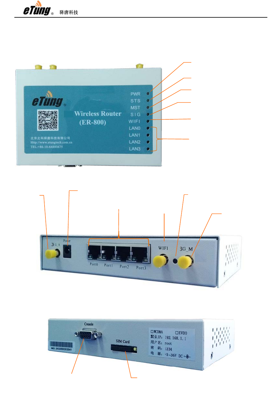
1.2 Product Outlook
Figure 1-1: ER-800 front view
Figure 1-2: ER-800 side view 1
Figure 1-3: ER-800 side view 2
Console Serial Port SIM Card Slot
3G slave
antenna
LAN0~LAN3
WIFI antenna
Reset to default button
3G master
antenna
Power supply
Power li
g
ht
Network status light
Model status li
g
ht
Si
g
nal li
g
ht
WIFI light
LAN port li
g
hts
ER-800 User Manual
6
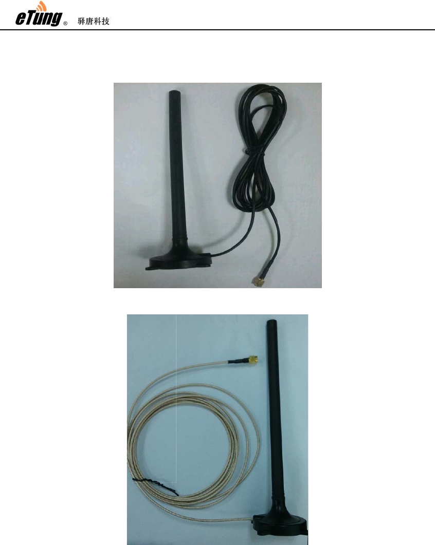
1.3 Standard Accessories
Figure 1-4: 3G all frequency sucking antenna
Figure 1-5: WIFI antenna
ER-800 User Manual
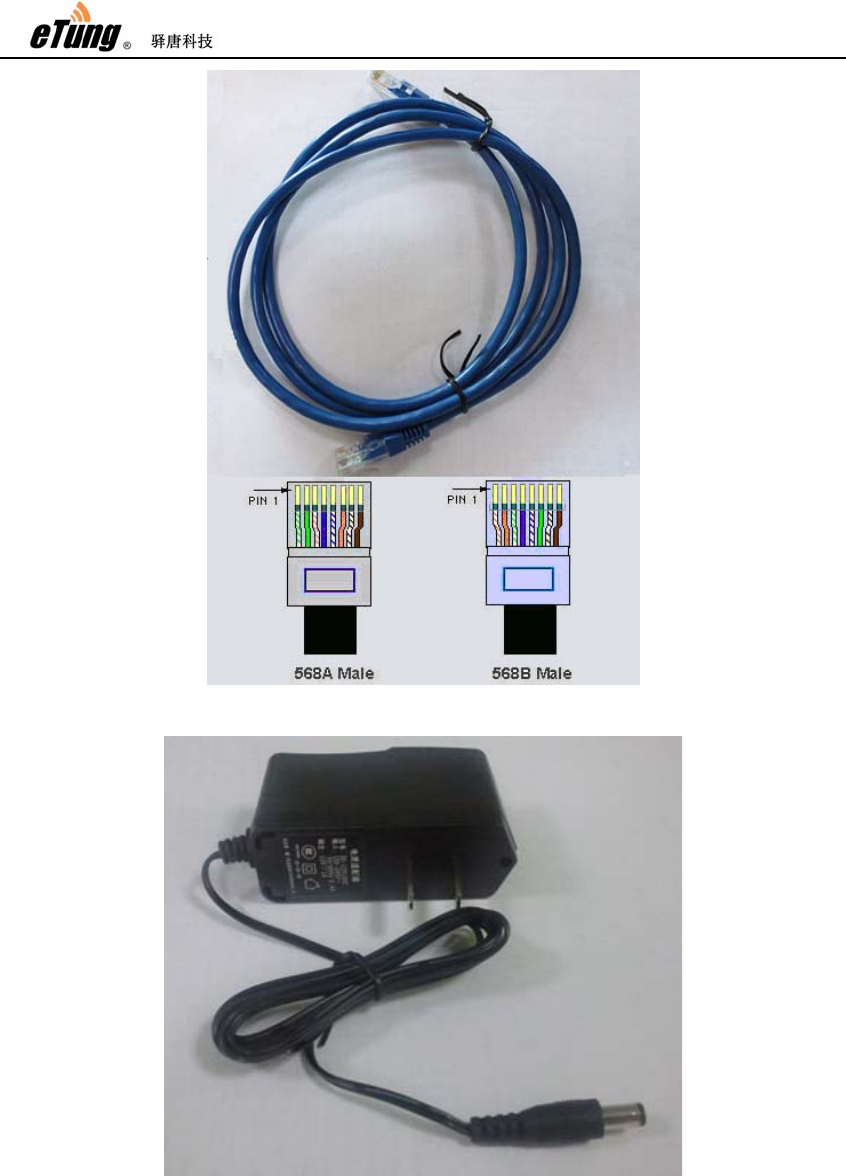
7
Figure 1-6: Cross cable
Figure 1-7: Power supply
ER-800 User Manual
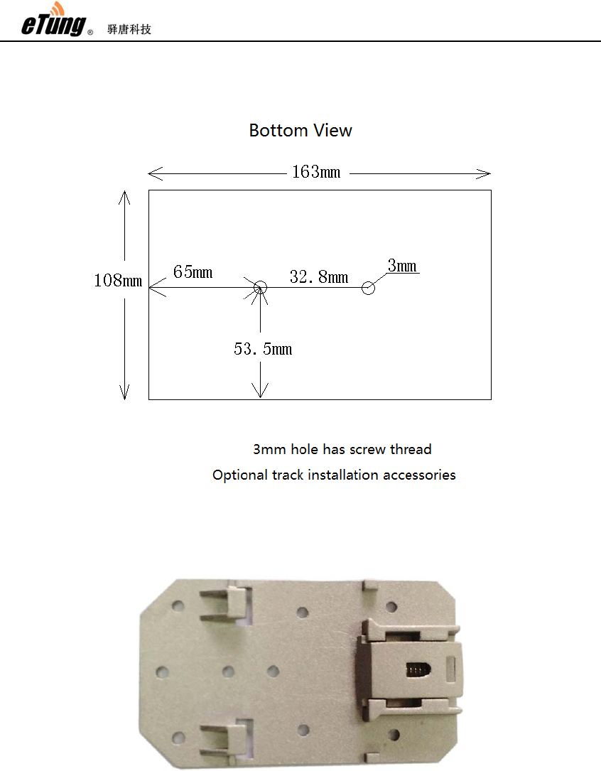
8
1.4 Dimension
Figure 1-8: ER-800 dimension with shell
Currently, ER-800 has two optional installation accessories: orbit type
and flat type, as shown below.
Figure 1-9: Orbit type installation accessory

ER-800 User Manual
9
Figure 1-10: Flat type installation accessory
Using orbit type installation accessory: fix the orbit type installation
accessory on ER-800’s two installation holes with screws, and then
install ER-800 on the orbit of machine room with orbit type accessory.
Figure 1-11: Effect diagram of orbit type installation
Using flat type installation accessory: fix the flat type installation
accessory on ER-800’s two installation holes with screws, and then
install ER-800 with the four installation holes on the installation
accessory.

ER-800 User Manual
10
Figure 1-12: Dimension of flat type installation accessory
Figure 1-13: Effect diagram of flat type installation
ER-800 User Manual
11
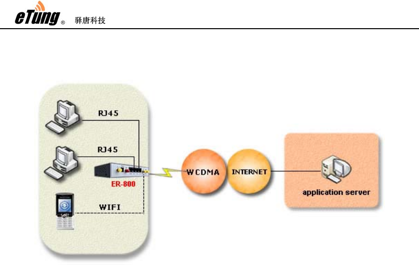
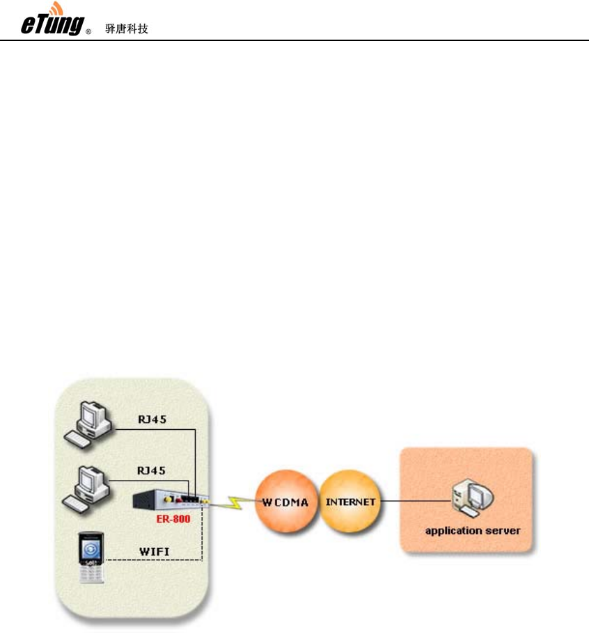
1.5 Working Mechanism
Figure 1-14: ER-800 working mechanism
PC connects to one of ER-800’s Ethernet interfaces with a cross cable.
After power on it dials via 3G wireless network and connects to the
internet, then PCs can share the internet via ER-800, and access the
application server. At the same time, using ER-800’s WIFI
functionality, PCs (or other devices that support WIFI) can connect to
ER-800’s WIFI access point, instead of connecting with Ethernet cable,
to share the Internet access. Meanwhile, ER-800 can be used to build
remote virtual LAN with Virhub or VPN, monitor video remotely, and
publish programs remotely on LED color screens, etc.
1.6 Specifications
1.6.1 Technical Parameters
Basic Parameters
Power Supply: +9 ~ +36V wide range of voltage input
Power Connector: inner(+) outer(-)
Data Interface: 4 RJ45 Ethernet interfaces
Network: GSM/GPRS/EDGE/WCDMA/HSDPA/HSUPA/WIFI
Memory: RAM 64M FLASH 4M
Frequency: UMTS/HSDPA/HSDPA850/900/1900/2100MHz
Quad-BandGSM850/900/1800/1900MHz
WIFI 802.11 b/g/n 2.4GHz

ER-800 User Manual
12
Max Current: 700mA@+5V DC, 300mA@+12V DC
Standby Current: 560mA@+5V DC, 180mA@+12V DC
Temperature: -30ºC ~ +70ºC
Humidity: 95%@+40ºC
Dimension: 165*108*33mm
Basic Functions
Support NAT
Support DHCP server
Support DNS Proxy
Support port forwarding
Support DMZ host(IP address mapping)
Support VPN
Support dynamic domain auto-registration
Support configuring static route table
Support real-time speed display of wireless network
Support configuring with telnet and web interface
Support flow wakeup, phone wakeup and SMS wakeup
1.6.2 Indicator Light Description
LED Indicator
Light Color
Status Description
Power light
(PWR) Red Always light Device is working
Extinguished Device is not working
Online light
(STS) Green
Always light Connected to 3G network
Extinguished No connection to 3G network
Module light
(MST) Red Flashing Module is working
Extinguished Module is not working
Signal light
(SIG) Green
Always light Signal is excellent
Yellow
Signal is good
Red Signal is bad
N/A Extinguished No signal
WIFI Green
Always light WIFI enabled
Extinguished WIFI disabled
Ethernet light
(LAN0-LAN3) Red Always light Ethernet connection OK
Flashing Data transferring
Extinguished Ethernet connection not OK
Table 1-1 ER-800 indicator light description

ER-800 User Manual
13
1.7 Technical Advantages
eTung 3G router takes the leading role in the industry not only from
hardware industrialization, design rationality, software convenience
and usage flexibility, but also from its reliability. Its technical
advantages are easy to see:
Support dynamic domain auto-registration, domain resolving
software is not needed;
Support Telnet and web configuration;
Support 4 RJ45 Ethernet interfaces, at most 4 PCs(devices) can
connect with it via Ethernet cable;
Support WIFI access point, devices supporting WIFI can connect
with it quickly to build a small LAN;
Support VPN to build virtual LAN, and simply change fixed line to
wireless line;
Support configuring 3G router remotely via SMS and from server
side;
Support soft and hard watch dog, keep alive all the time;
Support APN name auto adaption, adaptive universally with default
configuration;
Support LBS location function to check device location at any time;
Support "eYun" platform, server building not needed and
plug-and-play.
ER-800 User Manual
14
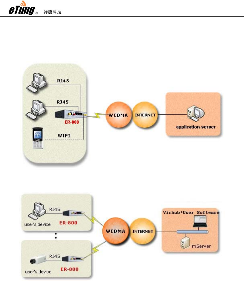
1.8 Typical Usecases
Figure 1-15: Access Internet via 3G router
Figure 1-16: Implement virtual LAN via ER-800’s Virhub functionality
ER-800 User Manual
15
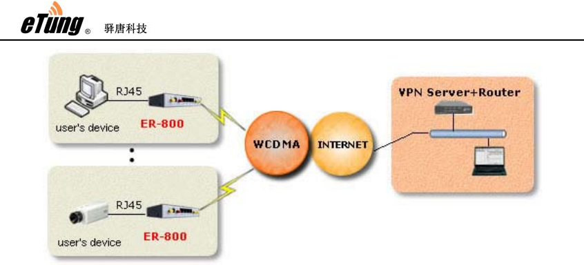
Figure 1-17: Use ER-800 to access LAN remotely via VPN

ER-800 User Manual
16
2. Device Configurations
This chapter introduces how to use ER-800 and related parameters.
1. Configurations
2. Parameters
3. Restore to default
4. Firmware Update
5. Remote Configurations
2.1 Configurations
2.1.1 Preparation
One cross Ethernet cable used to connect ER-800 with PC or
customer device;
One 3G all frequency sucking antenna;
One power supply;
One USIM card (for example China Unicom wo), that can access
internet.
2.1.2 Configuring ER-800
Connect PC with one of ER-800’s Ethernet interfaces via a cross
Ethernet cable;
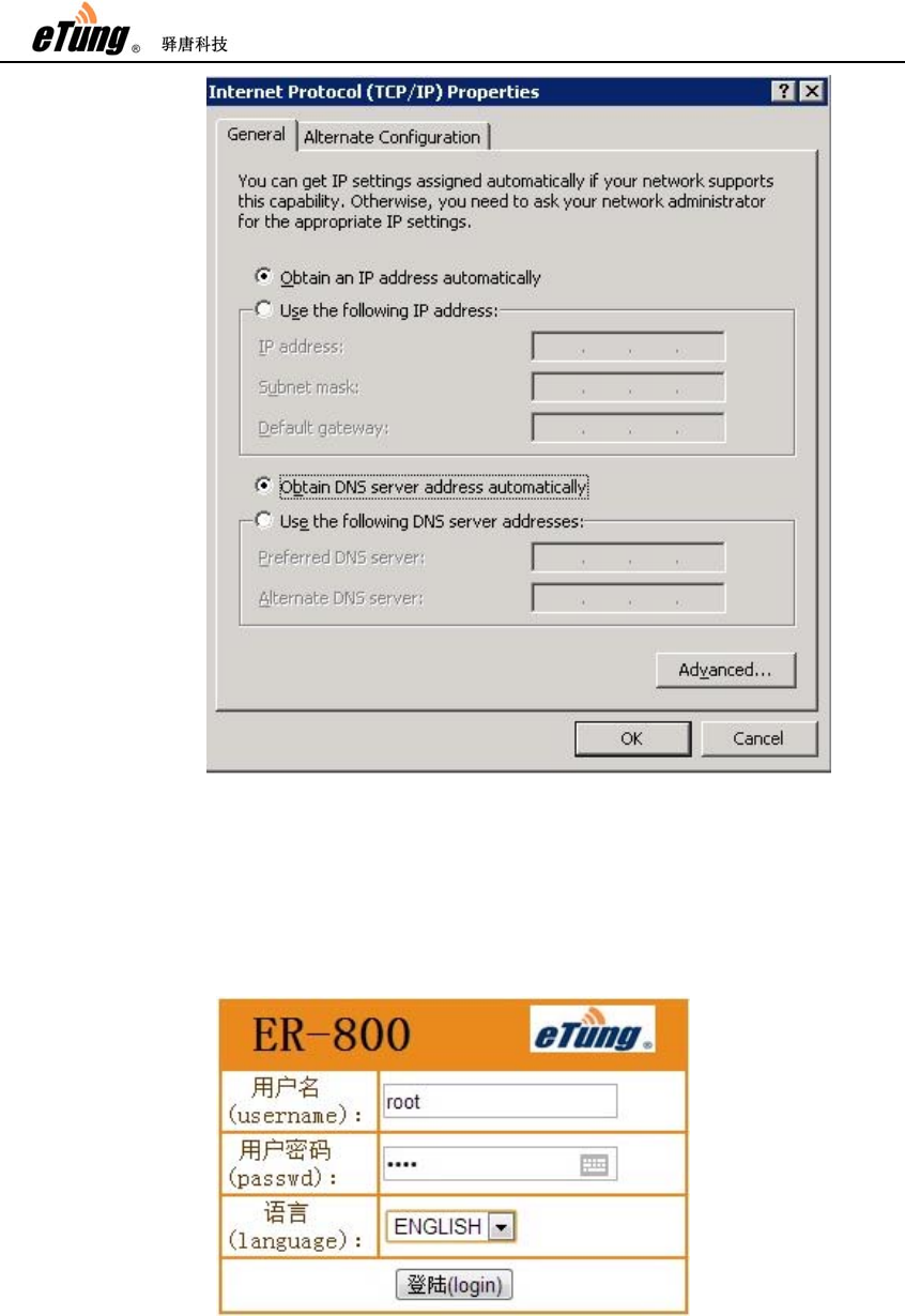
Boot PC, and set IP address as "Automatically obtain IP
address";
ER-800 User Manual
17
ER-800 User Manual
18
Figure 2-1: Set IP address as "Automatically obtain IP address"
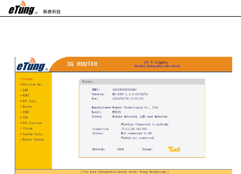
Open IE browser, input address "http://192.168.1.1" and press
Enter;
Input "root" as username and "1234" as password, select
language as “ENGLISH”, then press Enter to login web
configuration interface and configure the device.
Figure 2-2: Login router configuration interface
ER-800 User Manual
19
It is clear to see each configuration item in the router
configuration interface. To change some parameter, click it,
modify and then save it, then reboot the router. Keep the
default configurations if the router is used only to access
internet.
Figure 2-3: Router's current status

ER-800 User Manual
20
2.2 Configuration Parameters
Each configuration menu has multiple parameters, and some of them
have sub-menus. Details are described below.
Configuration Menu Item Description
Current status Show device information, connection
and data transfer status.
Wireless Net Simple Cfg Set user information about dialing into
internet and SMS function, normally
with default value
Advanced Cfg Check network debugging information
LAN Set the router IP of LAN and set the
DHCP function
WIFI
Configure WIFI parameters, normally
with default values (Enable WIFI, SSID
is “ER-800”, enable security and with
PSK PIN “12345678”).
NAT Rule
NAT Whether the device connected with
router can access internet via NAT.
Port Mapping Use pre-defined port to forward data
from internet to some inner IP's
dedicated port.
DMZ Host Forward data from internet directly to
some inner IP.
Router Set up static router table, a maximum of
10.
DDNS Domain resolving function, configure
the router to have a static domain to be
easily accessed.
VPN PPTP&L2TP Login with username and password to
connect VPN
GRE Set Set routing data encapsulation mode,
normally with default value.
DTU
Function
Simple Cfg Set master data center address and
serial port parameters
Advanced Cfg Set standby data center address and
data format
Link Management Set heart beat parameters, normally
with default values
Embedded DC Set embedded data center function
Proxy Client Set proxy client address
Virhub Set server address for Virhub function,
with eYun platform as default

ER-800 User Manual
21
System
Tools
System Set Set router's communication parameters,
normally with default values
SNMP Set Set SNMP parameters, normally with
default values
System Log Show router's connection and
communication logs
DTU Log Show router's data transfer logs with
DTU function
Restore Set Restore to initial default settings with
one key
Upgrade Firmware Update router's firmware
Change Password Change password logging router(1234
by default)
Import/Export config
Import parameter file saved
before/Export current configurations to
file
Reboot System Reboot router
Table 2-1: Details of configuration parameters
2.3 Restore to Default
According to the description of "Configuring ER-800", after entering
ER-800 configuration interface, select "System Tools" and then
"Restore Set".
Figure 2-4: Restore to default

ER-800 User Manual
22
This can also be done by using the button “Reset to default” on ER-800.
After ER-800 is started, hold the button “Reset to default” with a sharp
object, do not release the button until “Online light” flashes two or
three times and then always lights, that means the router has been
reset to default and is rebooting automatically.
ER-800 User Manual
23
2.4 Firmware Update
Ask eTung for firmware software
According to the description of "Configuring ER-800", connect
ER-800 with PC via a cross Ethernet cable, input username and
password (by default username is root and password is 1234), and
login router configuration interface.
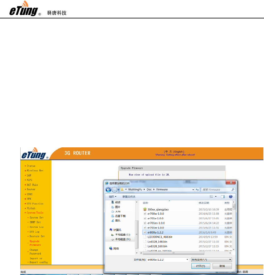
Select "System Tools" and then "Upgrade Firmware", click "Browse",
select the file (.img) to update, and click "Open", then click
"Upload".
Figure 2-5: Select file to update
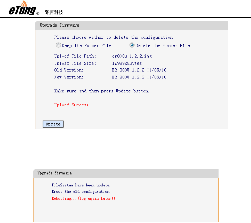
Click "Update" after upload is complete.(It's better to select "Delete
the Former File")
ER-800 User Manual
24
Figure 2-6: Firmware Update
After update is complete the device will reboot automatically, and it
will show as in the figure below.
Figure 2-7: Update complete

ER-800 User Manual
25
2.5 Remote Configurations
SMS commands and remote AT commands can be used on ER-800 to
modify configuration parameters remotely. Details are described
below:
1. Modify configuration parameters remotely via SMS
The SMS to configure ER-800 parameters should follow the format
below: SMS password;AT commands
1) SMS password is the "SMS wakeup password" as shown in
wireless network settings of the web configuration interface,
with "1234" by default. This password is used to filter rubbish
SMS. Long SMS is not supported.
2) There can be multiple AT commands, and ";" is used between
SMS and AT command, and between AT commands. If there are
more than one AT command and some command fails, the
following commands will not be executed. If a command is
unknown, an ERROR will return. The commands will take effect
after system reboot. This can be done by putting a command
"AT+REBOOT" in the end of SMS commands, or sending a
separate SMS with command "AT+REBOOT".
3) AT command must be capitalized, but the parameters in the
command do not have this limit.
4) If there are multiple parameters in the command, just write
those that need to change and you do not have to write all of
them. If some item does not need to change, write two
continuous colons, and if some item needs to clean, write a
space. For example:
AT+WN=3gnet (configure onely APN, and other parameters keep
unchanged)
AT+DC=,,user (the first two items keep unchanged, and change
username only)
For remote SMS configuration, the contents of SMS must be English
charactes or digits in single byte, and can not be in double byte.

ER-800 User Manual
26
AT commands that can be used via SMS are listed and described
below:
1) AT+WN=apn,user,passwd,net_mode
Configure parameters related to dialling, with reply OK or ERROR.
apn: Access point name, this parameter is unused for EVDO device
and can be null. write "auto" to ask to select APN automatically.
user: dialling account, the dialing password must be changed
together with dialling account.
passwd: dialling password, the dialing account must be changed
together with dialling password.
net_mode: network mode: 1(GSM only), 2(WCDMA only),
3(GSM/WCDMA auto selection, WCDMA preferred)
2) AT+DC=addr,port,user,mode
Configure data center parameters, with reply OK or ERROR.
addr: data center address, either IP or domain
port: data center port
user: username
mode: TCP or UDP
3) AT+PWD=passwd
Set new SMS password, with at most 8 characters, exluding ",",":",
"=", etc. It is adviced to use digits and English characters only. The
reply is OK or ERROR.
4) AT+VIRHUB=0/1
Set whether to enabe Virhub or not, with reply OK or ERROR.
0: disable Virhub, 1: enable Virhub
5) AT+RESTORE
Restore to default settings, with reply OK.
6) AT+REBOOT
Reboot the device, with reply OK.
7) AT+STATUS?
Check current status, with reply below:
OK:connection status,signal quality,IP address,net_mode
connection status: 0: dialling not successful, 1: dialling successful
signal quality: 0-31, bigger value means better quality
IP address: IP address obtained after dialling is successful, invalid
if dialling is not successful.
net_mode:GPRS/EDGE/WCDMA/HSDPA/HSUPA/HSPA/HSPA+
8) AT+WN?
Check wireless network settings, with reply below:
OK:addr,port,user,mode
Refer the first command for parameters description

ER-800 User Manual
27
9) AT+DC?
Check data center parameters, with reply below:
OK:addr,port,user,mode
Refer the second command for parameters description
10) AT+PWD?
Check SMS password, with reply below:
OK:passwd
11) AT+INFO?
Check device information. with reply below:
OK:IMEI,version,IP address at Ethernet interface
12) AT+VIRHUB?
Check status of Virhub, with reply below:
OK:0/1
0: Virhub is disabled, 1: Virhub is enabled.
13) AT+UPDATE=url
Update firmware, with reply OK or ERROR. The reply OK does not
mean update is complete, but the command has been received and
the update will start. To check whether update is successful, send
AT+INFO? after 5 minutes and check whether the firmware version
is changed.
url: download URL of the new firmware, beginning with "http://".
Make sure the device can access this url, for example it should not
be a public URL if the device has a private net card.
14) AT+UPDATEALL=url
Update firmware and restore to default settings, with reply OK or
ERROR.
url: download URL of the new firmware, beginning with "http://".
Make sure the device can access this url.
15) AT+SMSZHUANFA=txt,info_src,dest
Ask the router to send an SMS to info_src first with content “txt”
(only in English characters and digits), and then forward the reply
to dest. dest can be omitted, and if then the reply will be forwarded
the the mobile that sends this AT command. If the reply SMS has
more than one message, the router will forward the messages one
by one.
For example: AT+SMSZHUANFA=CXLL,10086,13801234567,
means to send an SMS to 10086 to query traffic and then forward
the reply to 13801234567.
2. Change configuration parameters via remote AT commands
1) This method can be used only when enabliing DTU function or
virhub function, and ER-800 is shown online in mServer.
2) Method: choose the router in mServer’s console, right-click it and
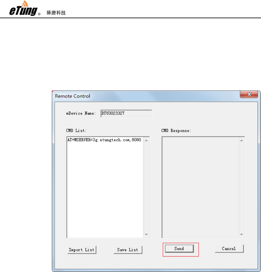
ER-800 User Manual
28
choose “Remote Control”, in the popped-up dialog, input AT
commands in “CMD List” on the left side.
For example, input the following command to change the data
center’s address and port:
AT+MSERVER=3g.etungtech.com,8080
Click “Send” afterwards, and if successful, a “OK” will show in
“CMD Response” on the right side. Then ER-800 will be offline from
the original mServer, and connect to the new data center and port.
Remote AT commands are listed below:
1) AT
2) AT+MSERVER=addr, port
Change data center address and port, with reply OK or ERROR.
addr: data center address, either IP address or domain
port: data center port
3) AT+USER=user
Change DTU username, with reply OK or ERROR.
user:username
4) AT+CSQ
Query signal strength and network mode, with the following
reply:

ER-800 User Manual
29
OK:sig_quality,net_mode
sig_quality: 0-31, bigger value means better signal quality
net_mode:
GPRS/EDGE/WCDMA/HSDPA/HSUPA/HSPA/HSPA+
5) AT+REBOOT
Reboot the router, with reply OK.
6) AT+UPDATE=url,md5
Update firmware, with reply OK or ERROR. The reply OK does
not mean update is complete, but the command has been
received and the update will start. To check whether update is
successful, send AT+INFO? after 5 minutes and check whether
the firmware version is changed.
url: download URL of the new firmware, beginning with
"http://". Make sure the device can access this url, for example
it should not be a public URL if the device has a private net
card.
7) AT+UPDATEALL=url,md5
Update firmware and restore to default settings, with reply OK
or ERROR.
url: download URL of the new firmware, beginning with
"http://". Make sure the device can access this url.
8) AT+DTU&IMEI?
Query the router’s IMEI number, with the following reply:
OK:IMEI
9) AT+DTU&VER?
Query the router’s version, with the following reply:
OK:ver
10) AT+CM&TYPE?
Query protocol type, with the following reply:
OK:prot
Prot: TCP, UDP or ETCP
11) AT+CM&HBI?
Query heartbeat interval, with the following reply:
OK:interval
Heartbeat interval is in seconds.
12) AT+CM&HBT?
Query heartbeat timeout, with the following reply:
OK:timeout
Heartbeat timeout is in seconds.
13) AT+SER&BAUD?
Query user serial port baud rate, with the following reply:

ER-800 User Manual
30
OK:baud
Baud: 2400/4800/9600/19200/38400/57600/115200
14) AT+SER&SIZE?
Query user serial port data bits, with the following reply:
OK:size
size: 8/7/6/5
15) AT+SER&PAR?
Query user serial port parity, with the following reply:
OK:par
Par: N: no parity, O: odd parity, E: even parity
16) AT+VIRHUB&ENABLED?
Query whether virhub function is enabled, with the following
reply:
OK:0/1
0: disable virhub function, 1: enable virhub function
17) AT+CM&TYPE=prot
Set protocol type, with reply OK.
prot:TCP、UDP、ETCP
18) AT+CM&HBI=interval
Set heartbeat interval in seconds, with reply OK.
19) AT+CM&HBT=timeout
Set heartbeat timeout in seconds, with reply OK.
20) AT+SER&BAUD=baud
Set user serial port baud rate, with reply OK.
Baud: 2400/4800/9600/19200/38400/57600/115200
21) AT+SER&SIZE=size
Set user serial port data bit, with reply OK.
Size: 8/7/6/5
22) AT+SER&PAR=par
Set user serial port parity, with reply OK.
par: N: no parity, O: odd parity, E: even parity
23) AT+VIRHUB&ENABLED=0/1
Enable/disable virhub function, with reply OK.
24) AT+SMSPING=PHONE_NUM
Ask the router to send an SMS to PHONE_NUM, and the
content is the router’s IMEI number, with reply OK.
25) AT+SMSZHUANFA=txt,info_src,dest
Ask the router to send an SMS to info_src first with content

ER-800 User Manual
31
“txt” (only in English characters and digits), and then forward
the reply to dest. dest can be omitted, and if then the reply will
be forwarded to the mobile that sends this AT command. If the
reply SMS has more than one message, the router will forward
the messages one by one.
For example: AT+SMSZHUANFA=CXLL,10086,13801234567,
means to send an SMS to 10086 to query traffic and then
forward the reply to 13801234567.
26) AT+VIRHUB&TAP_IP?
Check the remote access IP address via Virhub, with reply:
OK:x.x.x.x
27) AT+VIRHUB&TAP_MASK?
Check the remote access netmask via Virhub, with reply:
OK:x.x.x.x
28) AT+VIRHUB&TAP_IP=x.x.x.x
Set the remote access IP address via Virhub, with reply OK.
29) AT+VIRHUB&TAP_MASK=x.x.x.x
Set the remote access netmask via Virhub, with reply OK.
ER-800 User Manual
32
Appendix 1: Configure ER-800 for
High-Speed Internet Connection
PC can be directly connected to one of ER-800's Ethernet interfaces to access
internet wirelessly, and mobile phones or other devices that has enabled WIFI can
connect to ER-800 via WIFI, and share the Internet access.
Figure Appendix 1-1: PC accesses internet via ER-800
Steps:
(1) Connect PC with one of ER-800’s Ethernet interfaces via a cross Ethernet
cable;
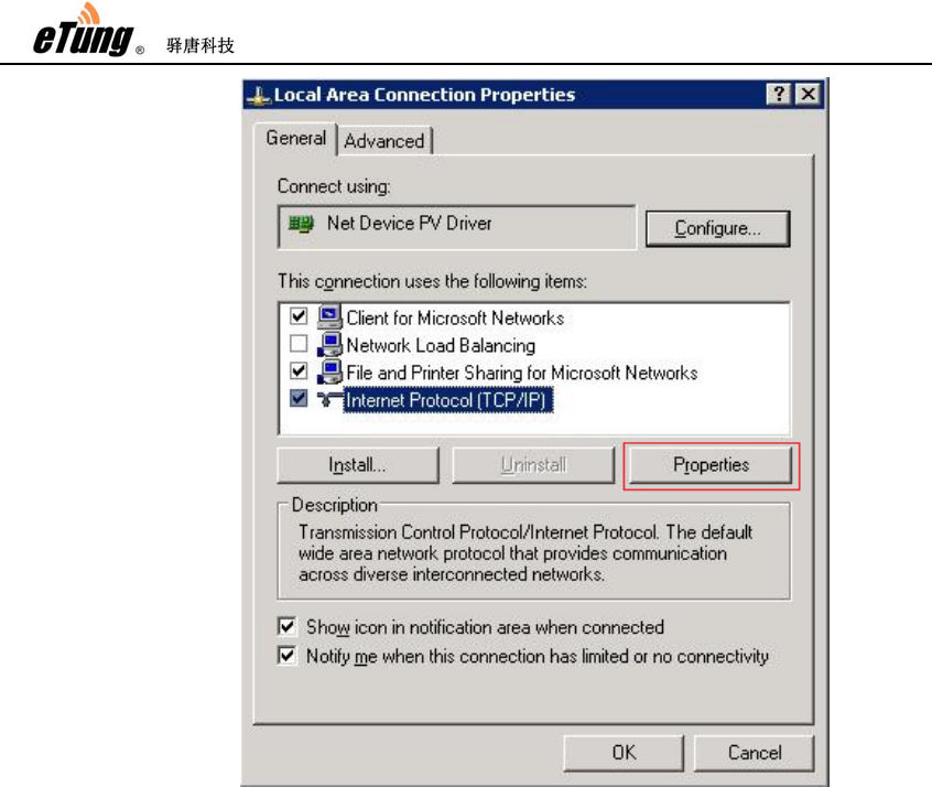
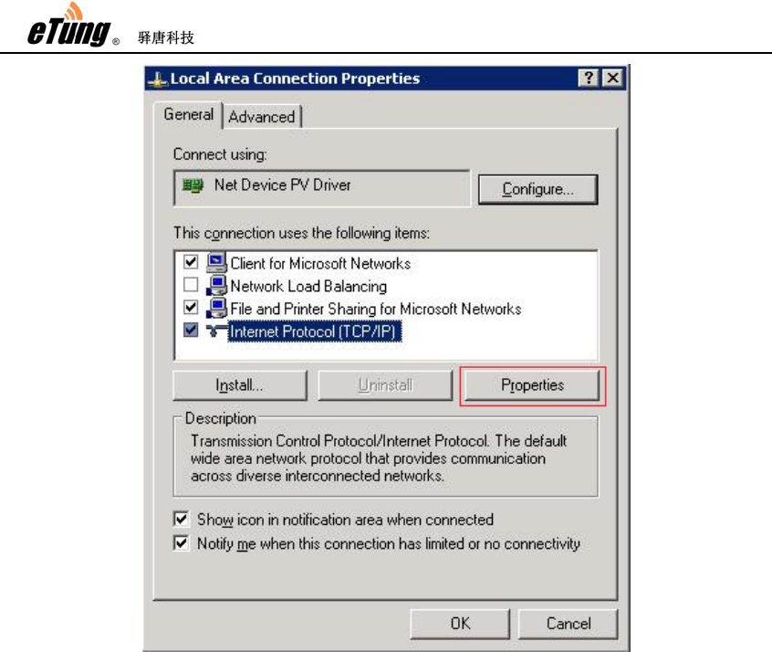
(2) Configure IP on PC as "Automatically obtain IP address":
Click "Control Panel"->"Network Connection"->"Local Connection", then
right-click "Local Connection" and select "Properties"
ER-800 User Manual
33
ER-800 User Manual
34
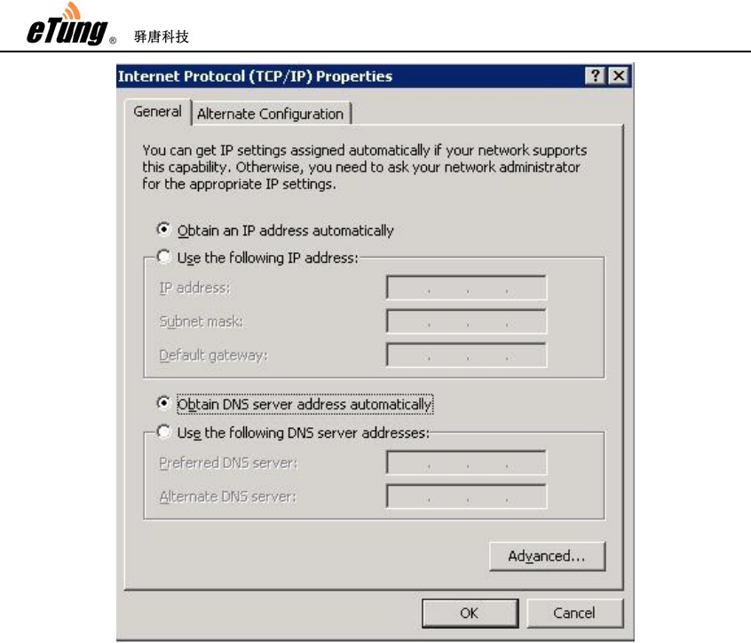
Figure Appendix 1-2: Configure to obtain IP address automatically
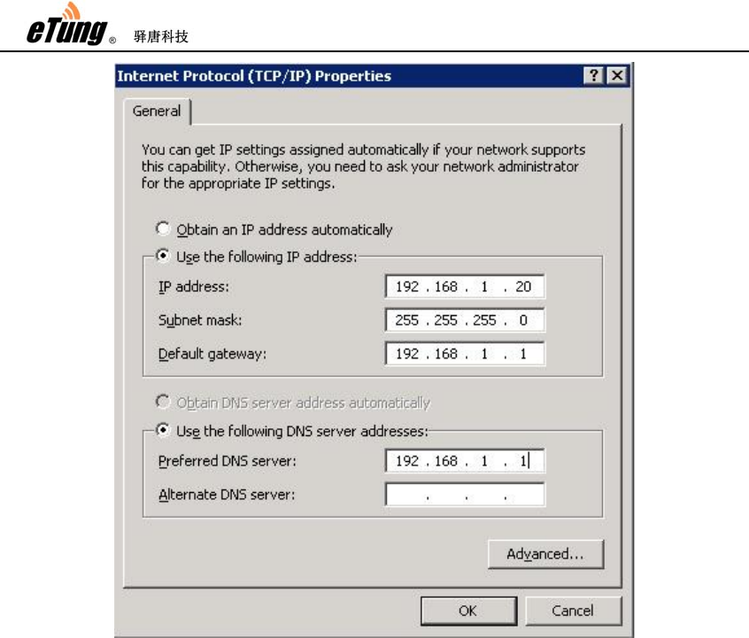
Or: you can configure a static IP address. Pay attention, the default
gateway of ER-800 is 192.168.1.1, the IP address set manually should be
in the same range (192.168.1.2~192.168.1.254), for example,
192.168.1.20 as shown below:
ER-800 User Manual
35
Figure Appendix 1-3: Configure a static IP address manually
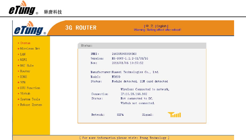
(3) Plug a WCDMA card into ER-800, then after power on, ER-800 will dial
automatically; and after dialing is successful, you can browse webpage,
and send/receive emails via PC. The dialing status of ER-800 can be
checked in the web interface. Just input http://192.168.1.1(ER-800's
default gateway is 192.168.1.1) in IE, then input default username root,
and password 1234, you can then check the working status, as well as
current connection speed and flow of ER-800.
ER-800 User Manual
36
Figure Appendix 1-4: 3G router's network connection status
ER-800 wireless router has functions such as port forwarding, DMZ host, and
DHCP service, so customers can define data forwarding rules on ER-800 as
on a generic router.
ER-800 User Manual
37
Appendix 2: eYun Virhub Testing
Case
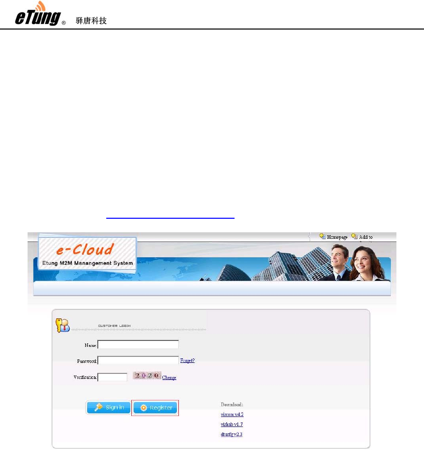
1. Apply eYun account
Access website http://3g.etungtech.com, apply a Virhub eYun account, and
then contact technical support to open this account.
Figure Appendix 2-1: Apply eYun account
2. Configure Virhub parameters
Refer chapter 2 Configuration, enter Virhub configuration menu, and select
Virhub; input the username applied above, and click "Save", then reboot
the router.
ER-800 User Manual
38
Figure Appendix 2-2: Enable Virhub function
3. Install Virhub software
Ask wireless Virhub v5.x installation package from eTung, install it
according to Virhub’s installation guide.
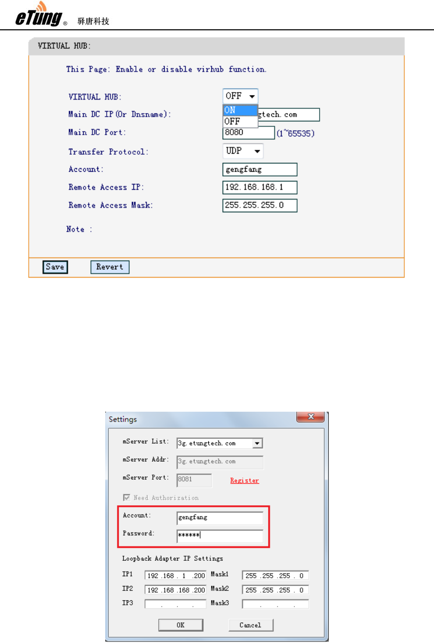
4. Login in Virhub and start data transfer
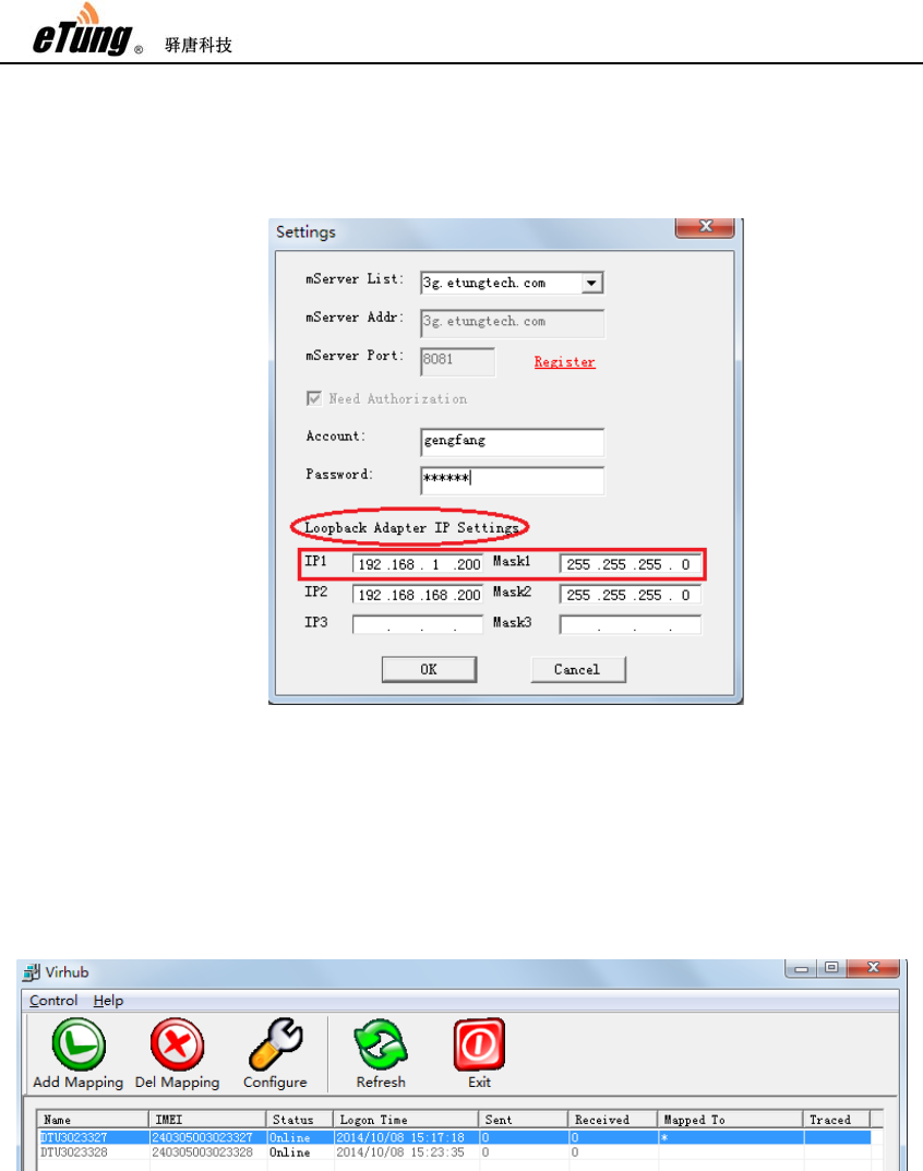
1) Run Virhub and click "Settings", input the username and password
applied before.
Figure Appendix 2-3: Login Virhub
ER-800 User Manual
39
2) Configure Microsoft Loopback adapter’s IP address: in the “Settings”
dialog, we can set Loopback adapter’s IP address in “Loopback Adapter
IP Settings”. IP1 is used to build a virtual LAN with the front-end device
(i.e. the Webcam), and it has to be in the same IP range as the
front-end device’s IP, for example, 192.168.1.*.
Figure Appendix 2-4: Configure Loopback adapter’s IP address
Press “OK” after configuration, the software will set the IP address to
the Loopback adapter.
3) Find the device to be tested based on IMEI, click "Add" to add user PC to
the virtual LAN of "Customer Device - ER-800 - User PC", then the user
PC can communicate directly with the customer device.
Figure Appendix 2-5: Add Virhub PC to virtual LAN
5. Access the wireless router remotely via Virhub
ER-800 V1.0.6 or higher version has functionality of accessing the wireless
router remotely via Virhub. Normally, the router dials up into the wireless
network and gets an inner IP address, and it cannot be accessed from the
internet via this inner IP. eTung’s Virhub solution can solve the problem.
First, enable Virhub function on the router, and set a remote access IP; the
ER-800 User Manual
40
remote access IP is dedicated to access the router remotely when Virhub is
enabled on the router. Then run Virhub software on the far-end PC, and
configure an IP address on the Loopback adapter; this IP must be in the
same range as the remote access IP on the router. This way, we can access
the router remotely on the far-end PC via the remote access IP, to perform
configuration, system monitoring, etc. Below are the details about the
configuration procedure.
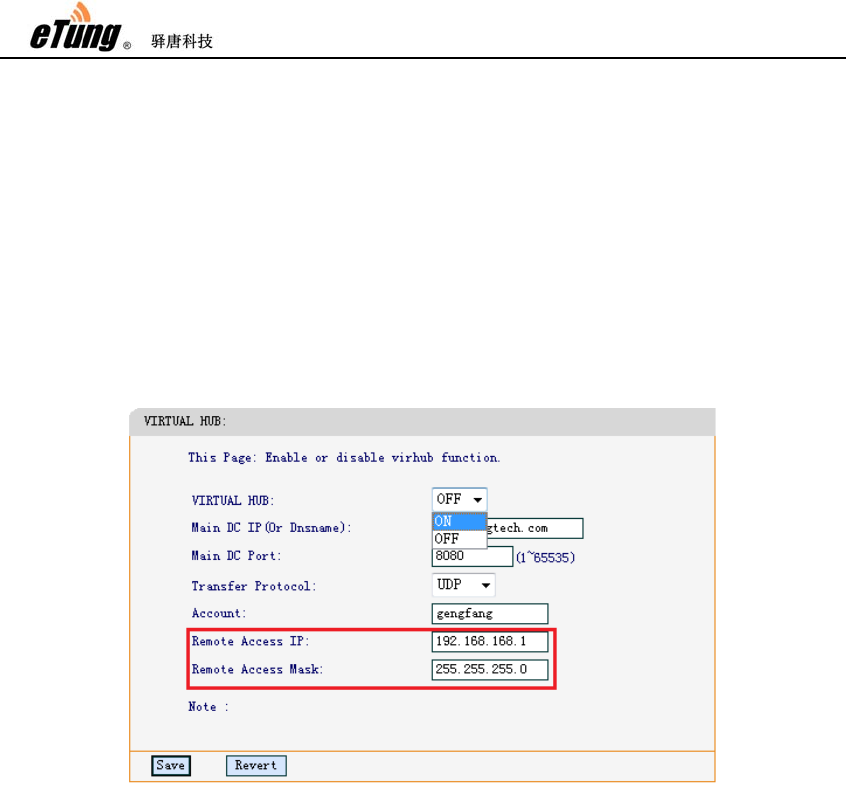
1) Configure the router’s remote access IP
According to “2. Configure Virhub Parameters”, go to the router’s
Virhub configuration, enable Virhub and configure username, then
there are two parameters: “Remote Access IP” and “Remote Access
Mask”, with default values: 192.168.168.1 and 255.255.255.0.
Figure Appendix 2-6: Configure the router’s remote access IP
Normally set the two parameters with default values, and they can also
be changed on demand. Press “Save” after configuration, then reboot
the router. These two parameters can also be changed/checked via
remote AT commands, please refer “2.5 Remote Configurations”.
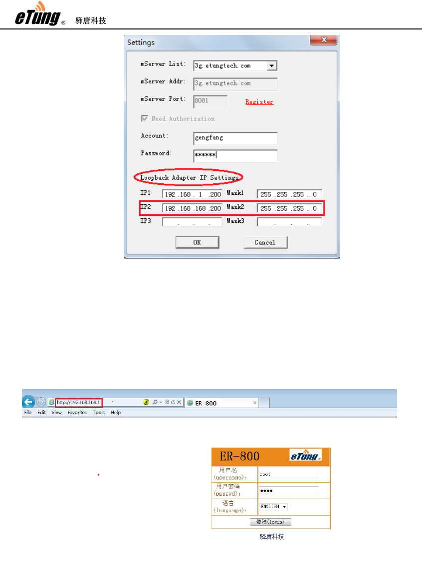
2) Configure the Loopback adapter’s IP address to access the router
remotely
Run Virhub software, click button “Configure”, and on the popped up
“Settings” dialog, set the Loopback adapter’s IP address in “Loopback
Adapter IP Settings” part. IP2 is the IP address set on the Loopback
adapter to access the router remotely via Virhub, and this IP must be in
the same range as the “Remote Access IP” (192.168.168.1 by default)
set on the router in step 1), for example, 192.168.168.*.
ER-800 User Manual
41
Figure Appendix 2-7: Configure the Loopback adapter’s IP address to
access the router remotely
Click “OK” after configuration is complete, the software will then set the
IP address on the Loopback adapter.
3) Access the router remotely
Open browser, and input the router’s remote access IP (192.168.168.1
by default), and then the router’s web configuration page shows.
Figure Appendix 2-8: Access the router’s Web configuration page
remotely
Then we can login the web page to change the router’s parameters
remotely, just as the router is directly connected locally.

ER-800 User Manual
42
Appendix 3: APN Network Testing
Case
APN is the abbreviation of Access Point Name. It is used in operators’ core network
to identify the external data network, for example, enterprise intranet, Internet,
WAP website and enterprise’ internal networks. Using the APN SIM card, the
terminal dials up into a dedicated network predefined from the operator side, and
normally gets an internal IP address to access the network, this IP address cannot
be accessed from the internet. But the terminals that dial into the same dedicated
network can access each other. So we can easily implement the interconnection
between wireless terminals with operator’s APN networks, it’s very convenient and
can greatly reduce network access cost. There are two kinds of solutions to use APN
networks, and below are details for each of them.
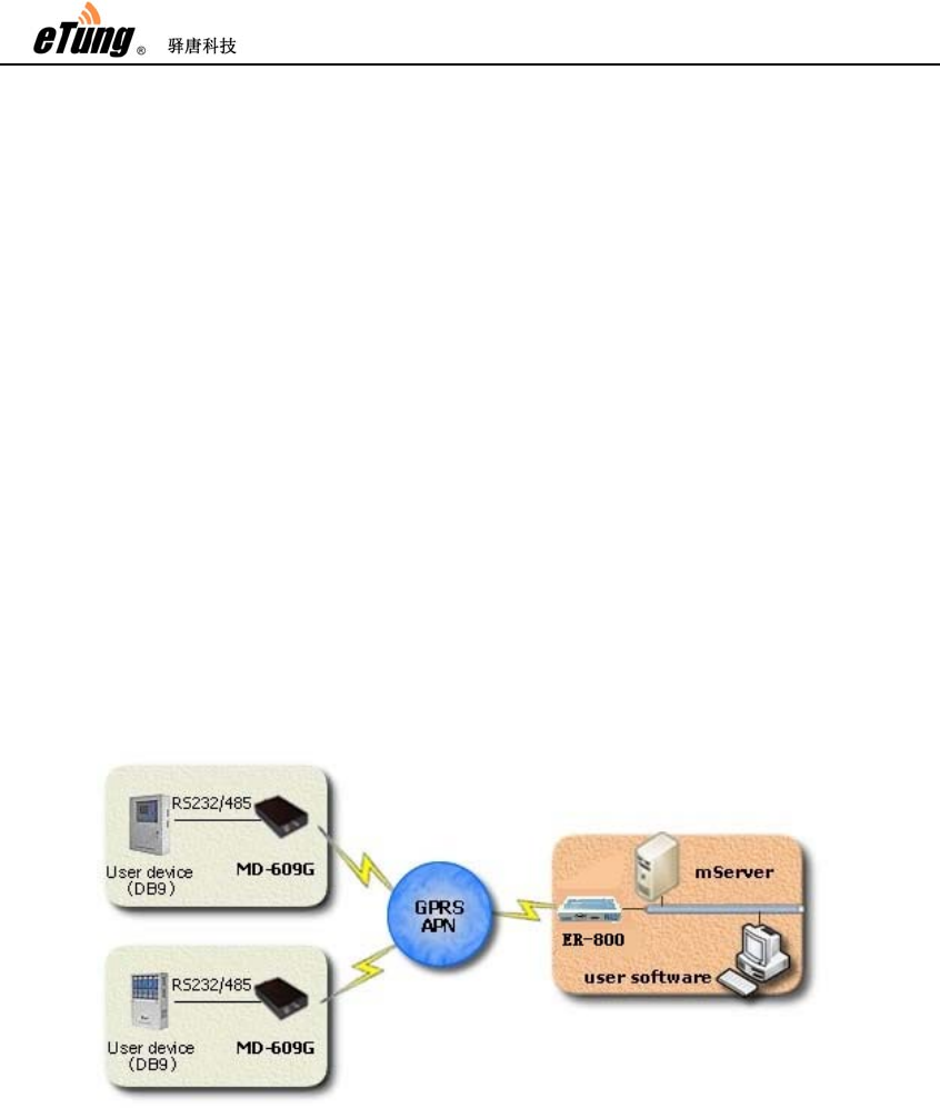
Solution 1: Embedded Data Center with APN Network
eTung’s wireless routers support APN SIM card, and has embedded data center
function. For those small-scale projects with few terminals, use one router as the
data center, and dial into APN network; at the same time, all other terminals that
connect to devices at the far end dial into the same APN network, then from the
router’s data center we can access the terminals at the far end, thus implement
remote control of devices at the far end. This solution is cost-efficient, and can be
easily deployed; it’s flexible and convenient, and can be used especially in
small-scale (No. of terminals <=100) device control projects.
Figure Appendix 3-1: Embedded data center and APN network solution
Below we will illustrate how to deploy this solution, and use MD-609G as an

ER-800 User Manual
43
example for terminals at the far end.
First of all, please order APN SIM cards from operator, and parameters include APN
name, PPP username and password, and for the SIM card used by the router there
should be a static IP address assigned as well.
1. Configure APN parameters in the router
According to the description of “2.1 Configurations”, login in the configuration
web page, Choose “Wireless Net”->”Simple Cfg”, and then select “Manual Set”
for APN Mode, configure APN name, and PPP username and password if
required. click “Save” and then reboot the router to apply the change.
Figure Appendix 3-2: Configure APN parameters in the router
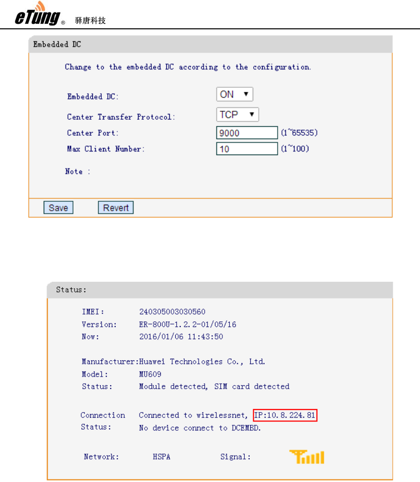
2. Configure Embedded Data Center in the router
Login the router’s configuration web page, choose “DTU
Function”->”Embedded DC”, enable embedded DC, set transport protocol as
TCP, center port as 9000, and set the maximum number of terminals as
required, at most 100, and then click “Save” and reboot the router.
ER-800 User Manual
44
Figure Appendix 3-3: Configure embedded DC in the router
After the router reboots and dials up into the APN network, in configuration web
page “Status”, we can check the IP address assigned by APN network.
Figure Appendix 3-4: Check the IP address acquired from APN network
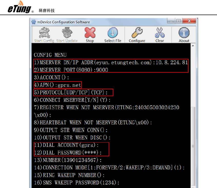
3. Configure data center address and APN parameters in DTU
Run wireless configuration software dtucfg.exe, power on DTU according to the
prompt and then enter the configuration menu. For the 1st item: mServer
DN/IP Addr, set as the static IP address acquired by the router from APN
network, for example, 10.8.224.81; for the 2nd item: mServer Port, set as 9000;
for the 4th item: APN, set as the APN name; for the 5th item: Protocol, set as
TCP that is the same as the transport protocol configured in the embedded data
center; then press Enter until Dial Account and Password, set as PPP username
and password of the APN SIM card as required.
ER-800 User Manual
45
Figure Appendix 3-5: Configure DC address and APN parameters in DTU
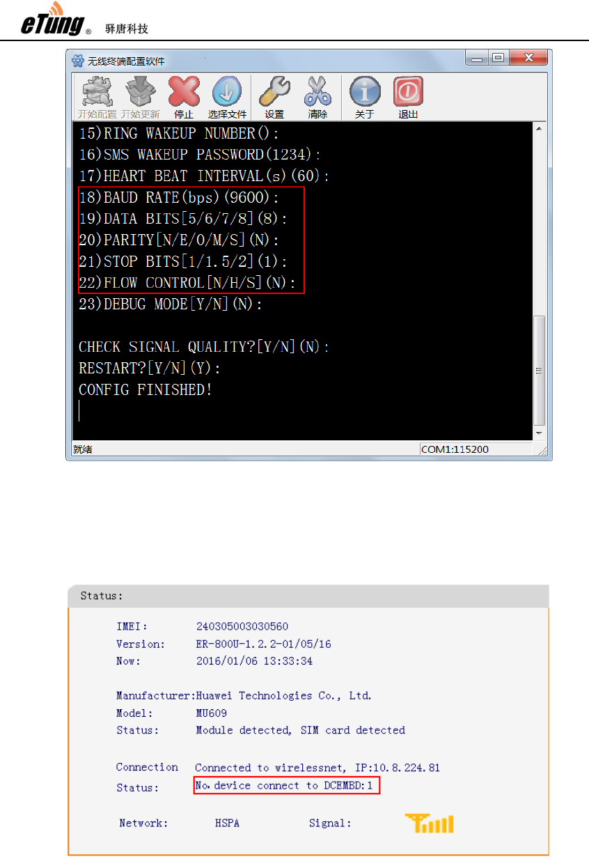
After that press Enter until the serial port parameters: baud rate, data bits,
parity, stop bits and flow control, the values for these parameters must be the
same as those set in the serial device that DTU connects to; and if they are not
the same, we can modify the values here in DTU to make sure they are the
same.
ER-800 User Manual
46
Figure Appendix 3-6: Configure DTU serial port parameters
After configuration is finished, reboot DTU to dial up into APN network, it will
then automatically connect to the router’s embedded data center; in the
router’s status page, we can see that one device has connected the embedded
data center.
Figure Appendix 3-7: Status shows DTU has connected to embedded DC
4. Device at the front end receives/sends data via serial port
ER-800 User Manual
47
After configuring router and DTU at the far end, both dial up into the APN
network, and DTU connects to the embedded data center running in the router;
then we can receive data from the serial device at the far end via the router’s
user serial port, and at the same time device at the front end can send data to
the device at the far end via the router’s user serial port. Pay attention, the
front-end device broadcast data to all the far-end devices, so there should be
identity in the data packets sent/received between front-end and far-end
devices to distinguish from/to whom the packets are received/sent.
Solution 2: mServer Connects the Router and with APN Network
For large-scale projects with lots of terminals, this solution: mServer connects the
router and with APN network can be used. As shown in the figure below, eTung’s
wireless router dials into operator’s APN network, and the data center at the back
end connects to the router with Ethernet cable; at the same time configure DMZ
host on the router, then terminals at the far end dial into the same APN network and
can connect to the data center at the back end. Compared to solution 1, this
solution can also be easily deployed and cost-efficient; at the same time since the
data center is running in a dedicated server, compared to embedded data center
solution, it allows more terminals to connect to the data center, and there can be
more flexible configurations, for example, map a virtual serial port for each
terminal, make point-to-point mapping between two terminals, etc.
Figure Appendix 3-8: mServer connects to the router and with APN network
Below we will illustrate how to deploy this solution, and use MD-609G as an
example for terminals at the far end.
First of all, please order APN SIM cards from operator, and parameters include APN
name, PPP username and password, and for the SIM card used by the router there
should be a static IP address assigned as well.
1. Install and run mServer in the data center server
Ask eTung for mServer installer, and install mServer according the user manual.
Make sure the firewall software allows accessing mServer from outside.
ER-800 User Manual
48
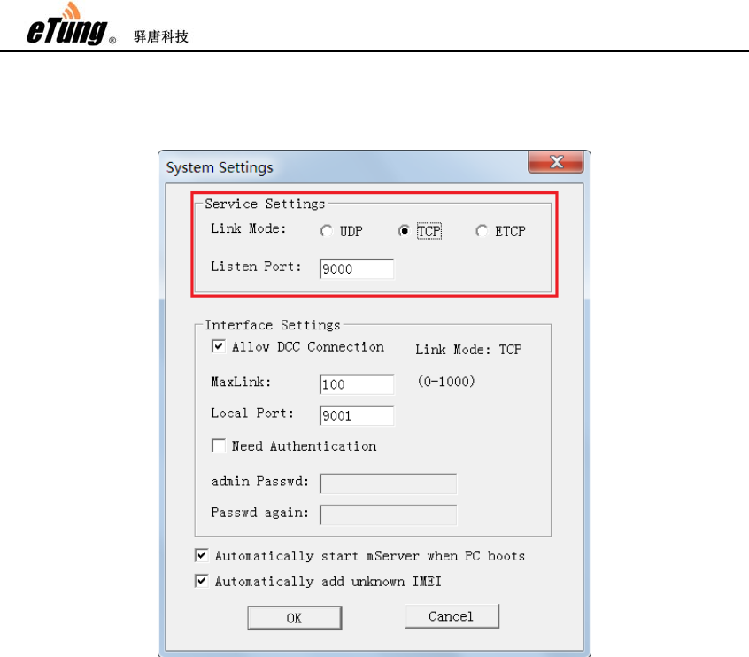
After mServer is installed, double-click mServer’s icon on the desktop to run
mServer console, choose “System Settings”, in tab “Service Settings”, choose
TCP for link mode, and set listen port as 9000.
Figure Appendix 3-9: Configure mServer
2. Configure APN parameters in the router
As step 1 in solution one shows, configure APN parameters in the router’s
configuration web page.
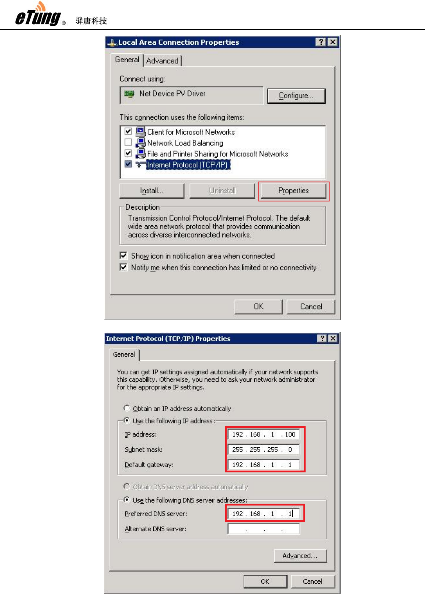
3. Configure DMZ host in the router
First, connect data center server to the router with Ethernet cable.
Then, set static IP address in the data center server, and the IP address must
be in the same IP range as the IP address of the router’s Ethernet interface, for
example, 192.168.1.*. The figure below shows the server’s static IP address is
set to 192,168.1.100, and gateway and DNS are set to 192.168.1.1.
ER-800 User Manual
49
Figure Appendix 3-10: Set static IP address
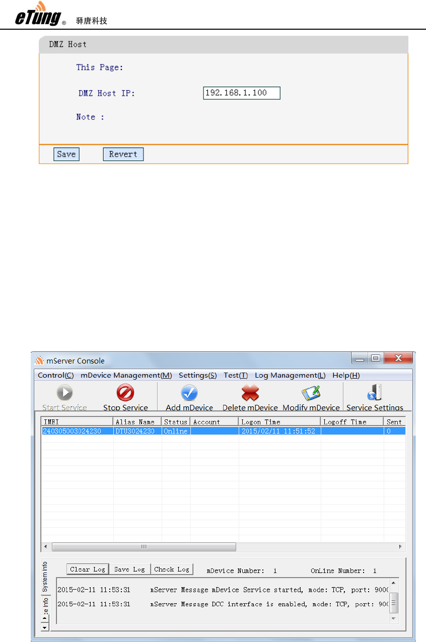
Login the router’s web configuration page, choose “NAT Rule”->”DMZ Host”,
then configure DMZ Host IP as the static IP address of the data center server,
for example, 192.168.1.100 as configured above.
ER-800 User Manual
50
Figure Appendix 3-11: Configure DMZ host
Click “Save”, and then reboot the router. Then data packets received by the
router from the outside network will be forwarded to the data center server.
4. Configure data center address and APN parameters in DTU
Configure data center address and APN parameters as shown in step 3 of
solution one. Set data center IP address to the IP address acquired by the
router after dialing into the network, and data center port as mServer’s
listening port, i.e. 9000 as shown in figure appendix 5-9.
After configuration is complete, reboot DTU, it will dial into APN network, and
then connect to mServer; in mServer’s console we can see that this terminal is
already online.
Figure Appendix 3-12: DTU is online in mServer’s console

ER-800 User Manual
51
After DTU connects to the data center, the application software at the front end
will then be able to communicate with the devices at the far end via virtual
serial port (or other ways).
ER-800 User Manual
52
Appendix 4: Use ER-800 to Access
LAN Remotely via VPN
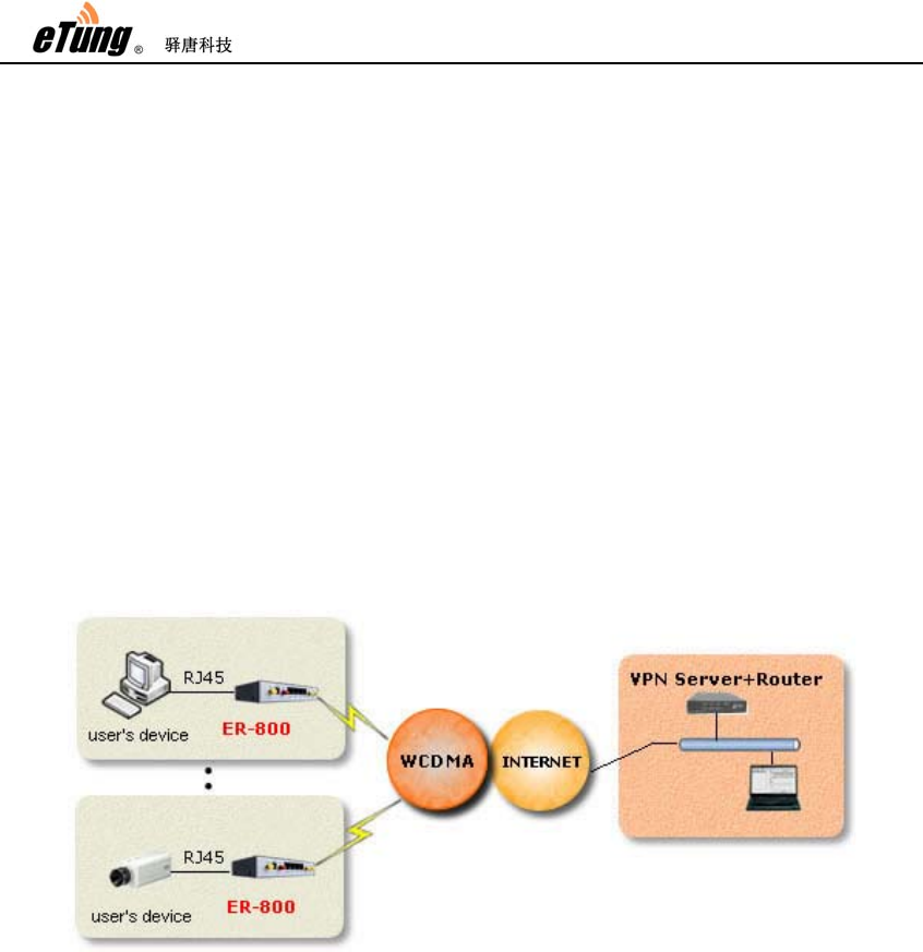
ER-800 can be used to extend and access the corporate virtual LAN remotely with
VPN function, for example, the user can use ER-800 to dial into corporate LAN. But
the router in user's corporate LAN should support VPN in this way. We will illustrate
below how to implement this kind of network connection with VPN.
1. System Architecture
Figure Appendix 4-1: Use ER-800 to access LAN remotely via VPN
2. Preparations
1) One router with VPN function(use PPTP protocol as an example), a LAN is
attached to this router and can access internet;
2) One ER-800(including accessories)
3) One USIM card with internet service(for example China Unicom wo)
4) One PC
3. Steps
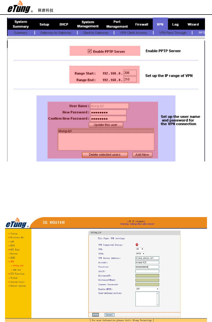
1) Configure to use PPTP when accessing the router
Here we use router RV042 from Linksys as an example. First, this router
supports VPN and PPTP protocol. Login this Linksys router. and click
"VPN"->"PPTP", enable PPTP server and set the IP range for VPN
connection, then create username and password used for VPN connection,
as shown in the figure below:
ER-800 User Manual
53
Figure Appendix 4-2: Configure router's VPN function
Actually different routers have different configuration interface and options,
we can configure it accordingly.
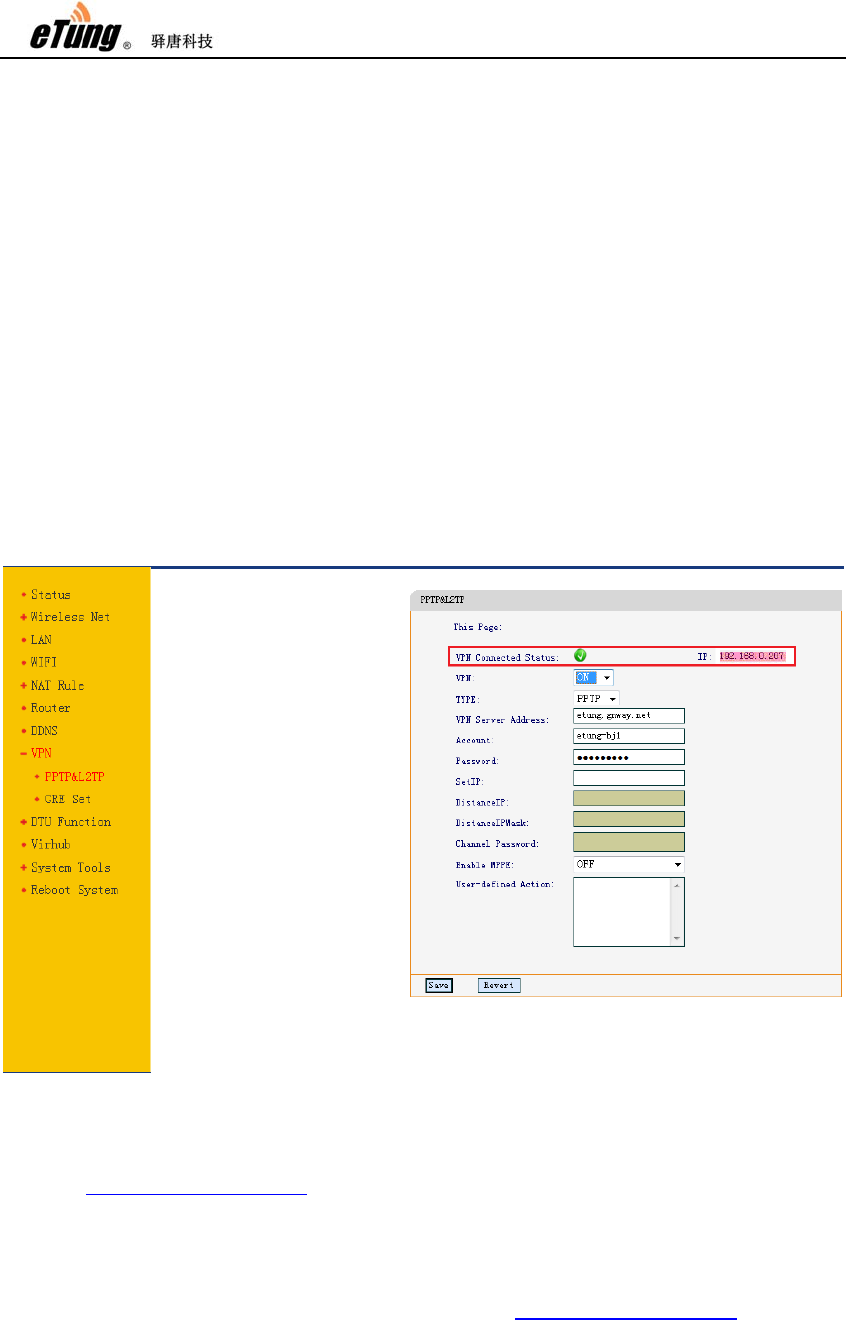
2) Configure ER-800
Login ER-800's configuration interface, click "VPN function" and configure it
as shown in the figure below:
Figure Appendix 4-3: Configure account for VPN function
ER-800 User Manual
54
Type -- PPTP or L2TP
VPN server IP or domain -- the IP address on corporate LAN side, if the
IP address is not static, we recommend to apply a domain free of charge
from Oray or Gnway, then input the domain here, ER-800 supports domain
resolving.
Username -- the username configured in the router at corporate LAN side,
i.e. the username configured in Linksys router before;
Password -- the password configured in the router at corporate LAN side,
i.e. the password configured in Linksys router before;
VPN function -- ON, to enable VPN connection.
After all settings are complete, reboot ER-800.
3) Check dialing status
Login ER-800 to check dialing status, as shown in the figure below:
Figure Appendix 4-4: ER-800 status of accessing LAN
At this time, ER-800 is connected to the corporate LAN, and visiting
http://192.168.0.207 inside the corporate LAN can see ER-800's web login
interface, and at the same time ER-800 can access resources inside the
corporate LAN.
If we connect a video server to ER-800, and configure port forwarding or
DMZ host on ER-800, we can then access http://192.168.0.207 inside the

ER-800 User Manual
55
corporate LAN and then access the video monitoring interface.
Notes:
1) The IP address used by PC or video server that is connected to ER-800 must
not be in the same range as those IP addresses at the corporate LAN side.
For example, if the IP range at the corporate LAN side is 192.168.0.*, then
ER-800 should be in other IP range, for example 192.168.1.*.
2) ER-800 and the PC or video server that connects to it should be in the same
IP range. ER-800's default gateway is 192.168.1.1, and if the IP range of
the PC or video server that connects to ER-800 need to be 192.168.0.*,
then change ER-800's gateway to the same range, for example
192.168.0.1.
ER-800 User Manual
56
Appendix 5: Send/Receive SMS
with the Router and SMS Format
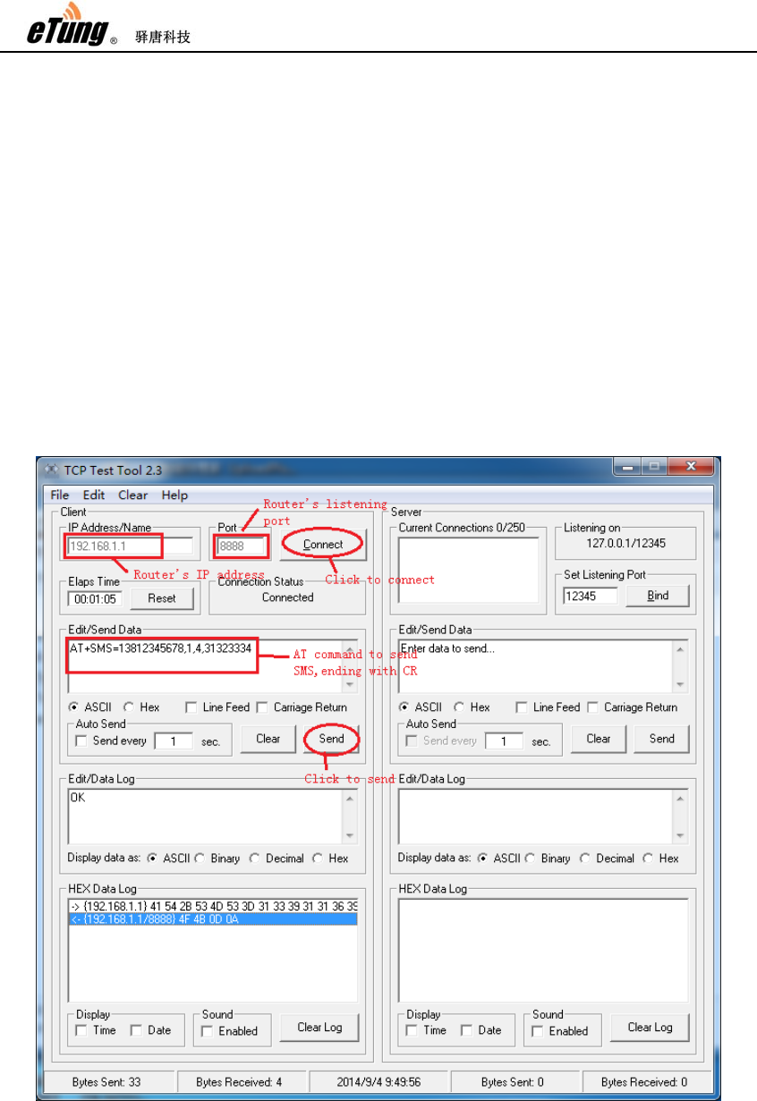
ER-800 supports sending/receiving SMSs via Ethernet interface. The method is
described below:
First, establish a TCP connection with the router’s Ethernet IP (192.168.1.1 by
default) and port: 8888; then use command AT+SMS or AT+SMSA to send SMSs.
For example, use TCP Test Tool to send SMS as shown below:
Figure Appendix 5-1: Send SMS via router’s Ethernet interface
1) In the left part “Client”, input router’s Ethernet IP address “192.168.1.1” in “IP
Address/Name”, and router’s listening port “8888” in “Port”, then click

ER-800 User Manual
57
“Connect” to establish TCP connection with the router; if “Connected” is shown
Connection Status, that means TCP Test Tool has connected to the router’s
listening port.
2) Input AT+SMS or AT+SMSA command in box “Edit/Send Data”, and pay
attention to end with CR, then click “send”; if “OK” is shown in box “Edit/Data
Log”, that means the command has been sent successfully.
NOTE:
1) Currently only ER-800 v1.0.3 or higher version supports sending/receiving
SMSs via Ethernet interface.
2) Currently receiving long SMSs is supported, but sending long SMSs is not
supported, i.e. the length of messages in English cannot exceed 160 characters,
and the length of messages in Chinese cannot exceed 70 words.
3) AT commands must end with CR (0x0d), expressed below as “\r”.
1. Using AT command to send short messages
1) Special AT command for sending short messages with ASCII encoding via
serial port:
AT+SMSA=<target number>,<data length>,<data>\r
DTU will send the following reply:
\r\nOK\r\n
Or:
\r\nERROR\r\n
Target Number: Phone number to receive the short message
Data Length: The actual data length behind
Data: The data to be sent, MUST with ASCII encoding.
Examples:
Send “1234” with ASCII encoding to 13812345678:
AT+SMSA=13812345678,4,1234\r
2) General AT command for sending short messages via serial port:
AT+SMS=<target number>,<encoding format>,<data length>,<data>\r
DTU will send the following reply:
\r\nOK\r\n
Or:
\r\nERROR\r\n
Target Number:Phone number to receive the short message
Encoding Format: 1:ASCII encoding, 2:8bit encoding, 3:Unicode encoding
Data Length: The actual data length behind
Data: The data to be sent, each byte should be formatted to a 2-byte
hexadecimal number, for instance “1234” should be written as“31323334”.
Examples:
Send “1234” with ASCII encoding to 13812345678:
AT+SMS=13812345678,1,4,31323334\r

ER-800 User Manual
58
Use 8bit encoding to send “1234”to 13812345678:
AT+SMS=13812345678,2,4,31323334\r
Use Unicode encoding to send “你好” to 13812345678:
AT+SMS=13812345678,3,4,4F60597D\r
2. The received SMS messages will be output via the serial port in the format
below:
\r\n+SMS:<phone number>,<encoding format>,<data
length>,<data>\r\n
Examples:
“1234” received from 13812345678 in ASCII format:
\r\n+SMS:13812345678,1,4,31323334\r\n
“1234” received from 13812345678 in 8bit encoding:
\r\n+SMS:13812345678,2,4,31323334\r\n
“你好” received from 13812345678 in Unicode encoding:
\r\n+SMS:13812345678,3,4,4F60597D\r\n
If the received SMS has more than one message, the format is as below:
\r\n+SMSL:<identifier>,<total>,<sequence number>,<phone
number>,<encoding format>,<data length>,<data>\r\n
The messages with the same identifier can be assembled into one long
SMS.
For example, a long SMS is received from 10001, with identifier 05000376,
total 4 messages, and below is the fourth message:
\r\n+SMSL:05000376,4,4,10001,3,6,007600793002

ER-800 User Manual
59
Appendix 6: AT Commands on the
Router’s Ethernet Interface
eTung’s wireless routers support AT commands directly coming from Ethernet
interface, to query status, modify parameters, send/receive SMS, etc. The AT
commands that a router supports can be different based on different models and
different firmware versions. Below are the AT commands on the Ethernet interface
that ER-800 V1.0.4 or higher versions support.
Attention: the AT commands MUST be in uppercase, and MUST end with CR(0x0d),
as shown in “\r” below.
For the following commands, please refer the descriptions of AT commands via SMS
in “2.5 Remote Configurations”
1. AT+WN=apn,user,passwd,net_mode\r
2. AT+DC=addr,port,user,mode\r
3. AT+PWD=passwd\r
4. AT+VIRHUB=0/1\r
5. AT+RESTORE\r
6. AT+REBOOT\r
7. AT+STATUS? \r
8. AT+WN? \r
9. AT+DC? \r
10. AT+INFO? \r
11. AT+VIRHUB? \r
12. AT+UPDATE=url\r
13. AT+UPDATEALL=url\r
Following are the AT commands used to send SMS, for details please refer
“Appendix 5: Send/Receive SMS with the Router and SMS Format”.
14. AT+SMS=<target number>,<encoding format>,<data length>,<data>\r
15. AT+SMSA=<target number>,<data length>,<data>\r
Following are the AT commands that can be used only on Ethernet interface, and
currently cannot be used via SMS.
16. AT+UPTIME\r
Get the system’s running time, and the return value is in seconds.
17. AT+DISCCOUNT=YYYYMMDD\r

ER-800 User Manual
60
Get the disconnection times in the specified date, the date format is
YYYYMMDD, and the reply is the times of disconnection during that day.

ER-800 User Manual
61
FCC Warning
This device complies with Part 15 of the FCC Rules. Operation is subject to the following two
conditions:
(1) This device may not cause harmful interference, and (2) this device must accept any interference
received, including interference that may cause undesired operation.
NOTE 1: This equipment has been tested and found to comply with the limits for a Class B digital
device, pursuant to part 15 of the FCC Rules. These limits are designed to provide reasonable
protection against harmful interference in a residential installation. This equipment generates, uses and
can radiate radio frequency energy and, if not installed and used in accordance with the instructions,
may cause harmful interference to radio communications. However, there is no guarantee that
interference will not occur in a particular installation. If this equipment does cause harmful
interference to radio or television reception, which can be determined by turning the equipment off
and on, the user is encouraged to try to correct the interference by one or more of the following
measures:
- Reorient or relocate the receiving antenna.
- Increase the separation between the equipment and receiver.
-Connect the equipment into an outlet on a circuit different from that to which the receiver is
connected.
-Consult the dealer or an experienced radio/TV technician for help.
NOTE 2: Any changes or modifications to this unit not expressly approved by the party responsible
for compliance could void the user's authority to operate the equipment.
The transmitter must not be co-located or operated in conjunction with any other antenna or
transmitter. This equipment complies with the FCC RF radiation exposure limits set forth for an
uncontrolled environment. This equipment should be installed and operated with a minimum distance
of 20cm between the radiator and any part of your body.