Eurotech Appliances Com 1460 Users Manual CPU 1232
COM-1460 to the manual 6fde4802-4d63-4a1d-b8ec-44b71854167f
2015-02-02
: Eurotech-Appliances Eurotech-Appliances-Com-1460-Users-Manual-427078 eurotech-appliances-com-1460-users-manual-427078 eurotech-appliances pdf
Open the PDF directly: View PDF ![]() .
.
Page Count: 38
Embedded
EmbeddedEmbedded
EmbeddedDNA
DNADNA
DNA
®
PC/104-Plus CPU Module
User’s Manual
COPYRIGHT 1994-2002 Eurotech S.p.A. All Rights Reserved.
Rev. 1.0 Sep. 2002
COM-146
0

2 PC/104-Plus – COM-1460 Module
ABOUT THIS MANUAL
This manual is meant for engineers and programmers who wish to develop systems based on the Eurotech
COM-1460 PC/104-Plus module. It contains the module’s technical specifications, and describes the connections
and firmware/software.
It also describes how to install, configure and troubleshoot the COM-1460 module.
Via J. Linussio 1
33020 AMARO (UD)
ITALY
Phone: +39 0433 485 411
Fax: +39 0433 485 499
web: http://www.eurotech.it
e-mail: mailto:sales@eurotech.it
NOTICE
Although all the information contained herein has been carefully verified, Eurotech S.p.A. assumes no
responsibility for errors that might appear in this document, or for damage to property or persons
resulting from an improper use of this manual and of the related software. Eurotech S.p.A. reserves the
right to change the contents and form of this document, as well as the features and specifications of its
products at any time, without notice.
Trademarks and registered trademarks appearing in this document are the property of their respective owners
PC/104-Plus – COM-1460 Module 3
Conventions
The following table lists conventions that are used throughout this guide.
Icon Notice Type Description
Information note Important features or
instructions
Warning
Information to alert you to
potential damage to a program,
system or device or potential
personal injury
(This page is intentionally left blank.)

Contents
Conventions.................................................................................................................................................... 3
Contents............................................................................................................................................................ 5
Chapter 1 Product Overview....................................................................................................................... 7
COM-1460 module’s functional blocks........................................................................................................... 8
Product Definition ........................................................................................................................................... 8
COM-1460 PC/104-Plus Module characteristics .....................................................................................8
Chapter 2 Jumper Description.................................................................................................................... 9
Jumper Layout and Configuration ................................................................................................................ 10
Chapter 3 Connectors Description........................................................................................................... 13
Connectors Layout ....................................................................................................................................... 14
J1, J2 for the ISA Bus and J3 for the PCI Bus ............................................................................................. 15
The ISA BUS.......................................................................................................................................... 15
The PCI BUS ......................................................................................................................................... 15
How to connect the COM-1460 to other PC/104 & PC/104-Plus devices: the stack assembly ............ 15
J7, J8, J9 for Firewire ................................................................................................................................... 17
J10 for Main Power....................................................................................................................................... 17
Chapter 4 Troubleshooting ....................................................................................................................... 19
Common Problems and Solutions................................................................................................................ 20
Troubleshooting a PC/104-Plus System ...................................................................................................... 20
Technical/Sales Assistance.......................................................................................................................... 20

6 PC/104-Plus – COM-1460 Module
Returning For Service................................................................................................................................... 21
Appendix......................................................................................................................................................... 25
A.1 Electrical and Environmental Specifications...................................................................................... 26
Operating Characteristics ...................................................................................................................... 26
Absolute Maximum Ratings ................................................................................................................... 26
MTBF ..................................................................................................................................................... 27
A.2 Mechanical Dimensions..................................................................................................................... 28
Module Dimensions ............................................................................................................................... 28
A.2 Safety Summary ................................................................................................................................ 29
Ground the Instrument........................................................................................................................... 29
Do Not Operate in an Explosive Atmosphere........................................................................................ 29
Keep Away From Live Circuits............................................................................................................... 29
Use Caution When Exposing or Handling the CRT............................................................................... 29
Do Not Substitute Parts or Modify Equipment ....................................................................................... 29
Observe Dangerous Procedure Warnings............................................................................................. 29
Flammability........................................................................................................................................... 29
EMI Caution ........................................................................................................................................... 30
CE Notice............................................................................................................................................... 30
Disclaimer of Warranty .......................................................................................................................... 30
Notice..................................................................................................................................................... 30
Reliability................................................................................................................................................ 30
Life Support Policy ................................................................................................................................. 30
Glossary.......................................................................................................................................................... 31
Acronyms and Abbreviations ....................................................................................................................... 37

8 PC/104-Plus – COM-1460 Module
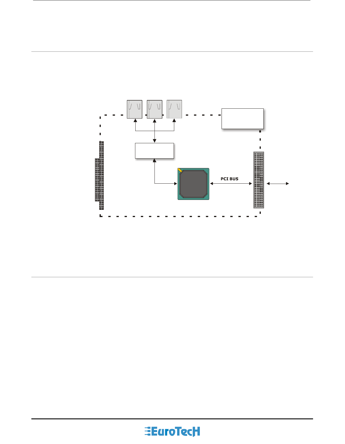
COM-1460 module’s functional blocks
The figure below shows the functional blocks diagram of the module.
TSB41LV03A
PCI BUS
ISA BUS
(For pass
through only)
signal
CTR-1460
Module
Firewire3 Firewire2 Firewire1
Physical
Interface
Link
Interface
PCI4450
Figure 1. Functional blocks of the COM-1460 module
Product Definition
COM-1460 PC/104-Plus Module characteristics
PC/104-Plus Form Factor: 90 X 96 mm (3.6”X3.8”), height 15 mm (0.6”)
PCI/ISA compliant with the PC/104-Plus standard
3 Firewire connectors
1 External Power Connector
Low power consumption.
High reliability.

Chapter 2 Jumper Description
This chapter shows the jumpers layout and explains how to set up the jumpers.
10 PC/104-Plus – COM-1460 Module
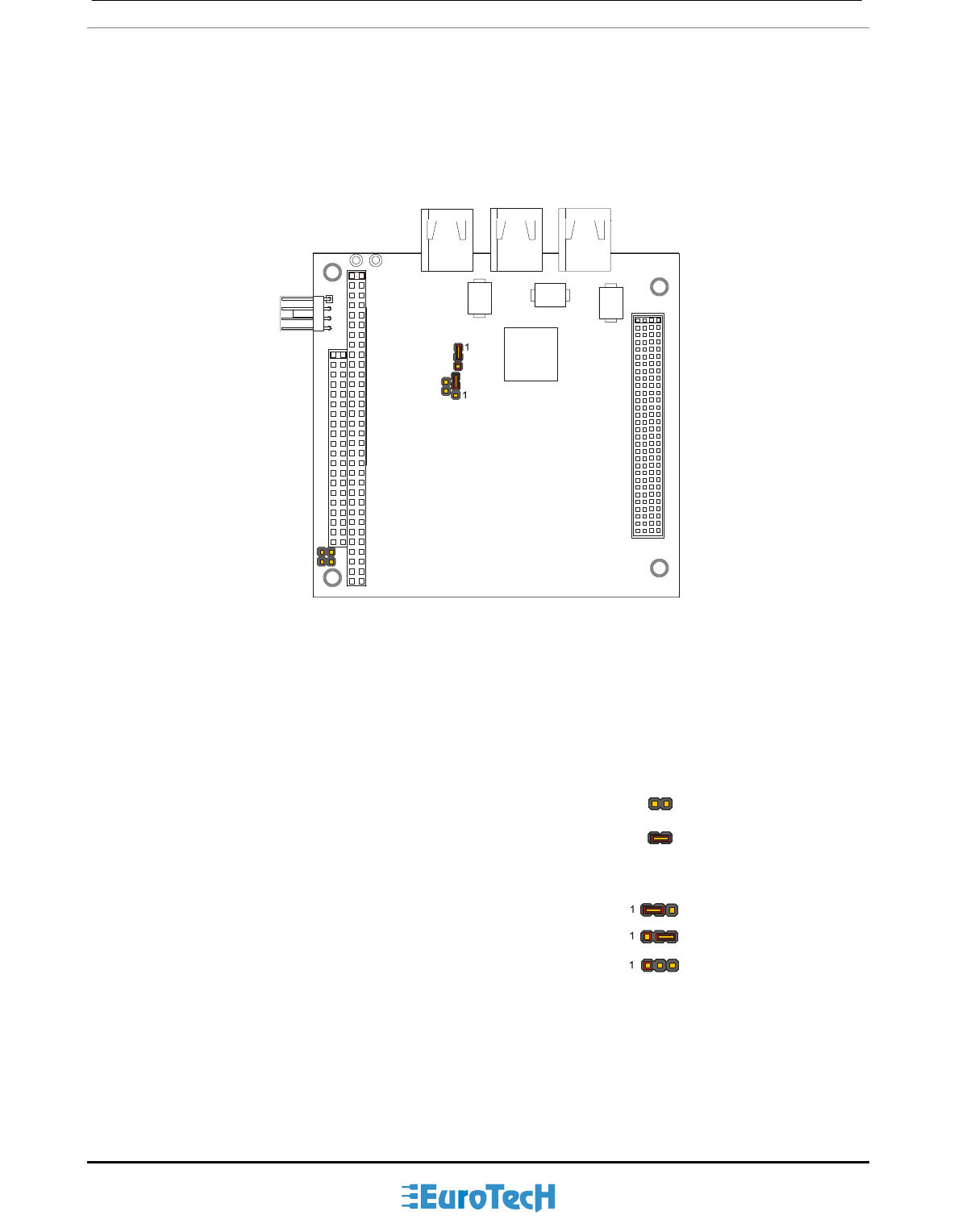
Jumper Layout and Configuration
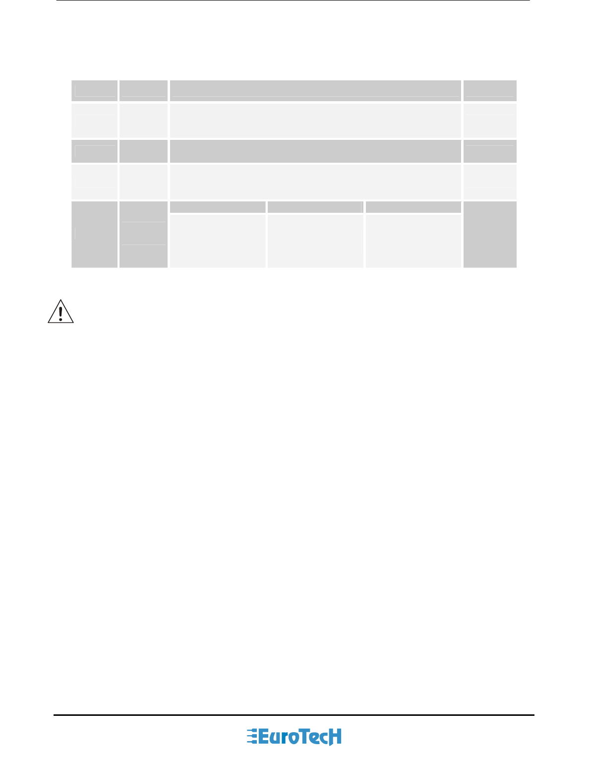
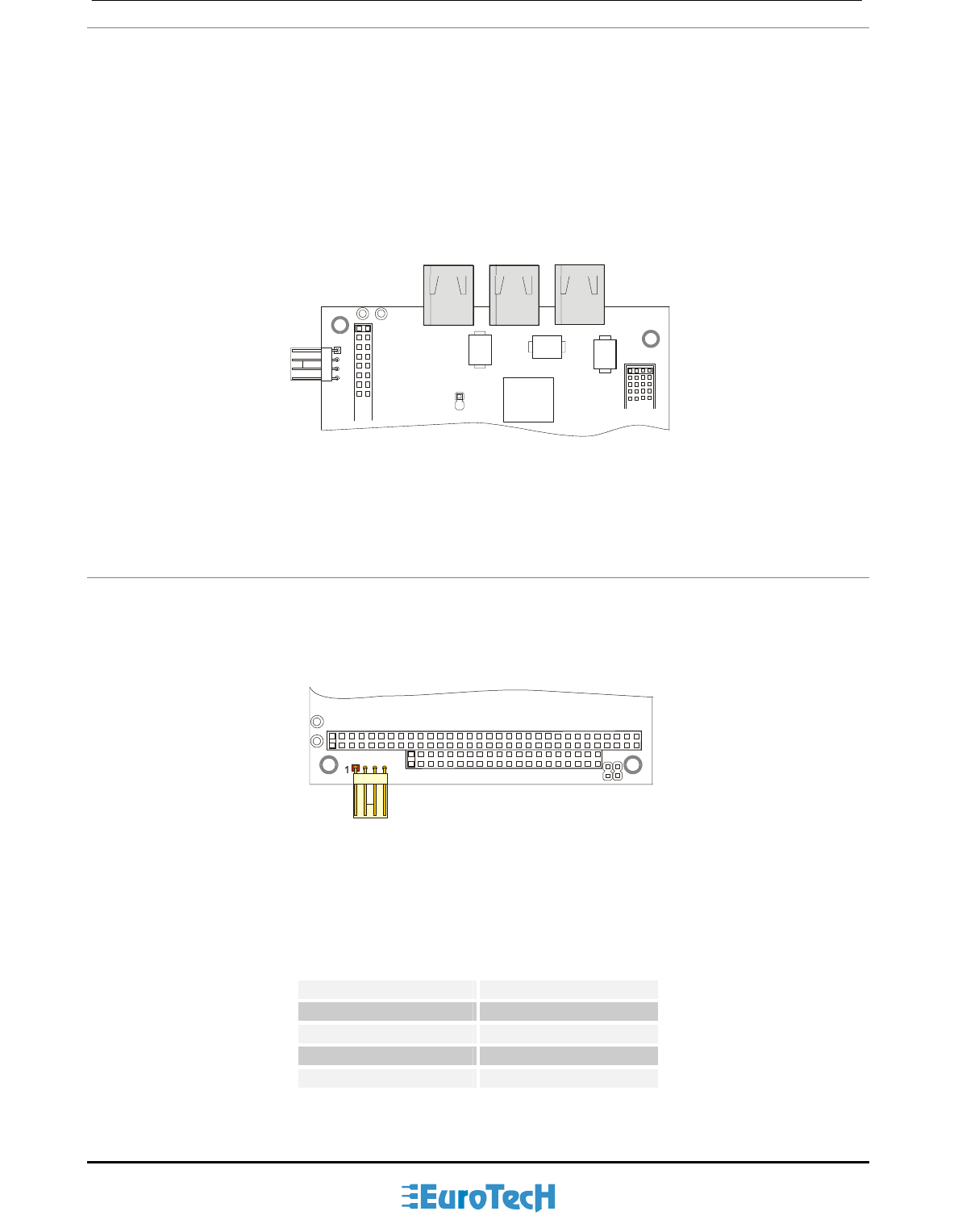
The figure below shows the jumper layout of the COM-1460 module.
In the figure below, the jumpers are indicated as JP followed by the jumper's number, while pin 1 of every
three pin jumper is indicated by a red square pad.
JP3
JP2
JP5
JP4
JP1
Figure 2. Jumpers on the COM-1460 module
The following jumpers are located on the module:
Three 2-pin jumpers which can be set as follows:
pin 1 and pin 2 not connected (which will be indicated as ‘Open’)
pin 1 connected to pin 2 (which will be indicated as ‘Closed’)
Two 3-pin jumpers which can be set as follows:
pin 1 connected to pin 2 (which will be indicated as ‘1-2’)
pin 2 connected to pin 3 (which will be indicated as ‘2-3’)
no pins connected (Open). This setting is not allowed
= 2-3
= 1-2
= Open
= Closed
= Open
PC/104-Plus – COM-1460 Module 11
The following table provides a quick cross-reference for them.
Table 1. Jumpers Function
JP Type Function Default
JP1 3 pin
jumper
Power supply for physical interface
1-2: Reserved
2-3: Power supply comes from J10
2-3
JP2 2pin
jumper
GND to GND_A
JP2 must be left open Open
JP3 3 pin
jumper
Setting for Bus Manager Contender (BMC) state at reset
1-2: Not Bus Manager Contender
2-3: Bus Manager Contender
1-2
JP4 JP5 Slot #*
JP4-JP5 2 pin
jumper JP4 must be left
open
JP5 must be left
open
Put COM-1460 on
the top of the stack
Open
-
Open
* Two jumpers (JP4 and JP5 in this case) are located on every PC/104-Plus peripheral module,
and are used to set the module’s Slot number. The module closest to the CPU Module starts
with Slot 0. Because in the stack no more than four modules are supported (in addiction to the
CPU module) the allowed values are only: 0, 1, 2 and 3. COM-1460 is normally put on the top of
the stack.
(This page is intentionally left blank.)

Chapter 3 Connectors Description
This chapter provides a brief description of the COM-1460 module’s connectors, with their positions and
functions.
14 PC/104-Plus – COM-1460 Module
Connectors Layout
The following figure shows the connectors with their layout and describes their function.
Firewire
Main Powe
r
Firewire Firewire
J9
J10
J8 J7
J3
PCI BUS
J1 J2
Figure 3. Connectors layout
Note: in the above figure, a red square pad indicates pin 1 of each connector.
The table below lists the name of the connectors with their function and the reference page.
Table 2. Connector Functions
Connector Function Pag.
J1-J2 ISA BUS 15
J3 PCI BUS 15
J7 Firewire 1 17
J8 Firewire 2 17
J9 Firewire 3 17
J10 Main Power 17
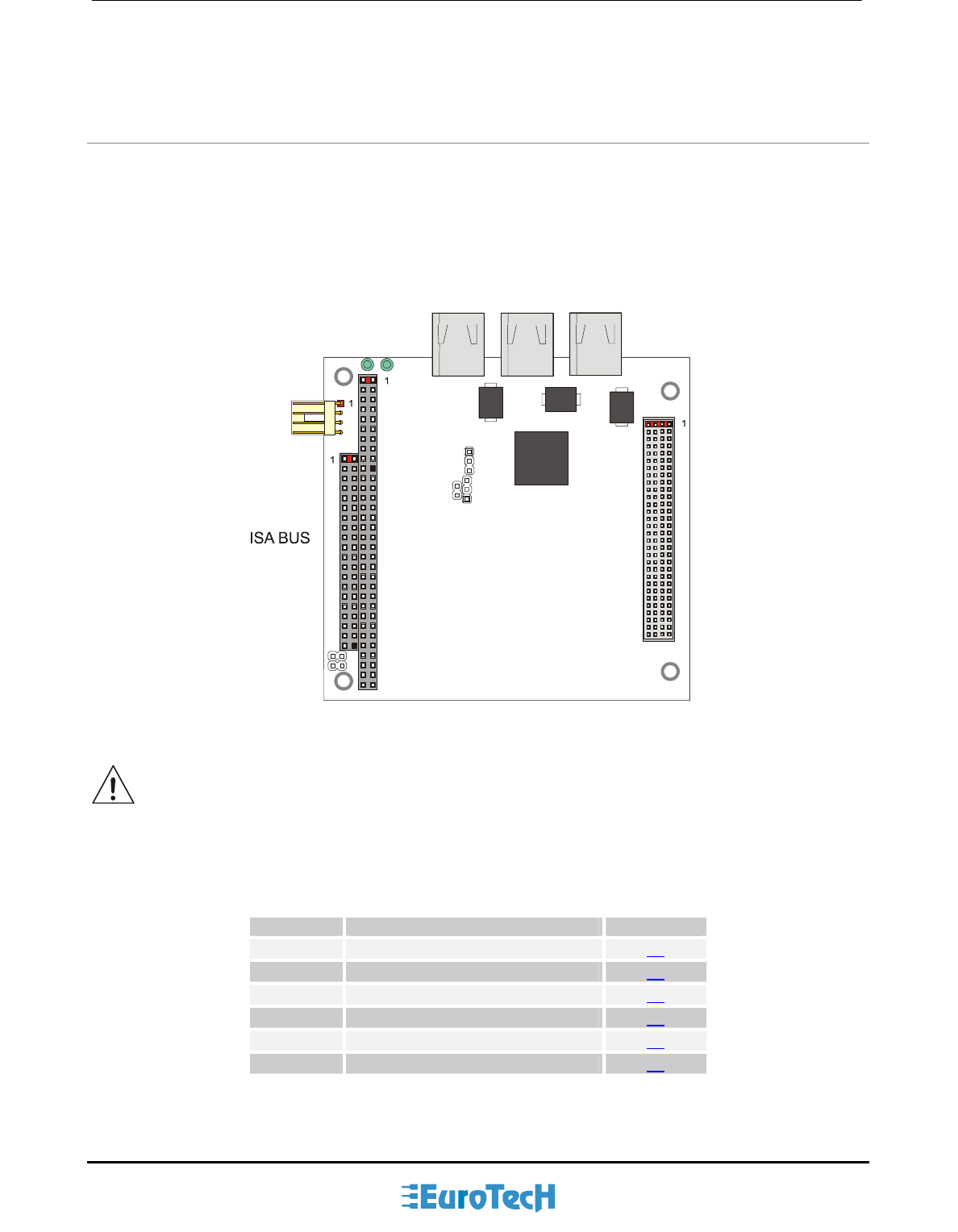
PC/104-Plus – COM-1460 Module 15
J1, J2 for the ISA Bus and J3 for the PCI Bus
The ISA BUS
Connectors J1 and J2 carry the signals for the ISA Bus.
The ISA BUS signals are not used from the COM-1460. The only function of the ISA connector is the
“passing-through” of the signals, and giving compatibility to the stack assembly.
Below is shown a picture of the ISA BUS
J1
J2
Figure 4. ISA BUS layout
According to PC/104 specifications: “Key” locations - consisting of plugged holes in the upper side and
omitted pins in the lower side - have been designated on each bus connector (on J1 and J2), to help assure
proper connector mating.”
The PCI BUS
Connector J3 carries signals of the PCI Bus. The PCI Bus mechanical interface is a stackable 30x4 header.
This interface carries all of the required PCI signals per PCI Local Bus Specification Version. 2.1.
In the following page is shown a picture of the PCI BUS
J3
PCI BUS
Figure 5. PCI BUS layout
For further information about the ISA bus and the PCI bus please refer to Eurotech web site
(http://www.eurotech.it/) in the section Industry Standards.
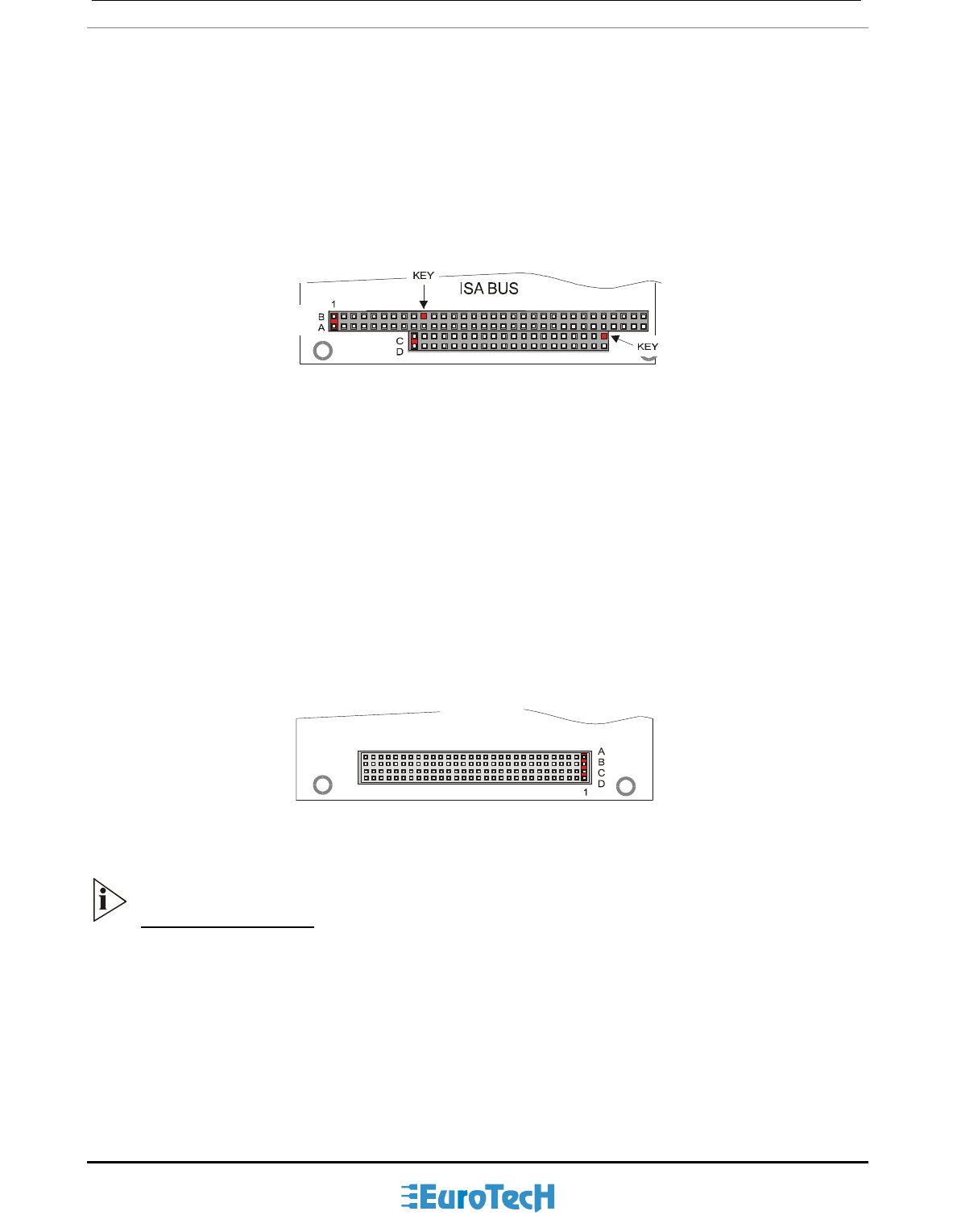
How to connect the COM-1460 to other PC/104 & PC/104-Plus devices: the stack
assembly
The ISA Bus connectors of the module are designed to allow the connection onto a stack of other PC/104
and/or PC/104-Plus devices.
We recommend you follow the procedure described below to ensure that stacking of the modules does not
damage connectors or electronic parts.
16 PC/104-Plus – COM-1460 Module
1. Turn off power to the PC/104-Plus system or stack.
2. Select and install standoffs to properly position the module on the PC/104-Plus stack.
3. Touch a grounded metal part of the rack to discharge any buildup of static electricity.
4. Remove the module from its anti-static bag.
5. Check that keying pins in the bus connector are properly positioned.
6. Check the stacking order; make sure an XT bus card will not be placed between two AT bus cards or it
will interrupt the bus’s signals.
7. Hold the module by its edges and orient it so that the bus connector pins line up with the matching
connector on the stack.
8. Press the module evenly onto the PC/104-Plus stack.
9. Verify that all the connections are properly made
10. Switch on the power
If standard PC/104 modules are used in the stack, they must be the top module(s) because they will
normally not include the PCI bus.
The following picture shows an example of a module stack with 2 PC/104-Plus modules, 1 PC/104 16-BIT
module, and 1 PC/104 8-BIT module.
The maximum number of PC/104-Plus modules is 4 plus the (PC/104-Plus compliant) CPU board.
If standard PC/104 modules are used in the stack, they must be the top module(s) because they will
normally not include the PCI bus.
If the CPU is PC/104 compliant you can only stack PC/104 modules and use only the ISA buses
on the Backplane. If the CPU is PC/104-Plus compliant you can stack both PC/104 and PC/104-
Plus modules and use both PCI and ISA buses on the Backplane.
0.6 in. (15mm) Spacers (4 plcs.)
Stackthrough
8-bit module 0.435 in. (11 mm)
0.6 in. (15 mm)
Stackthrough
16-bit module
Stackthrough
PC/104Plus module
Non-Stackthrough
PC/104Plus module
0.6 in. (15mm) Spacers (4 plcs.)
0.6 in. (15mm) Spacers (4 plcs.) 0.100 in. (2.54 mm) 0.062 in. (1.57 mm)
Figure 6. The Module Stack
Do not force the module onto the stack! Wiggling the module or applying too much pressure
may damage it. If the module does not readily press into place, remove it, check for bent pins
or out-of-place keying pins, and try again.
PC/104-Plus – COM-1460 Module 17
J7, J8, J9 for Firewire
Each of the Firewire ports - compliant with the IEEE 1394 OHCI standard - is a high speed bus that supports
data transfer rates up to 400Mbps (100/200/400 Mbps selectable) and delivers more than 30 times the
bandwidth of the popular USB peripheral standard. Each of these ports can be used to connect up to 63
external devices, support “hot plug-and-play” and provide power supply to peripherals through an internal
DC/DC converter (that is specifically used to isolate power between the physical layer and the host
computer). The Firewire bus is Power Class 1.
Firewire3 Firewire2 Firewire1
J9 J8 J7
Figure 7. Firewire ports
J10 for Main Power
J10 is a 4-pin with 2.54-mm step connector that implements the Main Power supply function.
You must provide power to the COM-1460 module before using the Firewire ports.
Main Powe
r
J10
Figure 8. Main Power connector
The connector pinout is given below.
Table 3. J10 connector pinout
Pin Signal
1 +8 - +40V
2 GND
3 GND
4 -
(This page is intentionally left blank.)

Chapter 4 Troubleshooting
Many problems that you may encounter with your COM-1460 module are due to common errors such as bad
(cable) connections or incorrect settings in the Setup Program.
This chapter will help you attain proper system operation.
It contains:
Common problems and solutions
Troubleshooting a PC/104-Plus system
How to obtain technical support
How to return a product

20 PC/104-Plus – COM-1460 Module
Common Problems and Solutions
The following table lists some of the common problems that you may encounter using your COM-1460
module, and suggests possible solutions. If you have problems with your COM-1460 module, please review
this table before contacting technical support.
Table 4. Common problems and solutions
COM-1460 Module doesn’t work
No power or wrong polarity Check for correct power on PC/104 and PC/104-Plus bus connectors
Defective or mis-connected device
on bus
Check for misaligned bus connectors, remove other cards from stack
Cable connected backwards Verify all cables are connected properly
Troubleshooting a PC/104-Plus System
If you have reviewed the preceding table and still cannot isolate the problem with your COM-1460 module,
please try the following troubleshooting steps. Even if the resulting information does not help you find the
problem, it will be very helpful when contacting technical support.
Simplify the system. Remove items one at a time and see if one particular item seems to cause the
problem.
Swap components. Try replacing items in the system one-at-a-time with similar items.
Technical/Sales Assistance
If you have a technical question, please call Eurotech Customer Support Service at one of the numbers
below, or e-mail our technical support team at:
mailto:techsupp@eurotech.it
Phone: +39-0433-485 411
Fax: +39-0433-485 499
If you have a sales question, please contact your local Eurotech Sales Representative or the Regional Sales
Office for your area.
PC/104-Plus – COM-1460 Module 21
Visit the Eurotech web site for additional and current information:
http://www.eurotech.it/
and then select the DownLoad Area
Old and new versions of manuals, application notes, patches, drivers and BIOS files can be found at:
ftp://ftp.eurotech.it/
Returning For Service
Before returning any of Eurotech's products, you must call Eurotech Technical Support at +39-0433-485411
or fill in and send (by Fax: +39 0433 485499 or mailto:techsupp@eurotech.it) the “Repair Order Module” to
obtain a Returned Material Authorization (RMA) number. The Module will be returned to you with the RMA
number for enclosure with the returned products.
Note. You must have the RMA number in order to return any product for any reason!
The following information is needed to expedite the shipment of a replacement to you:
Your company name and address for invoice
Shipping address and phone number
Product I.D. number
The name of a technically qualified individual at your company familiar with the mode of failure on the
board
A detailed description of the problem and of the current configuration including OS and software loaded.
If the unit is out of warranty, service is available at a pre-established service charge. Contact Eurotech for
pricing and please supply a purchase order number for invoicing the repair.
Pack the board in an anti-static material and ship it in a sturdy cardboard box with enough packing material
to adequately cushion it.
Warning! Any product returned to Eurotech improperly packed will immediately void the warranty for
that particular unit!
(This page is intentionally left blank.)
Repair Order Module
For order repair or replacement of a defective Eurotech product, please complete this document.
RMA: Don’t write anything into the space to the left. Your Return Material Authorization
number will be assigned by Eurotech Technical Support
Company Name:
Division:
Contact Name:
Telephone: Email:
Fax:
Product name or
model:
Serial Number:
O.S. Used:
Problem description
In accordance with the Limited warranty on this product, Eurotech or its representative will, at its option,
determine whether the defective product will be repaired or replaced. If the warranty has expired, or if the
product does not qualify for warranty service, you will be billed a service fee.
Notes:
(This page is intentionally left blank.)

Appendix
26 PC/104-Plus – COM-1460 Module
A.1 Electrical and Environmental Specifications
The following section provides tables and illustrations showing the electrical, mechanical and environmental
specifications for the COM-1460 module.
In the following tables you will find:
Operating Characteristics
Electrical operating characteristics
Operating temperature range
Absolute maximum ratings
MTBF
Operating Characteristics
Electrical Operating Characteristics
The board needs the following voltages to operate properly:
PCI/104-Plus +5V
External Power +8V - +40V (usually +12V)
Current Draw: 450mA @+5V (max)
Note. This module is not warranted against damage caused by overheating due to improper or
insufficient cooling or airflow.
Operating Temperature Range
For proper operation of the module, the ambient air temperature must remain inside this range:
0°C to +60°C (+32°F to +140°F).
Absolute Maximum Ratings
Table 5. Absolute Maximum Ratings
Supply Voltage: Vcc: 0.00 to 7.00V
Storage Temperature Range: -40°C to +85°C (-40°F to +185°F)
Non-Condensing Relative Humidity: <95% at 40°C (+104°F)
PC/104-Plus – COM-1460 Module 27
The module with extended Operating Temperature Range, –40°C to +85°C (-40°F to 185°F), version is also
available.
Warning! Stressing the device beyond the “Absolute Maximum Ratings” may cause permanent
damage. These are stress ratings only. Operation beyond the “Operating Conditions” is not
recommended. Extended exposure beyond the “Operating Conditions” may affect device
reliability.
MTBF
Hours: 795110.3 Standard: MIL-HDBH-217 Condition: GB25
28 PC/104-Plus – COM-1460 Module
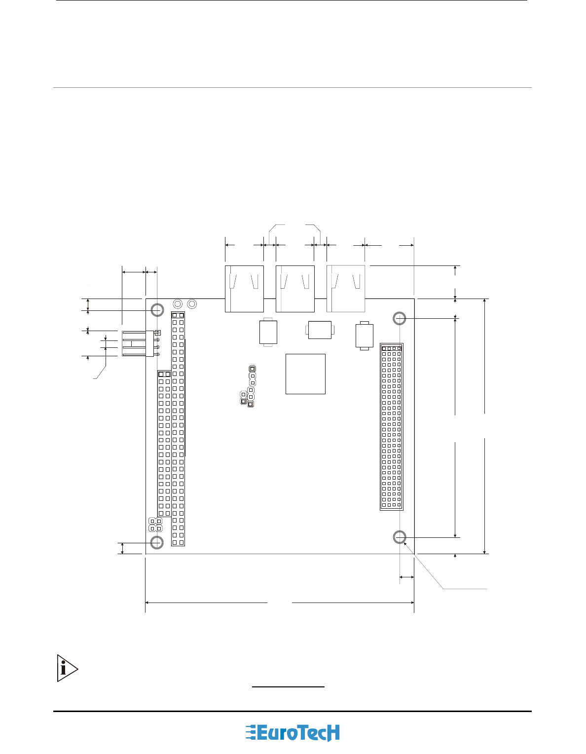
A.2 Mechanical Dimensions
Module Dimensions
The COM-1460 module’s mechanical dimensions are shown in the following picture:
Dimensions: 90 X 96 mm (3.6”X3.8”), height 15 mm (0.6”)
96.0
90.2
5.1
5.1
4.6
5.1
18.5
8.0
10.2
6.1
2.54
8.9 9.0
7.6
Ø 6.4 PAD
Ø 3.2 HOLE
73.7
5.1
12.1 12.1
12.1
Dimensions are in millimeters
Figure 9. COM-1460 Board dimensions
Note: For further information about the mechanical dimensions of ISA and PCI buses please
refer to the PC/104 consortium site (www.pc104.org)

PC/104-Plus – COM-1460 Module 29
A.2 Safety Summary
The following general safety precautions must be observed during all phases of operation, service, and
repair of this equipment. Failure to comply with these precautions or with specific warnings elsewhere in this
manual violates safety standards of design, manufacture, and intended use of the equipment. Eurotech SpA
assumes no liability for the customer’s failure to comply with these requirements.
The safety precautions listed below represent warnings of certain dangers of which Eurotech is aware. You,
as the user of the product, should follow these warnings and all other safety precautions necessary for the
safe operation of the equipment in your operating environment.
Ground the Instrument
To minimize shock hazard, the equipment chassis and enclosure must be connected to an electrical ground.
The equipment is supplied with a three-conductor ac power cable; the power cable must be plugged into an
approved three-contact electrical outlet, with the grounding wire (green) firmly connected to an electrical
ground (safety ground) at the power outlet. The power jack and mating plug of the power cable meet
International Electro technical Commission QEC) safety standards.
Do Not Operate in an Explosive Atmosphere
Do not operate the equipment in the presence of flammable gases or fumes. Operation of any electrical
equipment in such an environment constitutes a definite safety hazard.
Keep Away From Live Circuits
Operating personnel must not remove equipment covers. Only Factory Authorized Service Personnel or
other qualified maintenance personnel may remove equipment covers for internal subassembly or
component replacement or any internal adjustment. Do not replace components with power cable
connected. Under certain conditions, dangerous voltages may exist even with the power cable removed. To
avoid injuries, always disconnect power and discharge circuits before touching them.
Use Caution When Exposing or Handling the CRT
Breakage of the Cathode-Ray Tube (CRT) causes a high-velocity scattering of glass fragments (implosion).
To prevent CRT implosion, avoid rough handling or jarring of the equipment. Only qualified maintenance
personnel using approved safety mask and gloves should handle the CRT.
Do Not Substitute Parts or Modify Equipment
Because of the danger of introducing additional hazards, do not install substitute parts or perform any
unauthorized modification of the equipment. Contact Eurotech technical staff or your local representative for
service and repair to ensure that safety features are maintained.
Observe Dangerous Procedure Warnings
Warnings, such as the example below, precede potentially dangerous procedures throughout this manual.
Instructions contained in the warnings must be followed. You should also employ all other safety
precautions, which you deem necessary for the operation of the equipment in your operating environment.
Flammability
All Eurotech PWBs (printed wiring boards) are manufactured by UL-recognized manufacturers, with a
flammability rating of UL-V0.

30 PC/104-Plus – COM-1460 Module
EMI Caution
This equipment generates, uses and can radiate electromagnetic energy. It may cause or be susceptible to
electromagnetic interference (EMI) if not installed and used in a cabinet with adequate EMI protection.
CE Notice
This product complies with the EMC Directive (89/336/EEC). Compliance with this directive implies
conformity to the following European Norms:
EN55022 (CISPR 22) Radio Frequency Interference
EN50082-1 (IEC801-2, IEC801-3, IEC801-4) Electromagnetic Immunity
The product also fulfills EN60950 (product safety), which is essentially the requirement for the Low Voltage
Directive (73/23/EEC).
This product was tested in a representative system to show compliance with the above-mentioned
requirements. A proper installation in a CE-marked system will maintain the required EMC/safety
performance.
Disclaimer of Warranty
THIS MANUAL IS PROVIDED ’AS IS’ WITHOUT WARRANTY OF ANY KIND, EITHER EXPRESS OR
IMPLIED, INCLUDING, BUT NOT LIMITED TO, THE IMPLIED WARRANTIES OF MERCHANTABILITY
AND FITNESS FOR A PARTICULAR PURPOSE. The laws of some states and countries do not allow the
disclaimer of express or implied warranties in certain transactions; therefore, this statement may not apply to
you. As such, the above warranty disclaimer shall only apply to the extent permitted by law.
Notice
While reasonable efforts have been made to assure the accuracy of this document, Eurotech S.p.A.
assumes no liability resulting from any omissions in this document, or from the use of the information
contained therein. It is not warranted that the contents of this publication or any accompanying source code
examples, whether individually or as one or more groups, will meet your requirements or that the publication
or the accompanying source code examples are error-free. This publication could include technical
inaccuracies or typographical errors.
Eurotech reserves the right to revise this document and to change its contents at any time without obligation
to notify any person of such revision or changes.
Any reference to a licensed program in this publication is not intended to state or imply that you can use only
that licensed program. You can use any functionally equivalent program instead.
No part of this material may be reproduced or copied in any tangible medium, or stored in a retrieval system,
or transmitted in any form or by any means, radio, electronic, mechanical, photocopying, recording or
facsimile, or otherwise, without the prior written permission of Eurotech S.p.A.
Reliability
Eurotech has taken extra care of product design in order to ensure reliability. The two major ways in which
reliability is achieved are:
The product is designed in top-down method, utilizing the latest in hardware and software
techniques, so unwanted side effects and improper interactions between parts of the system are
eliminated.
Eurotech tests each board by exercising its functions, burns it in under power, and retests it to
ensure that the infant mortality phase is passed before the product is shipped.
Life Support Policy
Eurotech products are not authorized for use as critical components in life support devices or systems
without the express written approval of the president of Eurotech S.p.A.

Glossary
A
ATA
Advanced Technology Attachment, is a disk drive implementation integrating the controller on the disk drive.
There are several versions of ATA:
ATA: Known also as IDE, supports one or two hard drives, a 16-bit interface and PIO modes 0, 1
and 2.
ATA-2: Supports faster PIO modes (3 and 4) and multiword DMA modes (1 and 2). Also supports
Logical Block Addressing (LBA) and block transfers. ATA-2 is marketed as Fast ATA and Enhanced
IDE (EIDE).
ATA-3: Minor revision to ATA-2.
Ultra-ATA: Also called Ultra-DMA, ATA-33, and DMA-33, supports multiword DMA mode 3 running
at 33 MBps.
ATA/66: A new version of ATA, that will double ATA's throughput to 66 MBps
ATAPI
Short for AT Attachment Packet Interface, an extension to EIDE that enables the interface to support CD-
ROM players
B
BIOS
Basic I/O system. A set of routines that works closely with the hardware to support the transfer of information
between elements of the system, such as memory, disks, and the monitor. Although critical to performance,
the BIOS is usually invisible to the end user; however, programmers can access it.

32 PC/104-Plus – COM-1460 Module
C
CPU
CPU (Central Processing Unit) is the heart (computational and control unit) of a computer.
This device interprets and executes instructions.
CVBS
CVBS Composite Video Broadcasting Signal
D
DMA
The Direct Memory Access is a technique for transferring data from the memory to a device. Data doesn’t
pass through the CPU.
DEVICE
It is any circuit performing a specific function.
E
ECP
Extended Capabilities Port. An asynchronous, 8-bit–wide parallel channel defined by IEEE 1284-1944 that
provides PC-to-peripheral and peripheral-to-PC data transfers.
EEPROM
EEPROM (also known as E2PROM) stands for Electronic Erasable Programmable ROM.
This type of memory can be re-programmed by electronic signals.
EPROM
EPROM stands for Erasable Programmable ROM.
This type of memory can only be erased by ultra-violet (UV) light.
ETHERNET
It is a type of Local Area Network (LAN) architecture. Ethernet supports data transfer rates of 10Mbps.
A newer version of Ethernet, called Fast Ethernet (or 100Base-T), supports data transfer rates of 100 Mbps.
And the newest version, Gigabit Ethernet supports data rates of 1 Gbit (1000 megabits) per second.
F
FDC
Floppy Disk Controller. A special-purpose chip and associated circuitry that directs and controls reading from
and writing to a computer’s disk drive.
FIFO
First in/first out. A method for processing a queue in which items are removed in the same order in which
they were added.
Flash ROM
Flash ROM (like EEPROM) can be re-programmed by electronic signals. Usually a Flash ROM has a
capacity of 1MB.Into this memory usually resides BIOS and other useful programs or instructions.

PC/104-Plus – COM-1460 Module 33
Firewire
Firewire is a high speed bus that supports data transfer rates up to 400Mbps (100/200/400 Mbps selectable)
and delivers more than 30 times the bandwidth of the popular USB peripheral standard.
H
HDC
Hard Disk Controller is a special-purpose chip and circuitry that directs and controls reading from and writing
to a computer’s disk drive.
I
IDE
Integrated Device Electronics is a disk drive interface where the controller electronics reside on the drive
itself. This allows elimination of the need for a separate adapter card.
IEEE
IEEE stands for Institute of Electrical and Electronics Engineers, pronounced “I-triple-E.” Founded in 1963,
IEEE is an organization composed of engineers, scientists, and students. IEEE is best known for developing
standards for the computer and electronics industry.
I/O
I/O (Input/output). Two of the three activities that characterize a computer (input, processing, and output).
Refers to the complementary tasks of gathering data for the microprocessor to work with and making the
results available to the user through a device such as the display, disk drive, or printer.
IRQ
IRQ (Interrupt ReQuest). A method by which a device can request to be serviced by the device’s software
driver. The system board uses a PIC to monitor the priority of the requests from all devices. When a request
occurs, a microprocessor suspends the current operation and gives control to the device driver associated
with the interrupt.
ISA
ISA (Industry Standard Architecture) is an 8-bit / 16-bit bus that provides a buffered interface from devices on
expansion cards to the PC internal bus.
L
LAN
LAN (Local Area Network). A group of computers and other devices spanned over a relatively limited area
(i.e. a single building).
LBA
LBA (Logical Block Address). A unit of data supplied or requested by a host computer.
M
MIDI
MIDI (Musical Instrument Digital Interface). An industry-standard connection for computer control of musical
instruments and devices. A hardware and data standard for communicating between hardware. Most

34 PC/104-Plus – COM-1460 Module
references involve only the data standard, which is a byte stream used for controlling musical instruments
and storing the output of such instruments.
MPEG
MPEG (Moving Picture Expert Group). Refers to one of several standard video-compression schemes. A
CODEC for squeezing full-screen, VHS-quality digital video into a small data stream so that it can be played
from a CD-ROM drive.
N
NDIS
NDIS (Network Driver Interface Specification). The interface for network drivers used in Windows and
Windows NT operating systems. NDIS provides a common mechanism by which any given NDIS-compatible
transport driver can communicate with any NDIS-compatible network adapter driver. Moreover, it provides for
multiple transports to work over multiple network adapters by supporting multiplexing between transports and
drivers.
NMI
NMI (Nonmaskable Interrupt). An interrupt that cannot be overruled by another service request. A hardware
interrupt is called nonmaskable if it cannot be masked by the processor interrupt flag.
NTSC
NTSC (National Television System Committee) of the Electronics Industries Association (EIA). The
standards-setting body for television and video in the United States. Sponsor of the NTSC standard for
encoding colour, a coding system compatible with black-and-white signals and the first system used for
colour broadcasting in the United States. The broadcast standard for the United States and Japan. See also
PAL format and SECAM.
O
OEM
OEM stands for Original Equipment Manufacturer. This acronym is used primarily to refer to PC systems
manufacturers.
P
PCI
PCI (Peripheral Component Interconnect) is a standard high-performance, 32-bit / 64-bit bus, designed to be
used with devices that have high bandwidth requirements.
PCMCIA
PCMCIA (Personal Computer Memory Card International Association). Sometimes used to refer to a
controller for a type of expansion card documented in the PCMCIA standards.
PIO
The Programmed Input/Output is a method of transferring data over the IDE interface. The other way is the
Direct Memory Access (DMA)

PC/104-Plus – COM-1460 Module 35
R
RAM
RAM (Random Access Memory). Semiconductor-based memory that can be read-from and written-to by the
microprocessor or other hardware devices.
ROM
ROM stands for Read Only Memory. This memory can only be read-from but not written-to.
S
SCSI
SCSI stands for Small Computer System Interface. It is an I/O bus designed as a method for connecting
several classes of peripherals to a host system without requiring modifications to generic hardware and
software.
SECAM
SECAM (Sequential Couleur a Memoire; Sequential Colour with Memory). The television standard for
France, Russia, and most of Eastern Europe. As with PAL, SECAM is based on a 50-Hz power system, but it
uses a different encoding process and displays 819 horizontal lines per frame at a scan rate of 25 frames per
second (50 fields per second). See also NTSC and PAL format.
SMBus
SMBus (System Management Bus). A two-wire interface based on the I²C protocol. The SMBus is a low-
speed bus that provides positive addressing for devices, as well as bus arbitration.
SSD
SSD stands for Solid State Disk (i.e. Disk on Chip, Disk on Module, Flash ROM,).
In fact this is not a real disk but a silicon support memory without mechanical parts that are in movement.
U
UART
UART (Universal Asynchronous Receiver/Transmitter), is a module composed of a circuit that contains both
the receiving and transmitting circuits required for asynchronous serial communication.
USB
USB (Universal Serial Bus) is a 4-pin bi-directional, isochronous, dynamically attachable serial peripheral bus
that is capable of cascading low/medium speed peripherals (less than 10 Mbit/s)
V
VGA
VGA Video graphics array. A video adapter that supports 640 × 480-pixel colour resolution. A video display
standard for boot devices under Windows operating systems.
W
WAN
WAN stands for a wide-area network and it is a system of LANs (in geographically separated areas)
connected together via telephone lines and/or radio waves.
(This page is intentionally left blank.)

Acronyms and Abbreviations
APM Advanced Power Management
ATA AT Attachment
ATAPI ATA Packet Interface
BIOS Basic I/O System
CVBS Composite Video Broadcasting Signal
DMA Direct Memory Access
ECC Error Correction Code
ECP Enhanced Capabilities Port
FDC Floppy Disk Drive Controller
FDD Floppy Disk Drive
HDC Hard Disk Drive controller
HDD Hard Disk Drive
IDE Integrated Device Electronics
IEEE Institute for Electrical and Electronics
Engineers, Inc.
I/O Input/Output
IP Internet Protocol
IRQ Interrupt Request
ISA Industry Standard Architecture
KB Kilobyte
Kbps Kilobits per Second
KHz Kilohertz
LAN Local Area Network
LBA Logical Block Addressing
LCD Liquid Crystal Display
LPT Line Printer
LVD Low Voltage Differential
MB Megabyte
Mbps Megabits per second
MHZ Megahertz
MPEG Moving Picture Expert Group
NIDS Network Driver Interface Specification
NTSC National Television System Committee
OEM Original Equipment Manufacturer
PAL Phase Alternation Line
PCI Peripheral Component Interconnect
PCMCIA Personal Computer Memory Card
International Association
PIC Programmable Interrupt Controller
PIO Programmed I/O
POST Power-On Self Test
RAM Random Access Memory
RAMDAC RAM digital-to-analog converter
SCSI Small Computer System Interface
SMBus System Management Bus
TCP/IP Transmission Control Provocol/Internet
Protocol
USB Universal Serial Bus
V Volts
WAN Wide Area Network

38 PC/104-Plus – COM-1460 Module
Technical & Sales Assistance
If you have a technical question, please contact the Eurotech Customer Support Service
mailto:techsupp@eurotech.it
Old and new versions of manuals, application notes, patches, drivers and BIOS can be found at:
ftp://ftp.eurotech.it/
If you have a sales question, please contact your local Eurotech Sales Representative or the Regional Sales
Office for your area.
Current and additional information is available at the Eurotech website, located at:
http://www.eurotech.it
