EverFocus Electronics EMV400-W 150N Wireless LAN Broadband Router User Manual Manual
EverFocus Electronics Corp. 150N Wireless LAN Broadband Router Manual
UserManual.wiki
>
EverFocus Electronics
>
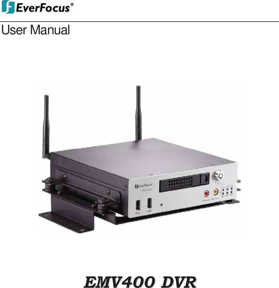
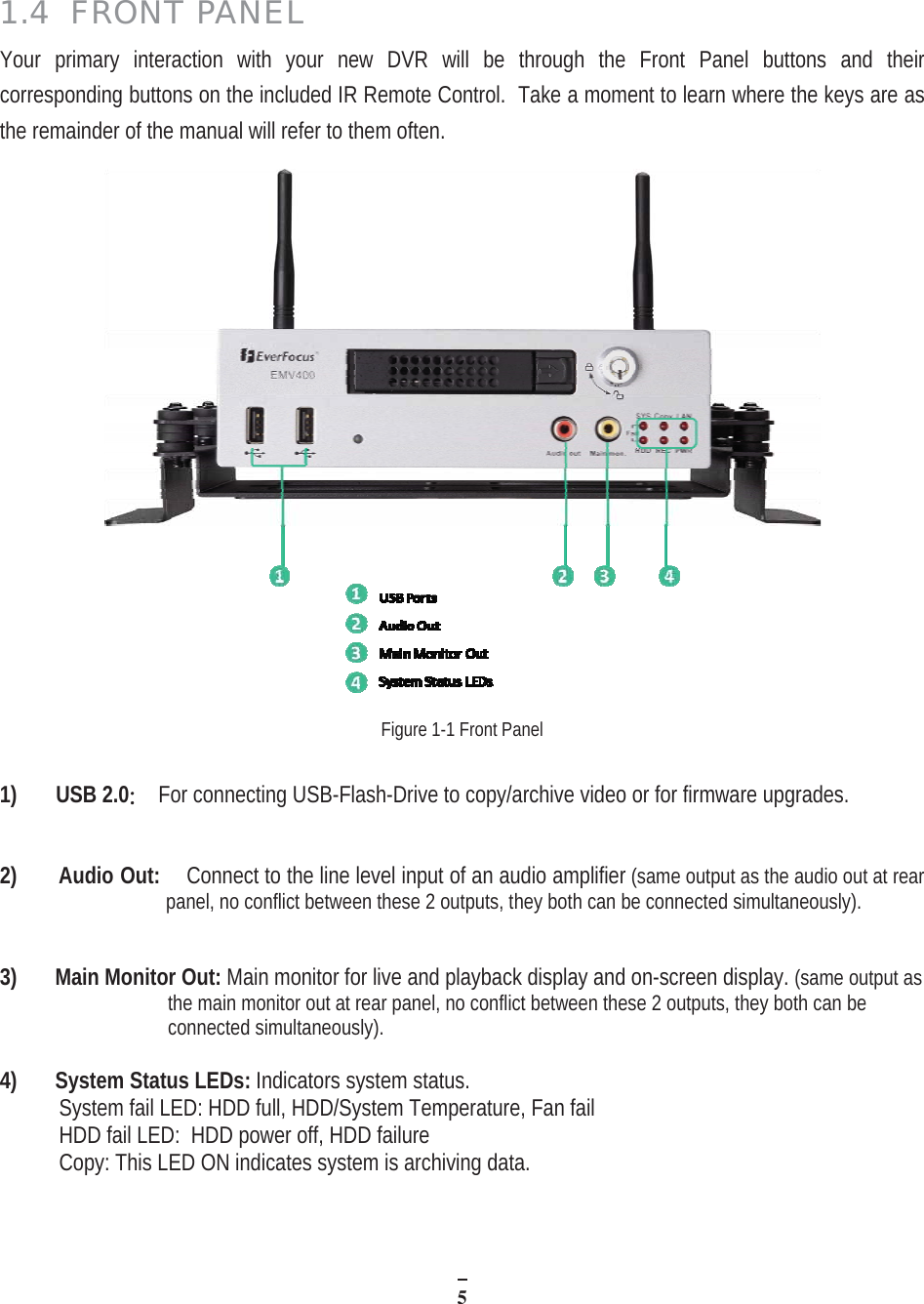
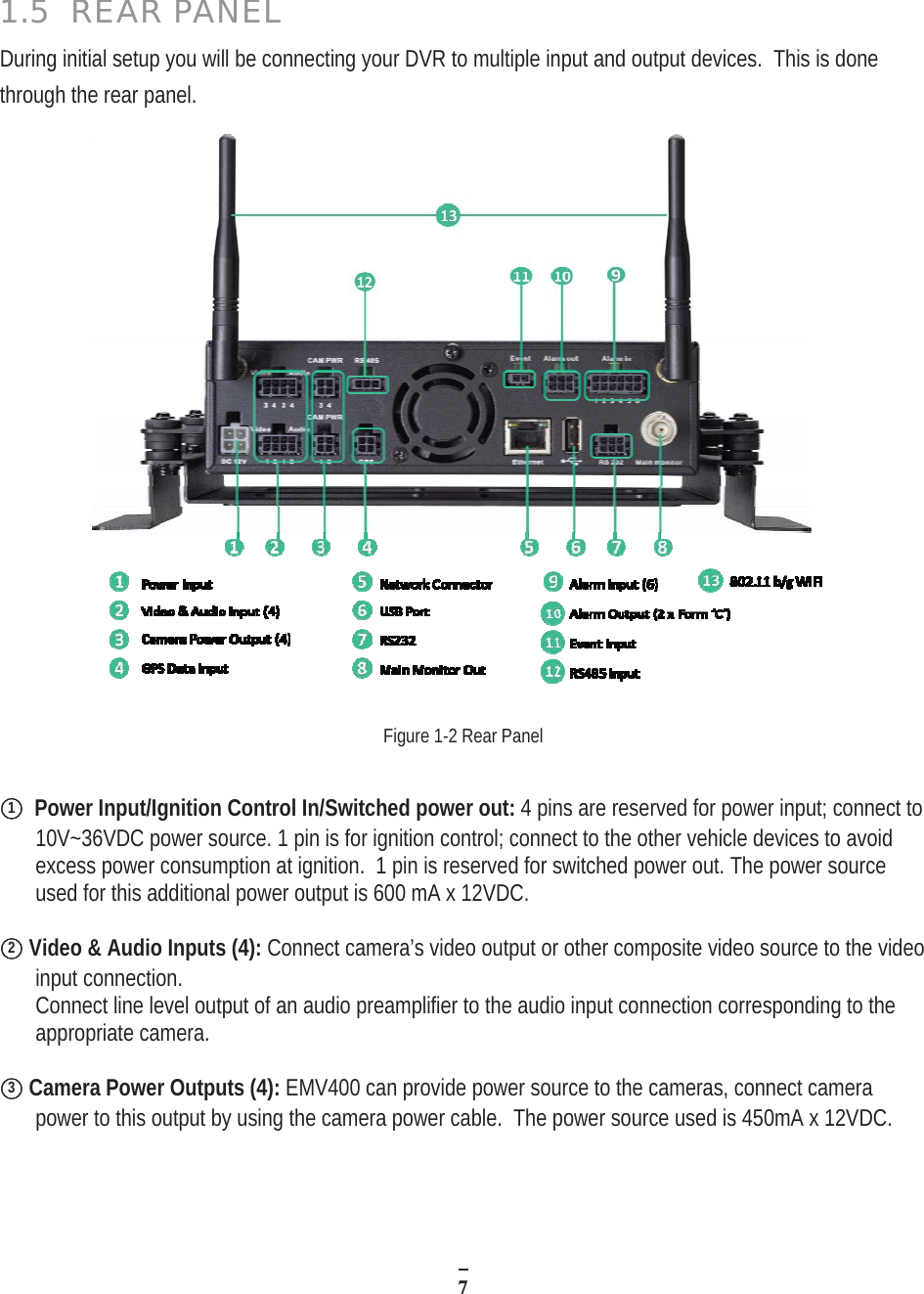
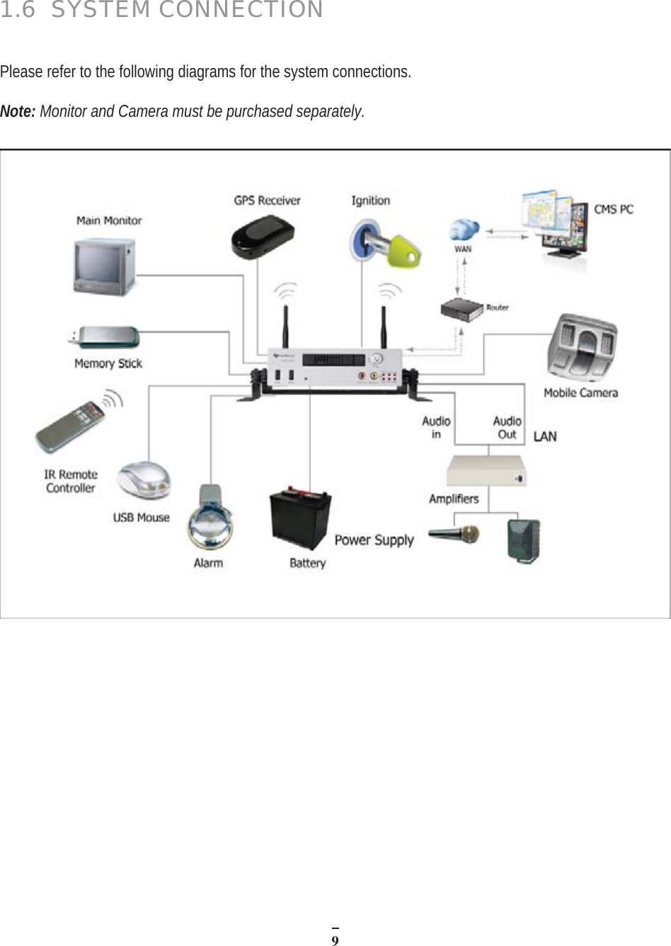
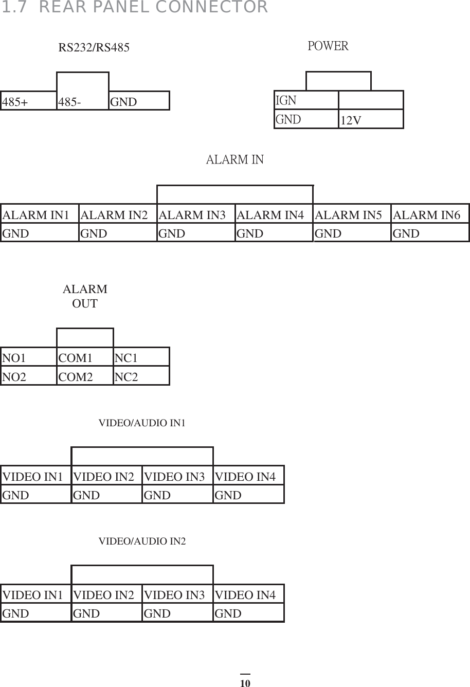
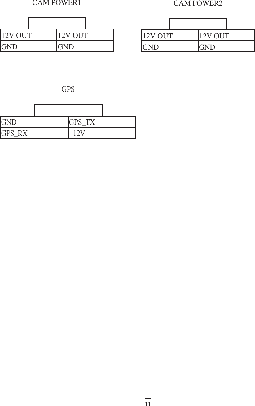
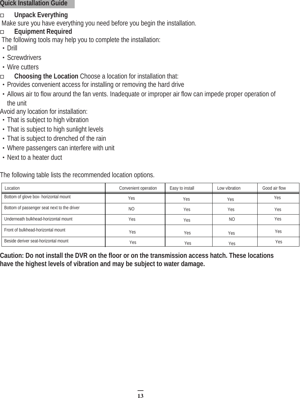
EMV400 W User Manual
Users Manual
Navigation menu
Upload a User Manual
Namespaces
Wiki Guide
HTML
PDF
Info
Views
User Manual
Discussion / Help
Navigation