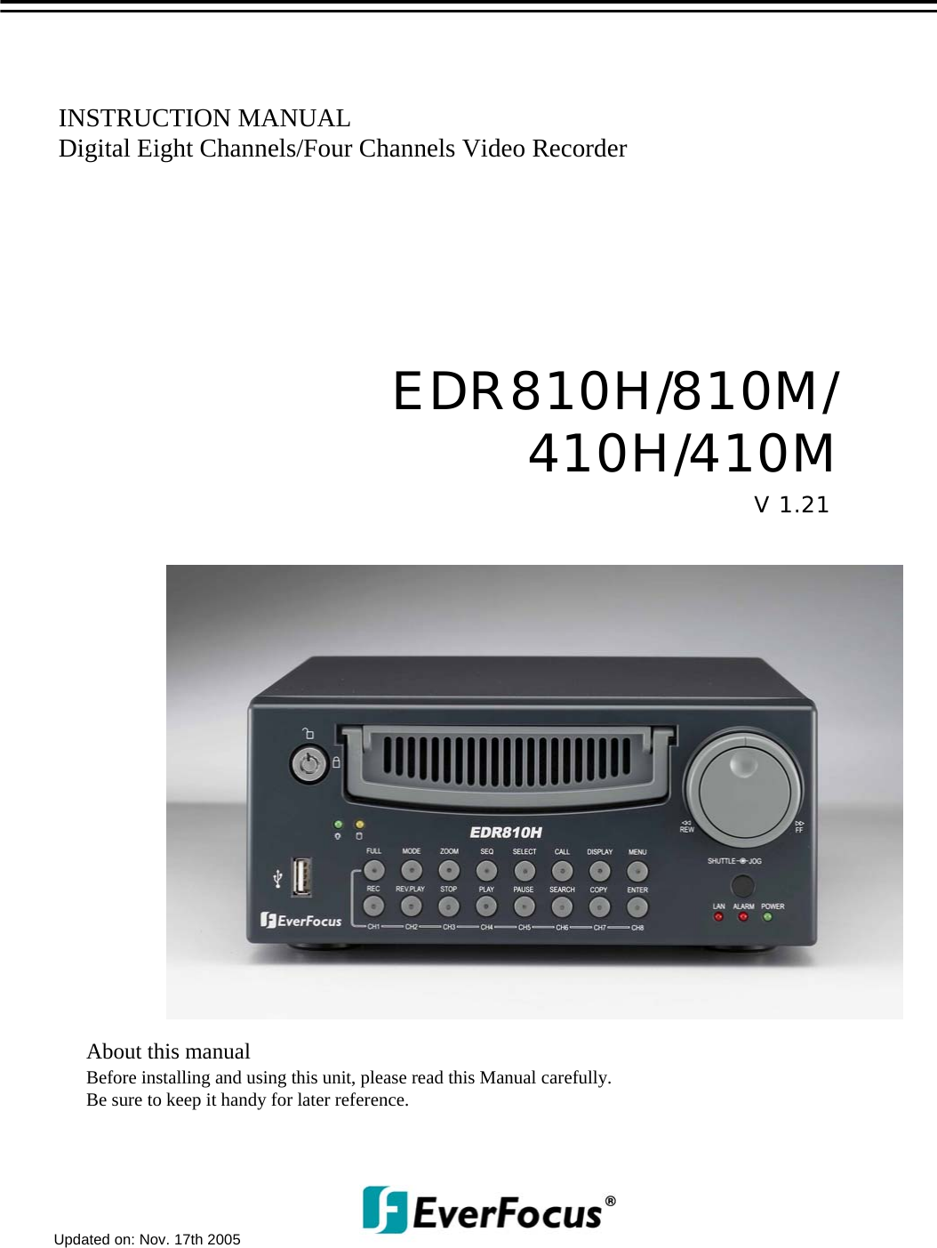
EverFocus Electronics EVEREDR810-410 Digital Video Recorder User Manual
EverFocus Electronics Corp. Digital Video Recorder Users Manual
UserManual.wiki
>
EverFocus Electronics
>
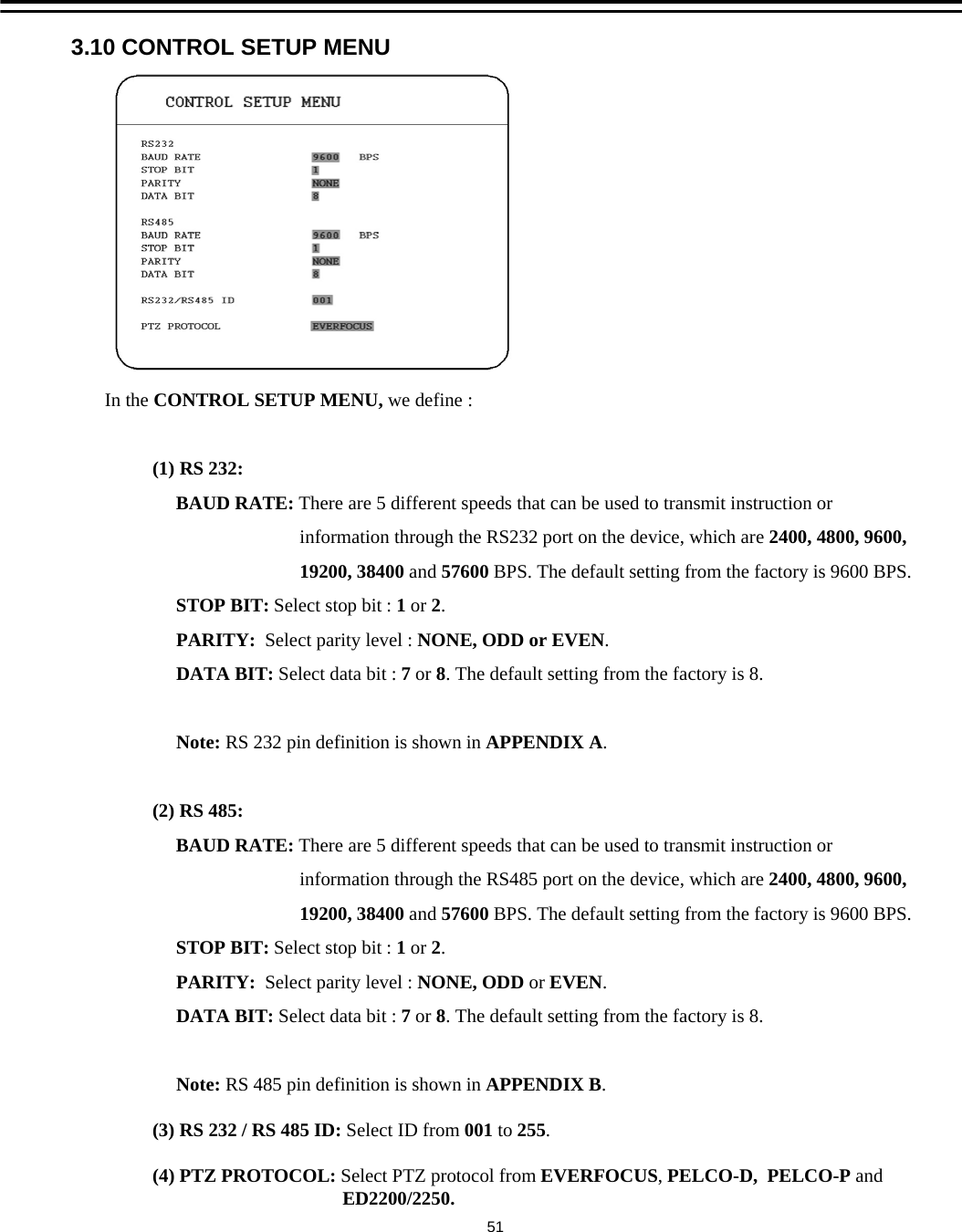
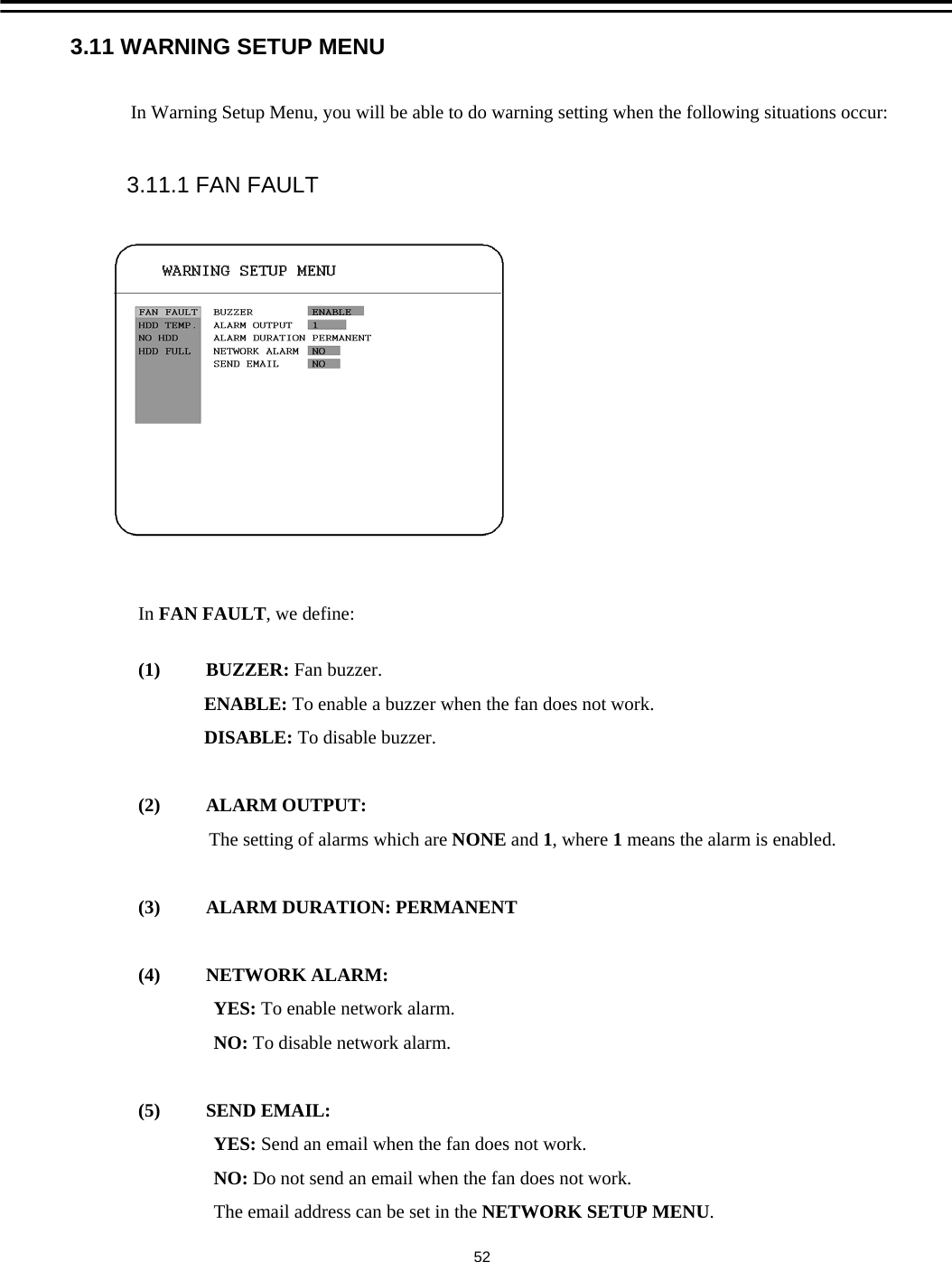
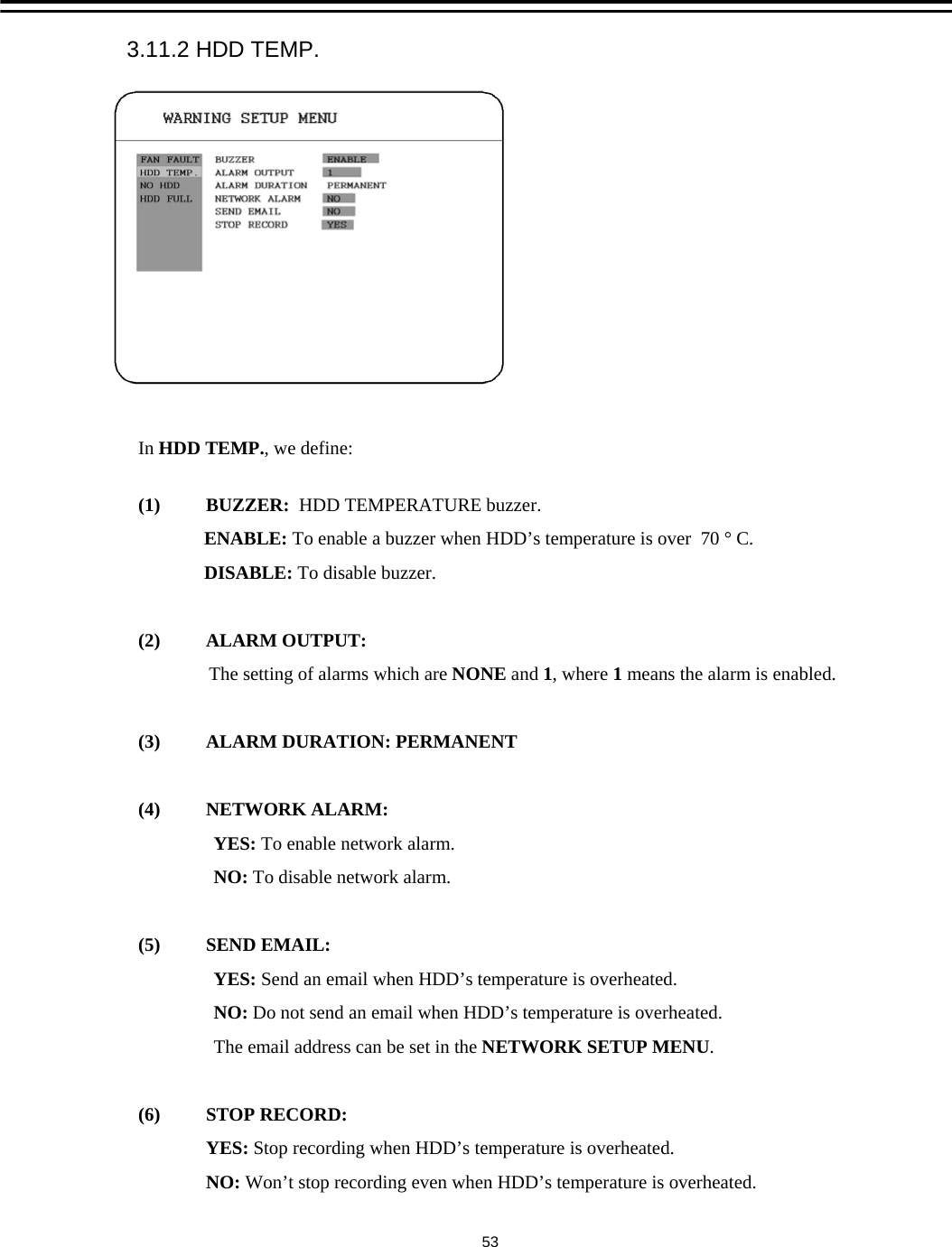
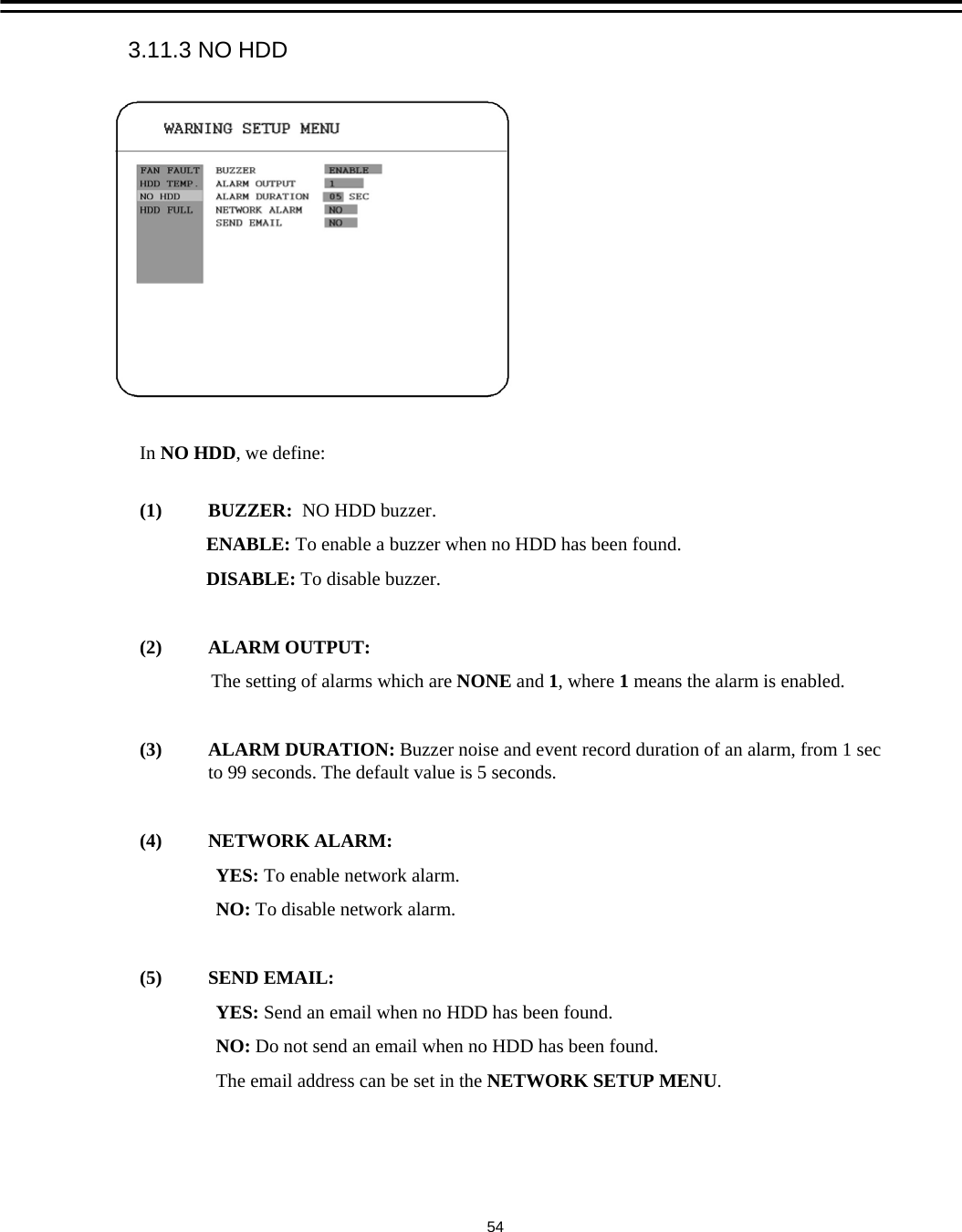
EVEREDR810 410 User Manual
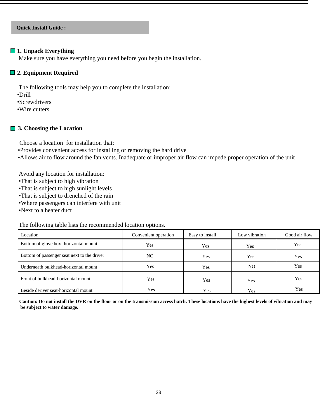
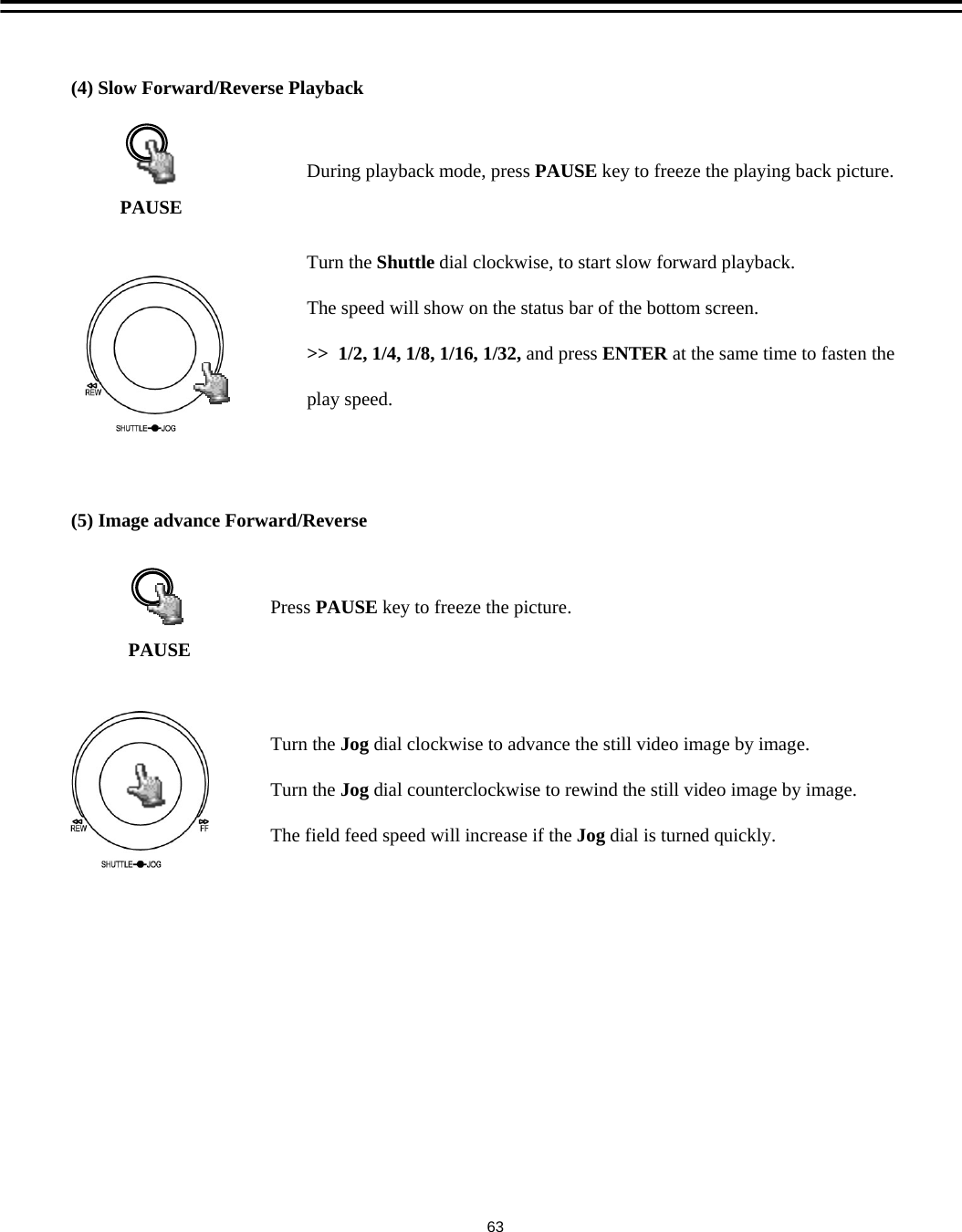
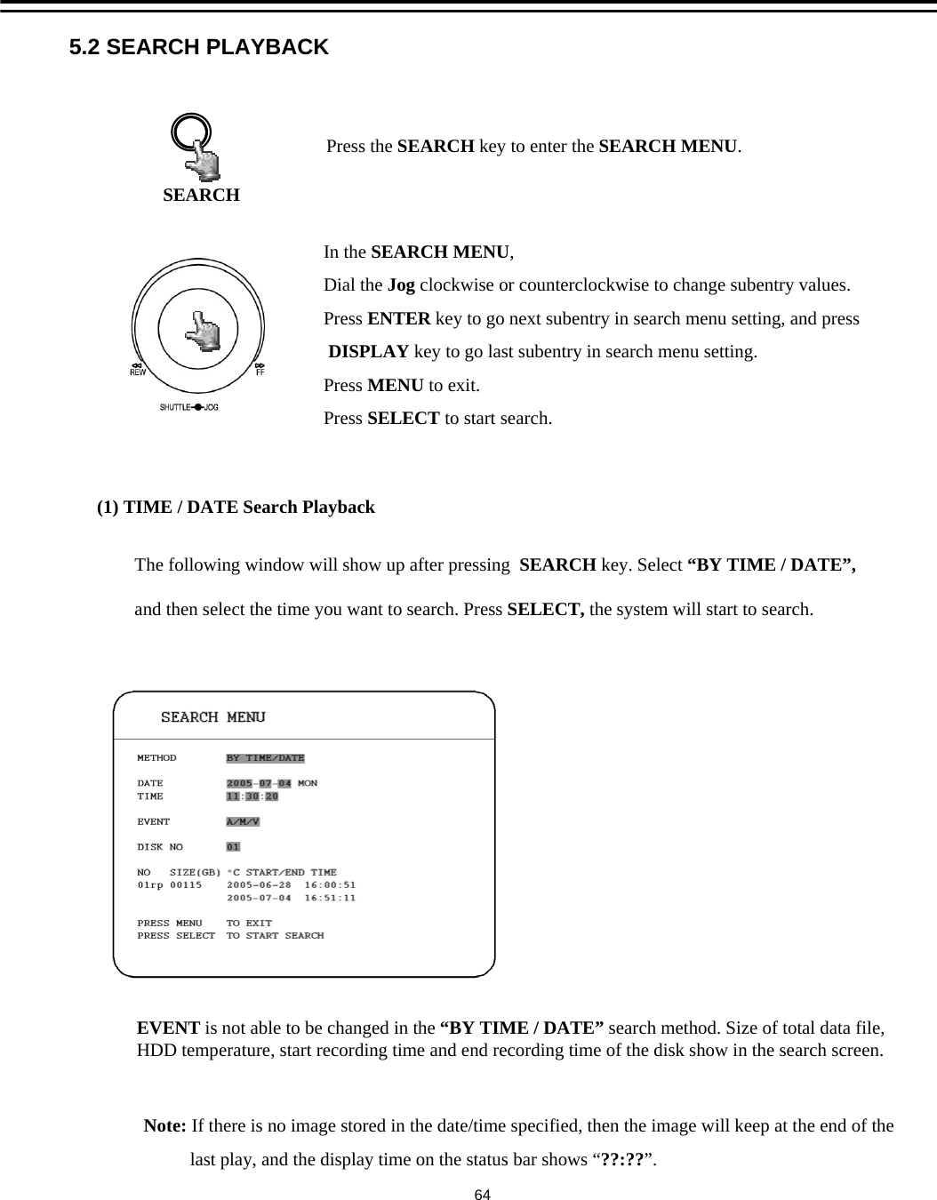
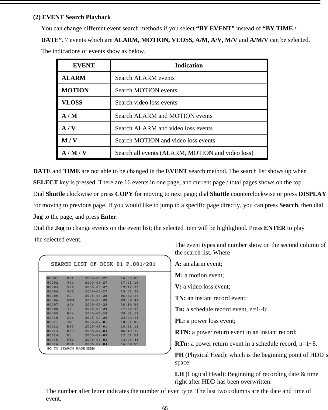
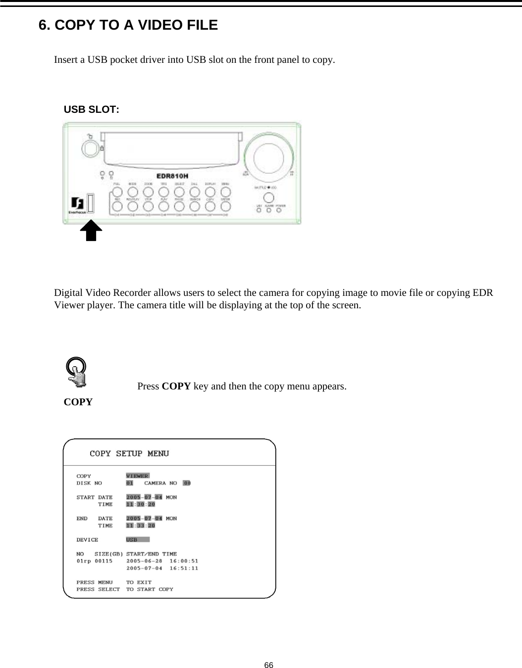
Users Manual
Navigation menu
Upload a User Manual
Namespaces
Wiki Guide
HTML
PDF
Info
Views
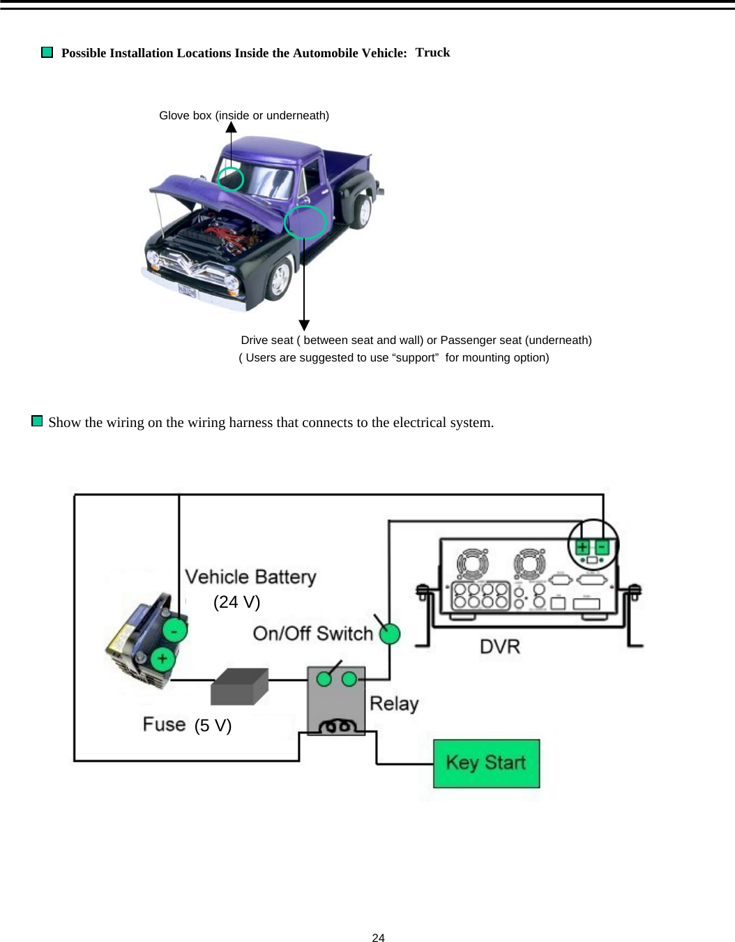
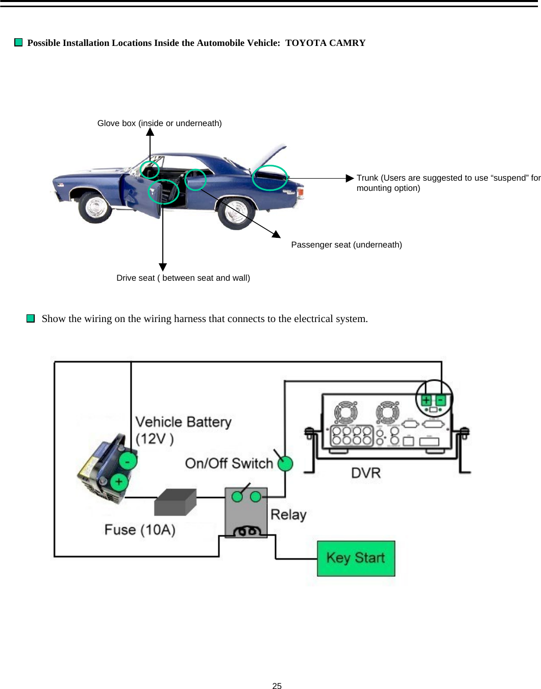
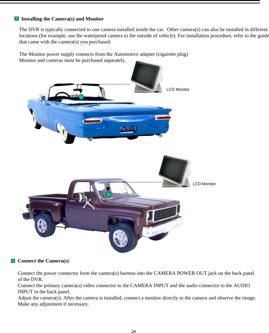
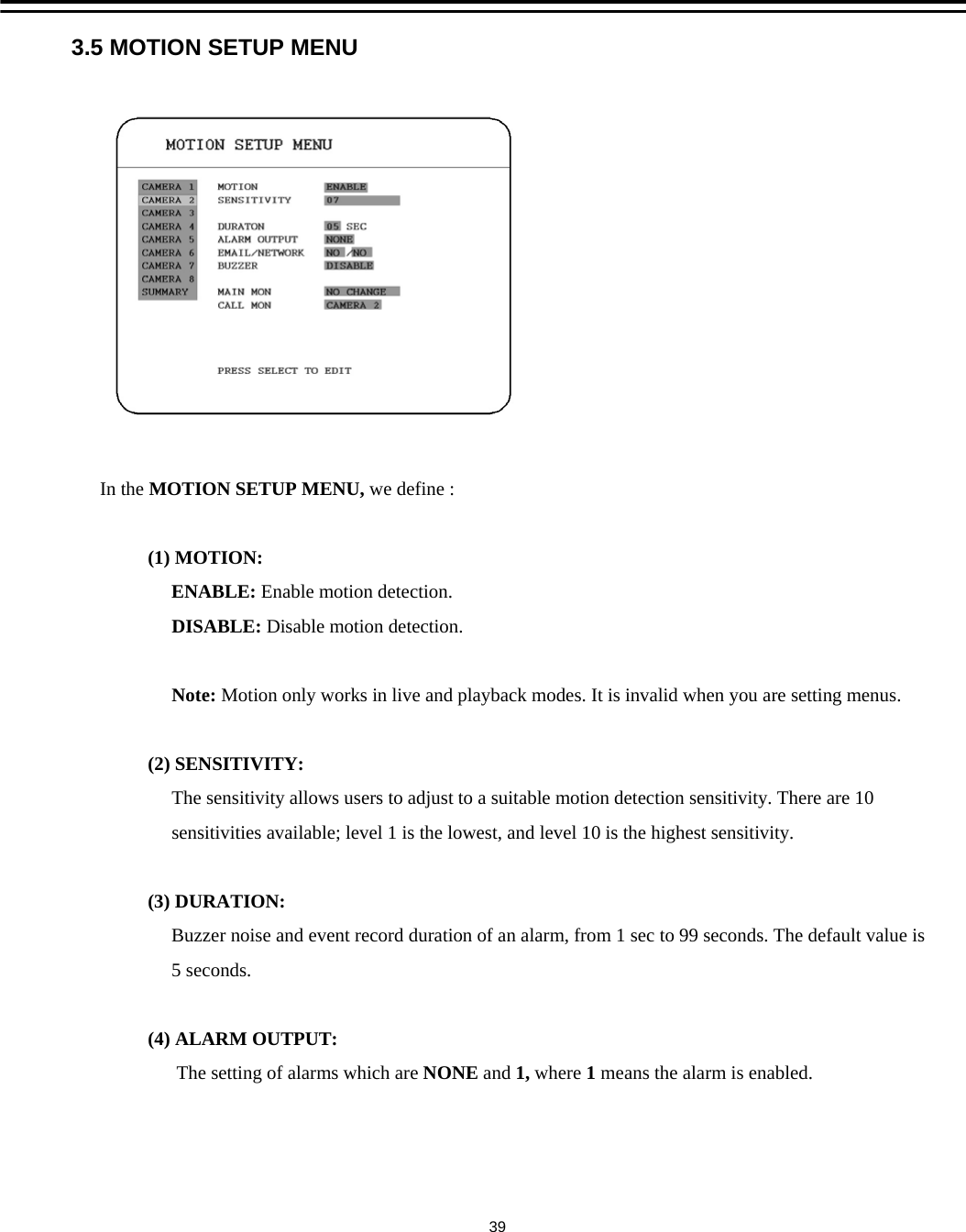
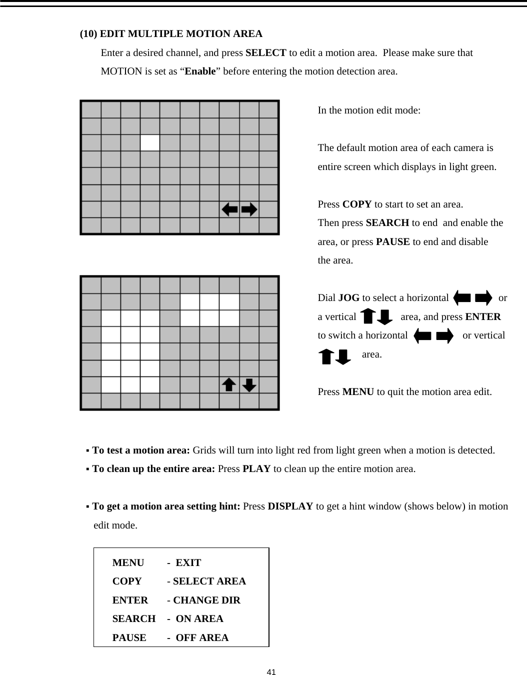
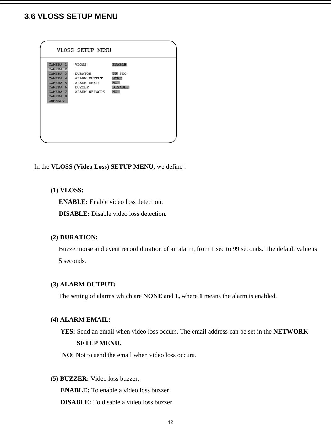
User Manual
Discussion / Help
Navigation