Everspring Industry Co AD145 Screw-in On/Off Module User Manual UserMan
Everspring Industry Co Ltd Screw-in On/Off Module UserMan
UserManual.wiki
>
Everspring Industry Co
>
AD145 User Manual
UserMan
Navigation menu
Upload a User Manual
Namespaces
Wiki Guide
HTML
PDF
Info
Views
User Manual
Discussion / Help
Navigation
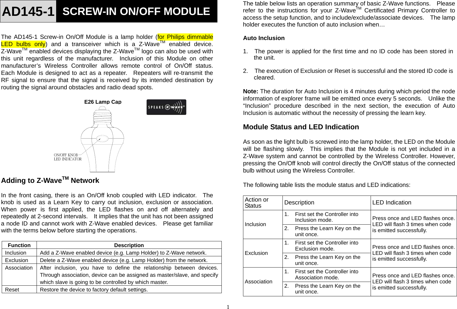
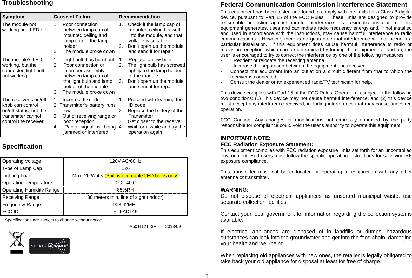
![2 Reset 1. Press the Learn Key 5 times within 5 seconds. 2. The Home ID and Node ID in the memory will be cleared and system will be restored to factory default. LED flashes 3 times. Empty No ID code memorized. On for 2 seconds & off for 2 seconds. Normal Normal operation mode. LED turns on/off according to the Module being on or off. Installation 1. Turn off the wall switch on the wall or mains power supply. 2. The lamp cap is E26. Choose the light bulb that fits the standard. 3. The Module is designed for ceiling mounting. Fit the Module into an existing lamp cap. 4. Place the light bulb into the lamp holder. Note: 1) The Module cannot be screwed in an air tight environment/ lamp stand. 2) The Module is suitable for use with Philips dimmable LED bulbs only. DO NOT connect non-lighting appliances to the Module or the connected load might be damaged. Operation To turn on or off the bulb controlled by the Module: z Simply press and release the On/Off knob. The red indicator LED will turn On/Off and the bulb screwed into the Module will also turn On/Off. z Dim function: Press and hold down the On/Off knob, after 2 seconds the brightness of the bulb will start to cycle. Release the knob when the brightness is right and the bulb will keep the setting. z With Z-Wave controller: simply press On or Off button on the controller. z With Z-Wave routing slave: Complete association between routing slave and the Module through Z-Wave controller, and the routing slave can control the On/Off status of Module. Programming 1. Z-Wave’s Groups (Association Command Class Version 2) 1-1. Group supported: The Module supports Group 1 (max. 5 nodes) 1-1-1. Power On Whenever power is applied, it will send ALARM_REPORT command to the nodes of Grouping 1 to inform associated devices that the Module is powered up. ALARM_REPORT Command [Command Class Alarm, Alarm Type = 0x02, Alarm Level = 0x01] Supported Command Class 1. COMMAND_CLASS_BASIC 2. COMMAND_CLASS_SWITCH_MULTILEVEL 3. COMMAND_CLASS_SWITCH_ALL 4. COMMAND_CLASS_MANUFACTURER_SPECIFIC 5. COMMAND_CLASS_VERSION 6. COMMAND_CLASS_ALARM 7. COMMAND_CLASS_ASSOCIATION_V2 E26/E27 lamp capLIGHT BULBE26 Lamp Cap](https://usermanual.wiki/Everspring-Industry-Co/AD145/User-Guide-2138879-Page-2.png)