Everspring Industry Co CA212 Remote control User Manual
Everspring Industry Co Ltd Remote control
User Manual
1
Figure 2
Fi
g
ure 1
C128W SOLAR CAMERA KIT
Installation and Operating Manual
Introduction
The Solar Camera is designed to economically provide safety,
security, convenience to your home and business. Its solar
panel collects daylight and maintains a charge to the battery of
the camera during daylight hours. A negligible amount of
energy is released by the rechargeable battery to operate the
camera during nighttime.
The components included in the C128W Solar Camera Kit:
● 1 x Solar Camera with PIR and Solar Panel (Transmitter)
● 1 x Audio & Video Receiver
● 1 x Power Adapter for Receiver
● 1 x 3 Feet RCA/SCRT Cable
● 1 x 6V 1.2A Rechargeable Battery
● 1 x 9V Alkaline Battery
● 1 x Waterproof Rubber Plug
● 1 X Remote Control
Caution
Pay attention to the following before you install:
1. Sufficient daylight: Solar panel
requires constant charge during
daylight hours. Please mount the
camera at the location that can
receive sufficient daylight exposure.
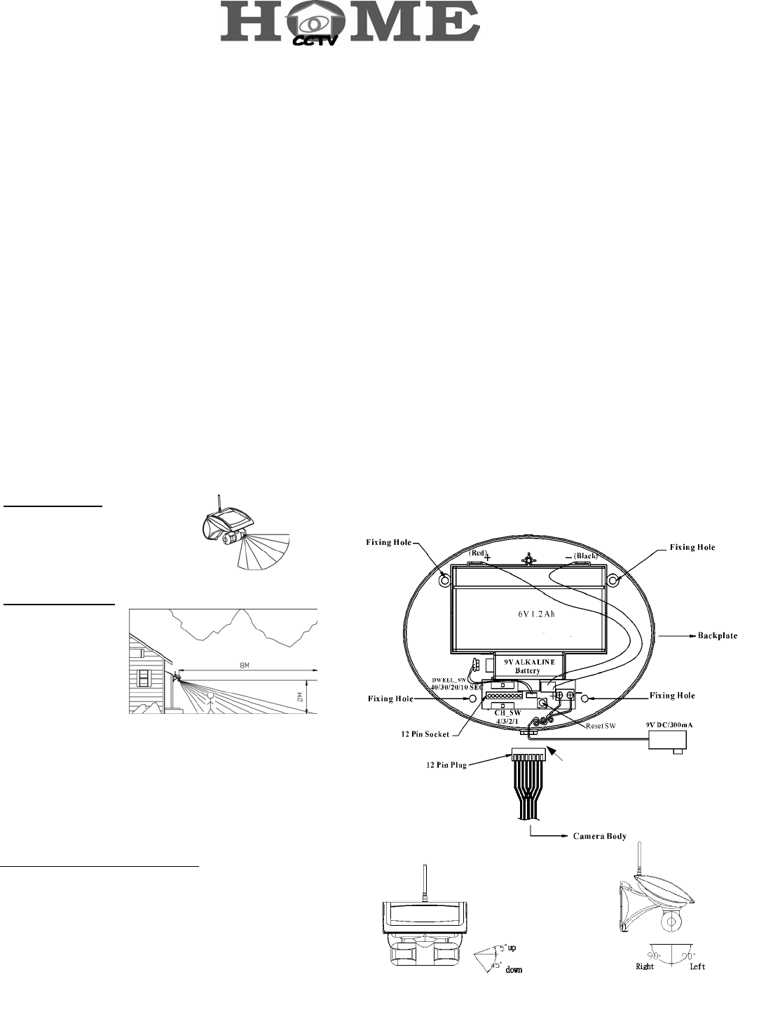
2. Detecting sensitivity: A passive
infrared sensor
operates by detecting
the objective
movement and heat.
When the temperature
of the moving object
and its surrounding
area are close in value, it may reduce
PIR’s sensitivity. The motion detector’s
infrared beams radiate outward like the slat of a wooden fence.
Prior to mounting, keep in mind that the motion sensor is more
sensitive to the motion that crosses these “slats”, and less
sensitive to the motion that moves directly towards the sensor
(see Figure 1 and 2.)
3.Keep a light source during nighttime: The camera cannot
work in total darkness. Please bear in mind the camera's
viewing area must be illuminated with a suitable light source
during nighttime.
Installation
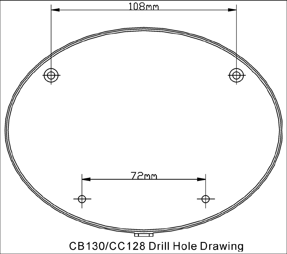
Step 1: Install the camera (refer to Figure 3)
a. Use the fixing template provided to mark the position of the
four fixing holes. Drill four 5mm-diameter holes.
b. Mount backplate by inserting two screws into fixing holes on
the top edge of backplate. (All electronic components are
housed within the backplate.)
c. Adjust the “DWELL_SW(SW3)” knob on backplate to set up
transmission time (lock time) of images and voices. It can be
set as 10,20,30 or 40 seconds.
d. Adjust the “CH_SW” knob on backplate to set up a channel.
And remember which channel you selected.
e. Plug the camera’s 12 Pin plug (Cable) into socket on the
backplate, then secure the camera set (front cover) to the
backplate by inserting screws into two fixing holes on the
button edge of front cover and backplate. And then insert
the waterproof rubber plug into the hole at the bottom of
front cover.
f. The camera and PIR which under the main solar panel
cabinet can be swiveled upward to 5°, downward to
45°(refer to Figure 4) and 90° horizontally (refer to Figure 5)
g. Adjust the camera and PIR angle according to your need.
Fi
g
ure 3
Figure 5
Figure 4
Waterproof Rubber Plug
2
Fi
g
ure 6 Euro
p
ean Version
Figure 7 American Version
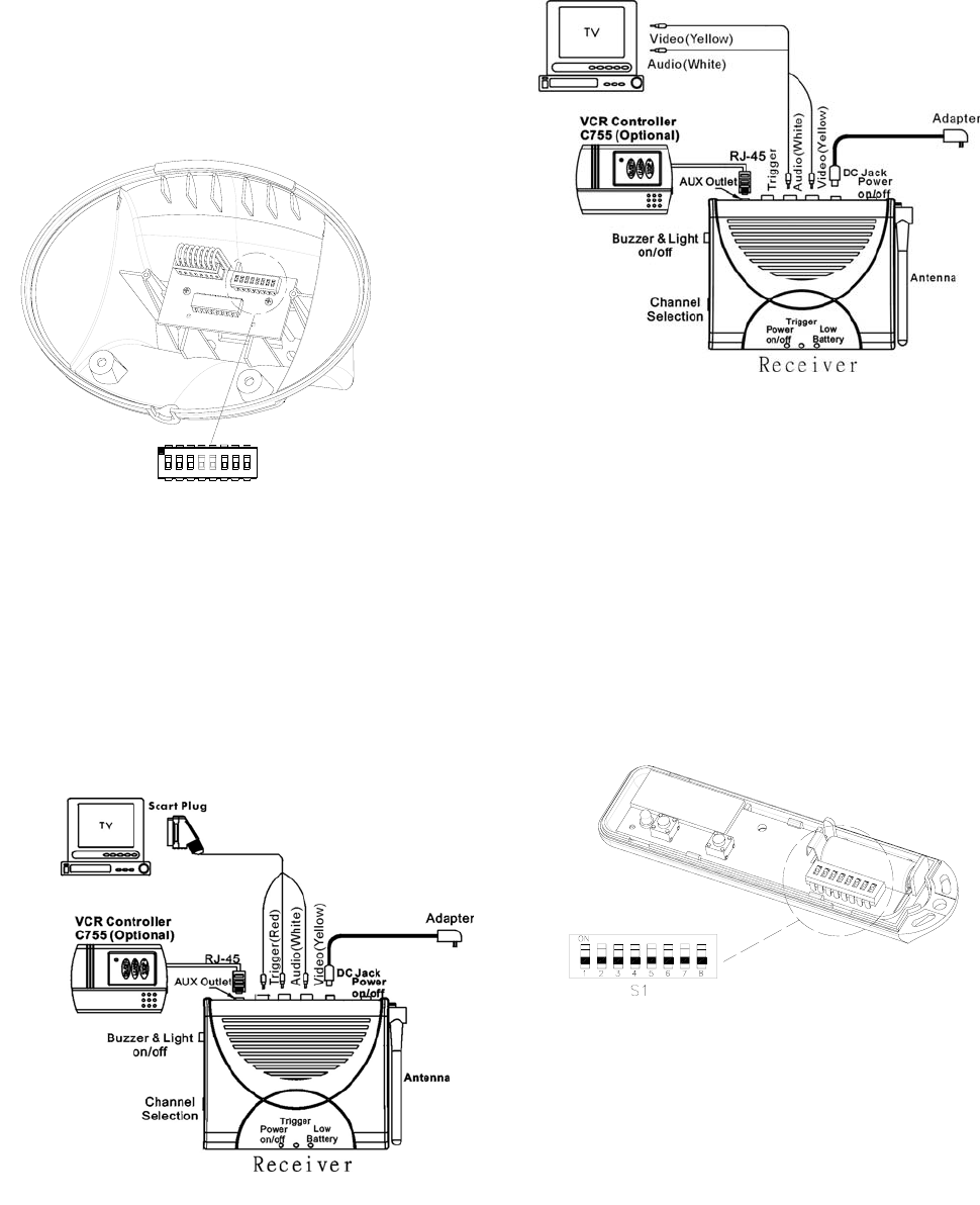
h. In order for the Remote Control to operate with the Camera
both devices must be configured with the same ‘House
Code’.
The House Code is configured by setting the 8 DIP switches,
located on the PCB in the rear of the main camera body, to a
random On/Off sequence. Use the tip of a ballpoint pen or
a small screwdriver to move each switch in turn and ensure
that each switch ‘clicks’ fully into position.
Note: it is recommended that the system House Code is
always reset to a code other than the factory default.
68751324
SW1
ON ECE
Step 2: Install Receiver Unit
(Two visions available: European and American)
European Version (refer to Figure 6):
To connect receiver to your TV:
1. Plug the 1M Scart connector cable that
package included into your TV.
2. Plug the other end, yellow (video), white (audio) and red
(trigger) RCA connectors into the corresponding RCA
connectors on the receiver.
American Version (refer to Figure 7):
To connect receiver to your TV:
1. Plug the yellow (video) and white (audio) RCA connectors
into TV socket.
2. Plug the yellow (video) and white (audio) RCA connectors
into the corresponding RCA connectors on the receiver.
Step 3: Install Remote Control
1. Remove the battery cover fixing screw on the rear of the
Remote Control and carefully remove the front cover.
2. Ensure that the House Code setting of the DIP switches in
the Remote Control are set to the same On/Off sequence
as set on the Camera.
3. Insert the battery taking care to observe the correct polarity.
4. Replace the front cover and refit the fixing screw. Do not
over tighten the screw as this could damage the screw
thread in the moulding.
Operating Instruction:
(1) Buzzer/Light ON/OFF SW: Select “Buzzer/Light SW” at
"ON". When PIR camera is triggered, image and voices
will be transmitted. Upon receiving the signals, the receiver
sounds “Beep” twice in response and the LED will flash for
1 minute.
(2) Transmission time (lock time) of image and voices can be
set as 10, 20, 30, or 40 seconds by carefully adjusting the
“DWELL_SW (SW3)” knob of Camera.
(3) When lock time of trigger is over, the camera will continue
3
transferring image and voices if PIR sensor is still under
triggered condition. Otherwise, the camera will send an
“OFF” signal to the receiver and shut down images and
voices.
(4) When PIR of the camera is triggered, the camera will send
2.4GHz RF signal to the receiver. Thus, images and voices
will be displayed on TV or monitors through the receiver.
(5) When battery is low:
a. In the condition of camera on, Camera sends a signal to
the receiver to lighten the “Battery” LED and sound two
“beeps” for alert.
b. If battery is low during image transmitting, the image will
stay on for 5 seconds only. Then there will be two beeps
and the “Battery” LED will be on.
(6) If the camera battery is recharged to normal level, the low
Battery LED will be turned off when the camera is
triggered again.
You can also additionally have a 9V DC 300mA regulator power
AC adapter and wire it on S3 (refer to Figure 3) of backplate to
recharge and to transmit images and voices continuously.
Note:
(1) What you should do when the camera does not work
properly:
a. Unscrew the camera (two screws on the edge of front cover)
b. Press “SW1” on Wall Mount to restore the system
c. Turn off the receiver, then turn it on.
d. Hang the camera on Wall Mount, and tighten 2 screws on
the bottom of the camera.
(2) When battery is low, video automatically reduces to 5
seconds to save battery.
(3) Position the receiver and set up channel first while installing,
then position the camera and set receiver in the same
channel with the camera.
(4)When the image on TV is not clear, it means that somebody
may use the same channel as yours in your neighborhood.
You can change both channels on the backplate of camera
and the receiver. Remember to set the camera in the same
channel as that of the receiver.
4
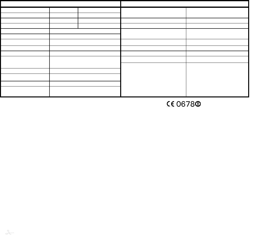
SPECIFICATIONS
CC128 CA117
Camera Type CC128
Picture Type Color CMOS
Operating Frequency 2400-2483MHz (for 4 channels)
TV System PAL/NTSC Transmission Range 75m in open space
Sensitivity 3Lux@F1.2 Channel Selection Switch 4 positions for 1~4 selection
Lens Angle 78° Diagonal
Lens 4.3mm F2.0
Buzzer & Light Switch 3 positions for buzzer & light on
/ buzzer off/off
Camera Angle Left & Right 90°± 5°, Down 45° Power Switch 2 positions for power on/ off
Microphone Build in Triggered Buzzer & Light function Build in
Transmitting Frequency 2400~2483MHz (for 4 channels) Antenna Type Rod
AC Adapter 12VDC, 500mA AC adapter
Battery 1 x 9V back up battery, 1x 6V
rechargeable solar battery
Dwell Time Switch 4 positions for 10s/20s/30s/40s
Power Supply Source Solar Panel (110*160mm)
Channel Switch 4 positions for 1~4 selection
PIR Detect ion
Distance/Angle 8M/90° (under 28°C)
Connector 1 x RJ-45 for VCR Controller
1 x DC Jack for Power
3 x RCA Jack for triggered(red),
audio(white), video(yellow)
© 2002 Everspring Industry Co., All Rights Reserved
…………………………………………………………………………………………………………………………………………..……
Federal Communication Commission Interference Statement
This equipment has been tested and found to comply with the limits for a Class B digital device, pursuant to Part 15
of the FCC Rules. These limits are designed to provide reasonable protection against harmful interference in a
residential installation. This equipment generates, uses and can radiate radio frequency energy and, if not installed
and used in accordance with the instructions, may cause harmful interference to radio communications. However,
there is no guarantee that interference will not occur in a particular installation. If this equipment does cause
harmful interference to radio or television reception, which can be determined by turning the equipment off and on,
the user is encouraged to try to correct the interference by one of the following measures:
- Reorient or relocate the receiving antenna.
- Increase the separation between the equipment and receiver.
- Connect the equipment into an outlet on a circuit different from that to which the receiver is connected.
- Consult the dealer or an experienced radio/TV technician for help.
This device complies with Part 15 of the FCC Rules. Operation is subject to the following two conditions: (1) This
device may not cause harmful interference, and (2) this device must accept any interference received, including
interference that may cause undesired operation.
FCC Caution: Any changes or modifications not expressly approved by the party responsible for compliance could
void the user's authorit
y
to o
p
erate this e
q
ui
p
ment.
D/NL/F/E/B/S/CH
5