Everspring Industry Co CC420 Baby Camera User Manual 8697366
Everspring Industry Co Ltd Baby Camera 8697366
Users Manual
1
Installation and Operating Instruction
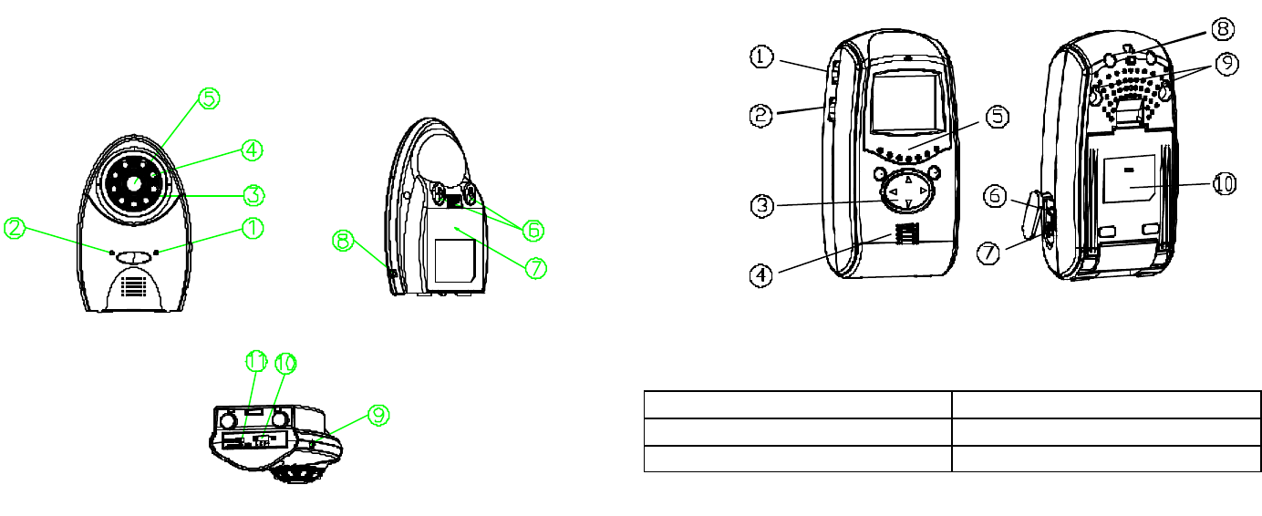
Product Layout
Camera (Fig. 1)
? Low battery indicator LED
? Power indicator LED
? Microphone
? Infrared LEDs
? Lens
? Keyholes
? Battery compartment
? 6V DC power adaptor plug
? A/V IN
? Channel selection switch
? Night/color/power off switch
Fig. 1
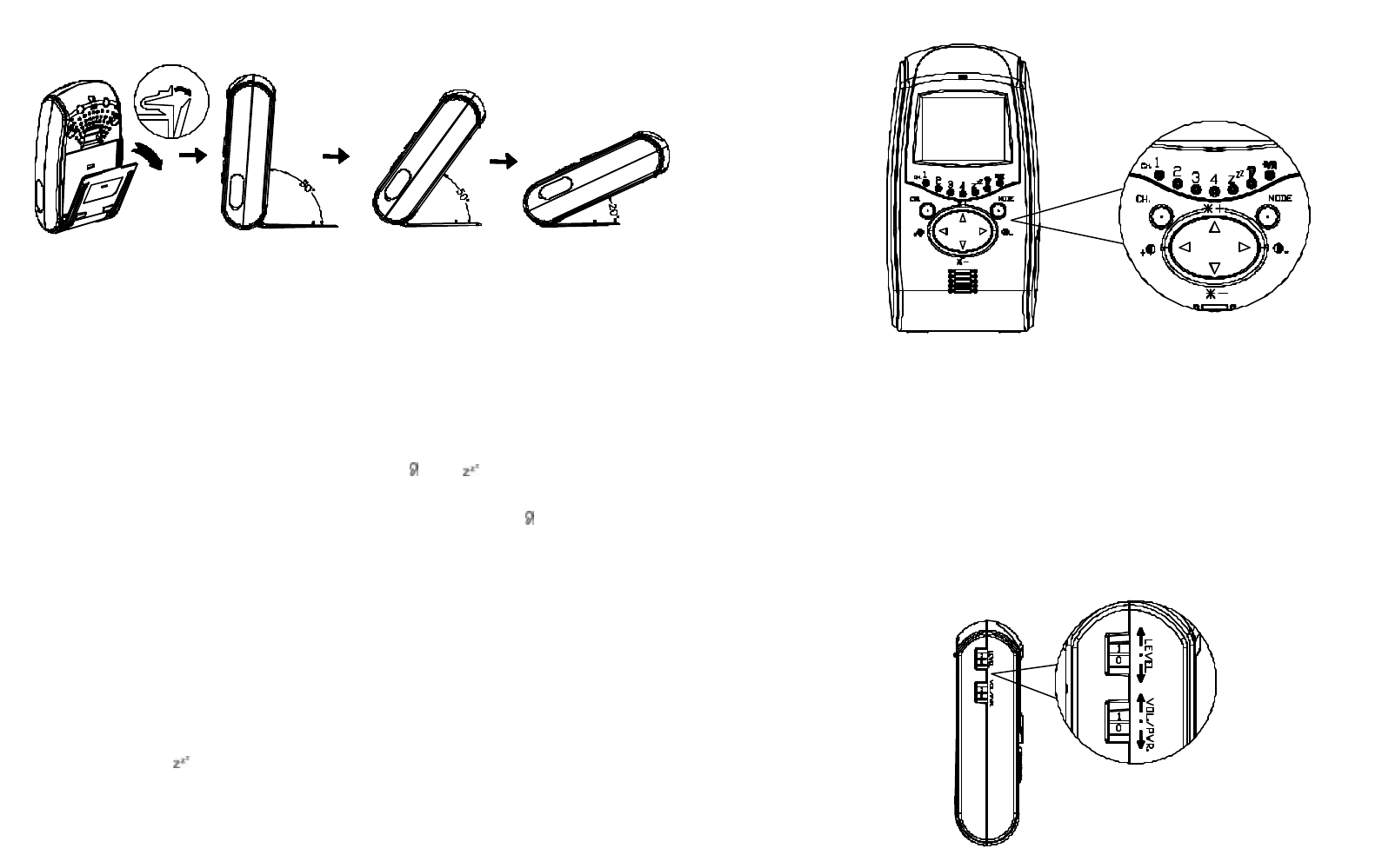
Monitor (Fig. 2)
? Sensitivity level control
? Volume/power control
? Brightness/contrast ratio control
? Speaker
? LEDs indicator
? A/V OUT
? 6V DC power adaptor plug
? Hang up hole
? Keyholes
? Swiveling pivot
Fig. 2
Kit Content
1 x Camera 2 x AC Adaptor
1 x Monitor All Fixing Screws
2 x A/V cable This manual
2
Introduction
This package is designed to facilitate the users who intend constant
observation of the particular place where continuous caring or surveillance is
needed. Both Camera and Monitor units are suitable for indoor use only.
Either 4 AA-size batteries or an AC adaptor can be used as their power source.
When the battery level falls below an acceptable level, the “LOW BATTERY”
indicator on the front of the Camera and Monitor will light up. When this occurs
the batteries should be replaced as soon as possible.
Setting Up the Camera
Power Supply
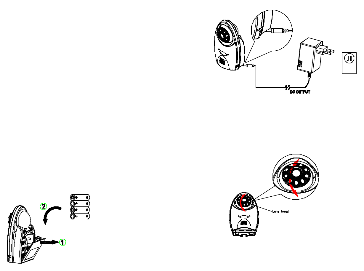
The Camera adopts either 4 AA-size batteries (no supplied) or the AC adaptor.
Loading the Batteries
1. Open the battery compartment cover on the rear of the camera.(Fig. 3)
2. Insert 4 AA-size batteries, ensuring that correct polarity is put. (Fig. 3)
3. Refit the battery compartment cover and make sure it is locked securely.
Note: Never mix old batteries with new ones.
Remove the batteries from the Camera if you do not plan to use it for a
long period of time.
Fig. 3
Using the AC adaptor
Plug one end of the provided power adaptor into a wall outlet and the other end
into the Camera. (Fig. 4)
Fig. 4
Installing the Camera
The Camera is suitable for mounting in dry interior locations only. 3 types of
installation can be made, such as wall mount, table stand or clip-on the crib.
Place the Camera in a convenient location, point the lens towards the
observed area and adjust the angle by adjusting the lens head vertically. (Fig.
5)
Fig. 5
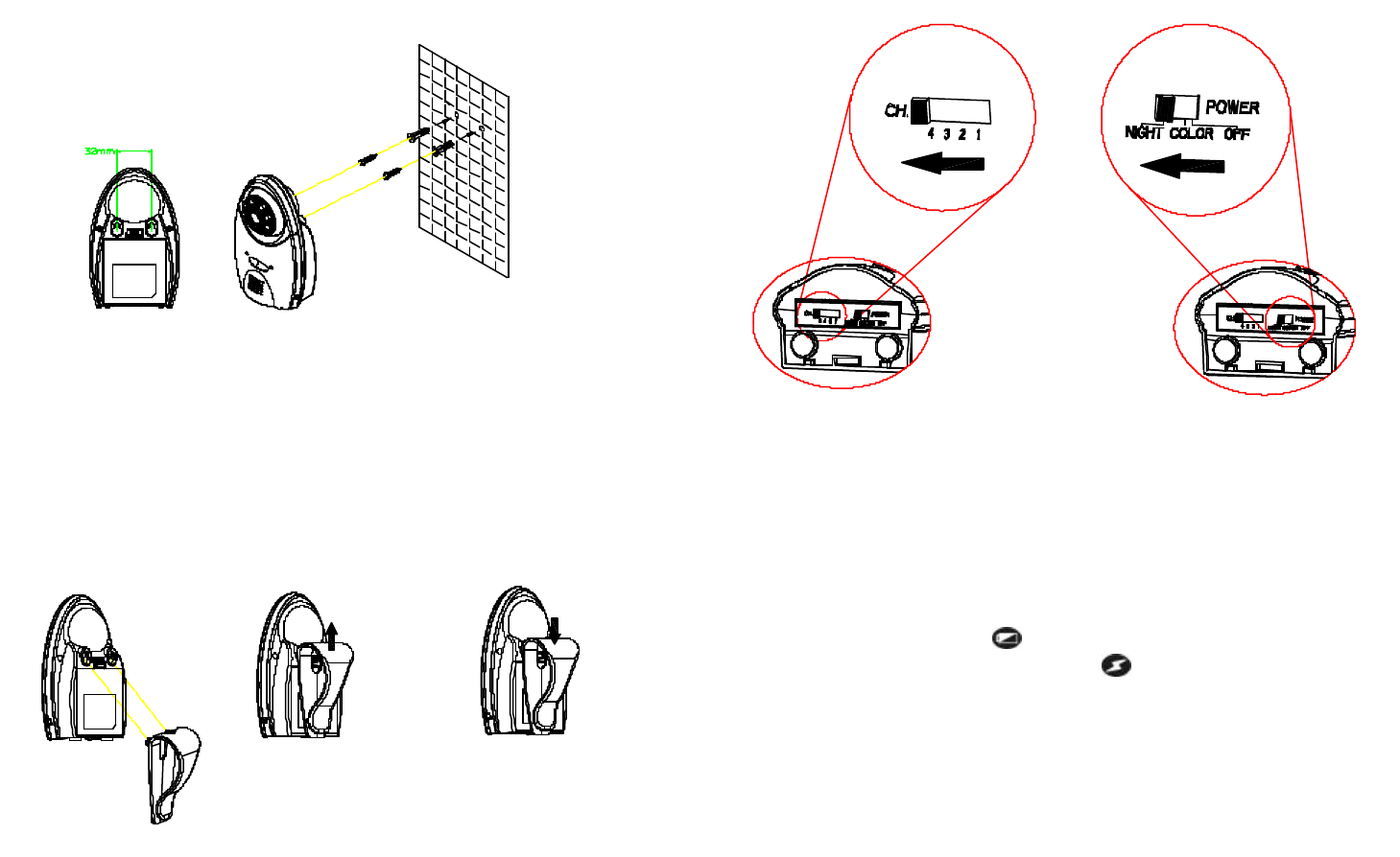
Wall Mounting the Camera
Note: The Monitor reception should be tested before fixing the camera in place.
Ideally you will need someone to hold the Camera against the wall in the
selected mounting area while you check the reception on the Monitor. If
interference or other problems occur, refer to the Troubleshooting. You may
need to select a different location in the room for mounting the Camera.
3
1. Decide on the appropriate mounting location. Drill two holes 32mm apart in
a line and fit wall plugs. (Fig. 6)
2. Insert fixing screws until almost fully home and hang the Camera over
these screws using the two keyhole slots in the rear of the Camera. (Fig. 6)
Fig. 6
Clipping on the Camera
1. Use the clip as supplied for fixing the Camera on the crib or table edge.
(Fig. 7)
2. Place the clip to the two slots on the top of Camera and lift it up to fit it in
place. (Fig. 7)
Note: For removing the clip, push the clip downward. (Fig. 8)
Fig. 7 Fig. 8
Operating the Camera
1. Set the channel switch (numbered 1~4) that matches to that of the Monitor
you plan to observe. (Fig. 9)
Fig. 9
Note: If more than 2 cameras are in use, do not set the same channel at
the same time.
2. In the daytime, slide the NIGHT/COLOR/OFF switch to the COLOR
position, so that colorful image will be revealed on the Monitor. (Fig. 9)
3. In the nighttime where ambient light level is insufficient, slide the
NIGHT/COLOR/OFF switch to the NIGHT position for monochrome image
display. (Fig. 9)
4. When the low battery LED lights up, replace batteries immediately.
5. Under normal operation, the power LED should be on.
Setting Up the Monitor
Power Supply
The Monitor uses either 4 AA-size batteries (not supplied) or the AC adaptor.
Note: When replacing batteries or connecting to the AC adaptor, turn off the
Monitor.
4
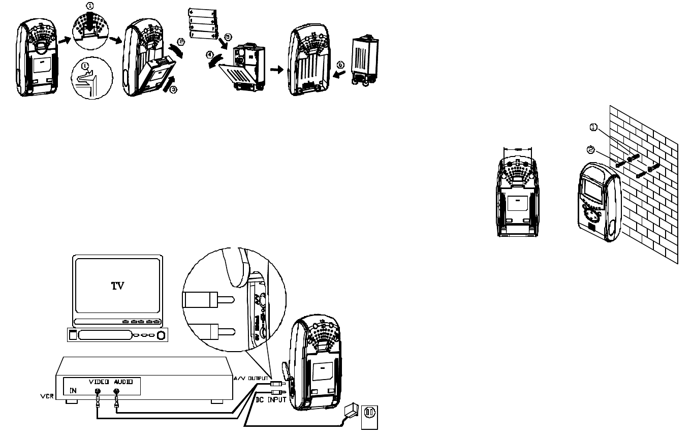
Loading the Batteries
1. Remove the power cavity from the rear of the Monitor. (Fig. 10)
Fig. 10
2. Open the battery compartment cover and fit 4 AA-size batteries, following
+ and – signs as indicated on the inside battery compartment. (Fig. 10)
3. Close the battery compartment cover and refit the power cavity in place.
(Fig. 10)
Using the AC Adaptor
Plug one end of the provided power adaptor into a wall outlet and the other end
into the side of Monitor. (Fig. 11)
Fig. 11
Installing the Monitor
3 types of installation can be made, such as wall mount, table stand and hang
up by string.
Wall Mounting the Monitor
1. Decide on the appropriate mounting location. Drill two holes 48mm apart in
a line and fit wall plugs. (Fig. 12)
2. Insert fixing screws until almost fully home and hang the Monitor over
these screws using the two keyhole slots in the rear of the Monitor. (Fig.
12)
Fig. 12
Table standing the Monitor
The Monitor has the swiveling pivot which allows flexible angle adjustment for
table standing installation.
1. Adjust the swiveling pivot to an appropriate angle for best viewing
condition. (Fig. 13)
Note: To meet various applications, the angle of swiveling pivot can attain
80°, 50° or 20°.
2. Place the Monitor to an ideal location.
5
Fig. 13
Hanging up the Monitor
On the top of the rear of Monitor, penetrate a string through the hole.
Operating the Monitor
1. Upon reception from the Camera, 3 modes can be selected by pressing
the mode selection button on the front of Monitor.
a. Audio/video mode: The Monitor is on continuously, emitting sound
and image. Under this mode, both and LEDs will not illuminate.
(Fig. 14)
b. Audio mode: The Monitor only delivers audio and LED will light up.
(Fig. 14)
c. Audio-activated mode:
This audio-activated mode allows you to set the sensitivity of audio
level that will trigger the Monitor. To use audio-activated function,
follow these steps:
c-1: Set the sensitivity control on the Monitor to the level you prefer.
Note: The sensitivity level can vary between 0 to 9. A value of 0
gives minimum sensitivity, a value of 9 gives maximum sensitivity.
c-2: Press the mode selection button on the front of the Monitor until
the LED lights up.
c-3: When the sound from the Camera reaches the set level, the
Monitor will turn on automatically, accompanying two beeps and
image. It will turn off automatically after 30 seconds.
c-4: Pressing the Brightness/Contrast Ratio control will turn on the
Monitor for impromptu surveillance.
Fig. 14
2. Volume/Power control: It allows you to adjust the audio level received from
the Camera. (Fig. 15)
Note: The audio level can vary between 0 to 9. A value of 0 gives
minimum level, a value of 9 gives maximum level.
3. Channel selection: 4 channels are available by pressing CH selection
button on the front of the Monitor. The channel sequence will be rotated
once by pressing the button each time. (Fig. 14)
Fig. 15
6
4. Brightness/Contrast Ratio Control: The brightness and contrast ratio
control for the Monitor can be adjusted by pressing the below button: (Fig.
14)
: Increase brightness
: Reduce brightness
: Increase contrast ratio
: Reduce contrast ratio
5. When the battery level drops, the LED will be in red. Battery
replacement should be taken as soon as possible. If everything is ok, the
LED will be in green.
Other Applications
Recording on a VCR / Monitoring from a TV
1. The Monitor comes with an A/V output jack for connecting to a TV or VCR
for monitoring/recording. (Fig. 16)
2. Connect the mini plug of the provided A/V cable to the A/V jack on the side
of the Monitor. Connect the other end of the cable to the A/V jacks of the
A/V components labeled LINE IN. (Fig. 16)
3. The Monitor serves as a receiver to receive the RF A/V signal from the
Camera or other A/V device for recording or displaying.
Fig.16
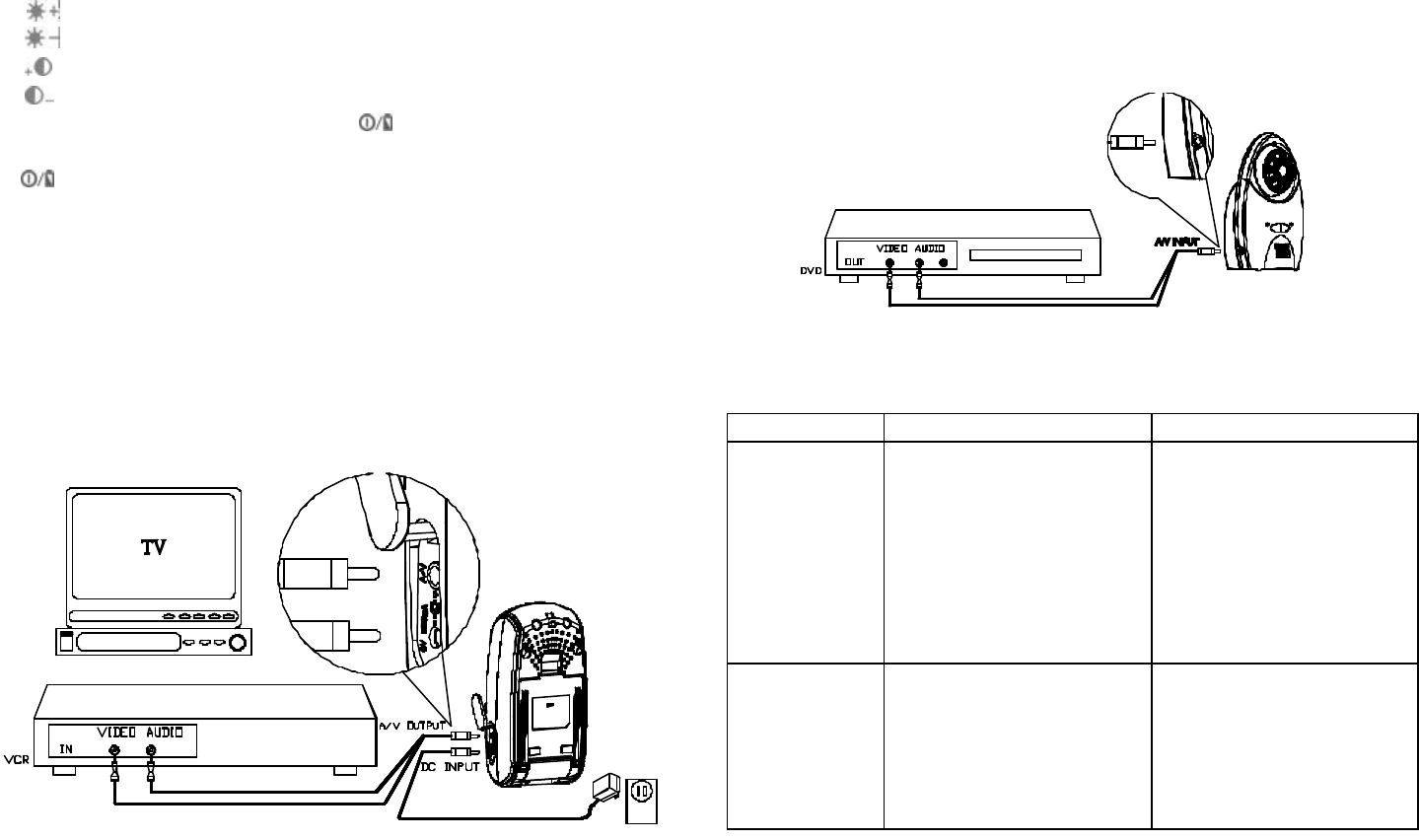
Serving as an A/V Sender
1. The Camera comes with an A/V input jack for connecting to a DVD/video
device for signal transmission. (Fig. 17)
2. Connect the mini plug of the provided A/V cable to the A/V jack on the side
of the Camera. Connect the other end of the cable to the A/V jacks of the
A/V components labeled LINE OUT. (Fig. 17)
3. The Camera serves as an intermedium to emit the image and sound from
a DVD/video device via 2.4GHz RF technology to the Monitor.
Fig. 17
Troubleshooting
Status Possible Cause Remedy
Power indicator
LED does not
light up
a. Reverse polarity
b. Run out of battery
c. Wrong polarity on DC
adaptor plug
a. Follow the polarity
shown inside the battery
compartment for loading
the batteries
b. Replace new 4 AA-size
batteries
c. Change the polarity of
DC plug
Ambiguous
image under
observation
a. Channel has been
interfered
b. Receiving/t
ransmission
distance too far or radio
wave has been blocked
a. Check that the channel
switches on the camera
and monitor are set to
the same number
b. Reposition the Camera
or Monitor
INC420UEVSP0E1A
7
Federal Communication Commission Interference Statement
This equipment has been tested and found to comply with
the limits for a Class B digital device, pursuant to Part 15 of
the FCC Rules. These limits are designed to provide
reasonable protection against harmful interference in a
residential installation. This equipment generates, uses
and can radiate radio frequency energy and, if not installed
and used in accordance with the instructions, may cause
harmful interference to radio communications. However,
there is no guarantee that interference will not occur in a
particular installation. If this equipment does cause
harmful interference to radio or television reception, which
can be determined by turning the equipment off and on,
the user is encouraged to try to correct the interference by
one of the following measures:
- Reorient or relocate the receiving antenna.
- Increase the separation between the equipment and
receiver.
- Connect the equipment into an outlet on a circuit
different from that
to which the receiver is connected.
- Consult the dealer or an experienced radio/TV
technician for help.
This device complies with Part 15 of the FCC Rules.
Operation is subject to the following two conditions: (1)
This device may not cause harmful interference, and (2)
this device must accept any interference received,
including interference that may cause undesired operation.
FCC Caution: Any changes or modifications not expressly
approved by the party responsible for compliance could
void the user's authority to operate this equipment.
IMPORTANT NOTE:
FCC Radiation Exposure Statement:
This equipment complies with FCC radiation exposure
limits set forth for an uncontrolled environment.
This equipment complies with FCC RF exposure
compliance requirements, please avoid direct contact to
the transmitting antenna during transmitting
This equipment should be installed and operated with
minimum distance 20cm between the radiator & your body.
This transmitter must not be co-located or operating in
conjunction with any other antenna or transmitter.