Everspring Industry Co CC425 2.4G RF CAMERA User Manual C425U
Everspring Industry Co Ltd 2.4G RF CAMERA C425U
UserManual.wiki
>
Everspring Industry Co
>
CC425 User Manual
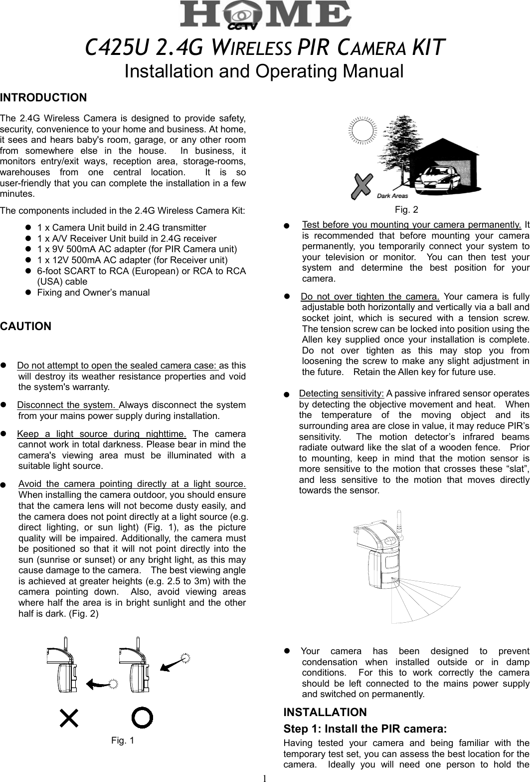
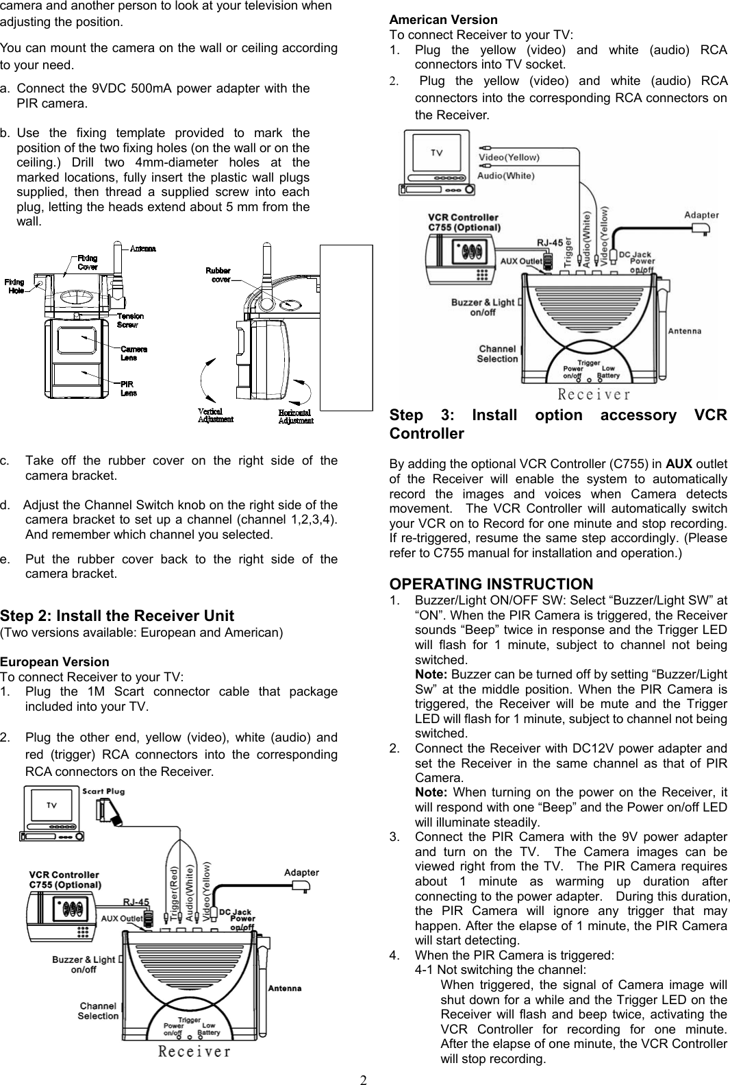
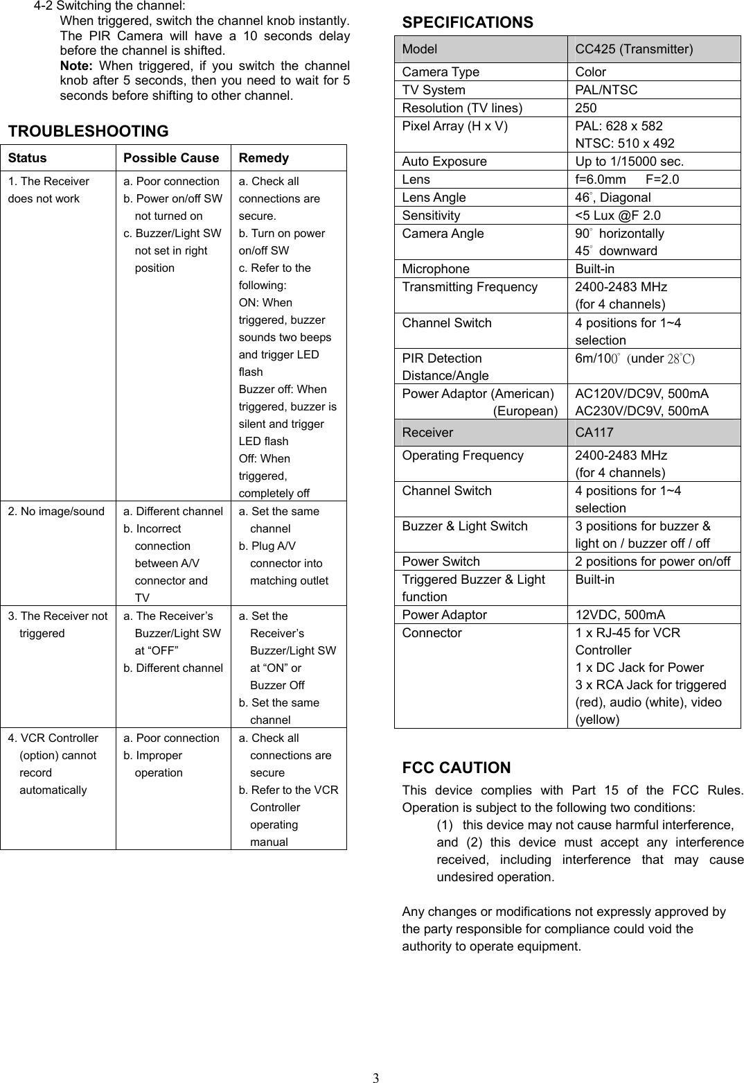
USERS MANUAL
Navigation menu
Upload a User Manual
Namespaces
Wiki Guide
HTML
PDF
Info
Views
User Manual
Discussion / Help
Navigation