Everspring Industry Co ED101 PIR Sensor Lantern Transmitter User Manual FU5ED101 Manual
Everspring Industry Co Ltd PIR Sensor Lantern Transmitter FU5ED101 Manual
Users Manual
ED101
PIR SENSOR LANTERN
TRANSMITTER
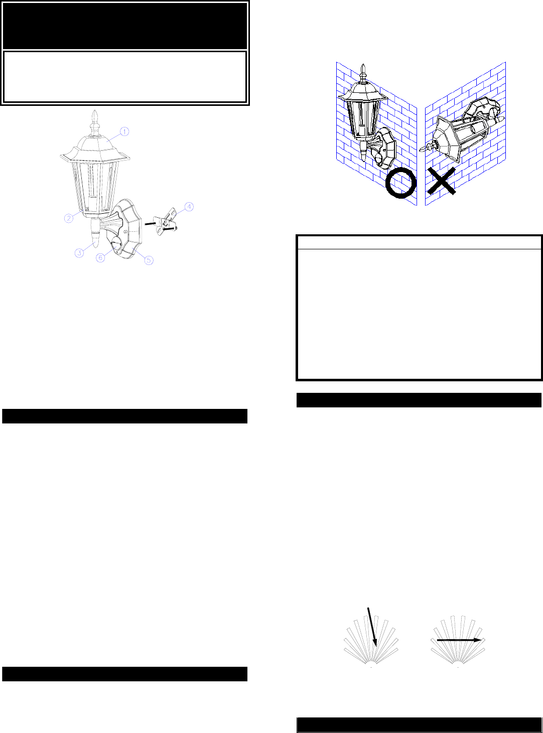
ED101
Top Cover
Glass
TX module
Mounting Bracket
Front Cover
⑥ PIR (Motion Sensor)
INTRODUCTION
Your EVERSPRING PIR SENSOR LANTERN
TRANSMITTER is a unique indoor or outdoor lighting
system for your home or business. At night, the built-in
passive infrared (PIR) motion sensor turns on the
LANTERN when it detects motion in its coverage area.
During the day, the built-in photocell sensor saves
electricity by deactivating the lantern.
This LANTERN TRANSMITTER is compatible with a
full series of our O-NET products, serving as a
transmitter. Upon motion being detected, it will
illuminate for the length of preset interval and send a
“Start” radio signal to the associated receiver (refer to
IMPORTANT) simultaneously. After expiry of preset
interval, it will emit a “Stop” radio signal to the receiver
for execution.
Note: Read this entire manual before you start to
install the system.
SAFETY PRECAUTIONS
Do not install when it is raining.
Be sure to switch off power source before
installing.
Make sure that the power wiring comes from
circuit with an external 16A miniature circuit
breaker for the short circuit protection or a suitable
fuse.
Keep minimum 0.5m away from the lighted
objects.
The unit can be installed only vertically (FIGURE
1a), not horizontally (FIGURE 1b) as shown in the
below drawing.
VERTICAL HORIZONTAL
FIGURE 1a & 1b
IMPORTANT
Some local building codes may require installation of
this product by a qualified electrician.
Check your local codes as they apply to your
situation. If the house wiring is of aluminum, consult
with an electrician about proper wiring methods.
Before proceeding with the installation, TURN OFF
THE POWER TO THE LIGHTING CIRCUIT AT THE
CIRCUIT BREAKER OR FUSE BOX TO AVOID
ELECTRICAL SHOCK.
CHOOSING A MOUNTING LOCATION
For the best results, fix your lantern on a solid
surface, 1.8~2.4m above the ground.
For outdoor installation, a location under eaves is
preferable.
Avoid aiming the motion sensor at pools, heating
vents, air conditioners or objects which may
change temperature rapidly.
Do not allow sunlight to fall directly on the front of
unit.
Try to avoid pointing the unit at trees or shrubs or
where the motion of pets may be detected.
Prior to mounting, keep in mind that the motion
sensor is most sensitive to the motion, which is
across the detection field and less sensitive to the
motion, which moves directly towards the detector
(FIGURE 2).
SENSOR SENSOR
LESS SENSITIVE MORE SENSITIVE
FIGURE 2
LANTERN ASSEMBLY
(1) Fit the lantern compartment onto the base.
(FIGURE 3)
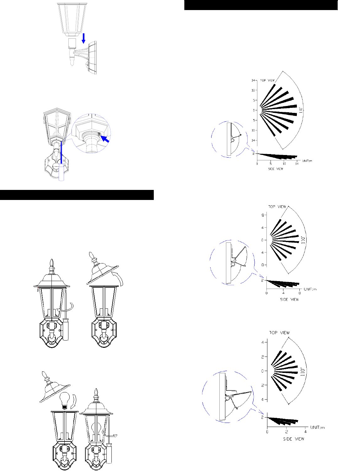
1
FIGURE 3
(2) Secure the lantern compartment with the two
screws provided. (FIGURE 4)
FIGURE 4
BULB INSTALLATION
(1) Do not touch the bulb while it is in use or still hot.
Allow it to cool off (about 5 minutes) before
touching it.
(2) Do not use the bulb rated higher than 100 watts.
(3) Switch off the power source. Unscrew retaining
screw from the top cover (FIGURE 5).
FIGURE 5
(4) Replace the new bulb and screw back the top
cover (FIGURE 6).
FIGURE 6
2
INSTALLATION
To facilitate installation, it is essential to get a drill and
a screwdriver ready. Select a location for the unit
based on the coverage angles shown in FIGURE 7a,
7b, 7c.
For farther detection area, hinge the PIR cover
upward (the first shift).
FIGURE 7a
For far detection area, hinge the PIR cover to the
second shift.
FIGURE 7b
For near detection area, hinge the PIR cover to
the third shift.
FIGURE 7c
Install a wall switch adjacent to the power source
(FIGURE 8). This helps you operate the lantern with
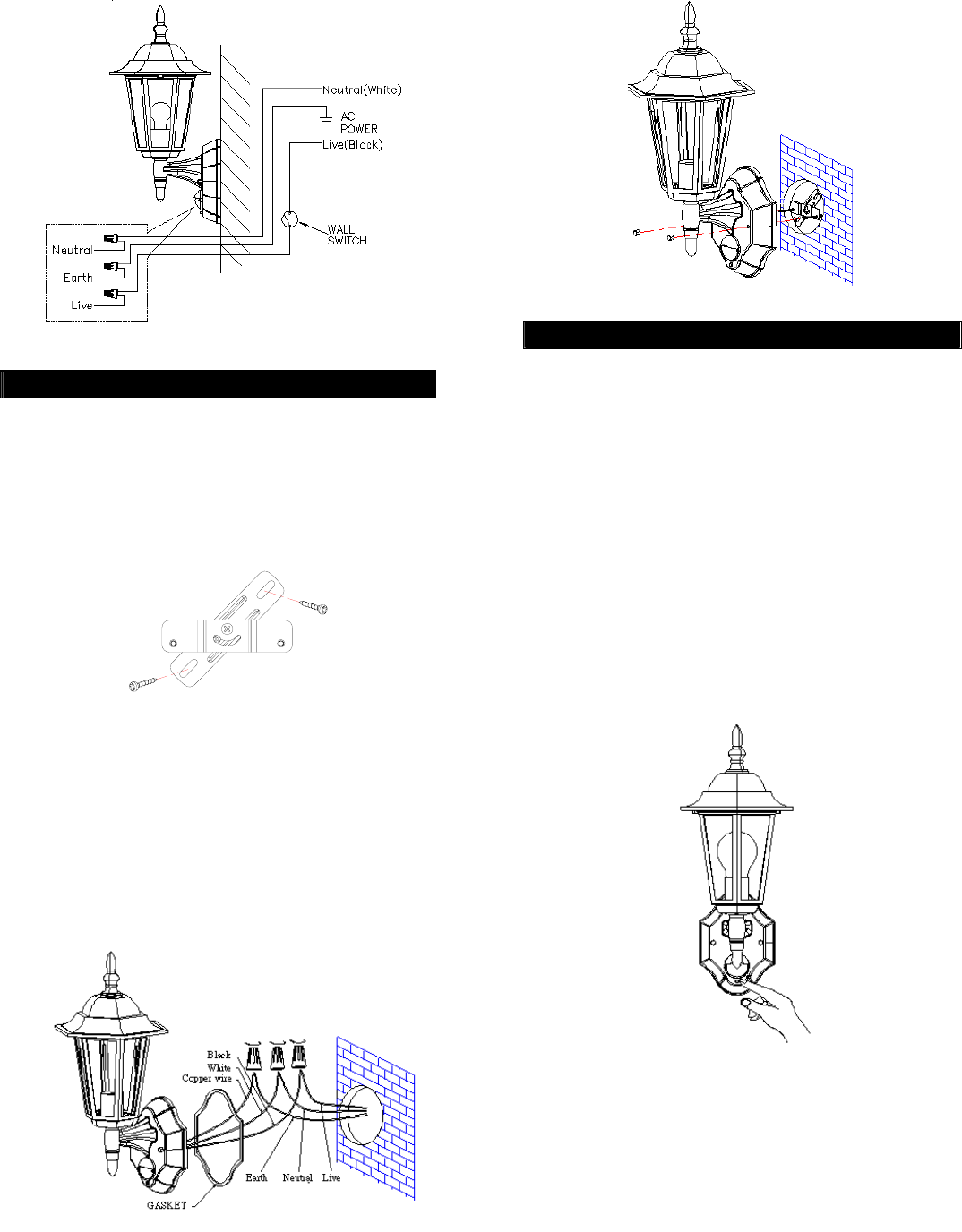
ease. See OPERATION for further information.
3
FIGURE 8
WIRING INSTRUCTION
(1) Switch off the power source.
(2) Line up the holes on the mounting bracket with the
holes on your junction box. Using fitting screws
(depending on size of the holes in your junction
box), attach the mounting bracket to your junction
box. (FIGURE 9).
FIGURE 9
(3) Place the gasket in position before wiring.
(4) Connect the black wire from the fixture to the
black (Live) power supply wire from your power
source using the wire nuts provided. Connect the
white wire from the fixture to the white (Neutral)
power supply wire using the wire nuts provided.
Connect the copper colored ground wire from the
fixture to house ground wire using the wire nuts
provided. (FIGURE 10)
FIGURE 10
(5) Place the front cover and secure it with the two
screws provided (FIGURE 11).
4
FIGURE 11
SETTING THE LIGHTING SYSTEM
(1) CODE LEARNING
Note: Prior to going ahead with code learning
procedure, ensure that the associated receiver has
entered code learning mode. For more details, please
refer to receiver’s operating manual. Any number of TX
lanterns can be used with the associated receivers,
providing they have implemented code learning
process within effective radio range (min. 70 meters).
a. Upon completion of wiring installation as
mentioned above, start “code learning” setting.
b. Pressing LED button at least 3 seconds will emit
“learning command” radio signal to the associated
receiver.(FIGURE 12) During 3 seconds
transmission period, the LED button will illuminate
for about 1.5 seconds.
FIGURE 12
c. Confirm if the associated receiver had learned the
code successfully.
d. If code learning is successful, start operating the
lantern.
e. If not, check if the code learning duration for the
associated receiver is overdue. If code learning
duration does not expire, resume “b” step as
mentioned above.
f. If code learning duration for the associated
receiver is overdue, it implies that code learning
is failure. Start from “a” step and afterward for retry.
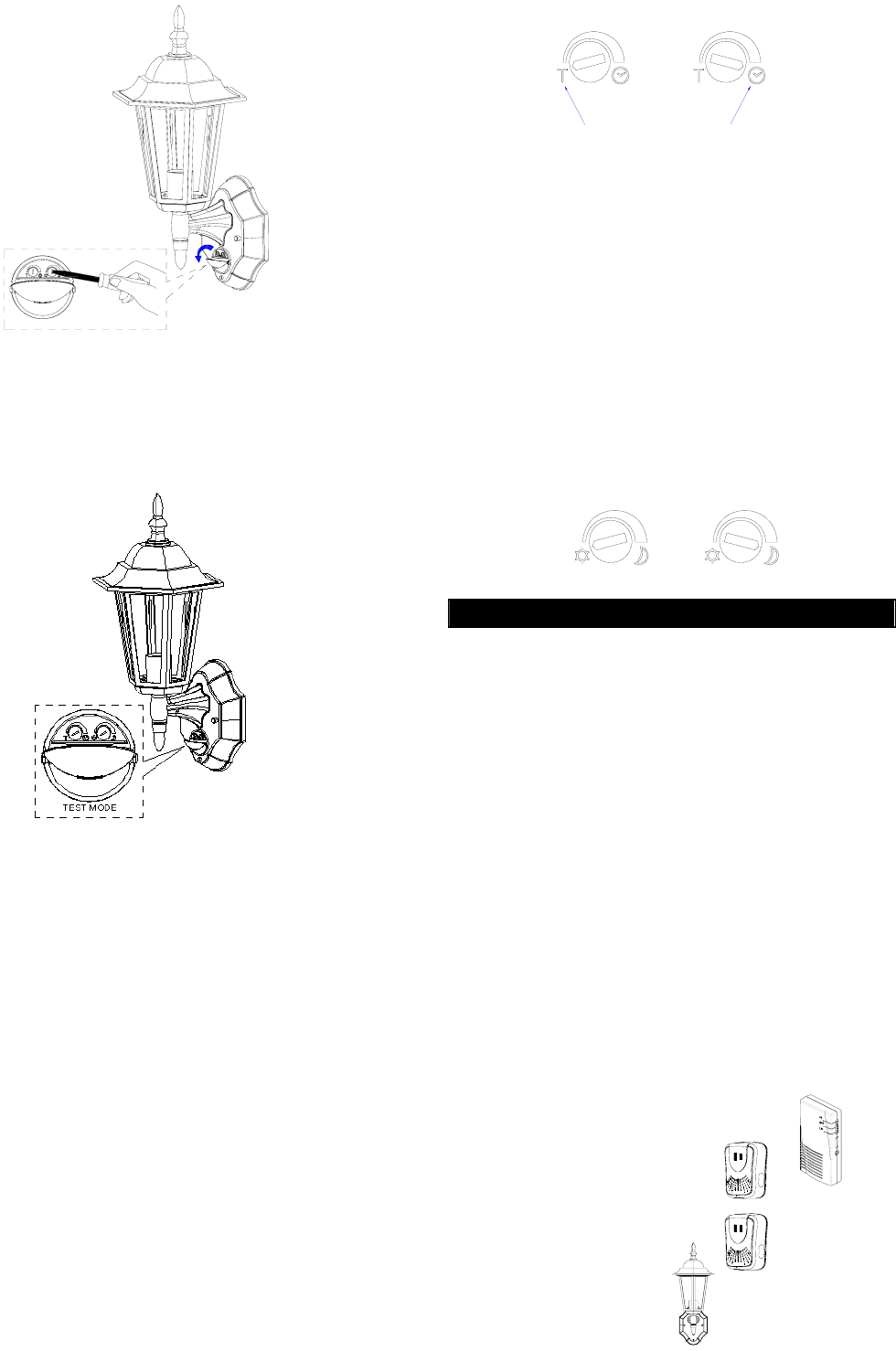
Prior to adjusting the PIR, hinge the PIR cover
downward. (FIGURE 13)
5
FIGURE 13
(2) TEST MODE
Turn the LUX control and the TIME control anti-
clockwise to the edge – the TEST position.
(FIGURE 14)
FIGURE 14
Turn on the wall switch. The lantern will turn on
for about 1 minute to warm up. Then it turns off.
Walk through the detection area. The lantern
turns on when you move and turns off after 5
seconds. Wait for the lantern to turn off before
moving again to test the sensor.
Adjust the motion sensor to cover the desired
detection area. See Installation for details.
(3) TIME ADJUSTMENT
Default setting: 5 seconds
The interval between “Start” and “Stop” radio signal
can be adjusted. After motion is detected, it will start
counting and emitting a “Start” radio signal. After expiry
of preset interval, a “Stop” radio signal will be sent to
the associated receiver for execution. If another motion
has been detected before the preset interval expires, it
will resume counting and emitting a “Start” radio signal
again.
Turn the TIME control knob clockwise to increase (up
to about 12 minutes) how long the interval will be or
anti-clockwise to decrease (down to about 5 seconds)
the interval (FIGURE 15).
6
ABOUT 5 SECONDS ABOUT 12 MINUTES
FIGURE 15
(4) LUX ADJUSTMENT
Default setting: 1,000 Lux
The LUX adjustment determines at what light level the
lighting system will start operating when you set the
sensor to automatic operation.
Provisionally turn the Motion Sensor LUX control knob
to the edge counter-clockwise at the moon (dusk)
position (FIGURE 16). In this provisional setting mode,
the Motion Sensor remains inactive during daylight. At
dusk when you find it is the LUX level desired for
operation, simply set the LUX control knob to the
position which will become active as daylight declines.
FIGURE 16
OPERATION
By using the connected wall switch, you can easily
operate the lantern.
(1) AUTOMATIC OPERATION
Turn on the wall switch. The lantern will be on when
the sensor detects motion and will be off after expiry of
preset interval. The built-in photocell turns the sensor
off and on according to the light level selected by the
LUX adjustment.
(2) MANUAL OVERRIDE
In Manual Override mode, the lantern will remain on for
around 4 ~ 6 hours and will be off automatically.
Pressing LED button will enter the manual override
mode, while pressing LED button again will be set back
to automatic operation mode.
IMPORTANT: This lantern transmitter is compatible
with the following receivers of O-NET series:
Portable RF 2-tone Sounder (SE101)
On/Off Receiver (B410N)
Dimmer Receiver (B410D)
RX Lantern (ED102)

7
EZ Alarm (SE131)
The member of O-NET series is on the increase. Visit
our website www.everspring.com for update
information.
TROUBLE SHOOTING
Cannot proceed code learning setting:
Check if wall switch is turned on.
Make sure the wiring connection is correct.
Light does not turn on:
Confirm that you have made a correct “wiring
connection”.
Make sure that the bulb has not burned out.
PIR detection not working
Check if wall switch is turned on.
Make sure that the PIR cover does not block
the PIR detection coverage.
Ensure that PIR detector is not mounted above
a radiator or heater or relocate the PIR detector.
Others:
Consult with your local service agent or a
qualified electrician.
SPECIFICATIONS
Power Requirement AC 120V / 60Hz
Lighting Load Max. 100W Incandescent
Frequency 315MHz
Transmission Range Min. 70m (in open space)
Detection Angle Up to 110° at 25° C
Detection Distance Up to 14m (45.9ft) at 25° C
Mounting Height Recommended 1.8-2.4m
(5.9-7.8ft) Wall Mount
Wall Switch Control On /Off
LED Button Code learning & manual
override setting
Time Adjustment 5sec. - 12 min.
Lux Adjustment 5-1000 lux
Warm Up Time About 1 min.
Protection Class I
Protection Degree IP44
Safety UL, cUL
Specifications subject to change without notice.
INED101EVSP0E2A
Federal Communication Commission
Interference Statement
This equipment has been tested and found to comply
with the limits for a Class B digital device, pursuant to
Part 15 of the FCC Rules. These limits are designed
5
to provide reasonable protection against harmful
interference in a residential installation. This
equipment generates, uses and can radiate radio
frequency energy and, if not installed and used in
accordance with the instructions, may cause harmful
interference to radio communications. However, there
is no guarantee that interference will not occur in a
particular installation. If this equipment does cause
harmful interference to radio or television reception,
which can be determined by turning the equipment off
and on, the user is encouraged to try to correct the
interference by one of the following measures:
- Reorient or relocate the receiving antenna.
- Increase the separation between the equipment
and receiver.
- Connect the equipment into an outlet on a circuit
different from that to which the receiver is
connected.
- Consult the dealer or an experienced radio/TV
technician for help.
This device complies with Part 15 of the FCC Rules.
Operation is subject to the following two conditions: (1)
This device may not cause harmful interference, and (2)
this device must accept any interference received,
including interference that may cause undesired
operation.
FCC Caution: Any changes or modifications not
expressly approved by the party responsible for
compliance could void the user's authority to operate
this equipment.
IMPORTANT NOTE:
FCC Radiation Exposure Statement:
This equipment complies with FCC radiation exposure
limits set forth for an uncontrolled environment. End
users must follow the specific operating instructions for
satisfying RF exposure compliance.
This transmitter must not be co-located or operating in
conjunction with any other antenna or transmitter.