Everspring Industry Co H302P Wireless Alarm System, PIR Detector User Manual H302W
Everspring Industry Co Ltd Wireless Alarm System, PIR Detector H302W
UserManual.wiki
>
Everspring Industry Co
>
H302P User Manual
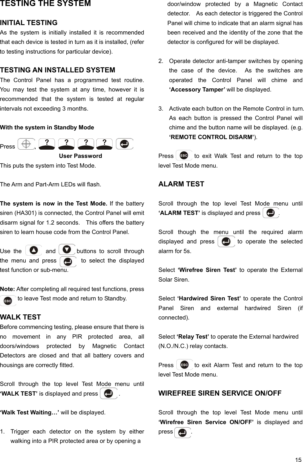
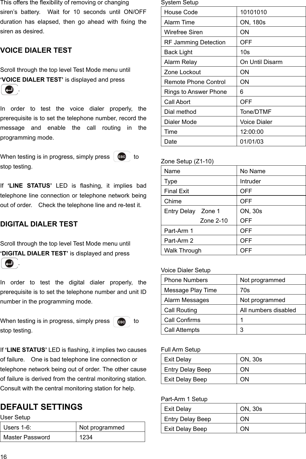
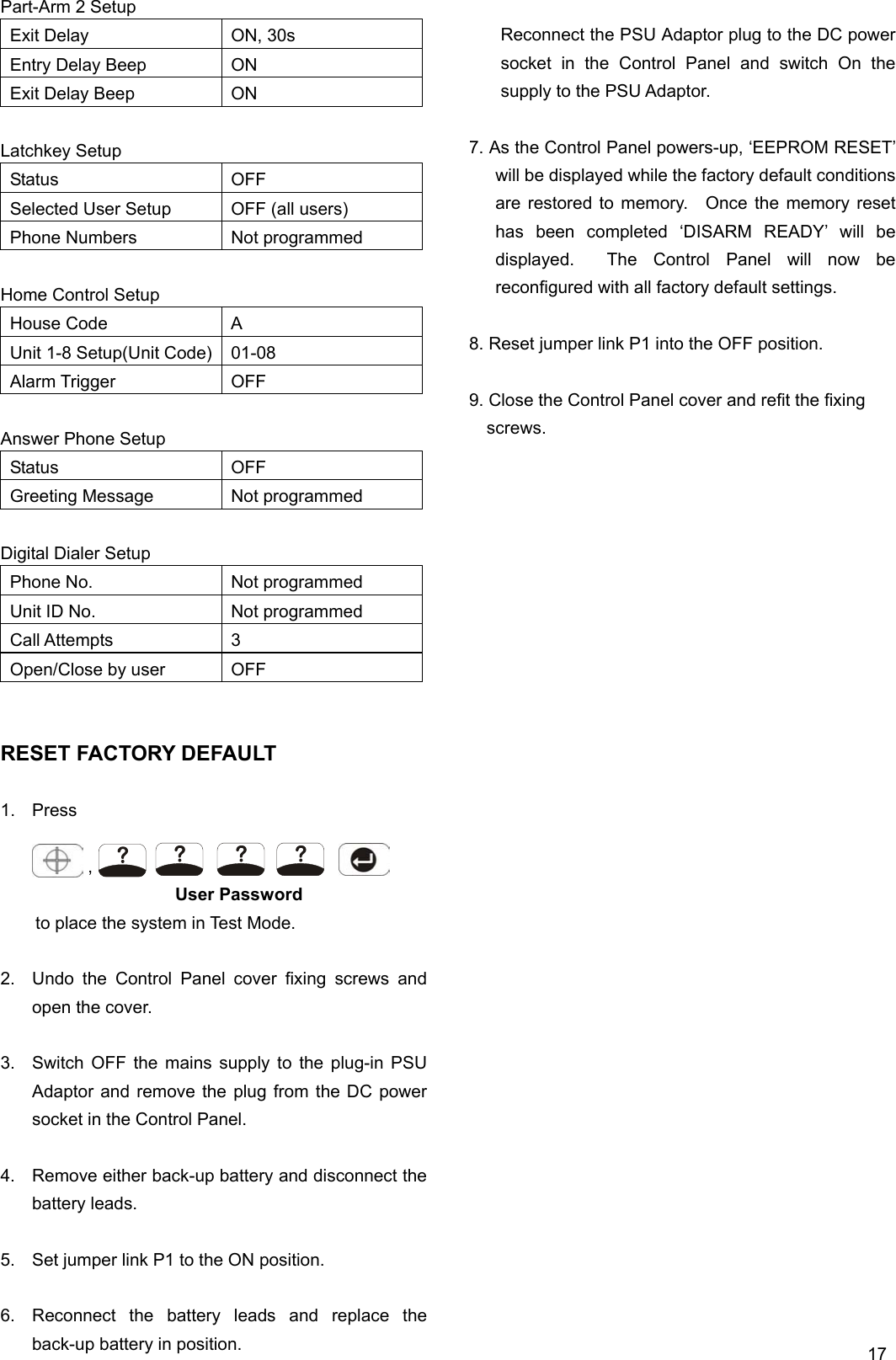
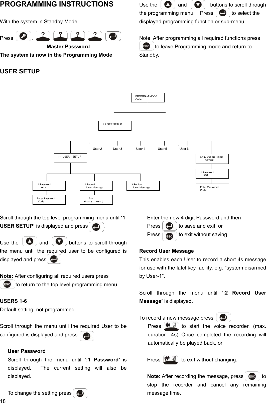
User Manual
Navigation menu
Upload a User Manual
Namespaces
Wiki Guide
HTML
PDF
Info
Views
User Manual
Discussion / Help
Navigation