Everspring Industry Co H302Q Wireless Alarm System, Control Panel User Manual H302W
Everspring Industry Co Ltd Wireless Alarm System, Control Panel H302W
User Manual
H302W
10-Zone Wirefree Alarm System
Installation & Operating
Manual
Copyright ©2003 All Right Reserved.
CONTENTS
KIT CONTENTS 1
INTRODUCTION AND OVERVIEW 2
Multiple Users 2
System Arming 2
Zones 2
Entry/Exit Delay 2
Quick Set 2
Final Exit Set Zone 2
Walk Through Zone 2
Omit Zone 3
Zone Lockout 3
Event Log 3
Chime 3
Voice Dialer 3
Digital Dialer 3
Latch-Key 3
Answer-Phone 3
Voice Memo 3
Remote System Control 3
Tamper Protection 4
Jamming Detection 4
Battery Monitoring 4
System House Code 4
PLANNING AND EXTENDING YOUR
WIREFREE ALARM SYSTEM 5
REMOTE CONTROL UNIT 6
General Information 6
Setting the Remote Control 6
CONTROL PANEL 6
Locating the Control Panel 6
Mounting the Control Panel 7
Setting the Control Panel 8
Testing the Control Panel & Remote Control 8
PASSIVE INFRA-RED DETECTORS 9
Choosing a Mounting Location 9
Installing the PIR Detectors 10
Setting the PIR Detectors 10
Testing the PIR Detectors 11
MAGNETIC CONTACT DETECTORS 11
Choosing a Mounting Location 12
Installing the Magnetic Contact Detectors 12
Setting the Magnetic Contact Detectors 13
Testing the Magnetic Contact Detectors 13
EXTERNAL CONNECTIONS 14
TESTING THE SYSTEM 15
Initial Testing 15
Testing an Installed System 15
DEFAULT SETTINGS 16
Reset Factory Default 17
PROGRAMMING 18
User Setup 18
System Setup 20
Zone Setup 23
Voice Dialer Setup 25
Arm Status Setup 28
Part-Arm 1 Setup 29
Part-Arm 2 Setup 29
Latch Key Setup 30
Home Control Setup 31
Answer Phone Setup 33
Digital Dialer Setup 33
OPERATION INSTRUCTIONS 36
Operating Instructions 36
Arm 36
Part-Arm 1 36
Part-Arm 2 36
Disarm 36
Quick Set 37
Omit Zone 37
Panic Alarm 37
Tamper 37
Chime 37
Event-Log 37
Voice Memo 38
Replay Messages 38
Remote System Control 38
Connection to Home Automation Modules 39
Battery Monitoring 39
MAINTENANCE 40
ALARM RECORD 41
TROUBLESHOOTING 42
DIGITAL DIALER TRANSMISSION 43
PROTOCOL
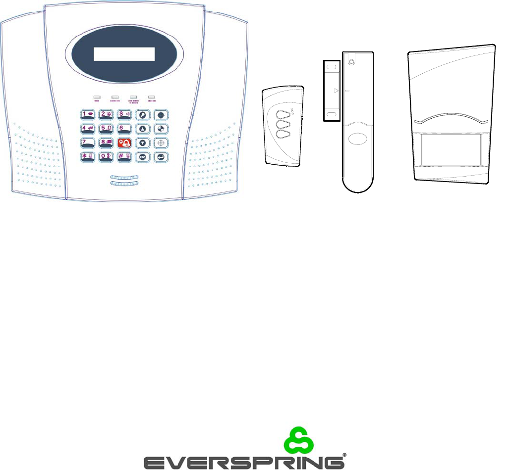
KIT CONTENTS
The Alarm System should contain the following
components.
1 x LCD Control Panel
1 x PIR Detector
1 x Magnetic Contact Detector
1 x Remote Control
Also included:
Power Supply Adaptor
Telephone Connection Lead
Installation & Operating Manual
Fixing pack
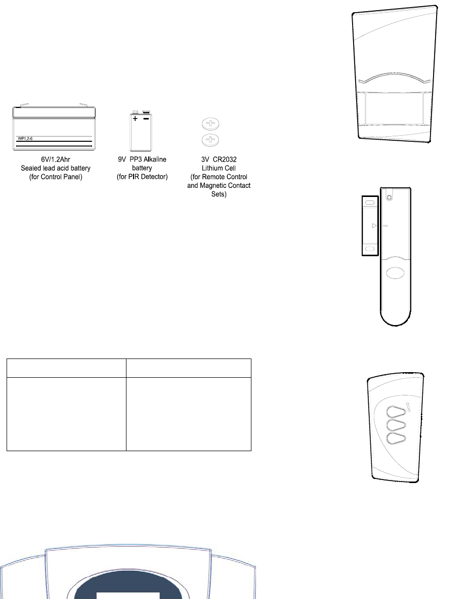
Batteries
2 x 6V/1.2Ahr Sealed lead acid battery
1 x 9V PP3 Alkaline battery
3 x 3V CR2032 Lithium
IMPORTANT
Please check all items as mentioned above are
included in the package.
COMMON ACCESSORIES FOR CONTROL
PANELS
The following accessories are compatible with a series
of Everspring’s alarm systems as below:
Control Unit Compatible Accessories
H302W, H302Y, HA65U H302P PIR Detector
H302R Remote Control
H202M Magnetic Contact
Detector
H302Q LCD Control Panel
H302P PIR Detector
H202M Magnetic Contact Detector
H302R Remote Control
INTRODUCTION AND OVERVIEW
MULTIPLE USERS
The system allows for up to 6 Users and a Master User
to be configured. This allows the system Event Log to
maintain a record of which users have armed and
disarmed the system. Each user will have a different
Password. In addition a 4 second voice recorder
facility enables the users name to be recorded for use
with the Latch-Key facility.
Only the Master User has access to the programming
functions and is able to configure the system.
Note: Any Remote Control Units on the system will be
recorded as User 6.
SYSTEM ARMING
The system has a full ‘Arm’ and two ‘Part-Arm’ modes.
ARM will ‘Arm’ all zones while the ‘Part-Arm’ modes will
only arm the zones that are enabled for the particular
part-arm mode.
For example:
The system could be configured such that during night
time, ‘Part-Arm 1’ would arm only zones protecting the
lower floor and outbuildings leaving the upper floor free
for movement without triggering the alarm.
During the day while the property is occupied ‘Part-Arm
2’ would arm only the zones protecting the outbuildings.
However, when the property is left un-occupied, the full
‘Arm’ mode will arm all zones to protect the entire
property, (i.e. upper and lower floors and outbuildings).
ZONES
The system incorporates 6 wireless Alarm Zones for
the connection of the system detectors that are used to
independently monitor different areas of the property.
In addition to standard intruder protection, each zone
may also be configured to operate in one of four other
modes:
- ‘PANIC/PA’ mode provides 24 hour monitoring of
any Personal Attack (PA) switches incorporated
into the system.
- ‘24-hour Intruder’ mode provides 24 hour intruder
protection for areas/zones where continuous
monitoring is required, (e.g. gun lockers).
- ‘Fire’ mode provides 24 hour monitoring of any
Fire/Smoke detectors incorporated into the system.
- ‘Test’ mode allows a zone to be monitored while the
2
system is armed. If a detector on a test zone is
triggered an entry will be recorded in the Event
Log but an alarm will not occur.
In addition there is the facility to connect 4 hard wired
zones to the Control Panel, each of which is fully
configurable with the same features as the wirefree
zones (1-6).
ENTRY/EXIT DELAY
When the system is armed with the Exit-Delay enabled,
no alarm signal from any detector on an active zone will
be able to initiate an alarm until the Exit-Delay has
expired. This enables the system to be armed from
within the property and allows time for the user to exit
the property without triggering an alarm. If the
Exit-Delay is disabled then detectors on active zones
will immediately be able to initiate an alarm as soon as
the system begins to arm.
The system Exit-Delay may be configured for between
10 to 250 seconds or disabled completely.
If a detector on a zone with its Entry-Delay enabled is
triggered, then an alarm condition will not occur until
the Entry-Delay period has expired. This allows time
for the user to re-enter the property and disarm the
system before an alarm condition occurs. Generally
only the zones on the main entry route to the property
will be configured with an Entry-Delay. The remaining
zones would be configured with their Entry-Delay
disabled allowing them to immediately initiate an alarm
a detector on the zone is triggered.
The Entry-Delay for each zone may be configured for
between 10 to 250 seconds or disabled completely.
QUICK SET
The system may be fully armed in 5 seconds using the
quick set facility, overriding the programmed exit-delay.
This is useful for setting the system at night when the
exit-delay warning beep will be silenced after just a few
seconds.
FINAL EXIT SET ZONE
Triggering a detector on a Final Exit zone during the
exit-delay will cause the delay to reset to 5 seconds
with the system arming 5 seconds later.
WALK THROUGH ZONE
This feature may be used for detectors located on the
main entry route to the Control Panel. When the
system is armed and a zone configured as a ‘Master
Walk Through’ zone is triggered, the zones Entry-Delay
will start. Any zones configured as ‘Slave Walk
Through’ will be disabled to allow free access to the

Control Panel to disarm the system before the
entry-delay expires an alarm occurs.
If access is gained via a zone that is not configured as
‘Master Walk Through’, the ‘Slave Walk Through’ zones
will operate as normal according to their programmed
Entry-Delay setting.
Note: A zone set as a ‘Master Walk Through’ zone
must be configured with an Entry-Delay.
OMIT ZONE
A zone may be temporarily omitted when the system is
armed using the Omit feature. When the system is next
disarmed any zones set to Omit will be cancelled.
ZONE LOCKOUT
If a detector on an active zone is triggered while the
system is armed an alarm condition will occur. After
the programmed alarm duration has expired the alarm
will stop and the system will automatically reset.
Subsequent detectors triggered will again initiate an
alarm condition. If a single zone initiates an alarm
condition more than three times then that zone will be
‘Locked Out’ and any further alarm signals from that
zone will be ignored until the system is disarmed.
Note: The ‘Zone Lockout’ feature can be disabled if
required.
EVENT LOG
The Control Panel incorporates a memory capable of
storing the last 50 system events. This enables the
user to see which user has Armed/Disarmed the
system and if and when any alarms occurred. The
time, date and details of the event type will be recorded
for each system event.
CHIME
Chime is a low security facility for use when the system
is Standby mode. If the Chime feature is ON, and a
detector on a zone that has its Chime function enabled
is triggered, the internal sounder will produce a low
volume warning tone. A typical use of the Chime
function would be to warn that a door or particular area
has been accessed.
VOICE DIALER
If the Voice Dialer is enabled and an alarm condition
occurs, the system will call for help using your recorded
alarm messages and up to four telephone numbers.
When an alarm condition occurs, the telephone voice
dialer (if enabled) will call the first enabled number in
the calling sequence and replay the recorded alarm
messages for the configured ‘Play Time’. The recipient
must acknowledge the message by pressing the
button on their telephone keypad. If the call is
unanswered or an acknowledgment is not received
then the next active number in the dialing sequence will
be called. The dialer will continue calling each
number in turn until either all numbers in the sequence
have been dialed the set number of times or the
sequence is cancelled/acknowledged by the recipient.
DIGITAL DIALER
As an alternative to the Voice dialer the system may be
configured to interface with a central monitoring station.
LATCH KEY
When the system is disarmed the Latch-Key facility, if
enabled, will call the first latchkey phone number and
replay the user message (recorded under user setup)
for the set ‘Play Time’. The recipient must
acknowledge the message by pressing the
button on the telephone keypad. If the call is
unanswered or an acknowledgment is not received
then the second latchkey phone number will be called.
The voice dialer will continue calling each number in
turn until each number has been dialed the set number
of times or the sequence is cancelled/acknowledged by
the recipient.
For example, the latchkey facility is useful to inform
parents that a child has returned from school and
disarmed the system.
ANSWER PHONE
The Control Panel includes an answer-phone facility.
The answer phone will record and store a maximum of
6 messages with each message being limited to a 30s
duration.
Messages may be retrieved either direct from the
Control Panel or by dialing into the system from a
phone.
VOICE MEMO
In addition it is also possible to record messages at the
Control Panel using the ‘Voice-Memo’ facility. Each
voice-memo message is limited to a maximum duration
of 30s and counts as an answer phone message.
REMOTE SYSTEM CONTROL
It is possible to dial into the system via the connected
telephone line to interrogate the system status and to
have basic control over the system, (e.g. to Arm and
Disarm the system). You may also activate the
microphone on the control panel to Listen-In to what is
3
happening in the protected property.
Answer phone and Voice-memo messages may also
be accessed remotely.
TAMPER PROTECTION
All system devices (except the Remote Control Units)
incorporate Tamper protection features to protect
against unauthorized attempts to interfere with the
device. Any attempt to remove the battery covers from
any device (except the Remote Control) or to remove
the Solar Siren or Control Panel from the wall will
initiate an alarm condition (unless the system is in Test
or Programming modes), even if the system is
Disarmed.
JAMMING DETECTION
In order to detect any attempts to illegally jam the radio
channel used by your alarm system, a special jamming
detection function is incorporated into the Control Panel
and Solar Siren. If this feature is enabled, and the
radio channel is jammed continuously for 30 seconds,
when the system is armed, the Solar Siren will emit a
pre-alarm series of rapid bleeps for 5 seconds. If the
jamming continues for a further 10 seconds or more a
full alarm condition will occur. In addition if the system
is jammed for more than three periods of 10 seconds in
a 5 minute interval, this will also generate a Full Alarm
condition.
The jamming detection features in the Control Panel
and Solar Siren operate independently.
The Jamming Detection circuit is designed to
permanently scan for jamming signals. However, it is
possible that it may detect other local radio interference
operating legally or illegally on the same frequency. If
it is planned to operate the jamming detection feature
we recommend that the system is monitored for false
jamming alarms for at least 2 weeks prior to leaving the
Jamming Detection function permanently enabled.
BATTERY MONITORING
In addition to the battery monitor and low-battery
indicators in each device, the Control Panel will also
indicate a low battery status within any Passive
Infra-Red or Magnetic Contact Detector on the system
using the Event log.
SYSTEM HOUSE CODE
In order to prevent any unauthorized attempt to operate
or disarm your system, you must configure your system
to accept radio signals only from your own system
devices. This is done by setting a series of eight
4
miniature (DIP) switches in all devices (except the
Control Panel) to the same ON/OFF combination (the
House Code) selected by the user/installer. The
Control Panel is then programmed to operate only with
devices set to this House Code. All detectors and
Remote Control Unit(s) must be configured with the
same House Code in order for the system to operate
correctly.
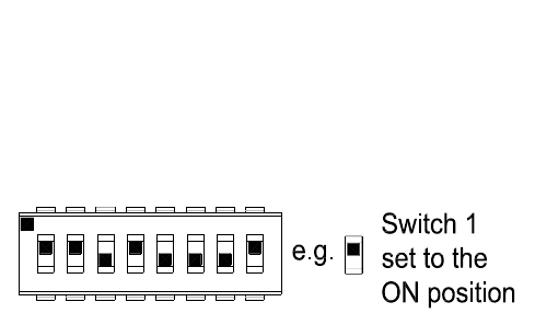
Inside the Siren, Detectors and Remote Control Unit is
a series of 8 DIP switches.
The House Code is set up by moving each of the 8
switches in each device to the same randomly selected
ON/OFF sequence. When setting the DIP switches,
ensure that each switch ‘clicks’ fully into position. Use
the tip of a ballpoint pen or a small screwdriver to move
each switch in turn.
Note: it is recommended that the system House Code
is always reset to a code other than the factory default.
PLANNING AND EXTENDING YOUR
5
1 32 4
ON
7
6 8
ECE
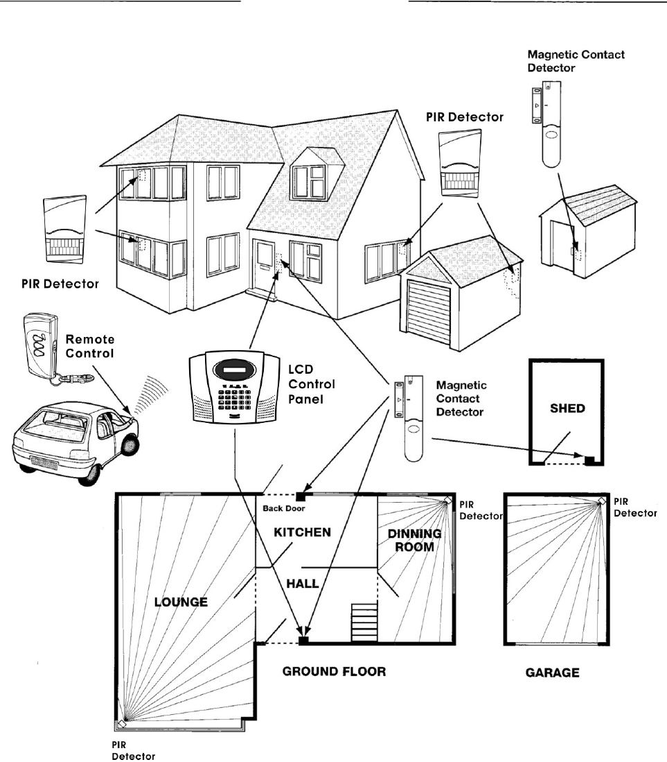
WIREFREE ALARM SYSTEM
The following example below shows a typical property
incorporating the suggested positions for the Control
Panel, PIR and Magnetic Detectors for optimum
security. Use this as a guide for your installation in
conjunction with the recommendations contained in this
manual for planning your intruder alarm system.
Before attempting to install your Alarm System it is
important to study your security requirements and plan
your installation.
The alarm system may be extended to provide even
greater protection by fitting additional PIR Detectors
and Magnetic Contact Detectors as required.
5
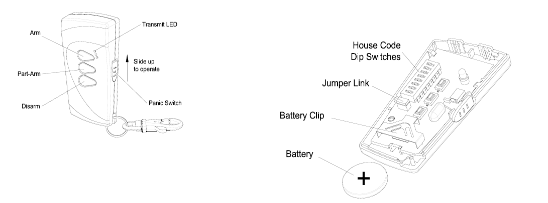
REMOTE CONTROL UNIT
The Remote Control Unit is used to Arm, Part-Arm and
Disarm the system.
The Remote Control Unit also incorporates a Panic
switch. Activating the Panic switch on the side of the
Remote Control will immediately initiate a Full Alarm
condition whether the system is Armed or Disarmed.
The alarm can be cancelled by pressing the ‘DISARM’
button on the Remote Control or via the Control Panel.
Any number of Remote Control Units can be used with
your system, providing they are all coded with the
same system House Code.
The Remote Control adopts a CR2032 type Lithium cell
which under normal conditions will have typical life in
excess of 1 year. Under normal battery conditions the
LED on the Remote control will only illuminate when a
button is pressed. However, under low-battery
conditions this LED will flash every time the button is
pressed. When this occurs the batteries should be
replaced as soon as possible.
SETTING THE REMOTE CONTROL
1. Remove the rear cover by undoing the small screw
on the rear of the Remote Control.
2. Located above the battery cover is a row of 8 DIP
switches. Select and record a random combination
of ‘ON’ and ‘OFF’ positions for the DIP switches.
This will be the system House Code that enables
all elements of your transmitters to communicate
with the Control Panel.
IMPORTANT: The House Code for your system
should be changed from the factory default setting.
3. Ensure that the jumper link located immediately
below the House Code DIP switches is fitted in
position for use with this alarm system.
6
4. Insert the battery under the clip ensuring that the
+v terminal faces upwards away from the PCB.
5. Replace the rear cover and fixing screw.
CONTROL PANEL
LOCATING THE CONTROL PANEL
When choosing a suitable location for the Control
Panel, the following points should be considered.
1. The Control Panel should be located in a position
out of sight of potential intruders and in a safe
location, but easily accessible for system
operation.
2. The Control Panel should be mounted on a sound
flat surface to ensure that the rear tamper switch
on the Control Panel is closed when the Panel is
mounted. The Control Panel should be mounted
at a convenient height of between 1.5 and 2m and
in a position where it will be seen each day.
Note: If small children are in the household, a
further consideration should be given to keeping
the units out of their reach.
3. It is recommended that the Control Panel should
be positioned such that the Exit/Entry tone (emitted
by the Control Panel) can be heard from outside
the property.
4. The Control Panel should be mounted within a
protected area so that any intruder cannot reach
the Control Panel without opening a protected door
or passing through an area protected by a PIR
detector when the system is armed.
5. The Control Panel must be located within reach of
a mains socket.
6. If the telephone based functionality is to be used
then the Control Panel will need connecting to a
convenient telephone point.
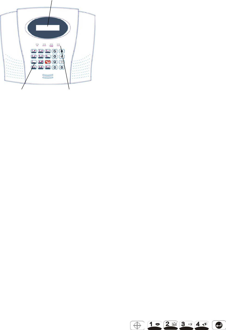
LCD Display Window
Keypad Status LEDs
LCD Control Panel – Keypad and LED Layout
Note: It is recommended that the telephone
connection lead is not extended beyond 5m before
connecting to a telephone master or secondary
outlet.
7. Do not locate the Control Unit closer than 1m to
any large metallic object, (e.g. mirrors, radiators,
etc) as this may affect the radio range of the
Control Panel.
MOUNTING THE CONTROL PANEL
1. Undo the two captive fixing screws on top of the
panel and open the cover. The cover is hinged
along the bottom edge.
2. Unclip and remove the two back-up batteries on
either side of the panel.
3. Hold the Control Panel in position on the wall and
mark the positions of the four fixing holes.
Remove the Panel and drill four 5mm holes and fit
the 25mm Wall Plugs.
IMPORTANT: Do not drill the fixing holes with the
Control Panel in position; as the resulting dust and
vibration may damage the Control Panel’s internal
components and invalidate the guarantee.
4. Fit two 18mm No.4 screws into the top holes until
almost fully home and hang the Control Panel over
these screws using the two keyhole slots in the top
corners of the panel casing.
5. Route the cable from the Power Supply Unit up
behind and on the right hand side of the Control
Panel and connect the plug to the DC power
socket in the panel. Ensuring that the cable is not
trapped between the panel and the wall.
6. Fix the Panel to the wall using two 18mm No. 4
screws in the lower two fixing holes in the panel
and tighten the upper fixing screws until they just
grip the casing. Do not over tighten the fixing
screws as this could damage or distort the casing.
7. Ensure that the ‘Reset’ and the ‘Hard-Wired
Siren tamper detect’ jumper links are set in the
OFF position.
8. Connect battery leads to both back-up batteries
and refit batteries.
Battery 1 (left): Red lead to +ve battery terminal
Blue lead to –ve battery terminal
Battery 2 (right): Blue lead to +ve battery terminal
Black lead to –ve battery terminal
IMPORTANT: Take care when connecting battery
leads to the batteries as connecting incorrectly
could damage the batteries or the Control Panel.
Note: The Power LED may flash to indicate that
the unit is being operated from the back-up
batteries and that mains supply is not present.
9. If fitted, remove the plastic film covering the LCD
display and on the display window on the cover.
10. Close the lid of the Control Panel and tighten the
captive fixing screws.
11. Plug in and switch ON the Power Supply Unit, (the
Power LED should illuminate).
12. If required, connect the Control Panel to the
telephone line using the cable supplied by inserting
small RJ11 plug into socket marked LINE located
on the bottom edge of the Control Panel.
If the cable supplied is not long enough to reach a
suitable phone point then it will need extending
using a coupler and extension lead (not supplied).
Note: If the Panel Tamper alarm sounds during the
installation reset the alarm by pressing:
, , ,
on the Control Panel Keypad.
7
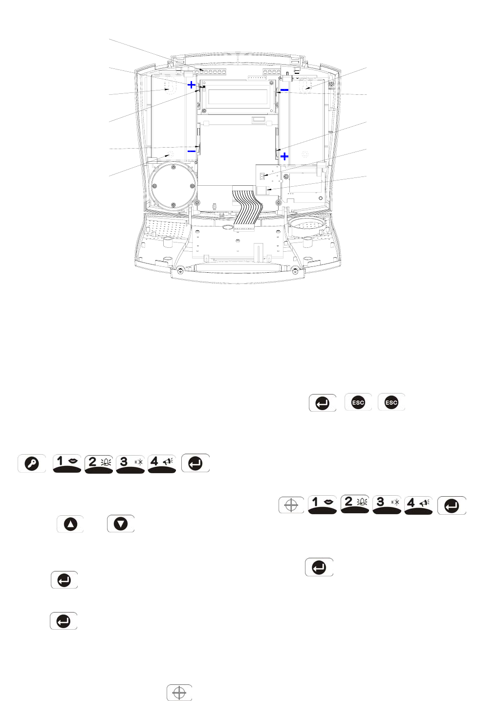
Inside View of Control Panel
SETTING THE CONTROL PANEL HOUSE
CODE
With unit in Standby mode (power LED only
illuminated).
1. Press
, ,
to put the system into Programming mode.
‘1. USER SETUP’ will be displayed.
2. Use the and buttons to scroll
through the menu until ‘2. SYSTEM SETUP’
is displayed.
Press and ‘2-1 Learn House Code’ will be
displayed.
Press again to set the Control Panel to
receive the House code. ‘DIP SW 12345678 & H
Code: xxxxxxxx’ will be displayed.
3. With the required House Code already configured
on the Remote Control, press the button on
the Remote Control.
When the Control Panel receives the signal from
the Remote Control the Display will change to
show the received house code on lower line of the
8
display beneath the corresponding DIP switch
numbers (1-8).
4. Press , , to return to
Standby mode.
TESTING THE CONTROL PANEL &
REMOTE CONTROL
1. Press
, ,
to put the system into Test mode.
‘TEST MODE – WALK TEST’ will be displayed.
2. Press to activate Walk Test.
‘ Walk Test Waiting…’ will be displayed.
3. Press the ‘ARM’ button on the Remote Control.
As the key is pressed the Control Panel will beep
and the type of the device and button will be
shown on the display.
Press the other buttons on the Remote Control in
turn, as each button is pressed the Control Panel
will beep and show the button being pressed on
the display.
4. Test the range of the Remote Control by pressing
the ‘DISARM’ button on the Remote Control from in
and around the property and from all locations
Upper Keyhole
Fixing Hole
-ve Terminal
(Black Lead)
(Blue Lead)
+ve Terminal
Link P1
Reset Jumper
Power Supply
Jack Socket
-ve Terminal
(Blue Lead)
(Red Lead)
+ve Terminal
External Tamper
Switch Jumper
Fixing Hole
Upper Keyhold
Lower Fixing
Hole
Link P51
Terminal Block
where you plan to install detectors. Check that
the Control Panel acknowledges the signal from
the
Remote Control each time the ‘DISARM’ button is
pressed.
5. Press to return to the top level menu of
TEST MODE.
PASSIVE INFRARED DETECTORS
PIR detectors are designed to detect movement in a
protected area by detecting changes in infra-red
radiation levels caused, for example, when a person
moves within or across the devices field of vision. If
movement is detected an alarm signal will be emitted,
(if the system and alarm zone is armed).
Note: PIR detectors will also detect animals, so ensure
that pets are not permitted access to areas fitted with
Passive Infra-Red Detectors when the system is
armed.
Any number of PIR Detectors can be used with your
system, providing they are all coded with the system
house code and are mounted within effective radio
range of the Control Panel.
The PIR Detector adopts a PP3 Alkaline battery which
under normal conditions will have typical life in excess
of 2 years. When the battery level drops, with the PIR
in normal mode and the battery cover fitted, the LED
behind the detection window will flash. When this
occurs the batteries should be replaced as soon as
possible.
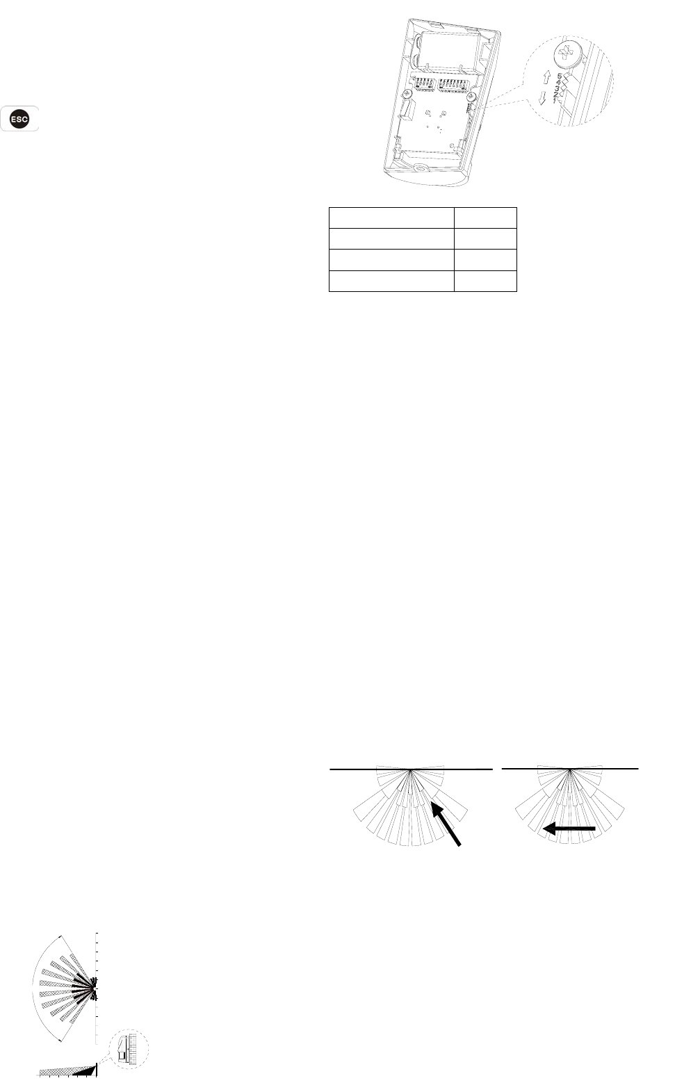
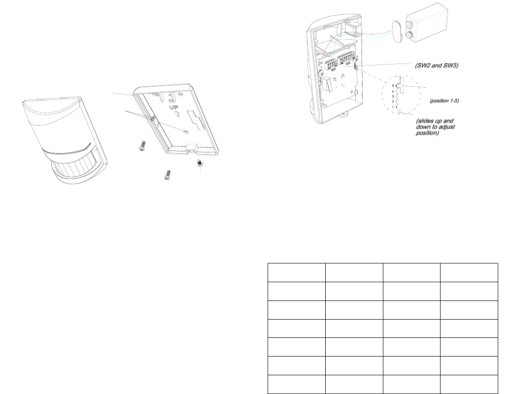
CHOOSING A MOUNTING LOCATION
The recommended position for a PIR Detector is in the
corner of a room mounted at a height between 2 and
2.5m. At this height, the detector will have a
maximum range of up to 12m with a field of view of 110
°. The position of the PCB inside the PIR can be set to
5 different positions to adjust the range of the detector.
Setting the PCB in position 3 will reduce the range to
9m approximately, with position 1 providing a range of
6m approximately. The recommended position
setting for the PCB is in position 5.
PCB Position Range
1 6m
3 9m
5 12m
Note: The range as indicated above refers to the
linear distance in front of the PIR sensor.
When considering and deciding upon the mounting
position for the detector the following points should be
considered to ensure trouble free operation:
1. Do not locate the detector facing a window or
where it is exposed to or facing direct sunlight.
PIR Detectors are not suitable for use in
conservatories.
2. Do not locate the detector where it is exposed to
ventilators.
3. Do not locate the detector directly above a heat
source, (e.g. fire, radiator, boiler, etc).
4. Where possible, mount the detector in the corner
of the room so that the logical path of an intruder
would cut across the fan detection pattern. PIR
detectors respond more effectively to movement
across the device than to movement directly
towards it.
Less Sensitive More Sensitive
5. Do not locate the detector in a position where it is
subject to excessive vibration.
6. Ensure that the position selected for the PIR
detector is within effective range of the Control
Panel, (refer to ‘Testing the Control Panel &
Remote Control’).
9
812 10 64 02
0
2
SIDE VIEW
TOP VIEW
110°
2
4
6
8
10
12
2
4
6
8
10
12
UNIT:M
Note: When the system is armed, household pets
should not be allowed into an area protected by a
PIR detector as their movement would trigger the
PIR and generate an alarm.
Note: DO NOT fix the detector to metalwork or
locate the unit within 1m of metalwork (i.e.
radiators, water pipes, etc) as this could affect the
radio range of the device.
INSTALLING THE PIR DETECTORS
Ensure that the system is in Test Mode.
1. Undo and remove the fixing screw from the bottom
edge of the PIR. Carefully pull the bottom edge of
the detector away from the rear cover and then
slide down to release the top clips.
2. Carefully drill out the required mounting holes in
the rear cover using a 3mm drill according to
whether the unit is being mounted in a corner or
against a flat wall.
3. Using the rear cover as a template, mark the
positions of the fixing holes on the wall.
4. Fix the rear cover to the wall using the two 18mm
No.4 screws and 25mm wall plugs, (a 5mm hole
will be required for the wall plugs). Do not
over-tighten the fixing screws as this may distort or
damage the cover.
5. Configure the PIR detector as described below.
Remember that on initial installation that the device
needs to be tested and should therefore be set in
Walk Test Mode.
6. Check that the detector PCB is located and set in
the correct position to give the detection zone
pattern required.
To adjust the PCB position, simply slide it up or
down ensuring that the location legs are aligned
with the required position number marked on the
board.
10
7. To refit the PIR detector to the rear cover, offer the
detector up to the rear cover and locate the clips in
the top edge into the rear cover. Push the lower
edge of the detector into place and refit the fixing
screw in the bottom edge of the PIR to secure in
position. Do not over-tighten the fixing screws as
this may damage the casing.
SETTING THE PIR DETECTORS
Located on the PCB of the PIR Detector are two blocks
of DIP switches (SW2 and SW3).
1. DIP switches SW2 (numbered 1-8) are used to set
the House Code for the PIR Detector and must be
set to the same ON/OFF combination as the House
Code DIP switches in all other system devices.
2. Set the alarm zone which the detector will operate
on with DIP switches 1-3 of SW3 as follows:
DIP 1 DIP 2 DIP 3
Zone 1 OFF OFF OFF
Zone 2 OFF OFF ON
Zone 3 OFF ON OFF
Zone 4 OFF ON ON
Zone 5 ON OFF OFF
Zone 6 ON OFF ON
3. DIP 4 of SW3 is used to configure the PIR Detector
for walk test mode, which allows the operation of
the detector to be checked during installation
without triggering a Full Alarm.
ON Walk Test mode
OFF Normal mode
Note: On initial installation the detector should be
set into Walk-Test mode ready for testing.
4. The PIR Detector incorporates an anti-false alarm
feature designed to compensate for situations
Rear Cover
Mounting Hole
Positions
Screw
Fixing
Indicator
PCB Position
PCB Board
Dip Switches

where the detector may be affected by
environmental changes, (e.g. insects, air
temperature, etc). This feature is called
“sensitivity detection” and may be selected for high
or low detection.
The recommended setting is for high sensitivity
detection. However, in cases of extreme
environmental problems or if unattributable false
alarms are experienced, it may be necessary to
select low sensitivity detection.
Set the required sensitivity detection using DIP 5 of
SW3 as follows:
ON high sensitivity detection
OFF low sensitivity detection
Note: The higher the sensitivity detection the less
movement will be necessary before the PIR
detector will trigger the alarm.
5. The setting of the DIP4 & DIP5 of SW3 can be
distinguished from the LED indication as follows:
Position
of DIP4
& 5 of
SW3
DIP4 of
SW3
DIP5 of
SW3
Trigger reaction of LED
High
Sensitivity
LED will be on shortly.
It implies high
sensitivity.
ON Walk Test
mode
Low
Sensitivity
LED will flash three
times and Illuminate
once. It implies low
sensitivity.
OFF Normal
mode
Low
Sensitivity
LED does not light up
6. Connect the PP3 Alkaline battery to the battery
clip.
Note: When the 9V Alkaline battery is connected,
the LED behind the lens will flash for 2-3 minutes
until the PIR has warmed-up and stabilized. The
LED will then stop flashing and turn OFF.
TESTING THE PIR DETECTORS
Ensure that the system is in Test Mode.
With the PIR detector set in Test mode and mounted in
position on the wall, allow 2-3 minutes for the detector
to stabilize before commencing the Walk Test.
1. Use the and buttons to scroll
through the menu until ‘WALK TEST’ is displayed.
Press to activate Walk Test.
‘ Walk Test Waiting…’ will be displayed.
2. Walk into and move slowly around the protected
area, each time the detector senses movement the
LED behind the lens will flash. In addition, the
Control Panel will beep to indicate that the alarm
signal has been received and the identity of the zone
that the detector is configured for will be displayed.
If necessary adjust the detection range by changing
the mounting position of the PCB within the PIR
housing.
Note: In normal operation, the LED behind the PIR
lens will not flash on movement detection, (unless
the battery is low).
If necessary re-adjust the detection pattern by
changing the mounting position of the PCB within
the PIR housing.
3. Remove the back cover of the PIR detector. The
Control Panel should beep and display ‘Accessory
Tamper’ to show that the detector’s tamper switch
has been activated.
4. Press to return to the top level menu of
TEST MODE.
5. Reconfigure the PIR Detector for normal mode by
setting DIP4 of SW3 to OFF and refit in position.
Note: When the detector is fully installed i.e. battery
cover is refitted; the unit will not detect movement for
approximately 45 seconds after each activation. (This
feature is present to conserve battery power and
maximize the battery life).
MAGNETIC CONTACT
DETECTOR(S)
The Magnetic Contact consists of two parts; a Detector
and a Magnet. They are designed to be fitted to
either doors or windows with the Magnet mounted on
the moving/opening part and the Detector mounted on
the fixed door or window frame.
The Magnetic Contact Detector is powered by two
CR2032 type Lithium cells which under normal
conditions will have typical life in excess of 1 year.
Under normal battery conditions the LED on the
11
Detector will not illuminate when the Detector is
triggered, (unless in test mode). However, under low
battery conditions this LED will be illuminated for
approx. 1 second when the detector is triggered.
When this occurs the batteries should be replaced as
soon as possible.
The Magnetic Contact Detector has the facility to
connect an additional wired Magnetic Contact. This
additional contact must be of a normally closed contact
type with the contacts being opened in order to
generate an alarm condition.
Any number of Magnetic Contact Detectors can be
used with the system, providing they are all coded with
the system house code and are mounted within
effective radio range of the Control Panel.
CHOOSING A MOUNTING LOCATION
The Magnetic Contact Detector is suitable for mounting
in dry interior locations only.
Decide which doors/windows are to be protected by
fitting Magnetic Contact Detectors, (usually the front
and back doors as a minimum will have Magnetic
Contact Detectors fitted). Additional detectors may
also be fitted where required to other vulnerable doors
or windows, (e.g. garage, patio/conservatory doors
etc).
Ensure that the position selected for the Magnetic
Contact detector is within effective range of the Control
Panel, (refer to ‘Testing the Control Panel & Remote
Control’).
Note: Take care when fixing the Detector to a metal
frame, or mounting within 1m of metalwork (i.e.
radiators, water pipes, etc) as this could affect the radio
range of the device. If required, it may be necessary
to space the magnet and detector away from the metal
surface using a plastic or wooden spacer to achieve
the necessary radio range.
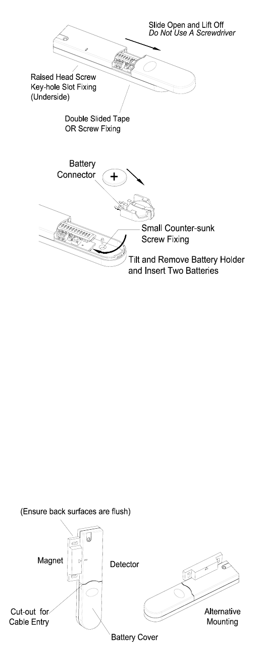
INSTALLING THE MAGNETIC CONTACT
DETECTORS
Ensure that the system is in Test Mode.
1. Remove the battery cover by sliding and lifting it off.
(DO NOT use a screwdriver to lever the cover off)
2. Remove the battery holder by carefully tilting up
the end and pulling the connector off of the printed
circuit board.
12
3. Mount the Detector to the fixed part of the frame
along the opening edge opposite the hinges using
either the double sided adhesive tape or screws
provided.
If fixing the Detector with screws; fit the Keyhole
slot in the top of the Detector over the head of the
smaller pan-head screw. Secure the bottom of
the Detector using the 12mm countersunk head
screw fitted within the battery compartment. You
will need to drill out the centre of the fixing screw
hole using a 3mm drill. Do not over-tighten the
fixing screws as this may distort or damage the
casing.
4. Fit the Magnet to the moving part of the
door/window opposite the Detector using the
adhesive tape or 15mm fixing screws. Ensure that
the parallel gap between the Magnet and Detector
is less than 10mm and that the arrow on the
Magnet is pointing towards and aligned with the
mark on the Detector.
5. If an additional wired Magnetic Contact is required,
this should be wired to the terminal block provided
in the battery compartment. The wired contact
should be connected using two core (24AWG) wire
of maximum length 1.5m.
A cable entry cut-out is provided beside the
terminal block in the battery cover.
6. Slide the batteries supplied into the battery holder,
ensuring that the positive (+) side is uppermost on
each battery as it is installed.
7. Carefully refit the battery holder onto the Detector
ensuring that the spring connectors slide onto
either side of the circuit board.
8. Refit the battery cover.
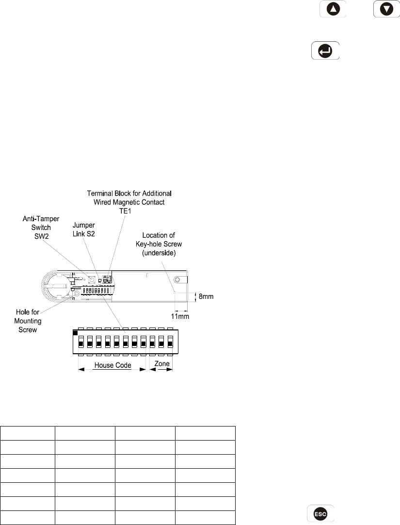
SETTING THE MAGNETIC CONTACT
DETECTORS
1. Located in the battery compartment is a row of 11
DIP switches.
2. DIP switches 1-8 are used to set the House Code
for the Magnetic Contact Detector and must be set
to the same ON/OFF combination as the House
Code DIP switches in all other system devices.
3. Configure the alarm zone which the detector will
operate on with DIP switches 9-11 as follows:
DIP 9 DIP 10 DIP 11
Zone 1 OFF OFF OFF
Zone 2 OFF OFF ON
Zone 3 OFF ON OFF
Zone 4 OFF ON ON
Zone 5 ON OFF OFF
Zone 6 ON OFF ON
Note: If the setting of DIP switches 9-11 does not
conform to any of the above mentioned six criteria,
the Control Panel cannot receive triggering signal
from the magnetic contact detector.
4. If additional external contacts are wired to the
Detector, remove the jumper link S2 on the PCB.
IMPORTANT: If external contacts are not
connected, then jumper link S2 must be fitted for
the detector to operate correctly.
TESTING THE MAGNETIC CONTACT
DETECTORS
Ensure that the system is in Test Mode
1. Use the and buttons to scroll
through the menu until ‘WALK TEST’ is displayed.
Press to activate Walk Test.
‘Walk Test Waiting…’ will be displayed.
2. Remove the battery cover by sliding off.
As the battery cover is removed the LED on the
Detector will illuminate for approx. 1 second to
indicate that the tamper switch has been activated.
In addition, the Control Panel will beep to indicate
that an alarm signal has been received and
‘Accessory Tamper’ will be displayed.
3. Open the door/window to detach the magnet from
the Detector. As the magnet is parted from the
detector the LED will illuminate for approx. 1
second to indicate that the Detector has been
triggered. In addition, the Control panel will beep
to indicate that an alarm signal has been received
and the identity of the zone that the detector is set
for will be displayed.
Note: In normal mode with the battery cover fitted,
the LED on the detector will not illuminate when
the detector is triggered, (unless the battery is
low).
4. If connected, operate the wired Magnetic Contact.
As the contact is opened the LED on the Detector
should illuminate for 1 second to indicate that it has
been triggered and the Control Panel will
acknowledge the alarm signal.
5. Refit the battery cover on the Detector.
6. Press to return to the top level menu of
TEST MODE.
13
5341 2
ON
8
ECE
67910 11
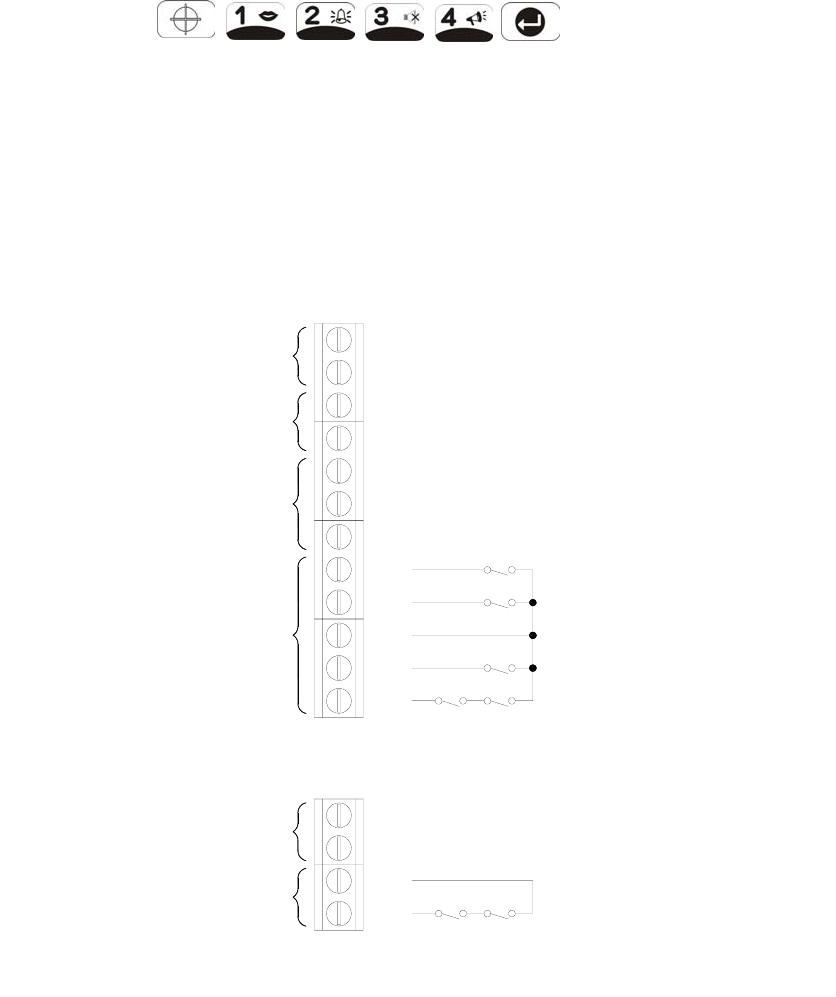
EXTERNAL CONNECTIONS
The Control Unit incorporates a terminal block for
connection of hard-wired Zones (7-10), Siren or
Telephone Dialer unit. The connection terminal block
is located inside the Control Panel behind the front
cover.
To access the terminal block
Press , ,
this puts the system into Test Mode and prevents an
alarm occurring. Undo the two fixing screws on the
top edge of the Control Panel and open the front cover.
Before making any connections, ensure that the
memory jumper link P1 is in the ‘OFF’ position and then
remove the DC power jack and disconnect one of the
back-up batteries.
Hardwired zone and tamper switches should be Volt
free and Normally Closed, with the contacts opening in
order to initiate an alarm.
Note: Jumper link P51 should be fitted into the ON
position only if the external hardwired tamper circuit is
used, otherwise it must be in the OFF position.
After making your external connections reconnect the
power supply and Back-up Battery. Then close the
14
Control Panel cover and tighten the fixing screws on
the top edge of the Control Panel.
Switched
12Vdc output for
external Siren
(300mA max.)
Permanent
12Vdc power
supply output
(100mA max.)
(Volt-free)
Latching
relay contacts
Normally-Closed
Connections
(Using
Hardwired Zone
T3(Zone 9)
T1(Zone 7)
T2(Zone 8)
contacts)
T4(Zone 10)
GND
OUT
V+
C
N.O.
GND
N.C.
T4
T3
T1
T2
GND
GND
B+
TAMP
GND
external devices
Tamper circuit
connections for
pack 12Vdc
Battery power
input
Terminal Block Detail

TESTING THE SYSTEM
INITIAL TESTING
As the system is initially installed it is recommended
that each device is tested in turn as it is installed, (refer
to testing instructions for particular device).
TESTING AN INSTALLED SYSTEM
The Control Panel has a programmed test routine.
You may test the system at any time, however it is
recommended that the system is tested at regular
intervals not exceeding 3 months.
With the system in Standby Mode
Press ,,
User Password
This puts the system into Test Mode.
The Arm and Part-Arm LEDs will flash.
The system is now in the Test Mode. If the battery
siren (HA301) is connected, the Control Panel will emit
disarm signal for 1.2 seconds. This offers the battery
siren to learn house code from the Control Panel.
Use the and buttons to scroll through
the menu and press to select the displayed
test function or sub-menu.
Note: After completing all required test functions, press
to leave Test mode and return to Standby.
WALK TEST
Before commencing testing, please ensure that there is
no movement in any PIR protected area, all
doors/windows protected by Magnetic Contact
Detectors are closed and that all battery covers and
housings are correctly fitted.
Scroll through the top level Test Mode menu until
‘WALK TEST’ is displayed and press .
‘Walk Test Waiting…’ will be displayed.
1. Trigger each detector on the system by either
walking into a PIR protected area or by opening a
door/window protected by a Magnetic Contact
detector. As each detector is triggered the Control
Panel will chime to indicate that an alarm signal has
been received and the identity of the zone that the
detector is configured for will be displayed.
2. Operate detector anti-tamper switches by opening
the case of the device. As the switches are
operated the Control Panel will chime and
‘Accessory Tamper’ will be displayed.
3. Activate each button on the Remote Control in turn.
As each button is pressed the Control Panel will
chime and the button name will be displayed. (e.g.
‘REMOTE CONTROL DISARM’).
Press to exit Walk Test and return to the top
level Test Mode menu.
ALARM TEST
Scroll through the top level Test Mode menu until
‘ALARM TEST’ is displayed and press .
Scroll though the menu until the required alarm
displayed and press to operate the selected
alarm for 5s.
Select ‘Wirefree Siren Test’ to operate the External
Solar Siren.
Select ‘Hardwired Siren Test’ to operate the Control
Panel Siren and external hardwired Siren (if
connected).
Select ‘Relay Test’ to operate the External hardwired
(N.O./N.C.) relay contacts.
Press to exit Alarm Test and return to the top
level Test Mode menu.
WIREFREE SIREN SERVICE ON/OFF
Scroll through the top level Test Mode menu until
‘Wirefree Siren Service ON/OFF’ is displayed and
press .
15
This offers the flexibility of removing or changing
siren’s battery. Wait for 10 seconds until ON/OFF
duration has elapsed, then go ahead with fixing the
siren as desired.
VOICE DIALER TEST
Scroll through the top level Test Mode menu until
‘VOICE DIALER TEST’ is displayed and press
.
In order to test the voice dialer properly, the
prerequisite is to set the telephone number, record the
message and enable the call routing in the
programming mode.
When testing is in progress, simply press to
stop testing.
If ‘LINE STATUS’ LED is flashing, it implies bad
telephone line connection or telephone network being
out of order. Check the telephone line and re-test it.
DIGITAL DIALER TEST
Scroll through the top level Test Mode menu until
‘DIGITAL DIALER TEST’ is displayed and press
.
In order to test the digital dialer properly, the
prerequisite is to set the telephone number and unit ID
number in the programming mode.
When testing is in progress, simply press to
stop testing.
If ‘LINE STATUS’ LED is flashing, it implies two causes
of failure. One is bad telephone line connection or
telephone network being out of order. The other cause
of failure is derived from the central monitoring station.
Consult with the central monitoring station for help.
DEFAULT SETTINGS
User Setup
Users 1-6: Not programmed
Master Password 1234
16
System Setup
House Code 10101010
Alarm Time ON, 180s
Wirefree Siren ON
RF Jamming Detection OFF
Back Light 10s
Alarm Relay On Until Disarm
Zone Lockout ON
Remote Phone Control ON
Rings to Answer Phone 6
Call Abort OFF
Dial method Tone/DTMF
Dialer Mode Voice Dialer
Time 12:00:00
Date 01/01/03
Zone Setup (Z1-10)
Name No Name
Type Intruder
Final Exit OFF
Chime OFF
Entry Delay Zone 1
Zone 2-10
ON, 30s
OFF
Part-Arm 1 OFF
Part-Arm 2 OFF
Walk Through OFF
Voice Dialer Setup
Phone Numbers Not programmed
Message Play Time 70s
Alarm Messages Not programmed
Call Routing All numbers disabled
Call Confirms 1
Call Attempts 3
Full Arm Setup
Exit Delay ON, 30s
Entry Delay Beep ON
Exit Delay Beep ON
Part-Arm 1 Setup
Exit Delay ON, 30s
Entry Delay Beep ON
Exit Delay Beep ON
Part-Arm 2 Setup
Exit Delay ON, 30s
Entry Delay Beep ON
Exit Delay Beep ON
Latchkey Setup
Status OFF
Selected User Setup OFF (all users)
Phone Numbers Not programmed
Home Control Setup
House Code A
Unit 1-8 Setup(Unit Code) 01-08
Alarm Trigger OFF
Answer Phone Setup
Status OFF
Greeting Message Not programmed
Digital Dialer Setup
Phone No. Not programmed
Unit ID No. Not programmed
Call Attempts 3
Open/Close by user OFF
RESET FACTORY DEFAULT
1. Press
,
User Password
to place the system in Test Mode.
2. Undo the Control Panel cover fixing screws and
open the cover.
3. Switch OFF the mains supply to the plug-in PSU
Adaptor and remove the plug from the DC power
socket in the Control Panel.
4. Remove either back-up battery and disconnect the
battery leads.
5. Set jumper link P1 to the ON position.
6. Reconnect the battery leads and replace the
back-up battery in position.
Reconnect the PSU Adaptor plug to the DC power
socket in the Control Panel and switch On the
supply to the PSU Adaptor.
7. As the Control Panel powers-up, ‘EEPROM RESET’
will be displayed while the factory default conditions
are restored to memory. Once the memory reset
has been completed ‘DISARM READY’ will be
displayed. The Control Panel will now be
reconfigured with all factory default settings.
8. Reset jumper link P1 into the OFF position.
9. Close the Control Panel cover and refit the fixing
screws.
17
PROGRAMMING INSTRUCTIONS
With the system in Standby Mode.
Press ,
Master Password
The system is now in the Programming Mode
Use the and buttons to scroll through
the programming menu. Press to select the
displayed programming function or sub-menu.
Note: After programming all required functions press
to leave Programming mode and return to
Standby.
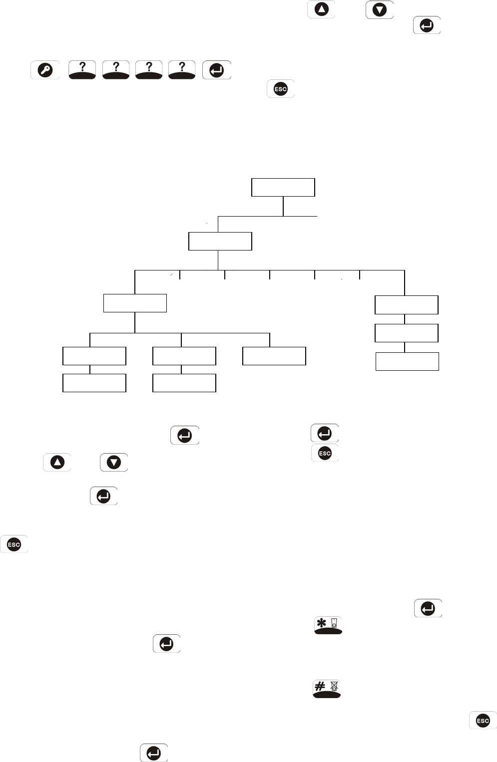
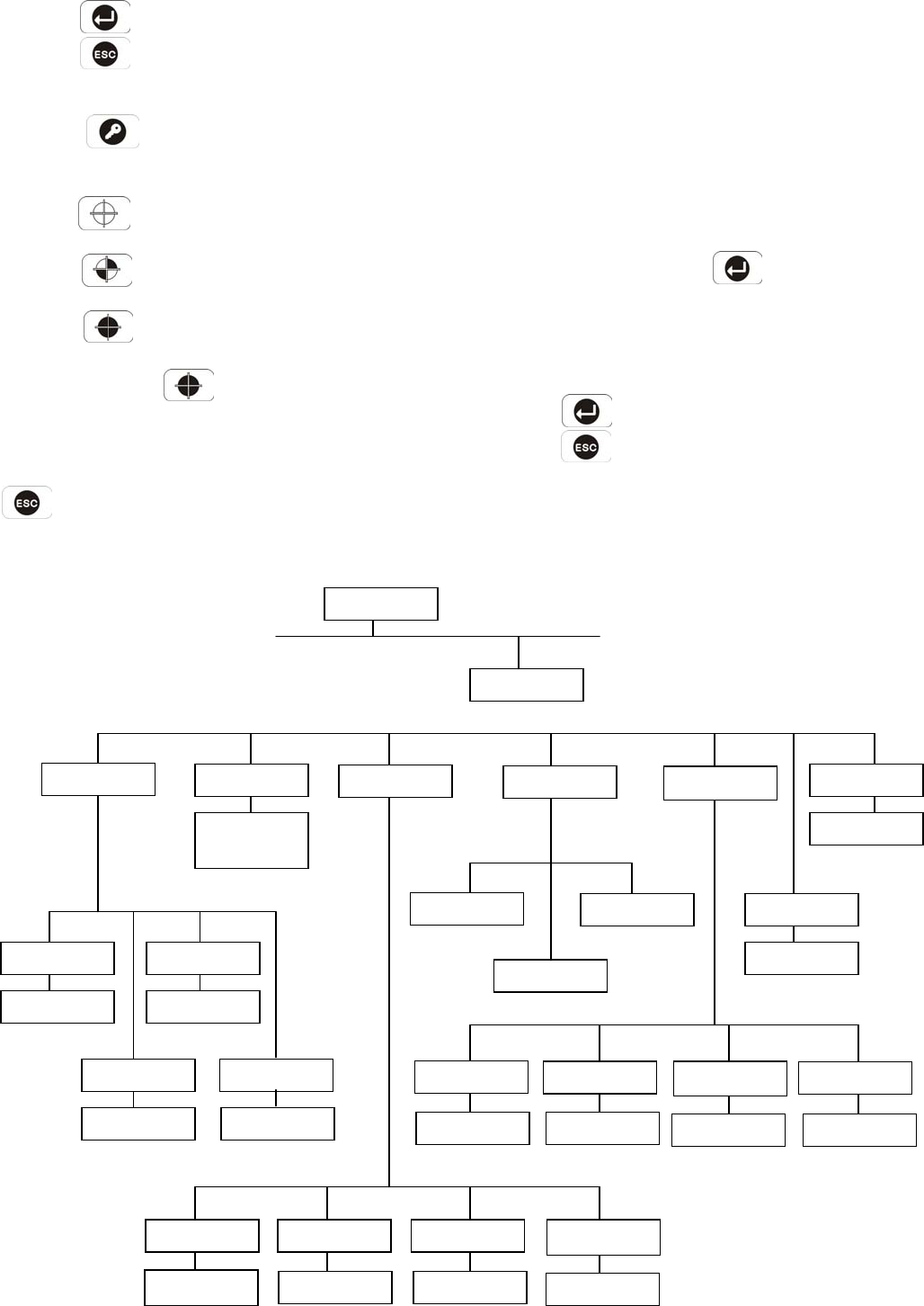
USER SETUP
Scroll through the top level programming menu until ‘1.
USER SETUP’ is displayed and press .
Use the and buttons to scroll through
the menu until the required user to be configured is
displayed and press .
Note: After configuring all required users press
to return to the top level programming menu.
USERS 1-6
Default setting: not programmed
Scroll through the menu until the required User to be
configured is displayed and press .
User Password
Scroll through the menu until ‘:1 Password’ is
displayed. The current setting will also be
displayed.
To change the setting press
18
Enter the new 4 digit Password and then
Press to save and exit, or
Press to exit without saving.
Record User Message
This enables each User to record a short 4s message
for use with the latchkey facility. e.g. “system disarmed
by User-1”.
Scroll through the menu until ‘:2 Record User
Message’ is displayed.
To record a new message press .
Press to start the voice recorder, (max.
duration: 4s) Once completed the recording will
automatically be played back, or
Press to exit without changing.
Note: After recording the message, press to
stop the recorder and cancel any remaining
message time.
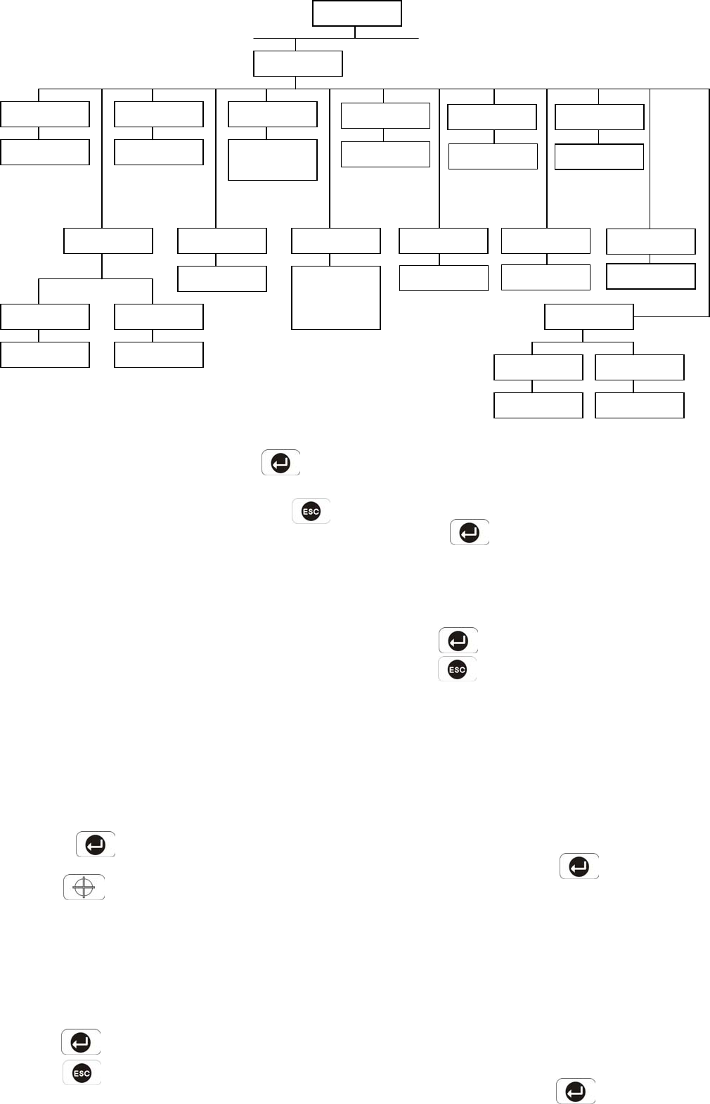
PROGRAM MODE
Code:
1. USER SETUP
1-1 USER 1 SETUP
:1 Password
xxxx
Enter Password
Code:
:2 Record
User Message
Start…
Yes
->
*
No
->
#
:3 Replay
User Message
1-7 MASTER USER
SETUP
:1 Password
1234
Enter Password
Code:
User 2 User 3 Use
r
4 User 5 User 6
Replay User Message
Scroll through the menu until ‘:3 Replay User
Message’ is displayed.
Press to replay the user message.
Press to return to the top level User-Setup
menu.
MASTER USER
Default Password: 1234
Scroll through menu until ‘1-7 MASTER USER
SETUP’ is displayed and press .
‘:1 Password’ and the current setting will be
displayed.
To change the setting press .
Type in a new 4 digit Password, and then
Press to save and exit, or
Press to exit without saving.
Press to return to the top level User-Setup
menu.
19
SYSTEM SETUP
Scroll through the top level programming menu until ‘2
SYSTEM SETUP’ is displayed and press .
Note: After completing the system setup press
to return to the top level programming menu.
LEARN SYSTEM HOUSE CODE
There are two methods to learn the House Code. One
is to have the Control Panel learn the system house
code through the remote control. The other is to
press the Control Panel’s keypad 1-8 by selecting 0 or
1 respectively in turn (0 means the dip switch is set in
ON position, 1 is set in OFF position).
1. Scroll through the menu until ‘2-1 Learn House
Code’ is displayed.
To program the Control Panel with the system House
Code press
Press on the Remote Control
The new programmed system house code will be
recorded into memory and displayed on the bottom
line of the LCD, with the corresponding DIP switch
number shown on the top line.
Press to save and exit, or
Press to exit without saving.
20
2. Scroll through the menu until ‘2-1 Learn House
Code’ is displayed.
To program the Control Panel with the system House
Code press .
Press the Control Panel’s keypad 1-8 by selecting 0 or
1 respectively in turn.
Press to save and exit, or
Press to exit without saving.
Make a note of the system house code now in the
space provided on page 41.
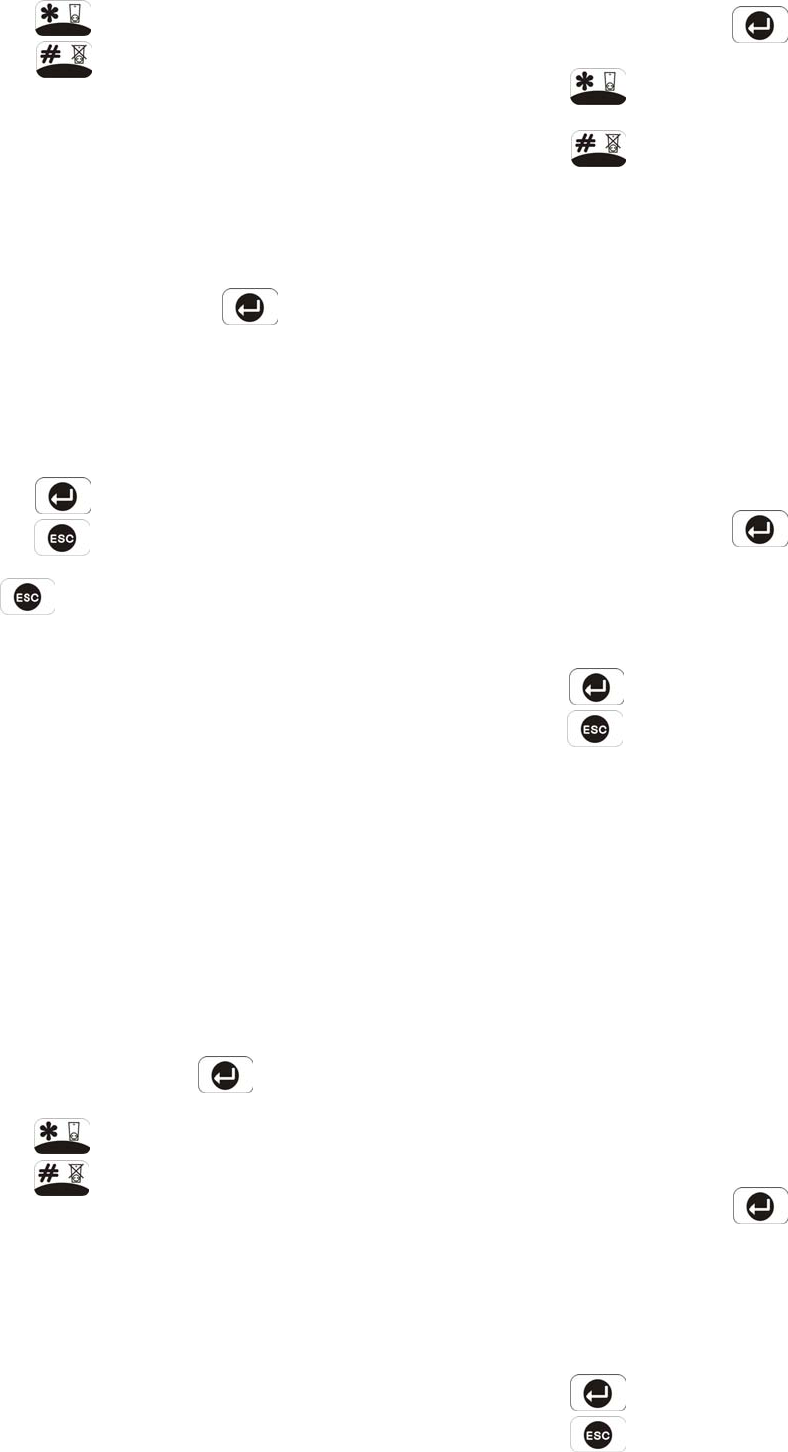
ALARM DURATION
Scroll through the menu until ‘2-2 ALARM TIME’ is
displayed. The current settings will also be displayed.
To change the settings press .
On/Off Status
Default setting: ON
Scroll through the menu until ‘2-2-1 Status’ is
displayed. The current settings will also be
displayed.
To change the setting press
2. SYSTEM SETUP
2-1 Learn House
Code
DIP SW: 12345678
H Code: xxxxxxxx
2-3 Wirefree
Siren: xx
Select
ON
->
*
OFF
->
#
2-5 Back Light
xxs
2-7 Zone Lockout
xx
2-9 Rings to
Answer Phone: xx
2-11 Dial Method
xxxxxxxx
2-2 ALARM TIME
xx : xxxx
2-4 RF Jamming
Detection: xxx
2-2-1 Status
xx
Select
ON
->
*
OFF
->
#
2-2-2 Time
Enter
1
-
60(x10)s
Enter 1-60(x10)s
2-6 Alarm Relay
xx xxxxx xxxxx
2-8 Remote Phone
Control: xx
2-10 Call Abort
xxx
2-12 Dialer Mode
xxxxx xxxxxx
Select
ON
->
*
OFF
->
#
Select
ON
->
*
OFF
->
#
Tone/DTMF
Pulse
2s
30s
60s
180s
300s
ON Until Disarm
Select
ON
->
*
OFF
->
#
Select
ON
->
*
OFF
->
#
Voice Dialer
Digital Dialer
10s
20s
30s
60s
PROGRAM MODE
Code:
2-13 TIME & DATE
SETUP
2-13-1 Date
DD/MM/YY DDD
DD/MM/YY
2-13-2 Time
HH/MM/SS
HH/MM/SS
Enter 1-30:
Press to enable the Siren, or
Press to disable the Siren
Alarm Duration
Default setting: 180s
Scroll through the menu until ‘2-2-2 Time’ is
displayed.
To change the setting press .
Enter the required alarm duration in units of 10s.e.g.
enter 6 for a 60s alarm duration (max setting 60, i.e.
600s/10mins).
Press to save and exit, or
Press to exit without saving.
Press to return to top level System Setup menu.
Note: Following initiation of a Full Alarm condition the
External Siren will continue to sound until either the
system is disarmed; or the Control Panel Alarm
Duration Time expires; or if activated until the 3 minute
alarm time limit of the external Siren expires; whichever
occurs first.
WIREFREE SOLAR SIREN
Default setting: ON
Scroll through the menu until ‘2-3 Wirefree Siren’ is
displayed. The current setting will also be displayed.
To change the setting press .
Press to enable the Solar Siren, or
Press to disable the Solar Siren.
JAMMING DETECTION
This feature controls the Control Panels RF jamming
detection circuitry, which if enabled, will continuously
scan for radio jamming signals on the system operating
frequency.
Default setting: OFF
Scroll through the menu until ‘2-4 RF Jamming
Detection’ is displayed. The current setting will also
be displayed.
To change the setting press .
Press to enable Jamming Detection, or
Press to disable Jamming Detection.
CONTROL PANEL BACK LIGHT
This controls the time period that the backlight for the
Control Panel display will stay illuminated for after the
last key is pressed.
Default setting: 10s
Scroll through the menu until ‘2-5 Back Light’ is
displayed. The current setting will also be displayed.
To change the setting press .
Scroll through available options, (10, 20, 30 and
60s) until the required setting is displayed.
Press to save and exit, or
Press to exit without saving.
ALARM RELAY
This setting controls the operation period for the
NO/NC hardwired output relay contacts following an
alarm condition being initiated.
If this is set to ‘ON until Disarm’ then the relay will
latch and remain On until the system is next disarmed.
Default setting: ON Until Disarm
Scroll through the menu until ‘2-6 Alarm Relay’ is
displayed. The current setting will also be displayed.
To change the setting press
Scroll through available options, (2s, 30s, 60s,
180s, 300s and ‘ON Until Disarm’) until the
required setting is displayed and then
Press to save and exit, or
Press to exit without saving.
21

ZONE LOCKOUT
This feature, if enabled, prevents a single zone from
triggering an alarm condition more than three times
before the system is disarmed. However, if disabled,
there is no limit on the number of times a zone can
trigger an alarm condition.
Default setting: ON
Scroll through the menu until ‘2-7 Zone Lockout’ is
displayed. The current setting will also be displayed.
To change the setting press .
Press to enable Zone Lockout, or
Press to disable Zone Lockout.
REMOTE SYSTEM CONTROL
This feature, if enabled, allows the system to be
remotely controlled via the telephone.
Default setting: ON
Scroll through the menu until ‘2-8 Remote Phone
Control’ is displayed. The current setting will also be
displayed.
To change the setting press .
Press to enable Remote Phone Control, or
Press to disable Remote Phone Control.
RINGS TO ANSWER PHONE
This controls the number of times a connected phone
will be allowed to ring before the line is picked up for
either Answer-Phone and/or Remote Phone Access
use.
Default setting: 6
To change the setting press .
Enter the required number of rings (1-30) before the
Control panel will pick up the call
Press to save and exit, or
Press to exit without saving.
22
CALL ABORT
This feature, if enabled, will delay the activation of the
telephone dialer following an alarm for a period of
approx. 30s to allow the system to be disarmed.
Default setting: OFF
Scroll through the menu until ‘2-10 Call Abort’ is
displayed. The current setting will also be displayed.
To change the setting press .
Press to enable Call Abort, or
Press to disable Call Abort.
DIAL METHOD
This feature enables the telephone dialer to be
configured for type of exchange it is connected to.
Default setting: Tone/DTMF
Scroll through the menu until ‘2-11 Dial Method’ is
displayed. The current setting will also be displayed.
To change the setting press .
Scroll through available options, (Tone/DTMF and
Pulse), until the required setting is displayed and
then
Press to save and exit, or
Press to exit without saving.
DIAL MODE
This facility controls whether the internal telephone
dialer operates with the voice or digital dialer facility.
The digital dialer is designed to be connected to an
external remote Central Monitoring station service.
Default setting: Voice Dialer
Scroll through the menu until ‘2-12 Dialer mode’ is
displayed. The current setting will also be displayed.
To change the setting press .
Scroll through available options, (Voice dialer and
Digital dialer) until the required setting is displayed.
Press to save and exit, or
Press to exit without saving.
TIME & DATE SETUP
Scroll through the menu until ‘2-13 TIME & DATE
SETUP’ is displayed and press .
Note: After configuring the Time and Date press
to return to the top level programming menu.
DATE
Scroll through the menu until ‘2-13-1 Date’ is displayed.
The current setting will also be displayed.
To change the setting press .
Enter the date in the format ‘dd/mm/yy’.
Press to save and exit, or
Press to exit without saving.
TIME
Scroll through the menu until ‘2-13-2 Time’ is
displayed. The current setting will also be displayed.
To change the setting press
Enter the time in the format ’hh:mm:ss’.
Press to save and exit, or
Press to exit without saving.
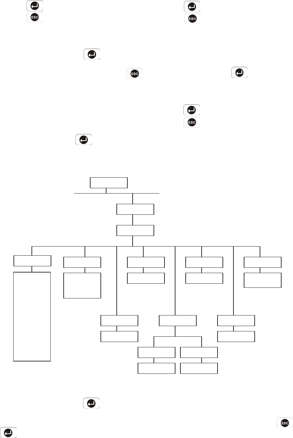
ZONE SETUP
Scroll through the programming menu until ‘3. ZONE
SETUP’ is displayed and press .
Enter the zone number to be configured and press
.
The following configuration options are based upon
configuring zone 1. Options for all other zones (2-10)
are identical except the zone number reference will
change according to the zone being configured.
Note: After completing the Zone Setup press
to return to the top level programming menu.
23
3. ZONE SETUP:
Enter Zone (1-10)
3-1 Zxx Name
xxxxxxxxxxxxxx
3-2 Zxx Type
xxxxxxxxxxxxxx
3-4 Zxx Chime
xxxx
3-6 Zxx
PART
-
ARM 1: XXX
3-8 Zxx Walk
Through: xxx
Panic/PA
Intruder
24 hour Intruder
Fire
Tes t
Select
ON
->
*
OFF
->
#
Select
ON
->
*
OFF
->
#
OFF
Slave
Master
3-3 Zxx Final
Exit Set: xxx
Select
ON
->
*
OFF
->
#
3-7 Zxx
PART
-
ARM 2: XXX
3-5 Zxx ENTRY
DELAY: XXX XXX
Select
ON
->
*
OFF
->
#
3-5-1 Status
xxx
3-5-2 Delay Time
Enter (10
-
250s)
Enter (10-250s)
Select
ON
->
*
OFF
->
#
No name
Front door
Back door
Patio door
Dining room
Living room
Lounge
Kitchen
Shed
Garage
Hall
Landing
Upstairs
Downstairs
Bedroom 1
Bedroom 2
Bedroom 3
Bedroom 4
Windows 1
Windows 2
Windows 3
PIR Detector
Magnetic Contact
FIRE/SMOKE
Panic/PA
PROGRAM MODE
Code:

NAME
Default setting: ‘No name’
Scroll through the menu until ‘3-1 Z01 Name’ is
displayed. The current setting will also be displayed.
To change the setting press .
Scroll through available options until the required
setting is displayed.
Press to save and exit, or
Press to exit without saving.
TYPE
Each alarm zone may be programmed to operate in
one of 5 different modes depending on the type of
alarm function it is required to perform. The following
alarm types are available:
Panic
- used to provide 24 hour monitoring of any emergency
being occurred. Activation of any Panic switch will
immediately initiate a Full Alarm condition.
Intruder
- provides standard intruder monitoring with normal
ARM and PART-ARM functions.
24 Hour Intruder
- used to provide 24 hour monitoring of areas requiring
continuous security protection even while the system
is Disarmed, (e.g. gun lockers). Activation of any
detector on a security zone will immediately initiate a
Full Alarm condition.
Fire
- use to provide 24 hour monitoring of any
Fire/Smoke detectors fitted to the system.
Activation of any detector will immediately initiate a
Full Alarm condition.
Test
- when the system is armed, any detector on the
zone will generate an entry in the Event-Log
without initiating an alarm condition.
24
Note: Panic, 24-hour Intruder and Fire modes all
operate on a 24 hour basis, (i.e. they are able to initiate
Full Alarm condition at any time irrespective of whether
the system is Armed or Disarmed).
Default setting: ‘Intruder’
Scroll through the menu until ‘3-2 Z01 Type’ is
displayed. The current setting will also be displayed.
To change the setting press .
Scroll through available options until the required
setting is displayed.
Press to save and exit, or
Press to exit without saving.
FINAL EXIT SET
If enabled, triggering of any detector on the zone
during the exit-delay will cancel any remaining
exit-delay and cause the system to arm 5 seconds
later.
Default setting: OFF
Scroll through the menu until ‘3-3 Z01 Final Exit Set‘ is
displayed. The current setting will also be displayed.
To change the setting press .
Press to enable the zone’s Final Exit Set
facility, or
Press to disable the zone’s Final Exit Set
facility.
CHIME
This controls whether the Chime facility is available on
the zone.
Default setting: OFF
Scroll through the menu until ‘3-4 Z01 Chime’ is
displayed. The current setting will also be displayed.
To change the setting press .
Press to enable the zone’s Chime facility, or
Press to disable the zone’s Chime facility.
ENTRY DELAY
Scroll through the menu until ‘3-5 ENTRY DELAY’ is
displayed. The current settings will also be displayed.
To change the settings press .
On/Off Status
Default setting: Zone 1: ON
ZONES 2-10: OFF
Scroll through the menu until ‘3-5-1 Status’ is
displayed. The current setting will also be displayed.
To change the settings press .
Press to enable the zone’s entry-delay, or
Press to disable the zone’s entry-delay.
Delay Period
Default setting: 30s
Scroll through the menu until ‘3-5-2 Delay Time’ is
displayed.
To change the settings press .
Enter the required delay period (10 to 250s)
Press to save and exit, or
Press to exit without saving.
Press to return to top level Zone Setup.
PART-ARM 1
This controls whether the zone is active when Part-Arm
1 is armed.
Default setting: OFF
Scroll through the menu until ‘3-6 Z01 Part-Arm 1’ is
displayed. The current setting will also be displayed.
To change the setting press .
Press to enable the Zone in Part-Arm 1, or
Press to disable the Zone in Part-Arm 1.
PART-ARM 2
This controls whether the zone is active when Part-Arm
2 is armed.
Default setting: OFF
Scroll through the menu until ‘3-7 Z01 Part-Arm 2’ is
displayed. The current setting will also be displayed.
To change the setting press .
Press to enable the Zone in Part-Arm 2, or
Press to disable the Zone in Part-Arm 2.
WALK THROUGH
Default setting: OFF
Scroll through the menu until ‘3-8 Z01 Walk Through’
is displayed. The current setting will also be
displayed.
To change the setting press .
Scroll through available options, (Off, Master and
Slave), until the required setting is displayed.
Press to save and exit, or
Press to exit without saving.
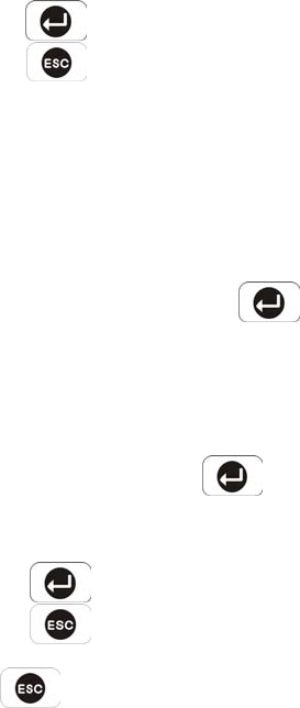
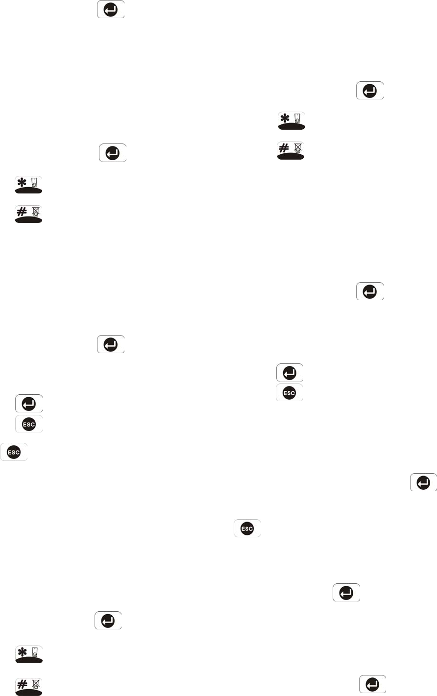
VOICE DIALER SETUP
See diagram on next page.
Scroll through the programming menu until ‘4. VOICE
DIALER SETUP’ is displayed and press .
Note: After completing the Voice Dialer Setup press
to return to the top level programming menu.
TELEPHONE NUMBERS
Scroll through the menu until ‘4-1 PHONE NUMBERS’
is displayed and press .
Scroll through the menu until the required Telephone
number (1-4) is displayed. The current setting of each
telephone number will also be displayed.
To change the number press .
25
Enter the new telephone number (32 digits max.)
Press to save and exit, or
Press to exit without saving.
Notes:
Press to insert a 3.6s pause in the dialing
sequence.
Press to move the cursor left.
Press to move the cursor right.
Press to delete the character under the
cursor.
Press and hold to erase the entire phone
number.
After programming all required phone numbers press
to return to the top level Voice Dialer menu.
ALARM MESSAGE PLAY TIME
This is the total time for which the alarm messages will
be played & repeated when a call made by the voice
dialer is answered.
Default setting: 70s
Scroll through the menu until ‘4-2 Message Play Time’
is displayed. The current setting will also be
displayed.
To change the settings press .
Scroll through the available options, (50, 70, 90 and
110s) until the required setting is displayed.
Press to save and exit, or
Press to exit without saving.
26
4-1-1 Phone No. 1
xxxxxxxxxxxxxxxxx
Enter 1-5:
4-2 Message
Play Time: xxxx
4. VOICE DIALER
SETUP
PROGRAM MODE
C
ode:
4-1 PHONE
NUMBERS
4-3 RECORD
ALARM MESSAGES
4-4 REPLAY ALARM
MESSAGES
4-5 CALL ROUTING
XXXX
4-7 Call
Attempts: x
4-6 Tel Confirm
Times: x
Enter Phone No:
4-1-3 Phone No. 3
xxxxxxxxxxxxxxxxx
Enter Phone No:
4-1-2 Phone No. 2
xxxxxxxxxxxxxxxxx
4-1-4 Phone No. 4
xxxxxxxxxxxxxxxxx
Enter Phone No. Enter Phone No: Select
YES
->
*
NO
->
#
4-5-2 Phone No. 2
xxx
Select
YES
->
*
NO
->
#
4-5-1 Phone No. 1
xxx
Select
YES
->
*
NO
->
#
Select
YES
->
*
NO
->
#
4-5-3 Phone No. 3
xxx
4-5-4 Phone No. 4
xxx
4-4-1 Main +
Intruder Message
4-4-3 Main +
Panic/PA Message
Enter 1-4:
4-4-2 Main +
Fire Message
50s
70s
90s
110s
Start
YES->* NO->#
4-3-1 Main
Alarm Message
4-3-3Fire
Alarm Message
Start
YES
->
*
NO
->
#
4-3-2 Intruder
Alarm Message
4-3-4 Panic/PA
Alarm Message
Start
YES
->
*
NO
->
#
Start
YES
->
*
NO
->
#

RECORD ALARM MESSAGES
Scroll through the menu until ‘4-3 RECORD VOICE’ is
displayed and press .
Scroll through the available menu options until the
required message type to be recorded is displayed.
a) Main Alarm message, (12 seconds max).
b) Intruder Alarm message, (4 seconds max).
c) Fire Alarm message, (4 seconds max).
d) Panic Alarm message, (4 seconds max).
To record a new message press .
Press to start the voice recorder. Once
completed the recording will automatically be
replayed, or
Press to exit without changing.
Note: After recording the message, press to
stop the recorder and cancel any remaining message
time.
Press to return to the top level Voice Dialer setup
menu.
REPLAY ALARM MESSAGES
Scroll through the menu until ‘4-4 REPLAY ALARM
MESSAGES’ is displayed and press .
Scroll through the available menu options until the
required message type is displayed.
a) Main + Intruder Messages
b) Main + Fire Messages
c) Main + Panic Messages
To replay the message press .
Press to return to the top level Voice Dialer setup
menu.
CALL ROUTING
This feature controls which telephone numbers are
enabled in the dialing sequence and are dialed when
the voice dialer is activated.
The current routing sequence is displayed on screen in
the order of phone numbers 1-4. An ‘X’ indicates the
number is disabled and a ‘O’ indicates the number is
enabled in the routing sequence. e.g. A display =
“000x” indicates a call sequence of phone nos.1,2 and
3, phone number 4 is disabled and not called.
Default setting: all numbers disabled.
Scroll through the menu until ‘4-5 CALL ROUTING’ is
displayed. The current settings will also be displayed.
Scroll through the available menu options until the
required telephone number (1-4) to be configured is
displayed. The current status will also be displayed.
To change the setting press .
Press to enable the number in the routing
sequence, or
Press to disable the number in the routing
sequence.
Press to return to the top level Voice Dialer
Setup menu.
TEL CONFIRM TIMES
This sets the number of acknowledged phone numbers
required to stop the voice dialer. For example if set to
“2” then the dialing sequence will continue until an
acknowledgment is received from two different
numbers, (e.g. Phone No. 1 and Phone No. 3).
Default setting: 1
Scroll through the menu until ‘4-6 Tel Confirm Times’
is displayed. The current settings will also be
displayed.
To change the setting press .
Enter the required number (1-4).
Press to save and exit, or
Press to exit without saving.
CALL ATTEMPTS
This sets the maximum number of times that the dialer
will attempt to contact each enabled telephone number
in the call routing sequence.
27
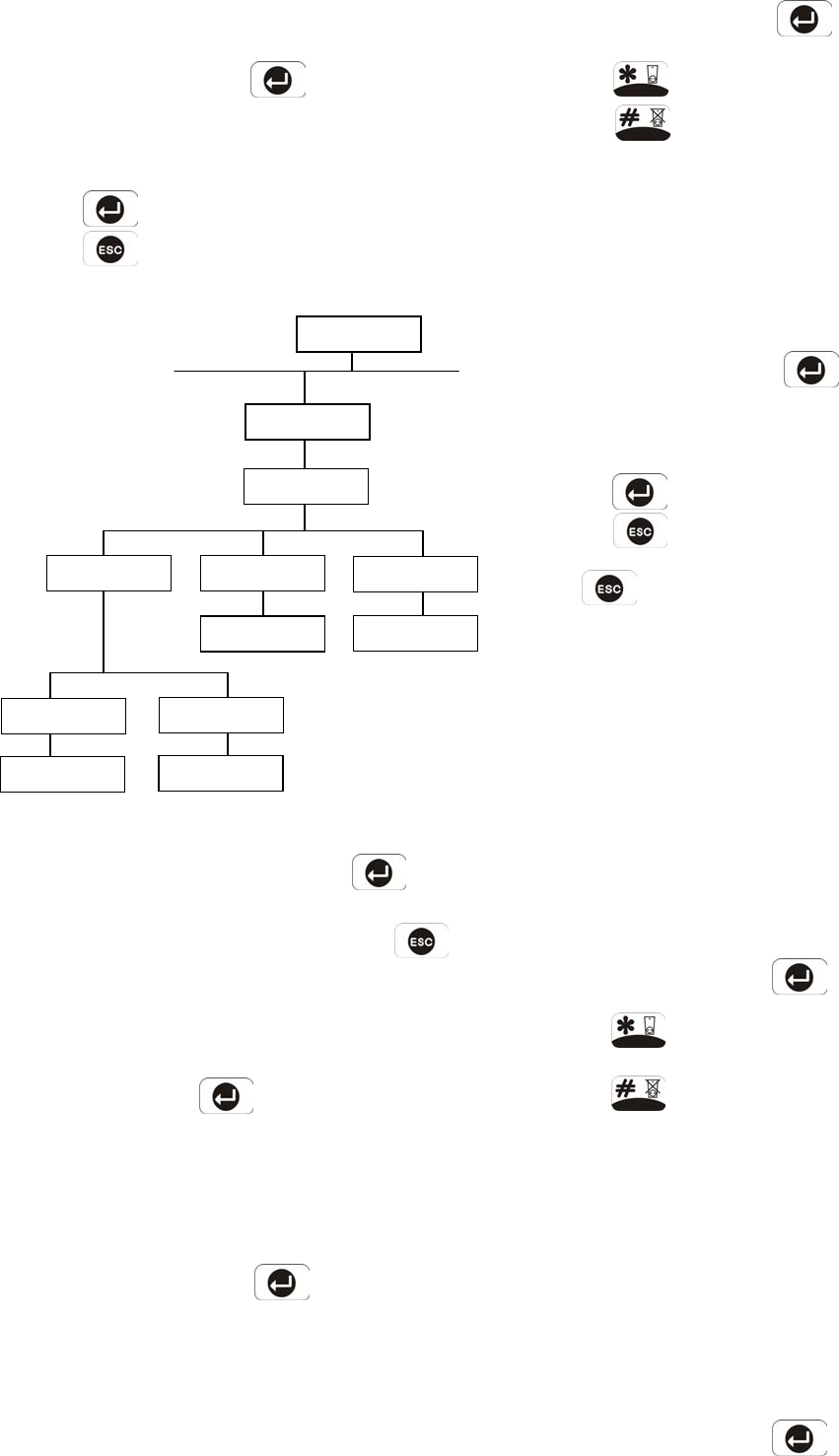
Default setting: 3
Scroll through the menu until ‘4-7 Call Attempts’ is
displayed. The current settings will also be displayed.
To change the setting press .
Enter the required number (1-5).
Press to save and exit, or
Press to exit without saving.
ARM STATUS SETUP
Scroll through the programming menu until ‘5. ARM
STATUS SETUP’ is displayed and press .
Note: After configuring Arm Status press to
return to the top level programming menu.
FULL ARM SETUP
Scroll through the menu until ‘5-1 FULL ARM SETUP’
is displayed and press
EXIT DELAY
Scroll through the menu until ‘:1 EXIT DELAY’ is
displayed. The current settings will also be displayed.
To change the settings press .
On/Off Status
Default setting: ON
28
Scroll through the menu until ‘:1-1 Status’ is displayed.
The current setting will also be displayed.
To change the settings press .
Press to enable the Exit delay, or
Press to disable the Exit delay.
Delay Period
Default setting: 30s
Scroll through the menu until ‘:1-2 Delay Time’ is
displayed. The current settings will also be displayed.
To change the settings press .
Enter the required delay period (10 to 250s).
Press to save and exit, or
Press to exit without saving.
Press to return to top level Arm Status Setup
menu.
ENTRY DELAY BEEP
This controls the warning beep which operates during
the Entry Delay period when Full Arm is active.
Default setting: ON
Scroll through the menu until ‘:2 Entry Delay Beep’ is
displayed. The current setting will also be displayed.
To change the setting press .
Press to enable the entry-delay beep, or
Press to disable the entry-delay beep.
EXIT DELAY BEEP
This controls the warning beep which operates during
the Exit Delay period when Full Arm is initiated.
Default setting: ON
Scroll through the menu until ‘:3 Exit Delay Beep’ is
displayed. The current setting will also be displayed.
To change the setting press .
:3 Exit Delay
Beep: xxx
:2 Entry Delay
Beep: xxx
:1 EXIT DELAY
XX XXX
5. ARM STATUS
SETUP
PROGRAM MODE
Code:
:1-2 Delay Time
Enter (10
-
250s)
Select
ON
->
*
OFF
->
#
Select
ON
->
*
OFF
->
#
Enter (10-250s)
:1-1 Status
xx
Select
ON
->
*
OFF
->
#
5-1 FULL ARM
SETUP
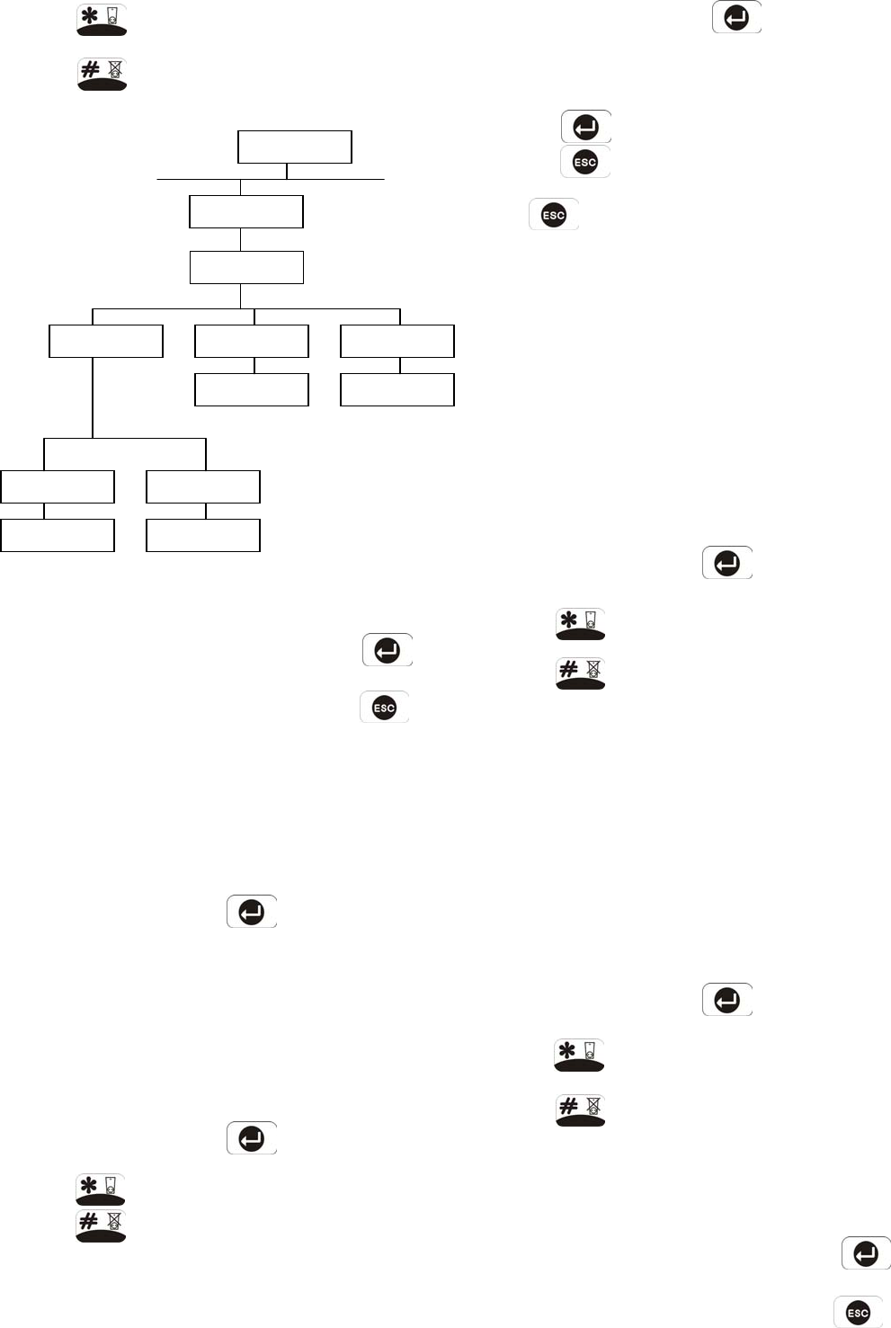
Press to enable the exit-delay beep, or
Press to disable the exit-delay beep.
PART-ARM 1 SETUP
Scroll through the programming menu until ‘5-2
PART-ARM 1 SETUP’ is displayed and press .
Note: After configuring Part-Arm 1 press to
return to the top level programming menu.
EXIT DELAY
Scroll through the menu until ‘:1 EXIT-DELAY’ is
displayed. The current settings will also be displayed.
To change the settings press .
On/Off Status
Default setting: ON
Scroll through the menu until ‘:1-1 Status’ is displayed.
The current setting will also be displayed.
To change the settings press .
Press to enable the Exit delay, or
Press to disable the Exit delay.
Delay Period
Default setting: 30s
Scroll through the menu until ‘:1-2 Delay Time’ is
displayed. The current settings will also be displayed.
To change the settings press .
Enter the required delay period (10 to 250s).
Press to save and exit, or
Press to exit without saving.
Press to return to top level Part-Arm 1 Setup
menu.
ENTRY DELAY BEEP
This controls the warning beep which operates during
the Entry Delay period when Part-Arm 1 is active.
Default setting: ON
Scroll through the menu until ‘:2 Entry Delay Beep’ is
displayed. The current setting will also be displayed.
To change the setting press .
Press to enable the entry-delay beep, or
Press to disable the entry-delay beep.
EXIT DELAY BEEP
This controls the warning beep which operates during
the Exit Delay period when Part-Arm 1 is initiated.
Default setting: ON
Scroll through the menu until ‘:3 Exit Delay Beep’ is
displayed. The current setting will also be displayed.
To change the setting press .
Press to enable the exit-delay beep, or
Press to disable the exit-delay beep.
PART-ARM 2 SETUP
See diagram on next page.
Scroll through the programming menu until ‘5-3
PART-ARM 2 SETUP’ is displayed and press .
Note: After configuring Part-Arm 2 press to
return to the top level programming menu.
29
Select
O
N
->
*
OFF
->
#
:3 Exit Delay
Beep: xxx
:2 Entry Delay
Beep: xxx
:1 EXIT DELAY
XXX XXX
5-2 PART-ARM 1
SETUP
PROGRAM MODE
Code:
Select
ON
->
*
OFF
->
#
Select
ON
->
*
OFF
->
#
:1-1 Status
xxx
Enter (10-250s)
:1-2 Delay Time
Enter (10
-
250s)
5. ARM STATUS
SETUP
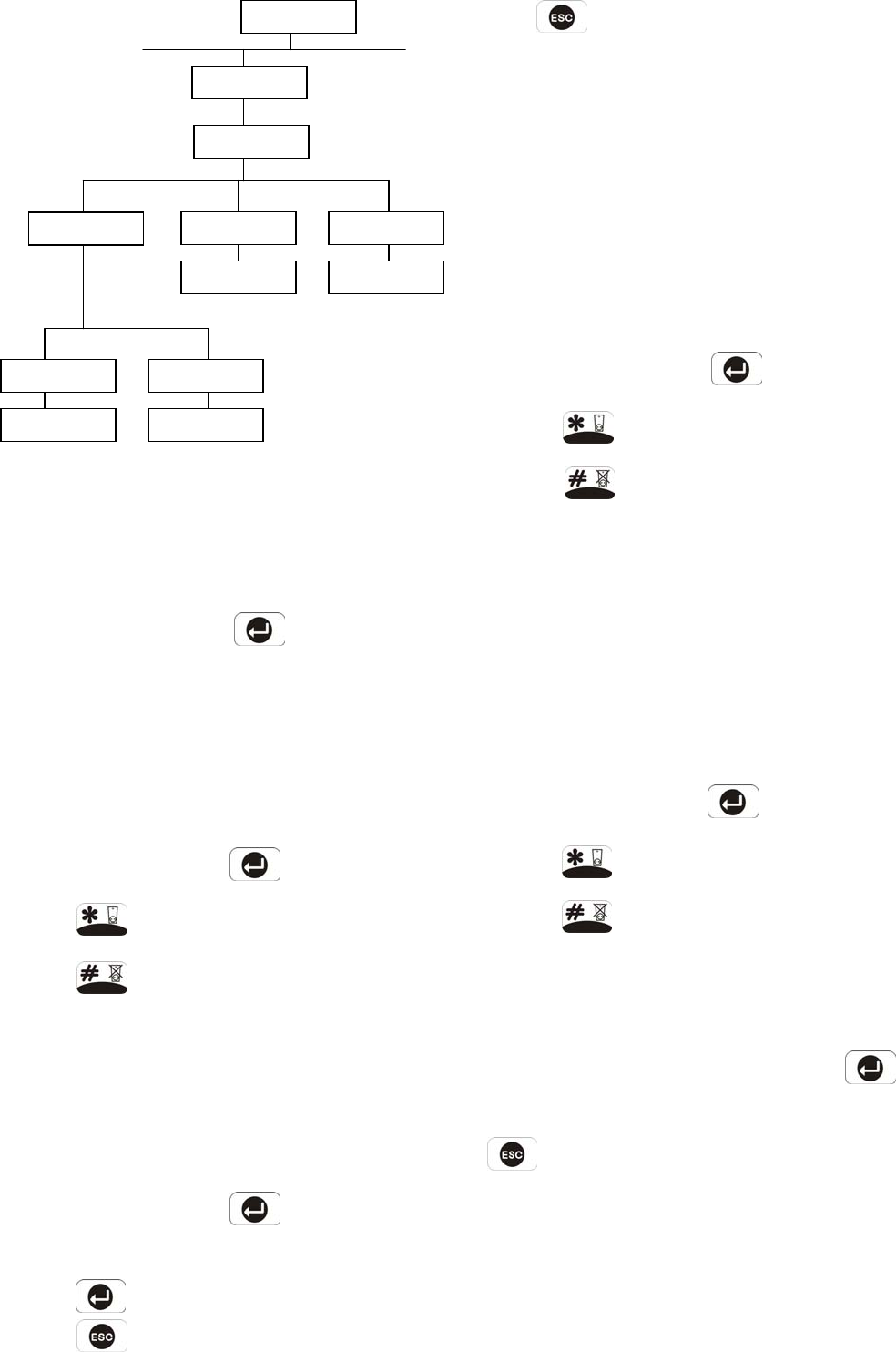
EXIT DELAY
Scroll through the menu until ‘:1 EXIT-DELAY’ is
displayed. The current settings will also be displayed.
To change the settings press .
On/Off Status
Default setting: ON
Scroll through the menu until ‘:1-1 Status’ is displayed.
The current setting will also be displayed.
To change the settings press .
Press to enable the Exit delay, or
Press to disable the Exit delay.
Delay Period
Default setting: 30s
Scroll through the menu until ‘:1-2’ Delay Time’ is
displayed. The current settings will also be displayed.
To change the settings press .
Enter the required delay period (10 to 250s).
Press to save and exit, or
Press to exit without saving.
30
Press to return to top level Part-Arm 2 Setup
menu.
ENTRY DELAY BEEP
This controls the warning beep which operates during
the Entry Delay period when Part-Arm 2 is active.
Default setting: ON
Scroll through the menu until ‘:2 Entry Delay Beep’ is
displayed. The current setting will also be displayed.
To change the setting press .
Press to enable the entry-delay beep, or
Press to disable the entry-delay beep.
EXIT DELAY BEEP
This controls the warning beep which operates during
the Exit Delay period when Part-Arm 2 is initiated.
Default setting: ON
Scroll through the menu until ‘:3 Exit Delay Beep’ is
displayed. The current setting will also be displayed.
To change the setting press .
Press to enable the exit-delay beep, or
Press to disable the exit-delay beep.
LATCH KEY SETUP
See diagram on next page.
Scroll through the top level programming menu until ‘6.
LATCH KEY SETUP’ is displayed and press .
Note: After completing the Latch Key Setup press
to return to the top level programming menu.
STATUS
This sets the users that the Latch Key facility will
operate with. If set to ‘Selected-Users’ the Latch Key
will only operate with those users enabled in section
‘6-2 Selected User Setup’.
Default setting: OFF
1: EXIT DELAY
xxx xxxx
PROGRAM MODE
Code
5. ARM STATUS
SETUP
:2 Entry Delay
Beep: xxx
:3 Exit Delay
Beep: xxx
Select
ON
->
*
OFF
->
#
Select
ON
->
*
OFF
->
#
:1-1 Status
xxx
Enter (10-250s)
:1-2 Delay Time
Enter (10
-
250s)
Select
ON
->
*
OFF
->
#
5-3 PART-ARM 2
SETUP
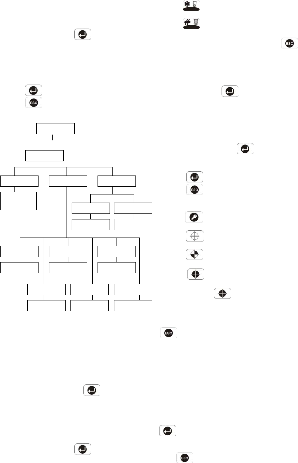
Scroll through the menu until ‘6-1 Status’ is displayed.
The current setting will also be displayed.
To change the setting press .
Scroll through the available options, (Off,
Selected-Users and All-Users), until the required
setting is displayed.
Press to save and exit, or
Press to exit without saving.
SELECTED-USERS SETUP
This allows controls over which users the Latch Key
facility operates with when set to ‘Selected-Users’.
Default setting: OFF
Scroll through the menu until ‘6-2 SELECTED USER
SETUP’ is displayed and press .
Scroll through the menu until the required user number
(1-6) to be configured is displayed. The current status
will also be displayed.
To change the setting press .
Press to enable the Latch-Key for the user, or
Press to disable the Latch-Key for the user.
After configuring all Users as required press to
return to the top level Latch Key Setup menu.
TELEPHONE NUMBERS
Scroll through the menu until ‘6-3 PHONE NUMBERS’
is displayed and press .
Scroll through the menu until the required telephone
number (1-2) is displayed. The current setting will
also be displayed.
To change the number press .
Enter the new telephone number (32 digits max).
Press to save and exit, or
Press to exit without saving.
Notes:
Press to insert a 3.6s pause in the dialing
sequence.
Press to move the cursor left.
Press to move the cursor right.
Press to delete the character under the
cursor.
Press and hold to erase the entire phone
number.
After programming all required phone numbers press
to return to the top level Latch Key Setup
menu.
HOME CONTROL SETUP
This controls the Everspring Home Automation
Receiver (e.g. BH002, BH003, BH004 & BH006) for a
maximum of 8 pcs.
Scroll through the top level programming menu until ‘7.
HOME CONTROL SETUP’ is displayed and press
.
Note: After completing the Home Control Setup
press to return to the top level programming
menu. 31
6. LATCH KEY
SETUP
Program Mode Code
6-2 SELECTED
USER SETUP
6-1 Status
xxx
OFF
Selected-Users
All-Users
6-3 PHONE
NUMBERS
Enter Phone No:
Enter Phone No:
Phone No. 2
xxxxxxxxxxxxxxxxx
Phone No. 1
xxxxxxxxxxxxxxxxx
Select
ON
->
*
OFF
->
#
User 3 Status
xxx
Select
ON
->
*
OFF
->
#
User 1 Status
xxx
User 5 Status
xxx
User 4 Status
xxx
Select
ON
->
*
OFF
->
#
User 2 Status
xxx
Select
ON
->
*
OFF
->
#
Select
ON
->
*
OFF
->
#
User 6 Status
xxx
Select
ON
->
*
OFF
->
#
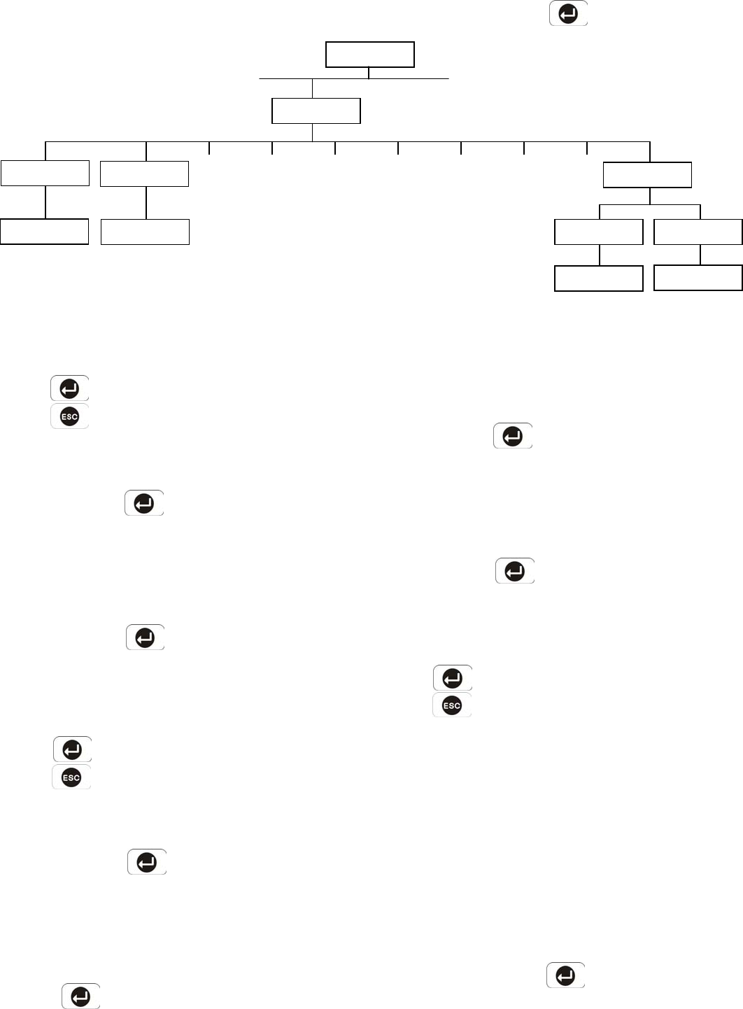
HOME AUTOMATION CONTROLLER HOUSE CODE
Default setting: A
Scroll through the menu until ‘7-1 Set House Code’ is
displayed. The current settings will also be displayed.
To change the settings press .
Scroll through the available options, (A~P), until
the required setting is displayed.
Press to save and exit, or
Press to exit without saving.
UNIT 1 SETUP
Scroll through the menu until ‘7-2 UNIT1 SETUP’ is
displayed and press .
Unit Code
Default setting: 01
Scroll through the menu until ‘:1 Unit Code’ is
displayed and press .
Enter the unit code (1-16) that your home automation
receiver has.
Press to save and exit, or
Press to exit without saving.
UNIT 2 SETUP
Scroll through the menu until ‘7-3 UNIT2 SETUP’ is
displayed and press
Unit Code
Default setting: 02
Scroll through the menu until ‘:1 Unit Code’ is displayed
and press .
32
Enter the unit code (1-16) that your home
automation receiver has.
UNIT 3 SETUP
Scroll through the menu until ‘7-4 UNIT3 SETUP’ is
displayed and press .
Unit code
Default setting: 03
Scroll through the menu until ‘:1 Unit Code’ is
displayed and press .
Enter the unit code (1-16) that your home
automation receiver has.
Press to save and exit, or
Press to exit without saving.
Note: Use the same method as mentioned above for
setting the unit 4-8 of home automation receiver.
ALARM TRIGGER
Default setting: OFF
Scroll through the menu until ‘7-10 BY ALARM
TRIGGER’ is displayed. The current setting will also be
displayed.
To change the setting press .
On/Off Status
Default setting: OFF
PROGRAM MODE
Code:
7. HOME CONTROL
SETUP
7-1 Set House
Code: xx
House Code: xx
7-2 UNIT1 SETUP
:1 Unit Code: xx
Unit 2 Unit 3 Unit 4 Unit 5 Unit 6 Unit 7 Unit 8
7-10 BY ALARM
TRIGGER XXX XXX
:10-2 Active Time
Enter (30
-
250s)
: 10-1 Status
xxx
Select
ON
->
*
OFF
->
#
Enter (10-250s)
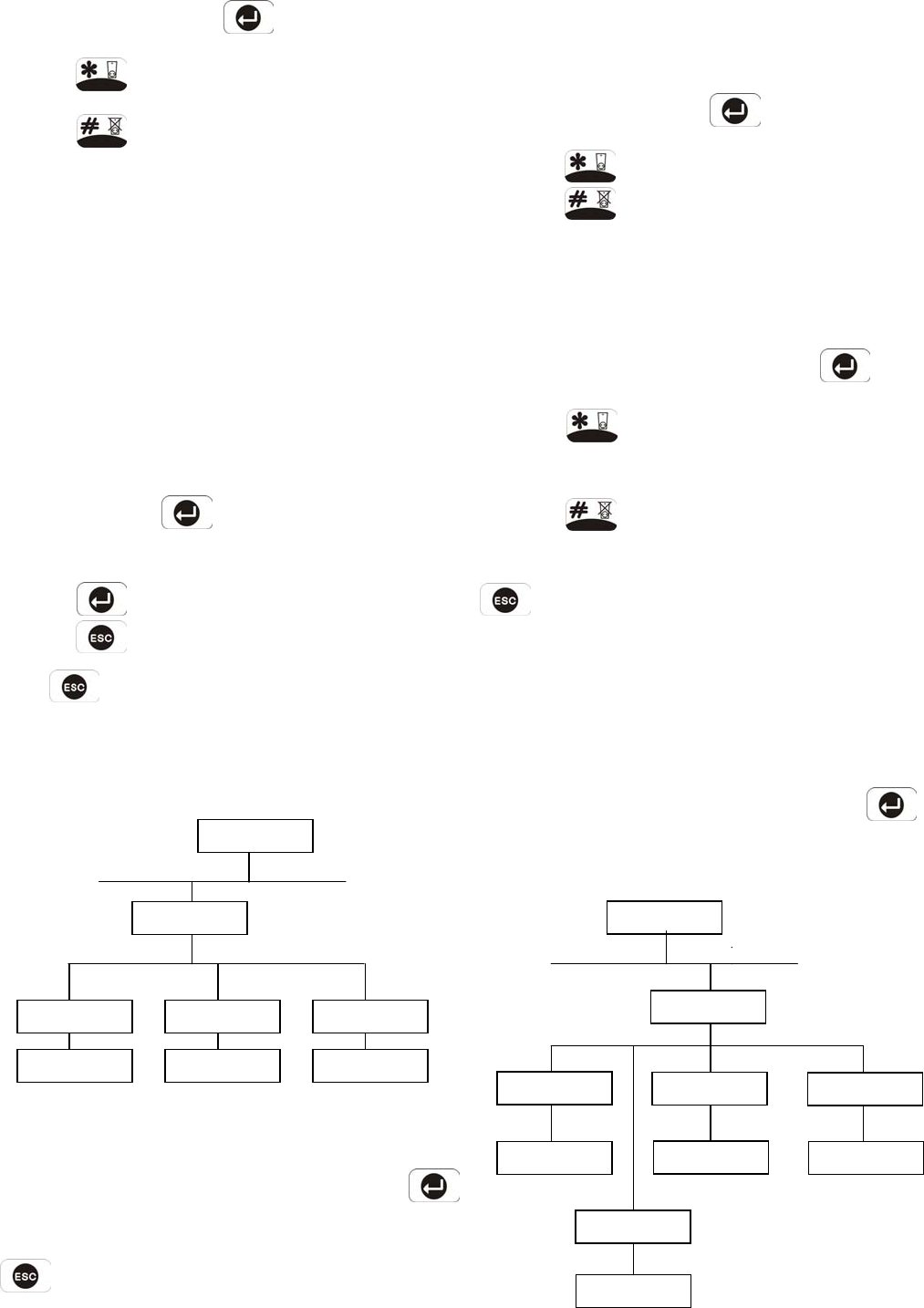
Scroll through the menu until ‘:10-1 Status’ is
displayed. The current setting will also be displayed.
To change the setting press .
Press to enable the home automation
receiver, or
Press to disable the home automation
receiver.
Active Time
This controls the illuminating duration of all the lighting
units connected to BH004/006 when the on/off status is
set for “ON”. After the elapse of pre-set illuminating
duration (30-250s variable), the lighting units will be off
automatically.
Default setting: 30 seconds
Scroll through the menu until ‘:10-2 Active Time’ is
displayed and press .
Enter the required active duration (30 to 250s).
Press to save and exit, or
Press to exit without saving.
Press to return to top level programming
mode.
ANSWER PHONE SETUP
Scroll through the programming menu until ’8.
ANSWER PHONE SETUP’ is displayed and press
Note: After completing the Answer Phone Setup press
to return to the top level programming menu.
ON/OFF STATUS
Default setting: OFF
Scroll through the menu until ’8-1 Status’ is displayed.
The current setting will also be displayed.
To change the setting press .
Press to enable the Answer-Phone, or
Press to disable the Answer-Phone.
RECORD GREETING
Scroll through the menu until ’8-2 Record Greeting’
is displayed.
To record a new greeting message press .
Press to start the voice recorder, (max.
duration: 12s). Once completed the recording will
automatically be played back, or
Press to exit without changing
Note: After recording the greeting message, press
to stop the recorder and cancel any remaining
message time.
REPLAY GREETING
Scroll through the menu until ’8-3 Replay Greeting’ is
displayed.
To replay the recorded greeting message press .
DIGITAL DIALER SETUP
33
Select
ON
->
*
OFF
->
#
8-1 Status
OFF
8. ANSWER PHONE
SETUP
PROGRAM MODE
Code:
8-2 Record
Greeting
8-3 Replay
Greeting
Start…
YES
->
*
NO
->
#
Playing …
PROGRAM MODE
Code:
9. DIGITAL
DIALER SETUP
9-1 Phone No:
xxxxxxxxx
Enter Phone No:
xxxxxxxxx
9-2 Unit ID No:
xxxx
Enter Unit ID:
xxxx
9-3 Call
Attempts:
Enter 1-5:
x
-
9-4 Open/Close
By User:
Select
ON
->
*
OFF
->
#
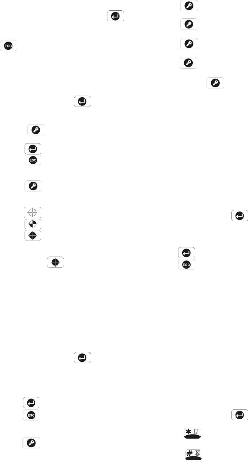
Scroll through the programming menu until ‘9. DIGITAL
DIALER SETUP’ is displayed and press .
Note: After completing the Digital Dialer Setup press
o to return to the top level programming menu.
PHONE NUMBER
Scroll through the menu until ‘9-1 Phone No:’ is
displayed. The current setting will also be display.
To change the setting press .
Enter the phone number (32 digits max. ranging from
0~9, *, #, ) that Central Monitoring station has.
Press to save and exit, or
Press to exit without saving.
Notes:
Press to insert a 3.6s pause in the dialing
sequence.
Press to move the cursor left.
Press to move the cursor right.
Press to delete the character under the
cursor.
Press and hold to erase the entire phone
number.
UNIT ID NUMBER
This helps central monitoring station set an ID number
for the user whose system is connected to their center.
Scroll through the menu until ‘9-2 Unit ID No:’ is
displayed. The current setting will also be displayed.
To change the setting press .
Enter the ID number (4 digits max. ranging from 0-9,
B,C,D,E, F)
Press to save and exit, or
Press to exit without saving.
Notes:
Press and then 1, a ‘B’ will be presented.
34
Press and then 2, a ‘C’ will be presented.
Press and then 3, a ‘D’ will be presented.
Press and then 4, an ‘E’ will be presented.
Press and then 5, a ‘F’ will be presented.
When pressing for 3 seconds, no further
input is made, it will be regarded as void input.
CALL ATTEMPTS
This sets the maximum number of times that the dialer
will attempt to contact the central monitoring station.
If the dialer contacts to the central monitoring station
once successfully, it will stop dialing.
Default setting: 3
Scroll through the menu until ‘9-3 Call Attempts’ is
displayed. The current setting will also be displayed.
To change the setting press .
Enter the required number (1-5).
Press to save and exit, or
Press to exit without saving.
OPEN/CLOSE BY USER
This determines when user makes a selection for
disarming (Open) or arming (Close) the system, an
event code 401 is needed to be sent to the central
monitoring station. When setting to ‘On’, an event
code 401 will be emitted, setting to ‘Off’, an event code
401 won’t be emitted.
Default setting: Off
Scroll through the menu until ‘9-4 Open/Close By
User’ is displayed. The current setting will also be
displayed.
To change the setting press .
Press to commence sending the event
code.
Press to commence not sending the event
code.

Press to return to top level Digital Dialer Setup
menu.
35
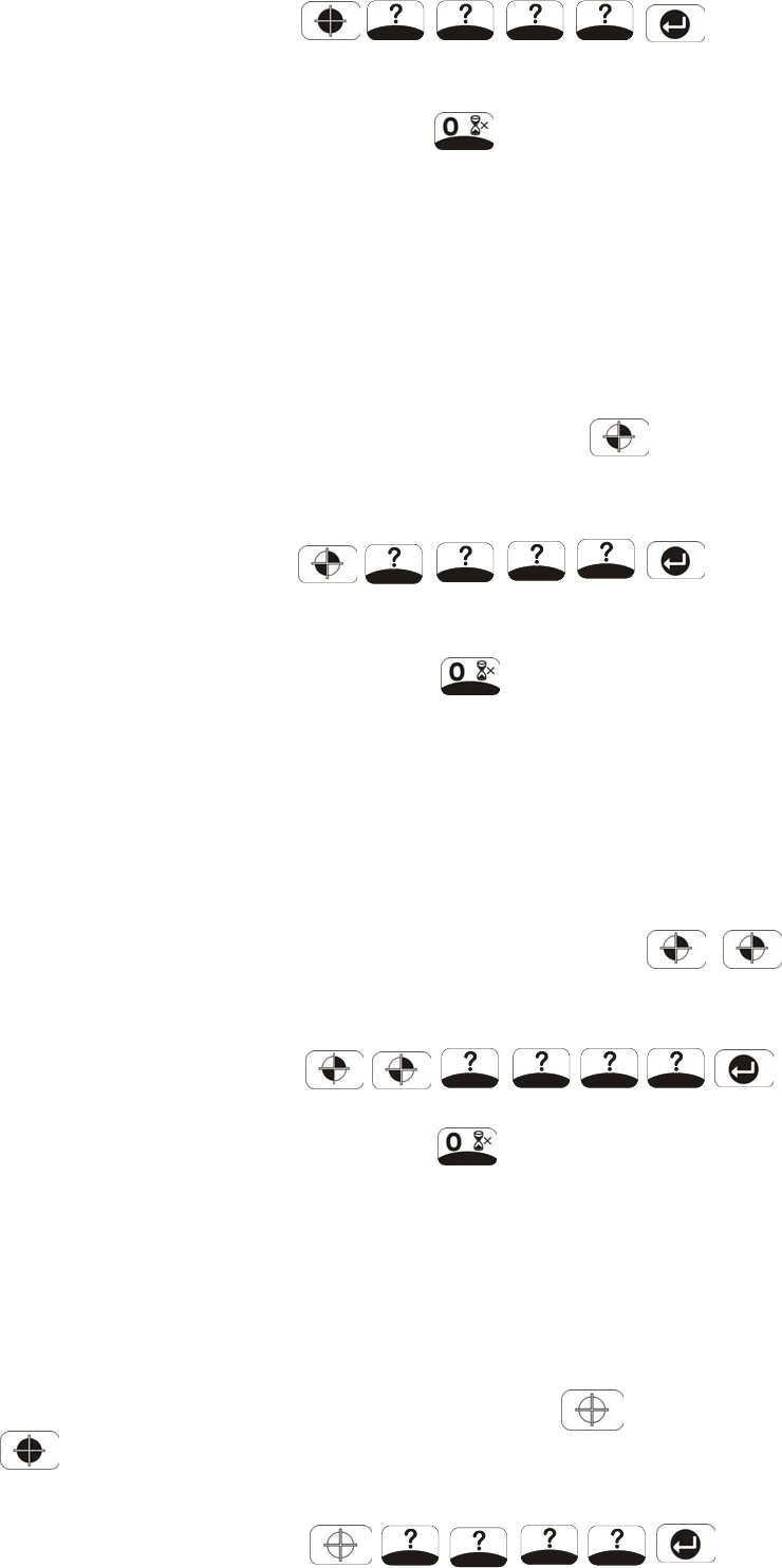
OPERATING INSTRUCTIONS
When leaving the premises, the system must be Armed.
However, before doing so, check that all windows are
closed and locked, all protected doors are closed and
PIR Detectors are not obstructed. Ensure that pets
are restricted to areas not protected by PIR Detectors.
The system has three arming modes, ARM, Part-Arm 1
and Part-Arm 2. The Part-Arm modes allow for
selected zones to be left in a Disarmed state while the
reminder of the system is Armed.
When the system is Armed (in any mode) the Control
Panel will display the arming mode and the status of the
Latch Key for a few seconds. If enabled, the system
Exit-Delay will start and be counted down on the display.
As the Exit-Delay expires the Control Panel will beep,
with the beep rate increasing in steps as the delay
expires. At the end of the Exit-Delay all active zones
be Armed. By this time the user must have left the
property and closed the final exit door.
If while the system is armed a detector on an active
zone is triggered, if enabled, the programmed
Entry-delay for that zone will start and be counted down
on the display. As the Entry-Delay expires the Control
Panel will beep, with the beep rate increasing in steps
as the delay expires. If the system has not been
disarmed when the Entry-Delay expires an alarm will
occur. If however, the Entry-Delay for the triggered
zone has been disabled an alarm will occur
immediately.
At the end of the programmed alarm duration the Siren
and Control Panel alarms will stop and the system will
automatically re-Arm.
ARM
The system can be set in ARM mode using either the
Remote Control or the Control Panel as follows:
Remote Control:
Press the ‘ARM’ button, ..
Control Panel:
Press the Arm button followed by the User
Password and then the Enter button:
36
User Password
By pressing , the programmed exit delay
will be overrided to 5 seconds.
PART-ARM 1
The system can be set in PART-Arm 1 mode using
either the Remote Control or the Control Panel as
follows:
Remote Control:
Press the ‘PART-ARM’ button, .
Control Panel:
User Password
By pressing , the programmed exit delay will
be overrided to 5 seconds.
PART-ARM 2
The system can be set in Part-Arm 2 mode using either
the Remote Control or the Control Panel as follows:
Remote Control:
Press the ‘PART-ARM’ button twice, , .
Control Panel:
User Password
By pressing , the programmed exit delay will
be overrided to 5 seconds.
DISARM
The system can be Disarmed using either the Remote
Control or the Control Panel as follows:
Remote Control:
Press the ‘DISARM’ button, .
Control Panel:
User Password
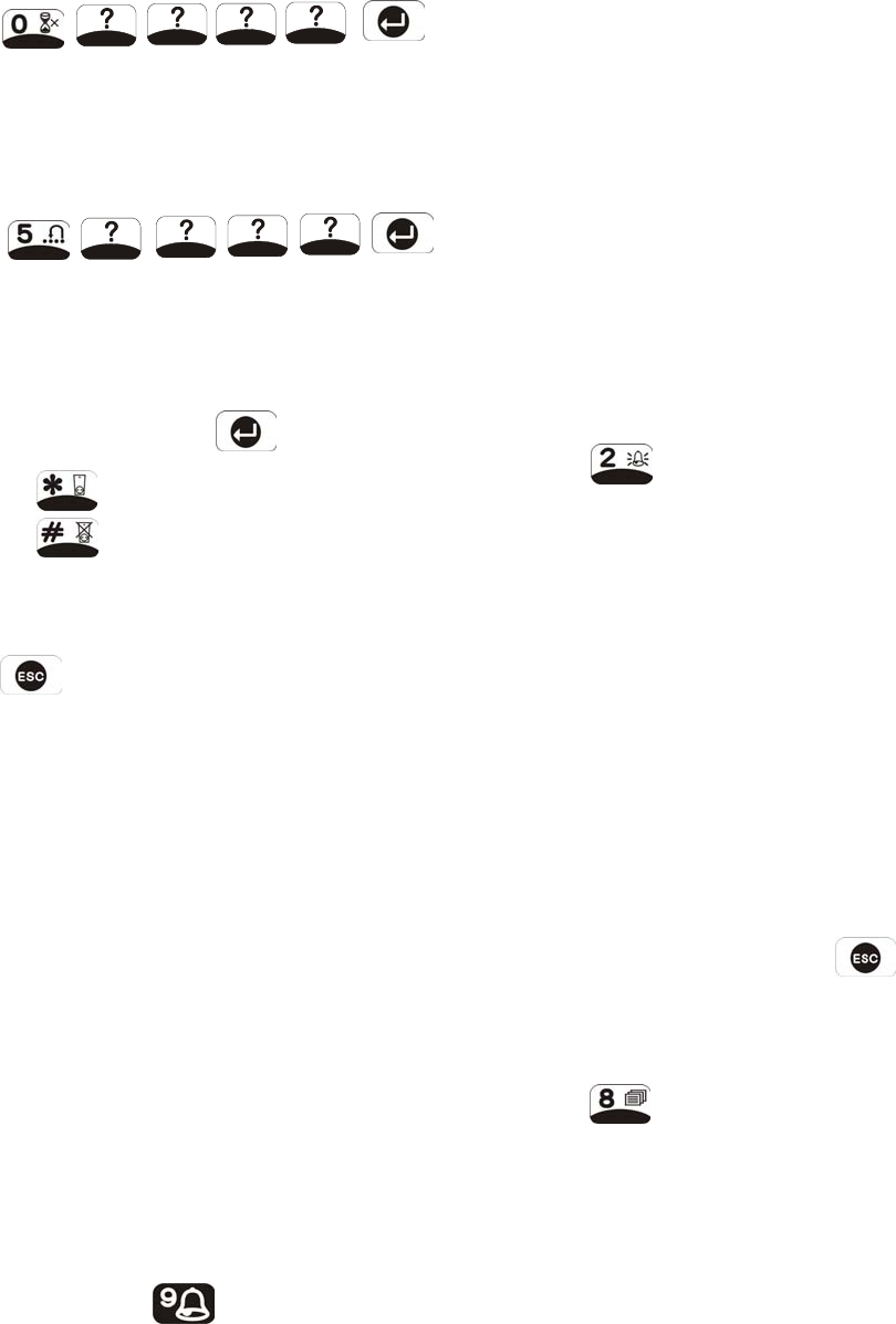
If the system is disarmed and the ‘ALARM MEM’ LED is
flashing with the panel beeping every few seconds, this
indicates that an alarm condition has occurred. Use
the Event Log to find out and make a note of where the
alarm occurred to assist in tracing the cause of the
alarm.
QUICK SET
To operate the quick set function and fully arm the
system in 5s, overriding the programmed exit delay.
Press
User Password
OMIT ZONE
To omit a zone from the next armed session:
Press
User Password
Scroll through the menu until the required zone is
displayed. The current setting will also be displayed.
To change the setting press .
Press to omit the zone, (i.e. zone omit ON).
Press to re-enable the zone, (i.e. zone omit
OFF).
After configuring zones to be omitted as required
Press to return to Standby mode.
Note: Omitting a zone will only affect the next armed
session. When the system is disarmed the omitted
zones will be re-enabled ready for the next armed
session.
PANIC ALARM
A full Alarm condition can be immediately initiated
at any time (whether the system is Armed or Disarmed)
in the event of threat or danger by activating a Panic
switch on either the Remote Control or the Control
Panel.
Remote Control:
Slide the Panic switch upwards.
Control Panel:
Press and hold the button for approximately
3 seconds.
The alarm will continue either for the alarm duration
when the system will automatically reset or until the
system is disarmed.
TAMPER
If the battery cover of any device is removed or if the
Siren or Control Panel are removed from the wall then
a Full Alarm condition will be initiated even if the
system is Disarmed. The alarm condition will continue
either for the alarm duration when the system will
automatically reset or until the system is Disarmed.
The ‘ALARM MEM’ LED on the Control Panel will flash
and the panel will beep every few seconds to indicate
an alarm has occurred.
Note: The Tamper protection facility on the Siren
operates independently. If the Tamper on the Siren is
activated this will not be indicated at the Control Panel.
CHIME
The Chime facility can only be operated with the
system in Standby mode.
Press to toggle the Chime facility between ON
and OFF.
Note: If the Chime is ON and the system is then armed
the Chime will remain ON after the system is disarmed.
EVENT-LOG
The Event Log will store the last 50 system Arm, disarm,
alarm and detector Low Battery events. The Event
Log will record the time, date and details for each event.
If when the system is disarmed the “ALARM MEM’ LED
is flashing and the panel beeps every 10s, this
indicates that an alarm has occurred. To cancel the
LED and stop the beeping you must access the event
log or press to eliminate the flashing ‘ALARM
MEM’ LED and the beeping as well.
To access the Event Log, (with the system in Standby):
Press .
The Event-Log will automatically start scrolling through
and displaying the event data starting with the most
recent event. The data for each event is shown on
two screens, each screen will be displayed for 5
37
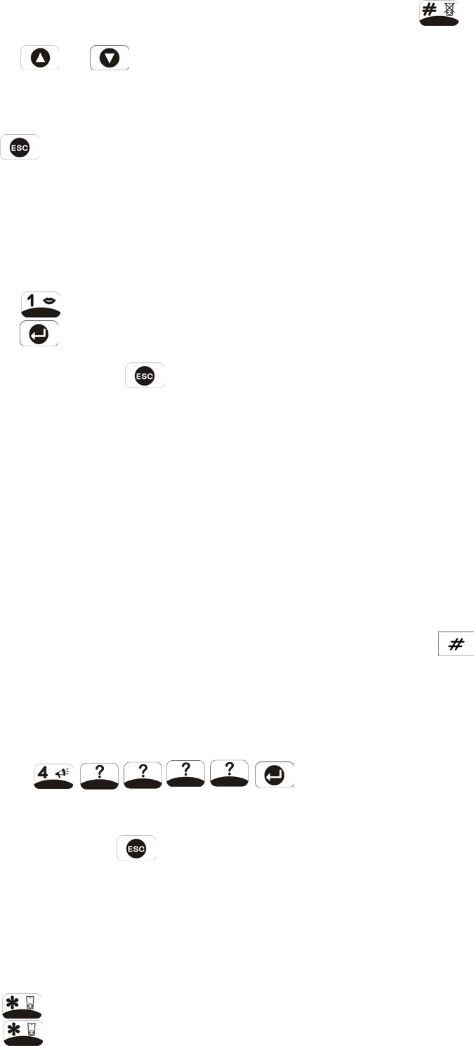
seconds before moving on to the next screen and then
the next event.
Use the and buttons to manually scroll
through the event log to the required position as
necessary.
Press to return to standby.
VOICE MEMO
To record a message, (max. duration 30s), at the
Control Panel using the Voice Memo facility, proceed as
follows:
Press
Press to start recording
While recording, press to stop the recorder
and skip the remaining message time.
If there are already 6 messages recorded it will not be
possible to record a voice-memo message until a
message has been deleted.
The Voice Memo message may be accessed either at
the Control Panel (see Replay Messages) or via the
Remote System Control facility.
REPLAY MESSAGES
If the ‘MESSAGE’ LED is illuminated, this indicates
that either a new Answer-Phone or Voice-Memo
message has been recorded and has not been read.
The recorded messages may be accessed at the
Control Panel as follows:
Press ,
User Password
Messages are replayed in order starting with the
most recent. Press to skip to the end of the
message.
At the end of each message there will the option of
deleting the message just heard.
To delete the message
Press to delete the message
Press to re-confirm and actually delete the
message
38
Note: Press at either stage to cancel delete
and move on to the next message.
After all messages have been replayed the system will
automatically return to Standby Mode.
REMOTE SYSTEM CONTROL
If the Remote System Control facility is enabled, the
Control Panel will answer the call after the set number
of rings and emit three beeps on the phone line to
prompt for a User Password to be entered using the
telephone keypad.
A valid User Password will be acknowledged with one
long beep. An incorrect code will be acknowledged by
two short beeps.
If the User Password is not entered within 30s or is
entered incorrectly three times then the Control Panel
will automatically hang-up the line.
Note: If the internal Answer-Phone is also enabled and
there is space for a new message then the call will be
answered with the Answer-Phone greeting message.
The User Password should be entered during the
greeting message, otherwise the answer phone
message recorder will be activated.
By pressing the button on the telephone keypad
within 30 seconds, the Control Panel will automatically
hang-up the line.
Use with an External Answer-Phone:
If the Remote System Control is to be used in
conjunction with an external Answer-Phone then
1. The internal Answer-Phone must be disabled.
2. The number of ‘ring to answer’ for the Control
Panel must be greater than that of the External
Answer-Phone, otherwise the Control Panel will
always pickup the call before the Answer-Phone.
To access the Remote System Control facility the
Control Panel has a ‘double dial-in’ feature to enable
the Control Panel to pick-up the phone call before the
external Answer-Phone cuts in. The ‘double dial-in’
procedure is as follows:
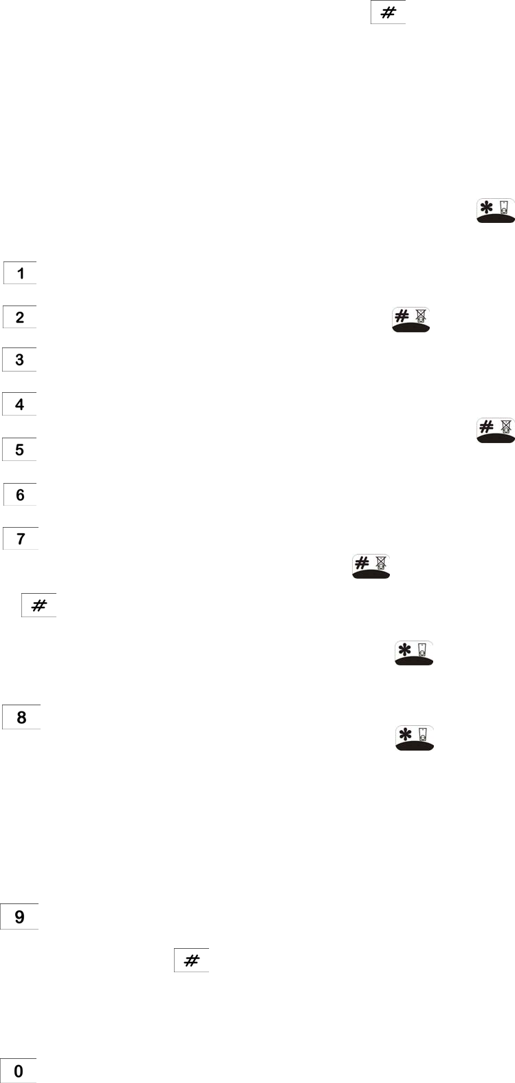
1. Dial up the system and hang up after two rings.
2. Redial up the system within 20s as maximum (5s
as minimum), the system will pickup the phone
after 1 ring.
3. Enter the User Password as normal.
The following functions may be access via the remote.
The system will acknowledge each signal with a single
long beep.
Press to initiate ARM.
Press to initiate Part-Arm 1.
Press to initiate Part-Arm 2.
Press to Disarm the system.
Press to turn the Siren OFF
.
Press to turn the Siren ON.
Press to Listen-In via the Control Panel
Microphone.
Press to stop Listen-In
Note: Listen-in will be automatically cancelled after
5 minutes if not cancelled manually.
Press to interrogate the system status. The
status tone will be repeated at 2s intervals for 15s.
One beep ARM
Two beeps Part-Arm (1 or 2)
Three beeps Alarm triggered
Four beeps Fire triggered
One long beep Disarmed
Press to replay Answer-Phone messages.
While replaying a message, press for 2 seconds
to skip to the end of the message and hear the next
message.
Press to delete all Answer Phone messages.
Press to end the session and hang up the
Control Panel line.
CONNECTION TO HOME AUTOMATION
MODULES
Under the disarm mode, the on/off power of a series of
home automation receiver modules can be controlled
by the Control Panel as follows:
1. BH002/003: Press on the Control Panel’s
keypad and then key in the unit code (numbered
1-8) of home automation receiver modules to turn
on the power manually.
Press on the Control Panel’s keypad and
then key in the unit code (numbered 1-8) of home
automation receiver modules to turn off the power
manually.
2. BH004/006: Press on the Control Panel’s
keypad and then key in the unit code (numbered
1-8) of home automation receiver modules to turn
on and turn off the power manually.
Note: To turn on and turn off the lighting
fixture connected to BH004/006, simply using
as a toggle switch.
Note: Prior to adjusting the dimmer brightness, the
prerequisite is to turn on the lighting fixture.
Press on the Control Panel’s keypad and
then key in the unit code (numbered 1-8) of home
automation receiver modules to start dimmer cycle.
Press on the Control Panel’s keypad and
then key in the unit code (numbered 1-8) of home
automation receiver modules to select the dimmer
brightness you desire.
BATTERY MONITORING
All system devices continuously monitor their battery
condition. The Control Panel also monitors the battery
condition of all PIR and Magnetic detectors. If the
battery level of any device drops below acceptable
levels then its low battery indication will be activated.
In addition if any PIR or Magnetic Contact detector has
a low battery status it will be recorded by the Control
Panel and a message stored in the event log.
39

In the event of AC adaptor being disconnected from the
Control Panel, the Control Panel by consuming the DC
rechargeable battery can sustain 2 days of normal
operation (under standby mode) . However, the battery
for that device should be replaced as soon as possible.
Note: Before removing the battery cover on any device
to replace the battery ensure that the system is put into
Test mode to avoid initiating a Full Alarm condition.
The low battery indication for each system component
is as follows:
Control Panel
During a period of mains supply interruption the Control
Panel will be powered by the rechargeable backup
batteries. Under normal battery conditions the Power
LED on the panel will flash at 1s intervals. However,
under low battery conditions the Power LED will flash at
3s intervals.
Remote Control
When the Remote Control is operated under low
battery conditions the transmit LED will continue to
flash after the button has been released.
Under normal battery conditions the LED will extinguish
when the button is released.
PIR Detectors
Under low battery conditions the LED behind the
detector lens will flash when movement is detected to
indicate that the battery needs to be replaced.
Under normal battery conditions the LED does not
illuminate unless the PIR detector is in Walk Test mode.
Magnetic Contact Detectors
Under low battery conditions, when the Detector is
activated the transmit LED will be illuminated for
approximately 1s as the door/window is opened.
Under normal battery conditions the LED will not
illuminate as the Detector is operated, (unless the
Detector is in Test Mode with the battery cover
removed).
40
MAINTENANCE
Your Alarm System requires very little maintenance.
However, a few simple tasks will ensure its continued
reliability and operation.
CONTROL PANEL
The rechargeable batteries have a typical life of 3-4
years and need no maintenance during this period,
provided they are kept charged. The batteries will be
damaged if they are stored in a discharged state for
long periods.
DETECTORS AND REMOTE CONTROL
The Detectors require very little maintenance. The
batteries should be replaced once a year or when a low
battery status is indicated.
IMPORTANT: Should you, for any reason, have to
completely power-down the system (e.g. to move the
system to a new premises) first put the system into Test
mode before removing the Control Panel cover and
disconnecting the power supply and backup batteries.
BATTERIES
Before removing the battery cover on any device to
replace the battery, ensure that the system is put into
Test mode to avoid initiating an Alarm.
The specifications for replacement batteries are as
follows:
Remote Controls 1 x 3V CR2032 Lithium Cells
(or equivalent)
Magnetic Contact
Detectors
2 x 3V CR2032 Lithium Cells
(or equivalent)
PIR Detectors 1 x 9V PP3 Alkaline
Note: Where applicable only fit PP3 Alkaline type
batteries. Rechargeable batteries should NOT be
fitted.
At the end of their useful life the batteries should be
disposed of via a suitable Recycling Centre. Do not
dispose of with your normal household waste. DO
NOT BURN.
The Rechargeable batteries contain Sulphuric Acid –
DO NOT ATTEMPT TO OPEN THE CASING.
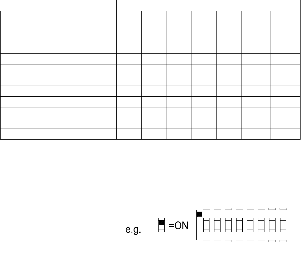
ALARM RECORD
Complete the following information during installation for future reference when adding to your system and to assist
Trouble Shooting.
Zone Settings
Zone Detector
Type(s)
Location Type Final
Exit
Entry
Delay
Chime Arm Part-Arm
1
Part-Arm
2
1
2
3
4
5
6
7
8
9
10
You may make a note of your User Password and Installer Password below.
System Password
User 1: _______________________ User 2: _______________________ User 3: _______________________
User 4: _______________________ User 5: _______________________ User 6: _______________________
Master User: ________________________________________
System House Code
Use the diagram to record your House Code
Voice Dialer Phone Numbers
Phone No. 1: ______________________________ Phone No. 2: ______________________________
Phone No. 3: ______________________________ Phone No. 4: ______________________________
Latch-Key Phone Numbers
Phone No. 1: ______________________________ Phone No. 2: _______________________________
Digital Dialer Phone Numbers
Phone No. ________________________________ System ID No. _______________________________
This information is confidential and should be kept in a safe location.
41
1 32 54
ON
76 8
ECE

TROUBLE SHOOTING
Control Unit not working – Power LED OFF or
flashing
1. Mains power failure – check if other electrical
circuits are operable.
2. Check that mains adaptor is plugged in and
socket is switched ON.
3. Check mains fuse in Plug has not blown.
4. Check that DC jack plug from mains adaptor is
connected in Control Panel.
5. Check fuse/MCB in Consumer Unit on the
circuit serving the Control Panel.
Note: Before replacing any fuses or resetting
the MCB, the cause of the failure should be
investigated and rectified.
Control Unit not accepting User Password
1. Pause between key depressions too long. Do
not pause for more than 5 seconds between
pressing keys.
2. Incorrect code entered.
3. Reset to factory defaults and reprogram system.
Control Unit not responding to detectors
1. Ensure that the ‘House Code’ is correctly set.
2. Ensure detector is within effective radio range
of Control Panel and equipment is not mounted
close to metal objects.
3. Detector battery low – replace battery.
Voice-Dialer not responding to Alarm
1. Telephone line not connected or faulty – check
phone line with another phone
2. Dial Method incorrectly programmed
3. Incorrect phone numbers programmed
4. Phone numbers disabled in dialing sequence
5. Alarm messages not recorded
42
Answer-Phone not responding or recording
messages
1. Telephone line not connected or faulty – check
phone line with another phone
2. Dial Method incorrectly programmed
3. Answer-Phone disabled
4. No space in message store, 6 messages
already recorded.
Cannot record Voice-Memo message at Control
Panel
1. No space in message store, 6 messages
already recorded.
Control Unit not contacting central monitoring
station service on alarm
1. Telephone line not connected or faulty – check
phone line with another phone.
2. Dial Method incorrectly programmed.
3. Incorrect phone number for central monitoring
station service programmed
4. Incorrect system ID number for central
monitoring station service programmed.
5. Central monitoring station service not
commissioned or signed up.
Control Unit not responding to Remote Phone
Access
1. Telephone line not connected or faulty – check
phone line with another phone
2. Remote Access disabled
3. Incorrect User Password entered
Latch Key not responding when system
disarmed
1. Telephone line not connected or faulty – check
phone line with another phone
2. Dial Method incorrectly programmed
3. Latch-Key disabled
4. Latch Key set to Selected-Users and not
enabled for User that is Disarming the system
5. No Latch-Key phone numbers programmed

Full alarm condition occurs when system has
not been triggered by an intruder or is disarmed
1. Tamper switch activation
- check all detector battery covers to ensure
correctly fitted
- check Control Panel and Siren are securely
mounted to the wall and tamper switch is
closed
2. Panic alarm operated from a Remote Control or
Keypad
3. Jamming detection circuit operated
LED on remote control not illuminating, or is
dim when unit is operated
1. Ensure battery is connected with correct polarity
2. Ensure battery connections are good
3. Replace battery
PIR Detector false alarming
1. Ensure that the detector is not pointing at a
source of heat or a moving object
2. Ensure that the detector is not mounted above a
radiator or heater
3. Ensure that the detector is not facing a window
or in direct sunlight
4. Ensure that the detector is not in a draughty
area
5. Sensitivity detection set too high –reset to low
sensitivity detection
PIR Detector not detecting a person’s movement
1. Check battery connections are good.
2. Sensitivity detection set too low– reset to high
sensitivity detection.
3. Check that the detector is correctly set up.
4. Ensure DIP switches 1-4 of SW3 are correctly
set.
5. Ensure that detector is mounted the correct way
up.
(i.e. with detection window at the bottom)
6. Ensure that the detector is mounted at the
correct height, (i.e. 2-2.5m).
7. Allow up to three minutes for detector to
stabilize.
PIR Detector LED flashes on detection of
movement, (device in normal operation mode)
1. Low battery – replace battery.
Magnetic Contact Detector not working
1. Ensure batteries are connected with correct
polarity.
2. Ensure battery connections are good.
3. Ensure ‘House Code’ is correctly set.
4. Ensure DIP switches 9, 10 and 11 are set
correctly.
5. If no external contacts are connected ensure
jumper link fitted.
6. If external contacts are connected
a. Ensure jumper link removed
b. Check that all contacts are closed.
c. Check all contacts are wired in series.
Magnetic Contact Detector false alarming
1. Ensure that gap between magnet and detector
is less than 10mm.
2. Tamper switch below battery cover not
depressed – check battery cover is fitted
correctly and that fixing lugs are not broken.
LED on Magnetic Contact Detector illuminating
when door or window is opened.
1. Low battery – replace batteries.
DIGITAL DIALER TRANSMISSION
PROTOCOL
Contact ID Event Codes
Definition Code
Fire/Smoke Alarm 110
Panic Alarm 120
Intruder Alarm 130
24hr Intruder 133
System Tamper 137
AC Failure 301
System Low Battery 302
Sensor Tamper 383
Sensor Low Battery 384
Cancel/Abort Alarm 406
System Test 601
Open/Close by User 401
INH302WEVSP0E2A 43
FEDERAL COMMUNICATION COMMISSION INTERFERENCE STATEMENT
This equipment has been tested and found to comply with the limits for a Class B digital device, pursuant to Part 15
of the FCC Rules. These limits are designed to provide reasonable protection against harmful interference in a
residential installation. This equipment generates, uses and can radiate radio frequency energy and, if not installed
and used in accordance with the instructions, may cause harmful interference to radio communications. However,
there is no guarantee that interference will not occur in a particular installation. If this equipment does cause
harmful interference to radio or television reception, which can be determined by turning the equipment off and on,
the user is encouraged to try to correct the interference by one of the following measures:
- Reorient or relocate the receiving antenna.
- Increase the separation between the equipment and receiver.
- Connect the equipment into an outlet on a circuit different from that to which the receiver is connected.
- Consult the dealer or an experienced radio/TV technician for help.
FCC Caution: Any changes or modifications not expressly approved by the party responsible for compliance could
void the user’s authority to operate this equipment.
This device complies with Part 15 of the FCC Rules. Operation is subject to the following two conditions: (1) This
device may not cause harmful interference, and (2) this device must accept any interference received, including
interference that may cause undesired operation.