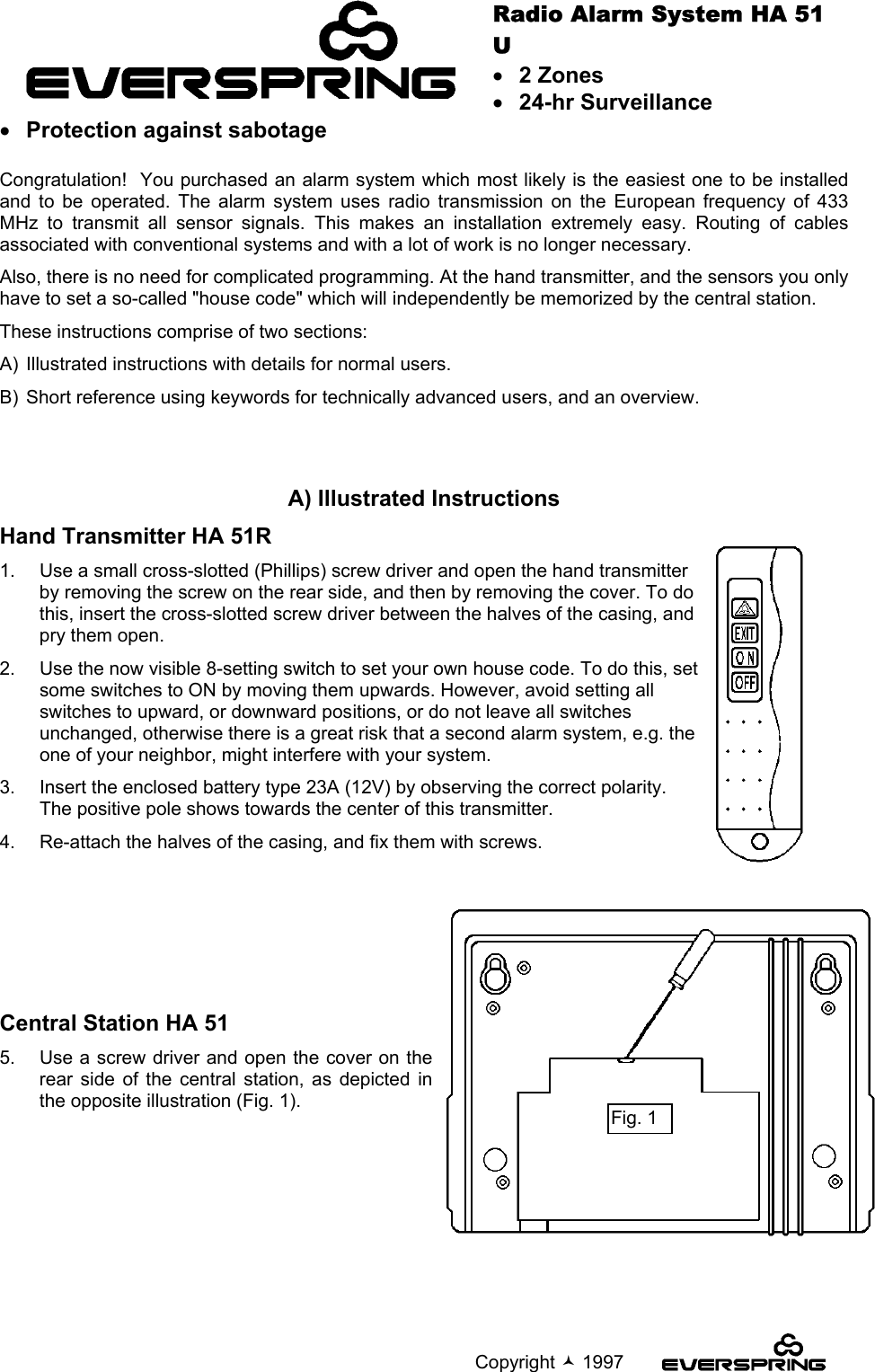
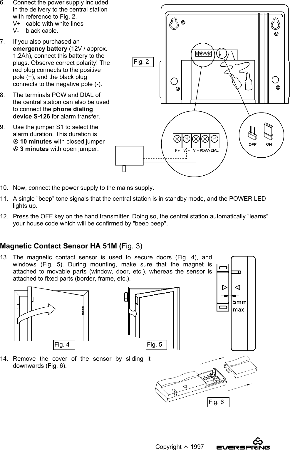
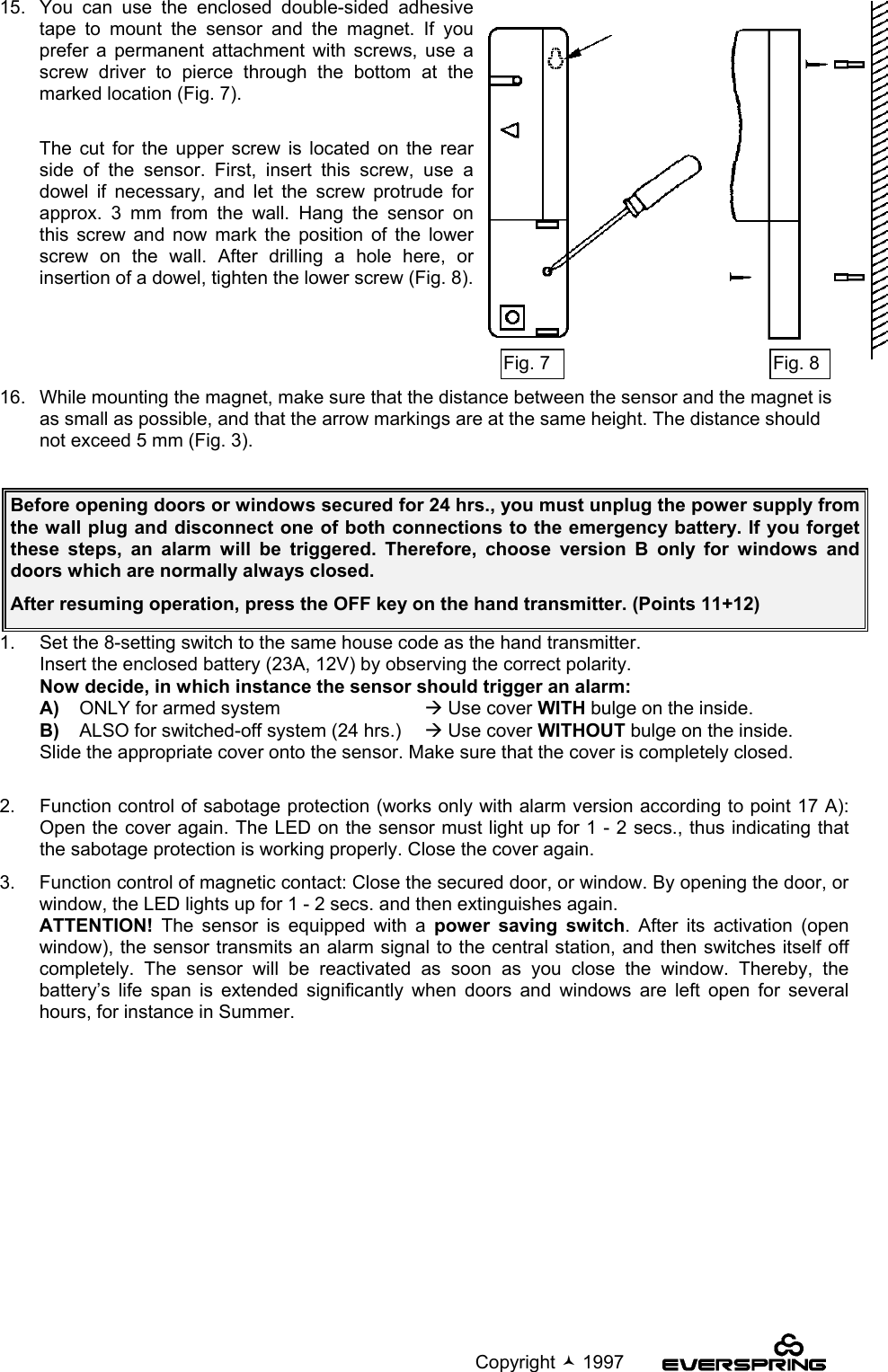
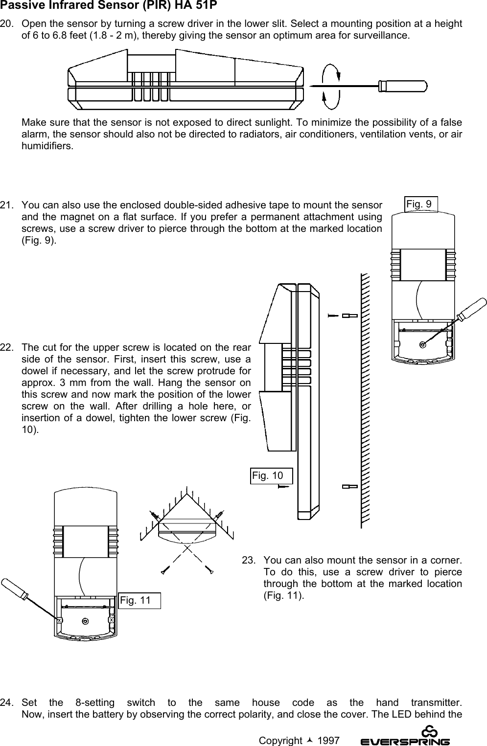
Everspring Industry Co HA51R Hand Held Transmitter User Manual HA51U

Everspring Industry Co Ltd Hand Held Transmitter HA51U

Users Manual

                                                                                            Copyright  1997Radio Alarm System HA 51U• 2 Zones• 24-hr Surveillance• Protection against sabotageCongratulation!  You purchased an alarm system which most likely is the easiest one to be installedand to be operated. The alarm system uses radio transmission on the European frequency of 433MHz to transmit all sensor signals. This makes an installation extremely easy. Routing of cablesassociated with conventional systems and with a lot of work is no longer necessary.Also, there is no need for complicated programming. At the hand transmitter, and the sensors you onlyhave to set a so-called "house code" which will independently be memorized by the central station.These instructions comprise of two sections:A)  Illustrated instructions with details for normal users.B)  Short reference using keywords for technically advanced users, and an overview.A) Illustrated InstructionsHand Transmitter HA 51R1.   Use a small cross-slotted (Phillips) screw driver and open the hand transmitterby removing the screw on the rear side, and then by removing the cover. To dothis, insert the cross-slotted screw driver between the halves of the casing, andpry them open.2.   Use the now visible 8-setting switch to set your own house code. To do this, setsome switches to ON by moving them upwards. However, avoid setting allswitches to upward, or downward positions, or do not leave all switchesunchanged, otherwise there is a great risk that a second alarm system, e.g. theone of your neighbor, might interfere with your system.3.   Insert the enclosed battery type 23A (12V) by observing the correct polarity.The positive pole shows towards the center of this transmitter.4.   Re-attach the halves of the casing, and fix them with screws.Central Station HA 515.   Use a screw driver and open the cover on therear side of the central station, as depicted inthe opposite illustration (Fig. 1).          Fig. 1
                                                                                            Copyright  19976.   Connect the power supply includedin the delivery to the central stationwith reference to Fig. 2,V+ cable with white linesV- black cable.7.   If you also purchased anemergency battery (12V / approx.1.2Ah), connect this battery to theplugs. Observe correct polarity! Thered plug connects to the positivepole (+), and the black plugconnects to the negative pole (-).8.   The terminals POW and DIAL ofthe central station can also be usedto connect the phone dialingdevice S-126 for alarm transfer.9.   Use the jumper S1 to select thealarm duration. This duration is! 10 minutes with closed jumper! 3 minutes with open jumper.10.   Now, connect the power supply to the mains supply.11.   A single "beep" tone signals that the central station is in standby mode, and the POWER LEDlights up.12.   Press the OFF key on the hand transmitter. Doing so, the central station automatically "learns"your house code which will be confirmed by "beep beep".Magnetic Contact Sensor HA 51M (Fig. 3)13.  The magnetic contact sensor is used to secure doors (Fig. 4), andwindows (Fig. 5). During mounting, make sure that the magnet isattached to movable parts (window, door, etc.), whereas the sensor isattached to fixed parts (border, frame, etc.).14. Remove the cover of the sensor by sliding itdownwards (Fig. 6).Fig. 2Fig. 4 Fig. 5Fig. 6
                                                                                            Copyright  199715.  You can use the enclosed double-sided adhesivetape to mount the sensor and the magnet. If youprefer a permanent attachment with screws, use ascrew driver to pierce through the bottom at themarked location (Fig. 7).  The cut for the upper screw is located on the rearside of the sensor. First, insert this screw, use adowel if necessary, and let the screw protrude forapprox. 3 mm from the wall. Hang the sensor onthis screw and now mark the position of the lowerscrew on the wall. After drilling a hole here, orinsertion of a dowel, tighten the lower screw (Fig. 8).16.   While mounting the magnet, make sure that the distance between the sensor and the magnet isas small as possible, and that the arrow markings are at the same height. The distance shouldnot exceed 5 mm (Fig. 3).1.   Set the 8-setting switch to the same house code as the hand transmitter.Insert the enclosed battery (23A, 12V) by observing the correct polarity.Now decide, in which instance the sensor should trigger an alarm:A)  ONLY for armed system Æ Use cover WITH bulge on the inside.   B)  ALSO for switched-off system (24 hrs.) Æ Use cover WITHOUT bulge on the inside.Slide the appropriate cover onto the sensor. Make sure that the cover is completely closed.  2.   Function control of sabotage protection (works only with alarm version according to point 17 A):Open the cover again. The LED on the sensor must light up for 1 - 2 secs., thus indicating thatthe sabotage protection is working properly. Close the cover again.3.   Function control of magnetic contact: Close the secured door, or window. By opening the door, orwindow, the LED lights up for 1 - 2 secs. and then extinguishes again.ATTENTION! The sensor is equipped with a power saving switch. After its activation (openwindow), the sensor transmits an alarm signal to the central station, and then switches itself offcompletely. The sensor will be reactivated as soon as you close the window. Thereby, thebattery’s life span is extended significantly when doors and windows are left open for severalhours, for instance in Summer.Before opening doors or windows secured for 24 hrs., you must unplug the power supply fromthe wall plug and disconnect one of both connections to the emergency battery. If you forgetthese steps, an alarm will be triggered. Therefore, choose version B only for windows anddoors which are normally always closed.After resuming operation, press the OFF key on the hand transmitter. (Points 11+12)Fig. 7 Fig. 8
                                                                                            Copyright  1997Passive Infrared Sensor (PIR) HA 51P20.   Open the sensor by turning a screw driver in the lower slit. Select a mounting position at a heightof 6 to 6.8 feet (1.8 - 2 m), thereby giving the sensor an optimum area for surveillance.Make sure that the sensor is not exposed to direct sunlight. To minimize the possibility of a falsealarm, the sensor should also not be directed to radiators, air conditioners, ventilation vents, or airhumidifiers.21.   You can also use the enclosed double-sided adhesive tape to mount the sensorand the magnet on a flat surface. If you prefer a permanent attachment usingscrews, use a screw driver to pierce through the bottom at the marked location(Fig. 9).   22.   The cut for the upper screw is located on the rearside of the sensor. First, insert this screw, use adowel if necessary, and let the screw protrude forapprox. 3 mm from the wall. Hang the sensor onthis screw and now mark the position of the lowerscrew on the wall. After drilling a hole here, orinsertion of a dowel, tighten the lower screw (Fig.10).23.   You can also mount the sensor in a corner.To do this, use a screw driver to piercethrough the bottom at the marked location(Fig. 11).24.  Set the 8-setting switch to the same house code as the hand transmitter.Now, insert the battery by observing the correct polarity, and close the cover. The LED behind theFig. 11Fig. 10Fig. 9
                                                                                            Copyright  1997lens is now lit for approx. 1 minute (warm-up phase). TEST MODE: After expiration of the warm-up phase, the LED extinguishes, and the sensor switchesto test mode automatically. Any movement within the surveillance area is now indicated by a litLED. AUTO MODE: If no movement is detected within the surveillance area for one minute, the sensorswitches to auto mode automatically, i.e. the sensor is now operable and reports any occurringmovement to the central station as an alarm signal. The LED on the sensor is no longer lit to savebattery power. If the central station is switched to "armed", an alarm will be triggered, and theZONE 1 LED on the central station lights up. LOW BATTERY: If the LED lights up during movements within the surveillance area even afterexpiration of the test mode, then the battery’s life span is coming to an end. In this case, youshould immediately replace the old battery with a new one. We recommend to regularly check the battery condition of the sensors, and to replace the batteriesonce per year. Important RemarksFalse Alarm and TroubleshootingA false alarm does not only cause an unpleasant shock, but has also the effect that your neighborswill not react in case of a real alarm, because they assume "just another" false alarm. Therefore,please pay attention to following very important points.A)  The alarm system is equipped with a radio sabotage protection. This means that an alarm will betriggered, if the radio channel used by the system experiences interferences for longer than 5 secs.This may occur, when e.g. a radio phone, radio headphones, or another transmitter is operated inclose vicinity of the central station. It is recommended to keep a distance of minimum 3 m to suchdevices.B)  Before replacing batteries of the sensors, you have to interrupt the entire power supply to thecentral station. Disconnect the emergency battery, if installed, and unplug the power supply fromthe wall plug. It is inadequate to switch the system to OFF using the hand transmitter,because opening the cover for battery replacement is regarded as sabotage and always triggersan alarm, independent of the system’s switch status. After reconnecting the central station to themains supply, press the OFF key once on the hand transmitter to send a code to the centralstation. This action is confirmed by two "beep" tones.C)  Before leaving your house, make sure that all secured windows and doors are properly closed. Atilted window will normally not trigger any alarm, but it may be closed and reopened by wind whichin turn will then trigger an alarm.D)  While mounting PIR sensors, pay special attention to possible interferences within the surveillancearea (mounting point 20).If you switched magnetic contact sensors to the 24-hr. mode, you must by all means unplugthe power supply from the wall plug and disconnect one of both connections to the emergencybattery before opening doors, or windows secured in this way. When you forget these steps,an alarm will be triggered. Therefore, choose the 24-hr. mode only for windows and doorswhich are normally always closed.After resuming operation, press the OFF key on the hand transmitter. (Points 11+12)
                                                                                            Copyright  1997B) Short Reference1.  Open hand transmitter, set desired code using the 8-setting DIP switch, insert battery, and closehand transmitter again.1.  Open magnetic contact sensor, set the same code as for the hand transmitter, mount at desiredlocation, insert battery, and replace cover.A)  Cover with bulge : Alarm trigger for armed system ONLY by opening the battery  cover when system is switched off.B)  Cover without bulge : 24-hr. alarm = alarm trigger for system switched on and off. No  sabotage alarm is triggered.2.  Open PIR sensor, set the same code as for the hand transmitter, mount at desired location, insertbattery, and replace cover.A)  LED is lit for approx. 1 min. (warm-up phase).B) LED extinguishes = TEST MODE. LED lights up during any movement in the surveillance area.C) If no movement is detected for 1 min., then the sensor switches to AUTO MODE = sensor is armed.LED lights up during any movement also after TEST MODE = LOW BATTERY3.  Open central station, connect power supply (white = +pole), if necessary install emergency battery,select alarm duration with jumpers (closed = 10 min., open = 3 min.)Connections:P+ freeV+ positive pole power supplyV- negative polePOW+ + 12V to supply the phone dialing device S-126 with powerDIAL impuls output to activate the phone dialing device S-126 during an alarmClose device after having established all connections.Press OFF key on hand transmitter (Æ 2 x beeps = code is memorized.)Error Reason Corrective measuresCentral station is notoperablePower supply is not connected.Wall plug is without current.Connect power supply.Check fuse.Sensors are not operable Battery is dead.Incorrect house code set.Replace battery.Set correct house code.Sensors do not triggerany alarmIncorrect house code setHouse code is not transmitted.Set correct house code.Press OFF key on hand transmitter.False alarm Interfering station nearby.Movement of doors, or windowscaused by wind.Temperature changesFind and remove reason, if possible,enlarge distance between central stationand other electrical devices.Tightly close, or fix  doors and windows.Do not direct PIR sensor to ventilationvents, radiators, and similar devices(see point 20)Before opening doors or windows secured for 24 hrs., you must unplug the power supply fromthe wall plug and disconnect one of both connections to the emergency battery. When youforget these steps, an alarm will be triggered. Therefore, choose version B only for windowsand doors which are normally always closed.After resuming operation, press the OFF key on the hand transmitter. (Points 11+12)
                                                                                            Copyright  1997FEDERAL COMMUNICATION COMMISSION INTERFERENCE STATEMENTThis equipment has been tested and found to comply with the limits for a Class B digital device,pursuant to Part 15 of the FCC Rules.  These limits are designed to provide reasonable protectionagainst harmful interference in a residential installation.  This equipment generates, uses and canradiate radio frequency energy and, if not installed and used in accordance with the instructions, maycause harmful interference to radio communications.  However, there is no guarantee that interferencewill not occur in a particular installation.  If this equipment does cause harmful interference to radio ortelevision reception, which can be determined by turning the equipment off and on, the user isencouraged to try to correct the interference by one of the following measures:-  Reorient or relocate the receiving antenna.-  Increase the separation between the equipment and receiver.-  Connect the equipment into an outlet on a circuit different from that to which the receiver isconnected.-  Consult the dealer or an experienced radio/TV technician for help.FCC Caution: Any changes or modifications not expressly approved by the party responsible forcompliance could void the user’s authority to operate this equipment.This device complies with Part 15 of the FCC Rules.  Operation is subject to the following twoconditions: (1) This device may not cause harmful interference, and (2) this device must accept anyinterference received, including interference that may cause undesired operation.
                                                                                            Copyright  1997    ˇ SPECIFICATION (電氣規格)       Model Number :HA51 (FCC)   *1. Adaptor Spec. :DC 15V / 300mA    2. Standy Current :60mA Max.    3. Operating Current :110mA Typ. 120mA Max. (Expect External Load)    4. External Output Power (POWER+) :12.8 ± 1 V / 100mA Max.    5. Alarm Auto-Stop Time :3Min. ±30 Sec. / 10 Min. ± 1 Min. (selectable)    6. Alarm Volume :95 dB Min. (The front of 1M)    7. Battery Voltage :14 ± 1 VDC (Except 12V 1.2AH Battery & External Output)    8. Exit/Entry Time :15 ± 3 Sec.   *9. P+ Voltage :12.8 ± 1V/250mA (Add 12V/1.2AH Rechargeable Battery).    Option:    1. Adaptor Spec.:DC 16V / 600mA.    2. Backup Battery Spec. :DC 12V 1.2AH Rechargeable battery.    3. ANTI Jamming act time :30 ± 15 Sec. (Add ANTI Jamming module).   *4. P+ Voltage :12.8 ± 1V/500mA (Add 12V/1.2AH Rechargeable Battery).    5. Alarm Auto-stop Time: 3Min.、10 Min. (2 step selectable).    6. Receiver Frequency: 433MHz    7. Receiver Range:70M Min. (For free space which is transmitted by HA51M or HA51P),  60M Min. (For free space which is transmitted by HA51R).                  (Old Version 70M For HA51R)    8. External Output for Auto Dialer (S126 for N.C. use only).    9. External Output for Alarm System       (S105、S125、HA52E when connect with HA52E,the function off tamper return is non-exist). 10. ANTI-JAMMING module for Option.*11. Receive RF Signal have ARM、DISARM、PANIC、INSTANT、PARM、DELAY. 12. After Console is powered on,press HA51R "DISARM" key to memorize HA51R " HOUSE CODE". 13. Adjustable-Code is adapted on Console to HA51M and HA51P.    The " House Code" must be same as the HA51R. 14.12V 1.2Ah Rechargeable Battery is necessary when use the extended siren (S105、S125、HA52E). 15.When the HA52E is extended, DC Adaptor must use 16V/600mA Spec. and the HA51 unit mustuse OPTION version.      Model Number: HA51M (FCC)  1.Operating Voltage:12 V DC ALKALINE BATTERY   2.Standby Current :3uA (TYP.) , 6uA (MAX.)   3.Operating Current :8mA Max.   4.Frequency :433.92MHz   ± 150KHz   5.Operating Temperature :-10℃ 〜 40℃   6.Duty Cycle: < 35%7.Antenna Type: PCB layout
                                                                                            Copyright  1997   8.Antenna Gain: -15dBi1.2 SEC    9.Transmission Cycle:          1 CYCLE                                      5 SEC   Model Number :HA51P (FCC)  1. Test condition : 9V DC At temperature of indoor environment  2. Standby current : 40uA Max. (Auto-mode)35uA Max. (Saving energy mode)1.2mA Max.(Test-mode)  3. Operating current : 6mA Max. (With LED display at low batt. & Test-mode)3mA Max. (Without LED display at Auto-mode)  4. Low batt. detect : 7V ± 0.5V DC.  5. Trigger interval timing : 60 ± 20 Sec.  6. RF signal : 6-1 Transmit timing : 1 ± 0.2 Sec.     6-2 Frequency 433.92MHz ± 150 KHz     6-3 Power (Radiation) ≧ -35 dBm                          (at 9V DC:the site 30cm between HA51P and spectrum's ANT.)7.Duty Cycle: < 35%8.Antenna Type: PCB layout  9.Antenna Gain: -15dBi1 SEC 10.Transmission Cycle:                           1 CYCLE                    5 SEC          Model Number :HA51R (FCC)  1.Operating Voltage :12 V DC ALKALINE BATTERY  2.Standby Current   :0uA  3.Operating Current :8mA Max.  4.Frequency         :433.92MHz  ± 150KHz  5.Operating Temperature :-10℃ 〜 40℃6.Duty Cycle: < 35%7.Antenna Type: PCB layout  8.Antenna Gain: -15dBi1.2 SEC  9.Transmission Cycle:                           1 CYCLE                     5 SEC

Navigation menu