Everspring Industry Co SP817 Motion Detector User Manual SP817 UserManual 20171020
Everspring Industry Co Ltd Motion Detector SP817 UserManual 20171020
UserManual.wiki
>
Everspring Industry Co
>
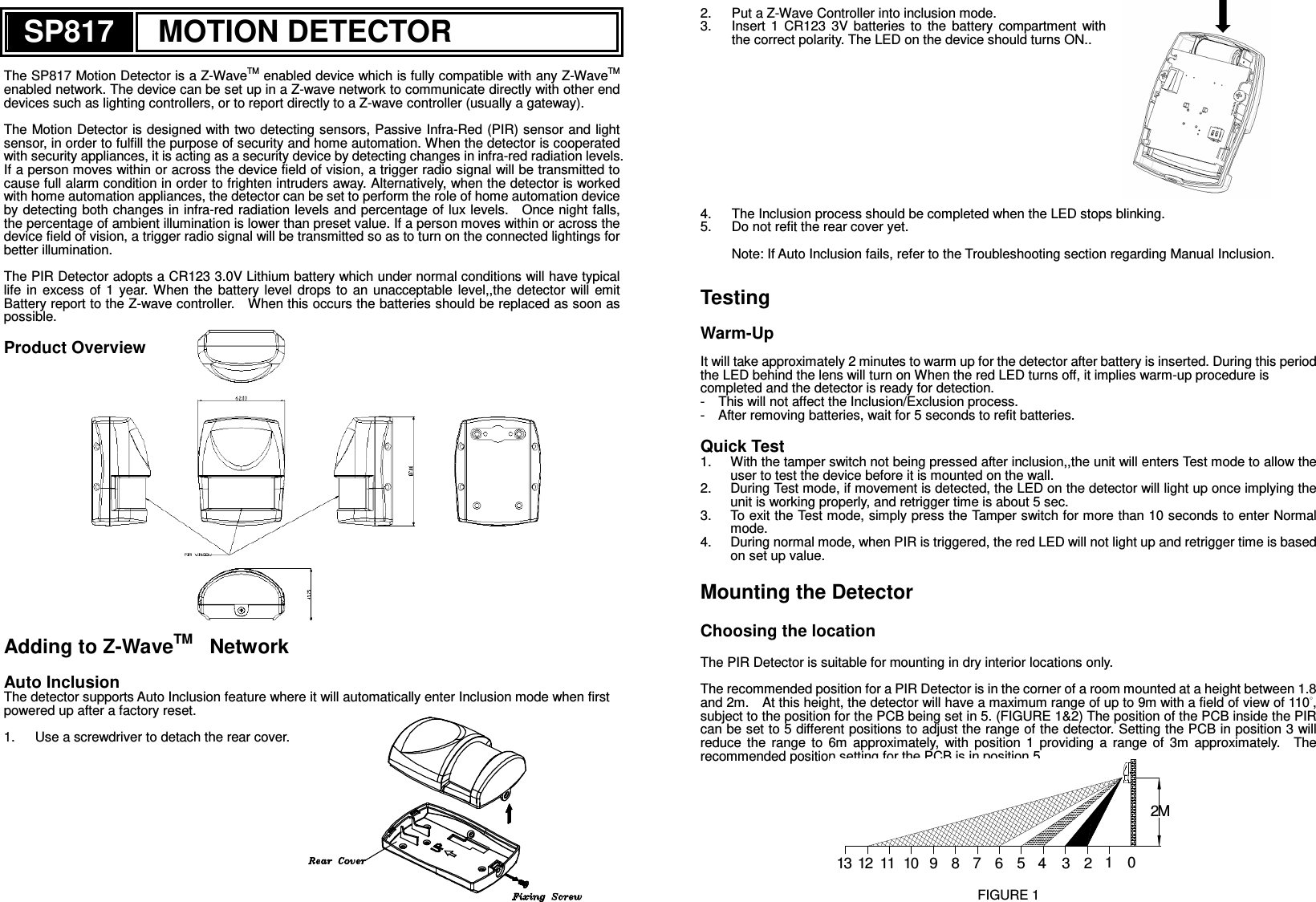
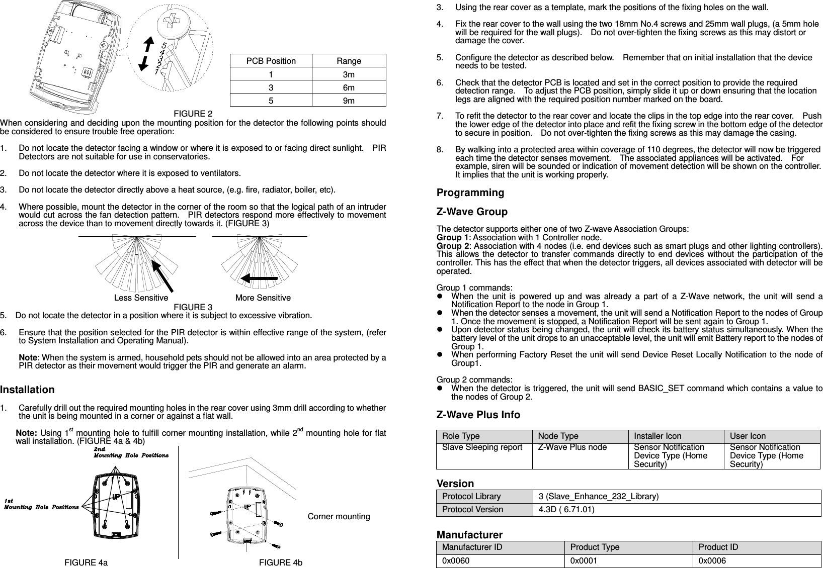
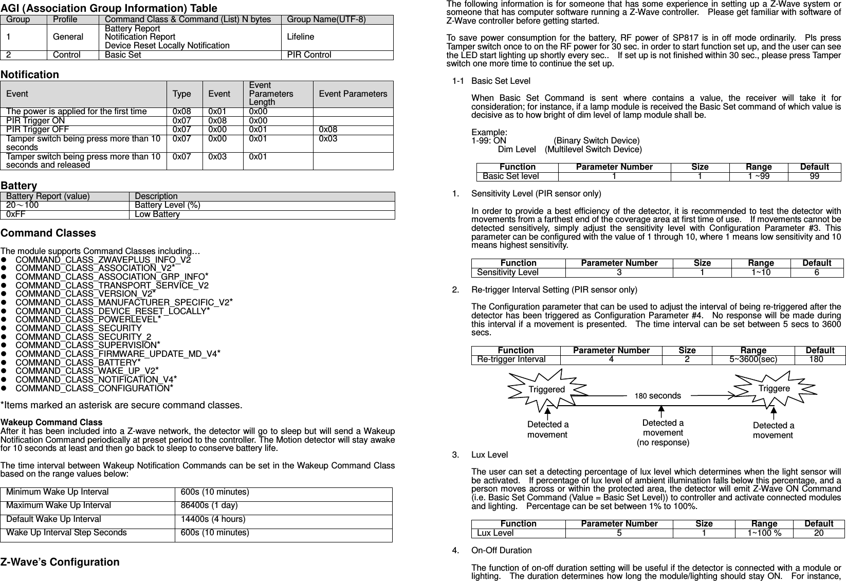
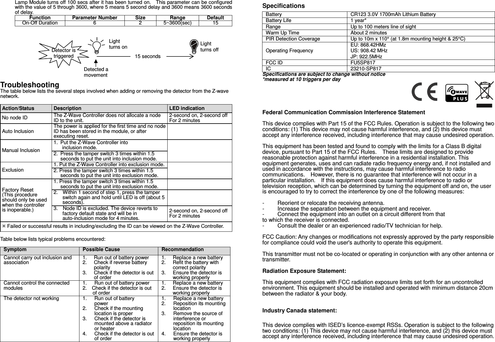
SP817 User Manual
User Manual
Navigation menu
Upload a User Manual
Namespaces
Wiki Guide
HTML
PDF
Info
Views
User Manual
Discussion / Help
Navigation