Everspring Industry Co SR101 Chime Remote Button User Manual
Everspring Industry Co Ltd Chime Remote Button
User Manual
1
Simple Alarm System
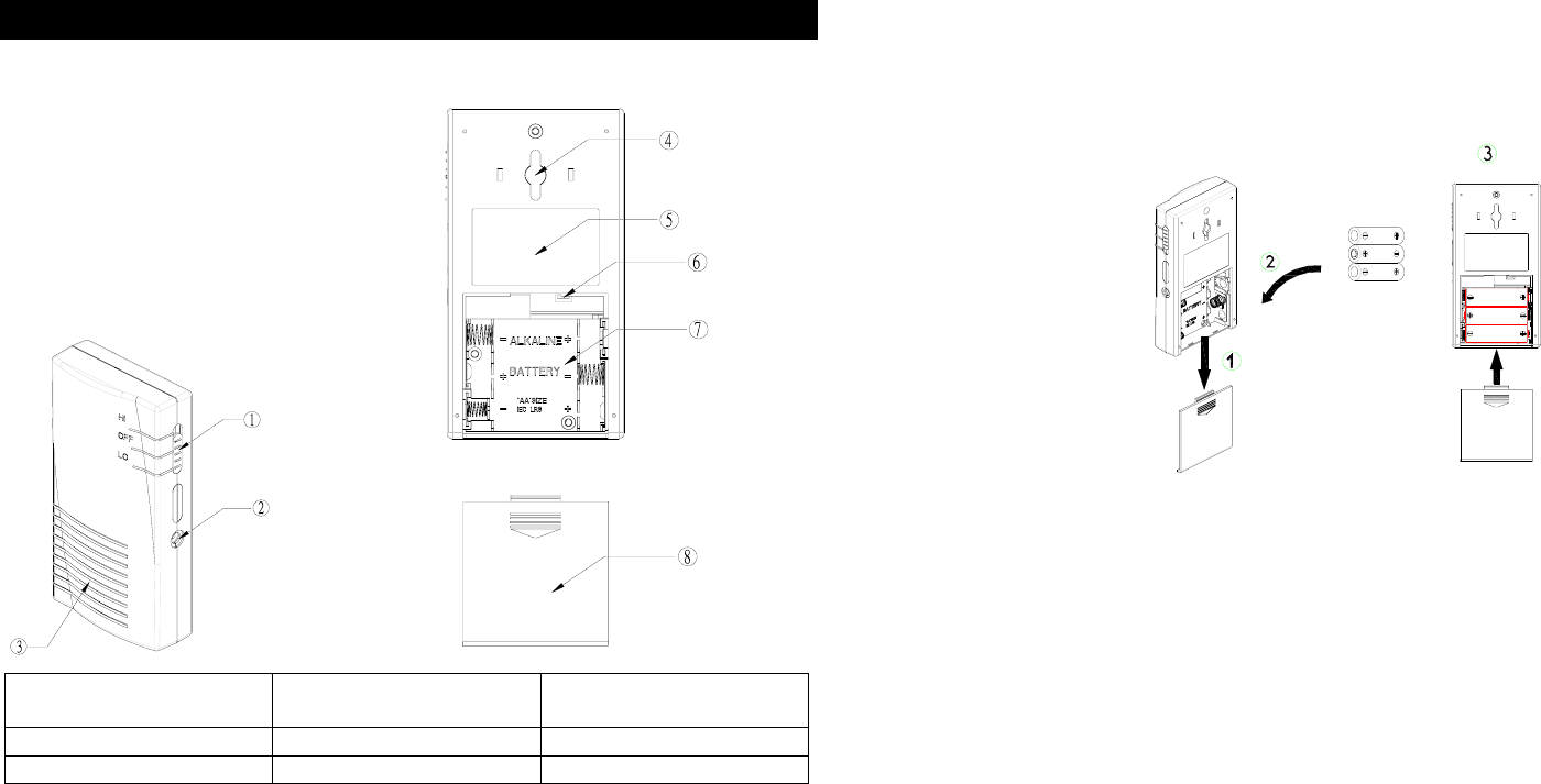
Portable RF 2-tone Sounder
1 3-position slide switch
Power/volume/mode selection
4 Hanging Slot 7 Battery Compartment
2 Jack for AC adapter 5 Sticker 8 Battery Cover
3 Buzzer 6 Code Learning Button
The Portable RF 2-tone Sounder, a 2-in-1 wireless receiver, is designed to work
with the Magnetic Contact Detector (SM101), Wireless PIR Detector (SP101) and
Chime Remote Button (SR101), serving as an audible chime or alarm.
Before selecting a position for the Sounder the following points should be noted:
1. Do not fix the Sounder to metalwork or locate the unit within 1m of metalwork
(i.e. radiator, water pipes etc) as this could affect the radio range of the unit.
2. Do not locate the Sounder directly above a heat source, (e.g. fire, radiator,
boiler, etc)
3. Do not locate the Sounder where it is exposed to ventilators.
Loading the Battery
1. Open the battery cover. (FIGURE 1)
2. Insert 3 AA-size 1.5V batteries to the battery compartment, ensuring that correct
polarity is put.
3. Refit the battery cover.
FIGURE 1
Setting
1. The Sounder is able to memorize 10 set of individual codes.
2. Code learning
Note: For the best results, keep approx. 1 meter away from the transmitters
when proceeding with the code learning. The minimum distance between the
receiver and transmitter for code learning is 15 cm.
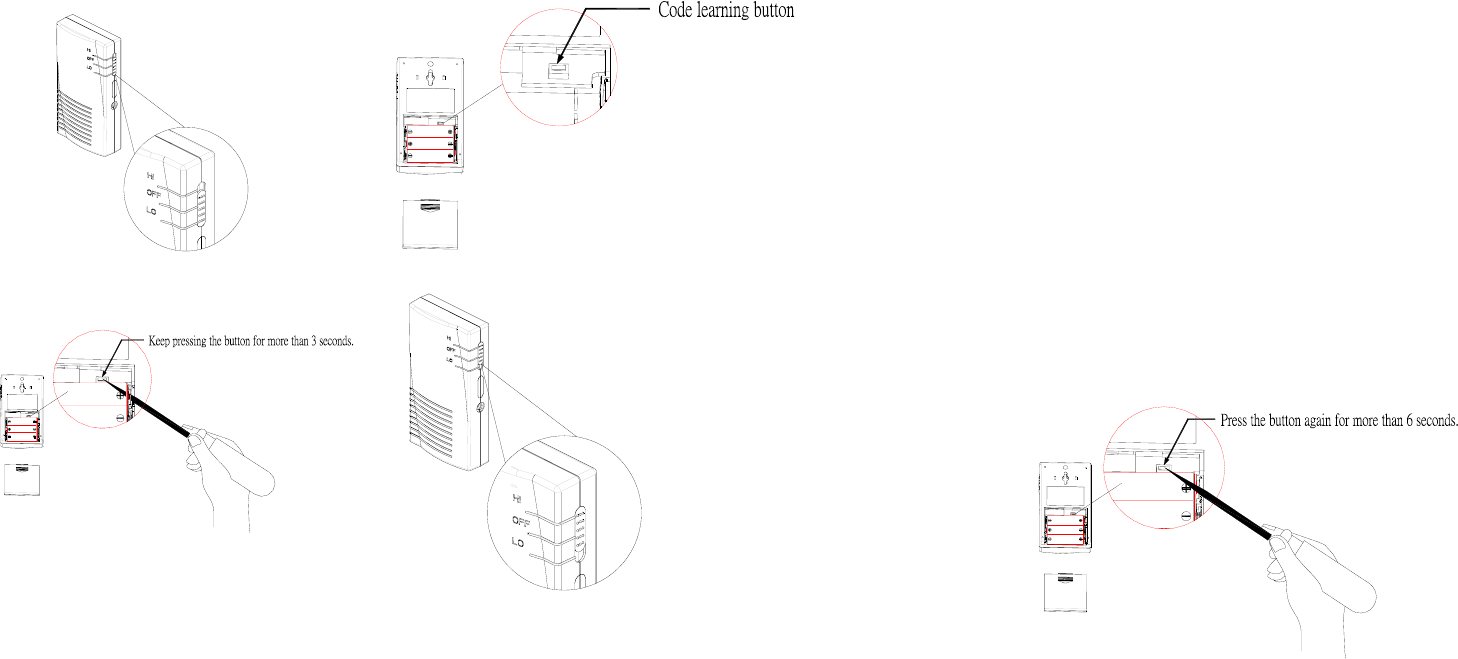
a. Setting the chime code
Step 1: Set the 3-position slide switch to “LO”. (FIGURE 2a)
Step 2: Open the battery cover.
Step 3: Using a ball-point pen, press and hold the code learning button for
more than 3 seconds. (FIGURE 2b & 2c)
Step 4: Keep holding the button. The Sounder will bleep per second.
After a long bleep being heard, it will enter code learning mode.
Step 5: Upon entering the code learning mode, release the button. The
Sounder is about to receive the code learning command within
30 seconds. During this 30 seconds period, the Sounder will react
with a long bleep as a confirmation if the code learning is successful.
Wait for at least 3 seconds to start operating.
Step 6: Upon entering the code learning mode, release the button. The
Sounder is about to receive the code learning command within 30
seconds. During this 30 seconds period, the Sounder will emit four
2
bleeps consecutively as a warning if the code learning is failure.
Follow the below step for resolution.
Step 7: Starting from Step 1 to retry and refer to the troubleshooting’s
instruction for invalid code learning.
FIGURE 2a FIGURE 2b
FIGURE 2c FIGURE 2d
b. Setting the alarm code:
Step 1: Set the 3-position slide switch to “HI”. (FIGURE 2d)
Step 2: Open the battery cover.
Step 3: Using a ball-point pen, press and hold the code learning button for
more than 3 seconds. (FIGURE 2b & 2c)
Step 4: Keep holding the button. The Sounder will bleep per second.
After a long bleep being heard, it will enter code learning mode.
Step 5: Upon entering the code learning mode, release the button. The
Sounder is about to receive the code learning command within 30
seconds. During this 30 seconds period, the Sounder will react with a
long bleep as a confirmation if the code learning is successful.
Wait for at least 3 seconds to start operating.
Step 6: Upon entering the code learning mode, release the button. The
Sounder is about to receive the code learning command within 30
seconds. During this 30 seconds period, the Sounder will emit four
bleeps consecutively as a warning if the code learning is failure. Follow
the below step for resolution.
Step 7: Starting from Step 1 to re-try and refer to the advice shown on the
Troubleshooting’s invalid code learning.
3. Cleaning the code
All the codes preset will be cleaned by taking the following steps.
Step 1: Open the battery cover.
Step 2: Using a ball-point pen, press the code learning button for more than 3
seconds. (FIGURE 2b & 2c)
Step 3: Keep holding the button. The Sounder will bleep per second. After a
long bleep being heard, it will enter the code learning mode.
Step 4: Upon entering the code learning mode, release the button. Before
receiving the code learning command, press and hold the button
immediately again for more than 6 seconds. (FIGURE 3) The Sounder
will bleep per second. After 6 bleeps being heard, all the preset
memory will be eliminated.
FIGURE 3
Installation
Upon completion of code learning procedure, fix the Sounder to the wall using the
screws and plastic wall plugs supplied. Or it can be free standing, serving as a
portable annunciator or intrusion alarm. (FIGURE 4)
3
129630
2.0
6
9
3
0
3
6
9
FIGURE 4
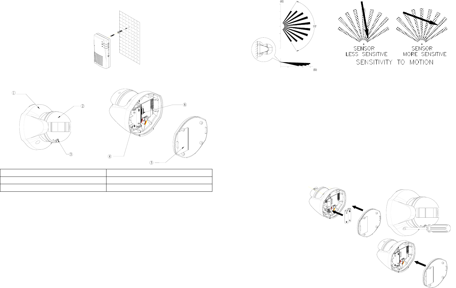
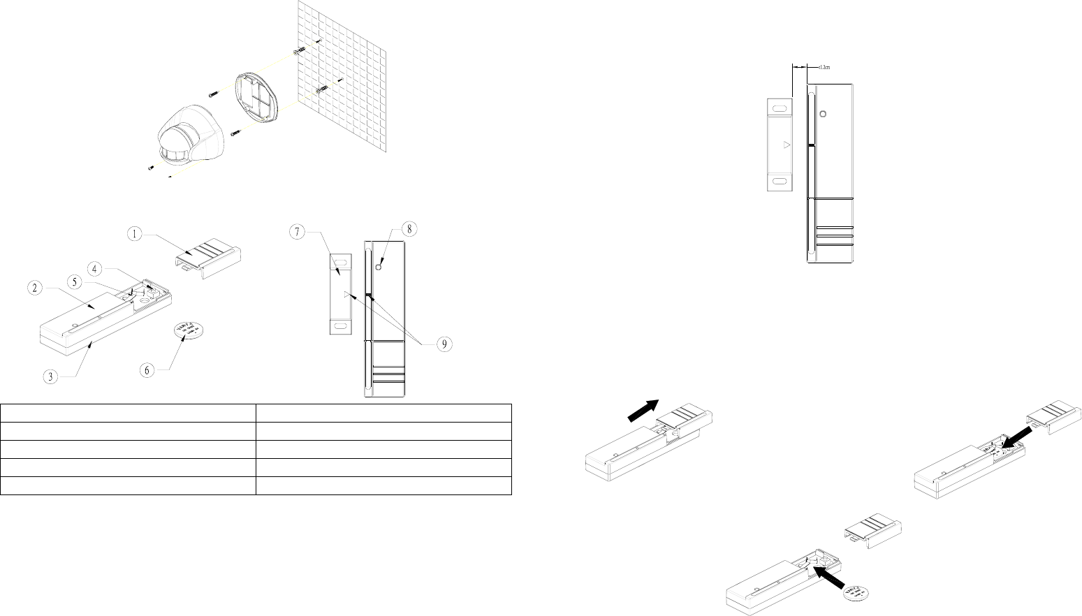
Wireless PIR Detector
1 Top Cover 4 Battery
2 PIR Motion Sensor 5 Back Cover
3 Time-off Knob 6 Tamper Switch
The PIR Detector is designed to detect movement in a protected area by detecting
changes in infra-red radiation levels caused, for example, when a person moves
within or across the devices field of vision. If movement is detected a radio signal
will be emitted to the Sounder.
The recommended position for a PIR Detector is in the corner of a room mounted
2m from the floor. At this height, the detector will detect movement up to 8-12m
depending on adjustment. (FIGURE 5a) Also, in this position, the 110 degrees
fan-shaped detection pattern can normally offer greater protection than mounting on
a flat wall. Before selecting a position for a PIR Detector the following points should
be noted:
FIGURE 5a FIGURE 5b
1. Do not position the detector facing a window or direct sunlight. PIR Detectors
are not suitable for use in conservatories or draughty areas.
2. Do not position the detector directly above or facing any source of heat, eg: fires,
radiators, boiler etc.
3. Where possible, mount the detector so that the logical path of an intruder would
cut across the fan pattern rather than directly towards the detector.(FIGURE 5b)
4. The PIR Detector can be used with Sounder, providing they are all coded with
the same code.
Loading the battery
1. Using a Phillips screwdrivers to detach the back cover. (FIGURE 6a)
2. Insert 2 AAA-size 1.5V batteries to the battery compartment, ensuring that
correct polarity is put. (FIGURE 6b)
3. Refit the back cover. (FIGURE 6c)
FIGURE 6a FIGURE 6b FIGURE 6c
Setting
1. There is an individual code that is fixed ex-factory and cannot be adjusted.
2. Code learning
Step 1: Set the Sounder to code learning mode. (For chime code, refer to page
4
1 Step1-4, for alarm code, see page 2 Step 1-4).
Step 2: Insert the batteries to the PIR Detector.
Step 3: Pressing the tamper switch will emit radio signal to the Sounder
instantly. When emitting the individual code to the Sounder, the
PIR Detector won’t detect until the back cover is fitted after 6 seconds.
Step 4: If the Sounder reacts with a long bleep, the code learning is successful.
Wait for 6 seconds for the Detector to enter normal detection mode.
Step 5: If the Sounder bleeps four times consecutively, the code learning is
failure. Follow the below steps for resolution.
Step 6: Starting from Step 1 to re-try and refer to the advice shown on the
Troubleshooting’s invalid code learning.
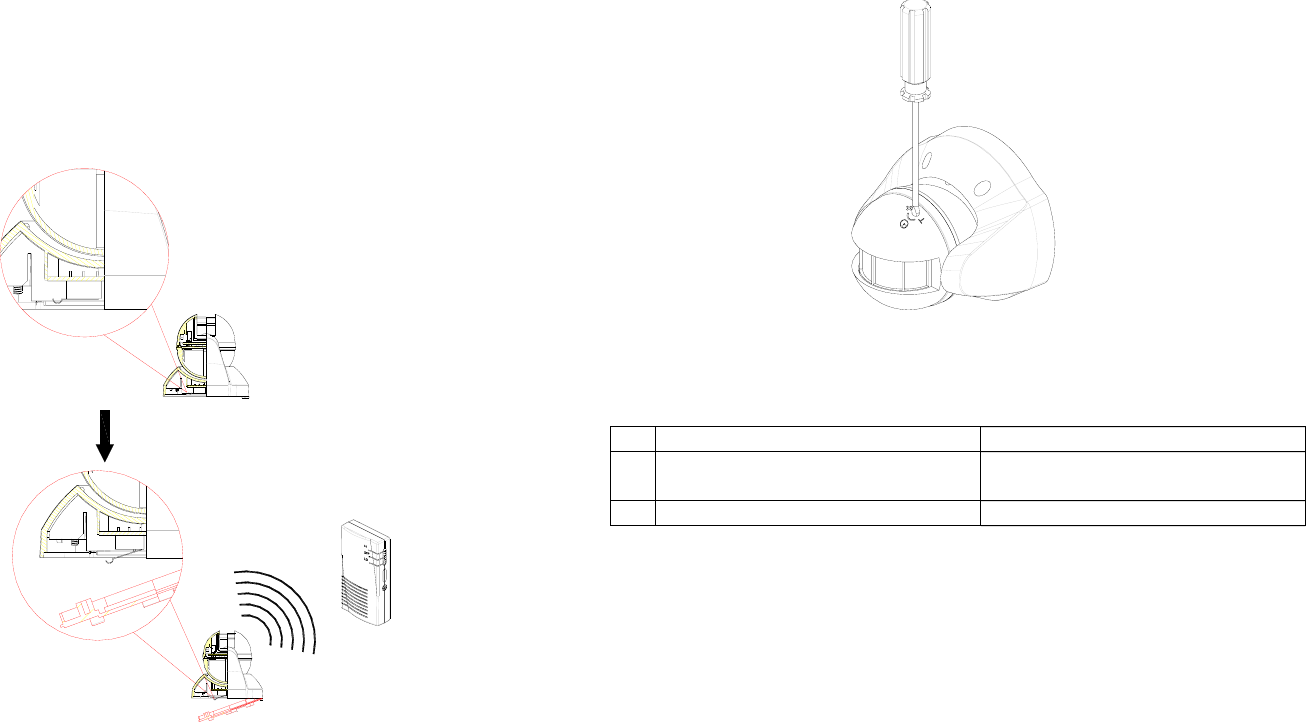
Operation
1. When removing the back cover, the tamper switch will be triggered. Trigger
command of radio signal will emit every 3 seconds. With such recurrence for 3
times, It will enable the Sounder to alarm. (FIGURE 7)
FIGURE 7
2. By refitting the back cover after 6 seconds, the PIR detector will enter normal
detection mode.
3. The PIR Detector is designed to detect movement within a protected area.
The detector element detects differences in the infra red radiation when a
person moves within the protected area. If movement is detected, a radio
signal is transmitted to the Sounder to activate the chime or alarm.
4. Time-off knob is designed to control the length of time that the appliances
should be turned off. It is set from 5 seconds to 12 minutes. “T” means 5
seconds, while “+” is 12 minutes. (FIGURE 8)
FIGURE 8
5. A LED is mounted inside of the PIR Detector. The indication of LED represents
the following status:
Status LED indication
1 PIR Detector is emitting radio
signal Illuminating steadily
2 Low battery Keep flashing slowly
Installation
As soon as the code learning procedure is completed, hold the back cover in
position and mark the two mounting holes. Drill the holes, insert the plastic wall
plugs and screw the back cover to the wall using the screws supplied. Offer the
Detector up to the back cover using screws as originally supplied. (FIGURE 9)
5
FIGURE 9
Magnetic Contact Detector
1 Battery Cover 6 Battery
2 Top Cover 7 Magnet
3 Back Cover 8 LED
4 Tamper Switch 9 Arrow
5 Battery clip
Magnetic Contact Detectors can be fitted to protect doors or windows. If the
protected doors or windows are opened, a radio signal will be transmitted to the
Sounder for audible warning.
Before fixing the detector to a metal door/window check the radio range. It may be
necessary to space the Magnet/Detector off the metal surface using a plastic or
wooden spacer to achieve the necessary radio range.
Fix the Detector and Magnet to the opening using either the double sided tape or
screws provided. Mount the Magnet to the door and the Detector to the door frame
(or vice versa, if necessary). Ensure that the arrows on the Magnet and Detector
are pointing towards each other and that the gap between the Detector and the
Magnet is less than 12mm. (FIGURE 10)
FIGURE 10
Loading the battery
1. Remove the battery cover by sliding off. (FIGURE 11a)
2. Fit the 3V Lithium battery supplied, with the positive (+) facing upwardly.
(FIGURE 11b)
3. Refit the battery cover. (FIGURE 11c)
FIGURE 11a FIGURE 11b FIGURE 11c
Setting
1. There is an individual code that is fixed ex-factory and cannot be adjusted.
2. Code learning
Step 1: Fit the battery.
Step 2: Set the Sounder to the code learning mode.
Step 3: Press the tamper switch on the Detector.
Step 4: If the Sounder has a long bleep, the code learning is successful and can
start operating. If not, it implies that the code learning is failure. Please
6
go ahead with the below step.
Step 5: Starting from Step 2 to re-try and refer to the advice shown on the
Troubleshooting’s invalid code learning.
Operation
1. When pressing the tamper switch, the Detector will transmit a radio signal to the
Sounder as code learning command.
2. Upon opening the battery cover, the tamper switch will be triggered. A radio
signal will be also emitted to the Sounder for alarming.
3. Separating the magnet from the Detector, a radio signal will be emitted to the
Sounder for chime alerting or alarming.
4. The indication of LED represents the following status:
Status LED indication
1 Magnetic Contact Detector is
emitting radio signal Illuminating steadily
2 Low battery Keep flashing slowly
Installation
1. Choose a position to drill a hole, insert the plastic wall plug and fix a screw on
the wall. Hang up the Detector on the screw. (FIGURE 12a)
2. Knock out the groove adjacent to the battery compartment and insert the screw
to fix the Detector on the wall. (FIGURE 12b)
Note: Ensure that the screw is driven flush with the inside of the casing hole.
FIGURE 12a FIGURE 12b
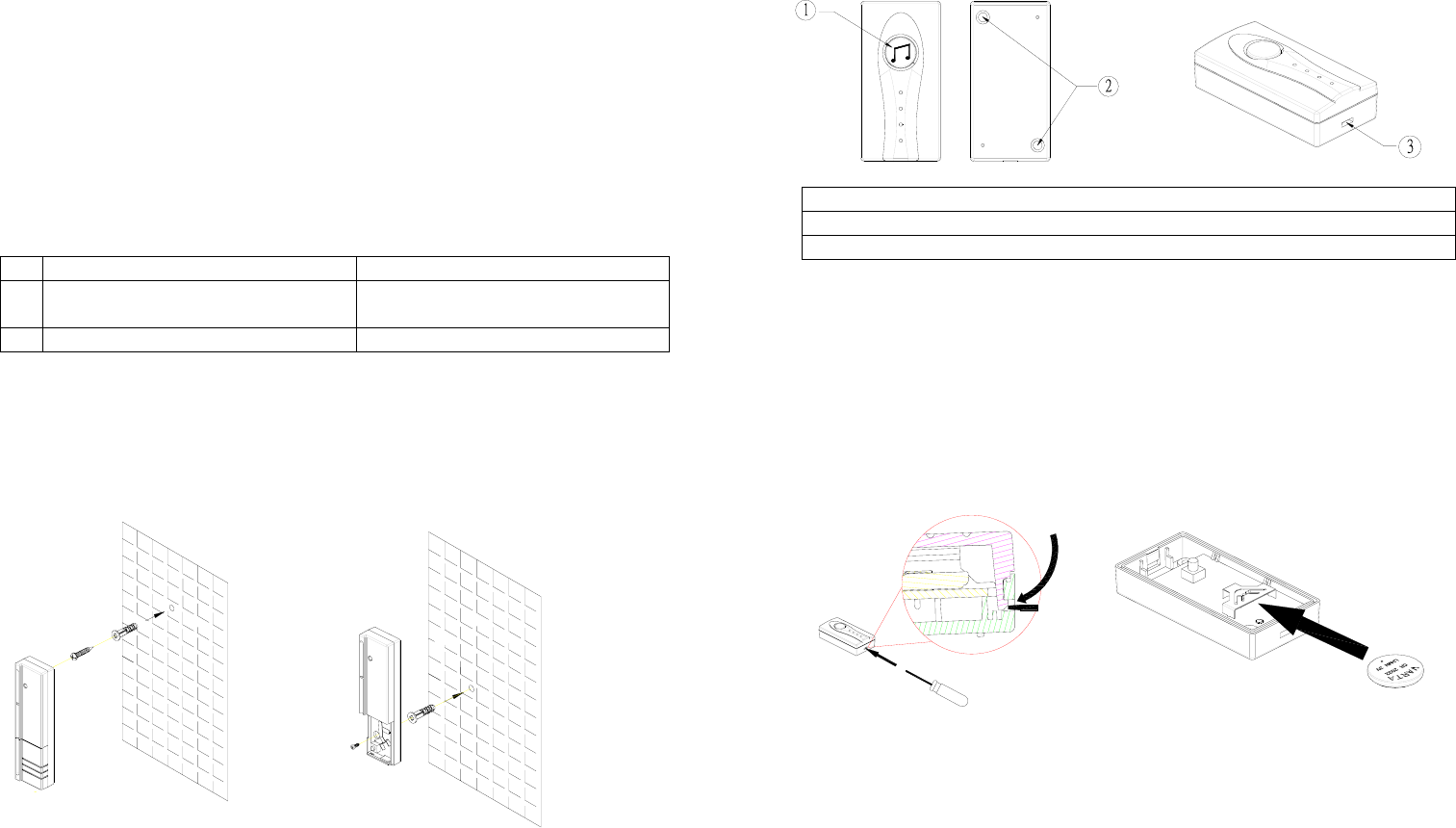
Chime Remote Button
1 Button
2 Fixing hole
3 Top Cover Groove
The Chime Remote Button is a wireless transmitter. Pressing its button will
initiate the Sounder for audible warning.
Loading the battery
1. Using a Phillips screwdriver from the top cover groove to detach the top
cover. (FIGURE 13a)
2. Fit a 3V Lithium battery to the battery compartment with positive (+)
polarity facing upwardly. (FIGURE 13b)
3. Refit the top cover. (FIGURE 13c)
FIGURE 13a FIGURE 13b
7
FIGURE 13c
Setting
1. There is an individual code that is fixed ex-factory and cannot be adjusted.
2. Code learning
Step 1: Insert the battery.
Step 2: Set the Sounder to the code learning mode.
Step 3: Press and hold the button on the Remote Button for more than 6
seconds.
Step 4: If the Sounder reacts with a long bleep, the code learning is
successful and can start operating.
Step 5: If the Sounder reacts with four bleeps consecutively, the code
learning is failure. Follow the below step for resolution.
Step 6: Starting from Step 2 to retry and refer to the troubleshooting’s
instruction for invalid code learning.
Operation
1. The Remote Button is a pocket-sized, easy-to-carry transmitter.
2. Press and release the button on the Remote Button. The Sounder will
acknowledge the signal by emitting either a chime alert or alarm sound.
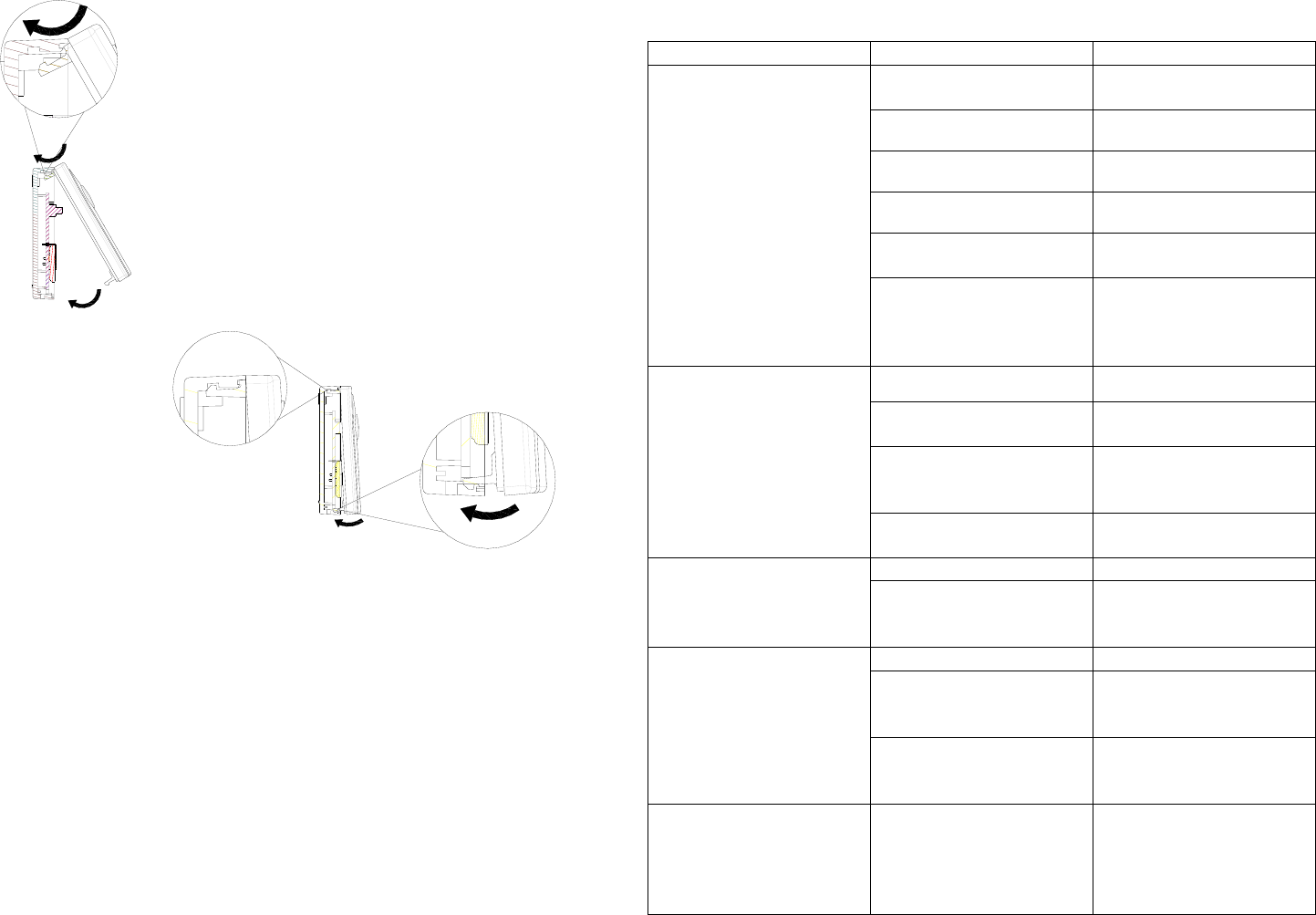
Troubleshooting
Symptom Possible Cause Recommendation
Power is off Set 3-position slide
switch to Hi or Lo
Not loading the battery Fit the battery
Reverse battery polarity Refit battery
Run out of battery Replace a new battery
Incorrect code learning
procedure Follow the steps as
described on the manual
Sounder invalid code
learning
Beyond code learning
capacity Proceed “cleaning the
code” and resume “code
learning” procedure
again
Run out of battery Replace a new battery
Code has not been
learned Follow the code learning
procedure
Any obstacle or metallic
object is blocked Remove obstacle or
change transmitters’
mounting location
Sounder not responding
to transmitters
Out of radio range Change transmitters’
mounting location
Run out of battery Replace a new battery Sounder’s volume
become weak Check if 3-position slide
switch is set at Hi
position
Set it at Hi position
Run out of battery Replace a new battery
Check if mounting
location of detector is
proper
Adjust mounting location
PIR Detector not working
Radio interference Remove interference
source or change
mounting location
Magnet not working Check if the arrows on
the magnet and detector
are pointing toward each
other and that the gap is
less than 12mm
Adjust their position and
gap

8
Run out of battery Replace a new battery
Code has not been
learned Proceed “code learning”
with the Sounder
Specifications
Portable RF 2-tone
Sounder
Wireless PIR
Detector
Magnetic Contact
Detector
Chime Remote
Button
Battery 3 X 1.5V AA 2 x 1.5V AAA 1 x 3V
CR2032
1 x 3V CR2032
Communication
Range
70 meters min. (in an open space)
Specifications subject to change without notice INUA101EVSP0E1A
Federal Communication Commission Interference Statement
This equipment has been tested and found to comply with the limits for a Class B
digital device, pursuant to Part 15 of the FCC Rules. These limits are designed to
provide reasonable protection against harmful interference in a residential
installation. This equipment generates, uses and can radiate radio frequency
energy and, if not installed and used in accordance with the instructions, may cause
harmful interference to radio communications. However, there is no guarantee
that interference will not occur in a particular installation. If this equipment does
cause harmful interference to radio or television reception, which can be determined
by turning the equipment off and on, the user is encouraged to try to correct the
interference by one of the following measures:
- Reorient or relocate the receiving antenna.
- Increase the separation between the equipment and receiver.
- Connect the equipment into an outlet on a circuit different from that to which the
receiver is connected.
- Consult the dealer or an experienced radio/TV technician for help.
This device complies with Part 15 of the FCC Rules. Operation is subject to the
following two conditions: (1) This device may not cause harmful interference, and (2)
this device must accept any interference received, including interference that may
cause undesired operation.
FCC Caution: Any changes or modifications not expressly approved by the party
responsible for compliance could void the user's authority to operate this
equipment.
IMPORTANT NOTE:
FCC Radiation Exposure Statement:
This equipment complies with FCC radiation exposure limits set forth for an
uncontrolled environment. End users must follow the specific operating instructions
for satisfying RF exposure compliance.
This transmitter must not be co-located or operating in conjunction with any other
antenna or transmitter.